rexresearch
Michael ELLSWORTH
Atmospheric Water Generator
A2WH ( Air to Water Harvest )
(AWG)
Atmospheric Water Generator using solar energy
A2WH ( Air to Water
Harvest ) technology extracts the humidity in air and
converts it into liquid water. A2WH is a new generation
of solar powered atmospheric water generator device (AWG)
which are also known as water maker devices (WM) and Water Air
Extraction Devices (WAED). A2WH uses a
revolutionary patent pending solar heat design which does not
require refrigeration. This allows A2WH to operate
cost effectively directly from renewable energy and makes A2WH
ideal for off grid deployment, remote cabins, islands and
other locations where electricity is abnormally expensive.
...
A2WH has designed a patent pending solar thermal powered
system which is fundementally different than common
refrigeration based units. The A2WH design allows allow us to
absorb moisture from relatively dry air with a much lower
energy cost. We use solar heat which keeps the energy
costs low. A major difference is that we can
condense at ambient which eliminates the need for
refrigeration which is the big electricity consumer in most
other WAED units.
This allows A2WH to be
deployed in large scale and to provide much lower operational
costs. These combine to make A2WH scalable from a few liters per
day through millions of gallons.
A2WH requires full sun
exposure. This means it must be installed outside in areas
without significant shade.
With a single acre of land the A2WH A2WH
units can produce in the range 1,000 to 2,500 gallons per day of
water without having any impact on the local water company or
drawing any power from the local utility company...
...The A2WH A2WH units
do not impact the local ground water and they are using a
resource that is completely renewable so there is no risk of
running out in the future...
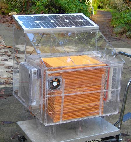
A2WH Product Overview
The A2WH system produces pure potable water
from air using only solar energy. It operates with a much
lower operating cost than other AWG systems because it does not
require large amounts of electricity.
The A2WH system absorbs moisture at night
when humidity is relatively high and converts what it absorbed
the prior night into liquid water the following day using solar
thermal heat. Well over 90% of the energy used in the system is
solar heat.
In this system all condensing occurs at
near ambient and it does not require any refrigeration. High
quality filters are used to filter the air before the absorption
at night which keeps the interior of the system very
clean.
A HEPPA grade filter is used for the gas
entering the condenser chamber which keeps the water quality
near surgical grade. The system includes an automatic mode where
it sterilizes the condensing area on days when there is
sufficient solar energy to reach pasteurization temperatures.
A small amount of energy is delivered by
Photo Voltaic panels which operate a microcomputer control
system, sensors, blowers, pumps, etc...
How does
A2WH work?
The A2WH system uses a
desiccant to absorb moisture from the air. The
higher the humidity the more water our desiccant can absorb per
pass which increases production.
We use solar heat to
drive both the airflow for the absorption process and to provide
heat during the regeneration process which extracts the moisture
from the desiccant and allows us to capture the water in liquid
form.
A sophisticated micro
controller based sensor system determines when to switch between
absorption and regeneration modes. We use different
types and amounts of desiccants depending on the local
conditions to optimize the performance of the
system. A small Photo Voltaic
solar panel provides power for the micro controller, sensors,
various valves, etc.
We have an optional
enhancement that uses wind energy (wind over 4.5 MPH) to drive
circulation at night when the relative humidity is higher.
To make this work best we increase the weight of the
desiccant used in the system. In some areas with
good nightly wind this allows the unit to work in areas with
daytime humidity as low as 10% We have optional
enhancements which allow electric fans and heaters to augment or
replace the solar heat.
The input air is
filtered before it enters the absorption chamber where the
desiccant absorbs water out of it. The air is re-filtered
when heated for regeneration. A final stage of filtering
is used as the air enters the condensation phase where the H2O
is turned into liquid water. As a result the output water
is very pure. We still recommend treatment
using a NSF 54 grade filter prior to consumption because we do
not have any control over the cleanliness of the storage
tank....
Our difference from common market
units.
Most Air to water
systems use refrigeration to chill air to the dew point that
means that as the dew point drops the more the unit must do more
work to sufficiently chill the air. This
causes them to use large amounts of electricity. It is
fairly common for electric units to consume of 2.2Kwh per gallon
produced which gives them a high variable operating costs which
can exceed 40 cents per gallon.
We designed A2WH units
to operate entirely from solar energy. This is mostly
solar heat with a small amount of solar electricity used to
operate valves, sensors and the electronic control
system. This allows our system to operate much more
efficiently which is especially important in areas where
electricity is expensive such as islands where electricity is
generated using imported fuels.
Most AWG systems are
built around a refrigeration system which is very similar to
that used in small electric air conditioners. The best
units consume 600 to over 3,000 watt hours per gallon of water
they produce. The industry average trends
show consumption over 2,2000 watt hours per gallon which
rise rapidly as humidity drops.
A2WH functions with no
external electricity. This saves 3,000 watts per gallon.
Our novel design and control system allows it to efficiently
extract water in a wide range of conditions including conditions
where electric AWG units become inefficient or do not work at
all.
Our units can reduce
carbon emissions by over 5 pounds of carbon per gallon produced
as compared to grid powered electric systems. (2.2 pounds
carbon per KWh saved * 3000 watts per gallon = 6.4 pounds
of carbon per gallon of water). Even a small 6
gallon per day system this adds up to nearly 11,000 pounds
reduced carbon emissions per year.
Our system uses solar
thermal heat to harvest water from air even when the air has low
humidity. Unlike radiant condensation systems this
system actually produces during the dry months even when there
is no dew and it's production can go up in windy locations which
can prevent radiant chilling systems from working at
all. Our technology can work in conditions where the
dew point is far below the chilling level delivered by radiant
chilling panels.
Our most important
difference is the compatibility of the core design for scaling
efficiently into millions of gallons per day at a reasonable
cost. It's other major benefit is compatibility with
remote areas where grid power is either unavailable or
expensive. In some areas our units can be installed
in mountains outside of towns and provide both water pressure
and electricity for the town. Rather than exaggerate
summer power shortages our system can actually help reduce these
shortages.
Absorption/regeneration
non-conventional system for water extraction from
atmospheric air
Ahmed Sultan, et al.
Abstract -- The present work
suggests a non-conventional method of water production from
atmospheric air, on a 24-h basis using a compact system. The
operation of the system is described and its efficiency is
defined. The system performs under forced convection absorption
and regeneration through a packed tower. The packed tower
consists of two identical columns, each of them is packed with
an identical bed. Each bed consists of vertical multi-layers of
cloth material impregnated with calcium chloride solution of
different concentrations. A numerical model, based on the
experimental results, has been developed to predict the
performance of the system under various operating conditions.
The system efficiency is found to have peak values at certain
cycle times, desiccant final concentration, regeneration
temperature and absorption air stream velocity. It is also found
that the maximum efficiency increases with initial concentration
and decreases with the increase of the regeneration air stream
velocity and absorption temperature.
US6490874
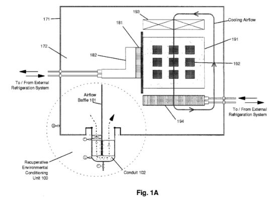
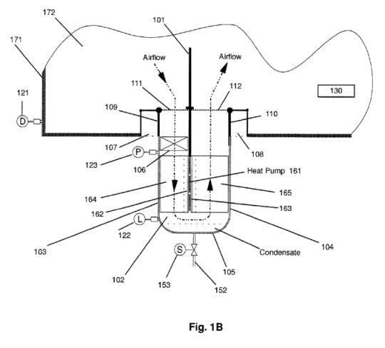
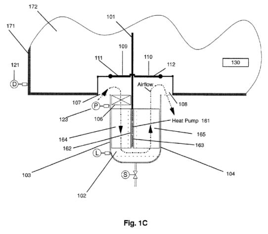
Recuperative Environmental
Conditioning Unit
Abstract -- A method and
apparatus for removing moisture from within an electronics
enclosure is provided. In particular, dehumidification is
accomplished by removing air from the enclosure, cooling the
air thereby causing condensation of water vapor from the air,
then heating the dehumidified air and returning the heated and
dehumidified air to the enclosure. A single heat pump provides
cooling and heating functions, effectively recouping heat
extracted from the air to be cooled, and transferring the
extracted heat to the air prior to its return to the
enclosure. In this manner, electronics within the enclosure
may be operated at temperatures below the dew point of ambient
air surrounding the enclosure, without requiring a thermally
insulated enclosure. Devices are provided to collect and purge
condensate from the system, either in a continuous or periodic
manner.; Embodiments employing conventional vapor compression
cycle heat pumps and thermoelectric heat pumps are described.
A defrost cycle is provided to eliminate frost that may
accumulate on the heat exchanger associated with the heat pump
normally cold element. Defrost is accomplished by reversing
heat pump polarity, heating the normally cold element. Control
mechanisms and logic are provided to automate system
operation. In preferred embodiments, dehumidification and
defrost modes are activated by a controller monitoring the dew
point within the enclosure, and the air pressure at the
normally cold element. Dehumidification is performed
intermittently, when the enclosure dew point exceeds a set
point. Substantially sealing the enclosure against ingress of
ambient air reduces the system's operational duty cycle.
FIG. 1A shows a side
view of an electronics enclosure with an external
recuperative environmental conditioning unit (RECU)
according to one embodiment of the present invention;
FIG. 1B shows a side
detail view of the RECU of FIG. 1A in normal operation;
FIG. 1C shows a side
detail view of the RECU of FIG. 1A, in defrost mode;
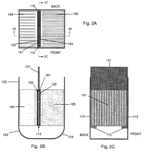
FIG. 2A shows a plan
view of the thermoelectric heat pump and heat exchangers
according to one embodiment of the present invention;
FIG. 2B shows a cutaway
view of the thermoelectric device depicted in FIG. 2A, taken
along lines B--B;
FIG. 2C shows a cutaway
view of the thermoelectric device depicted in FIG. 2A, taken
along lines C--C;
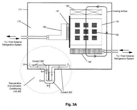
FIG. 3A shows a side
view of an electronics enclosure with an external RECU,
according to an alternative embodiment of the present
invention;
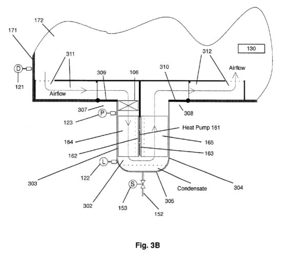
FIG. 3B shows a side
detail view of the RECU of FIG. 3A in normal operation;
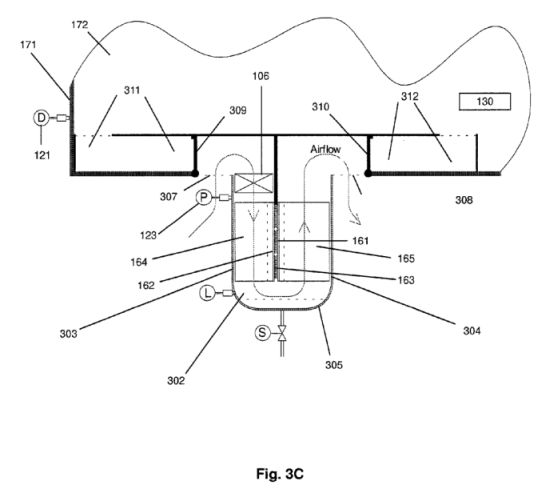
FIG. 3C shows a side
detail view of the RECU of FIG. 3A, in defrost mode;
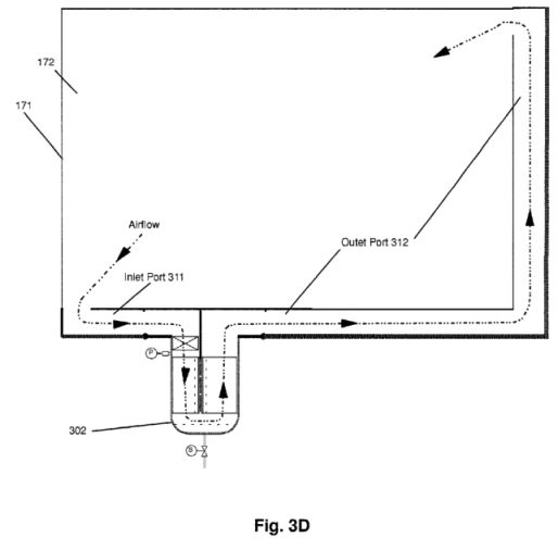
FIG. 3D shows a side
detail view of an RECU employing an extended outlet port;
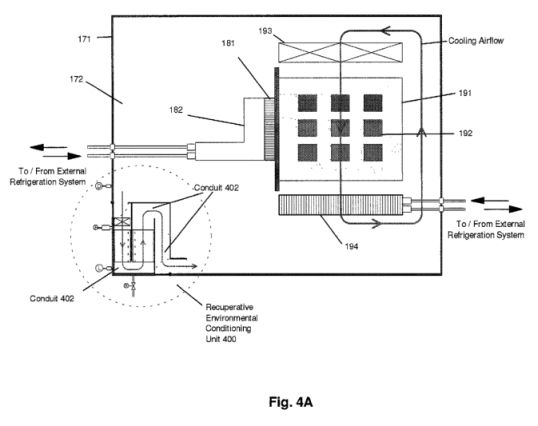
FIG. 4A shows a side
view of an electronics enclosure with an internal RECU
according to one embodiment of the present invention;
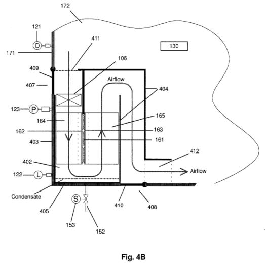
FIG. 4B shows a side
detail view of the RECU of FIG. 4A in normal operation;
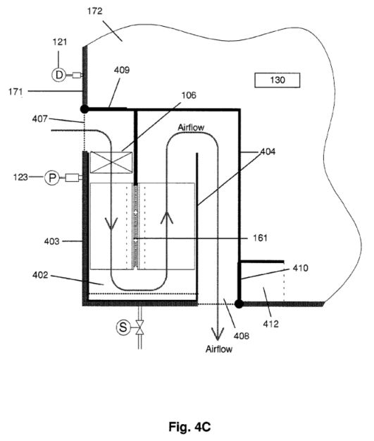
FIG. 4C shows a side
detail view of the RECU of FIG. 4A, in defrost mode;
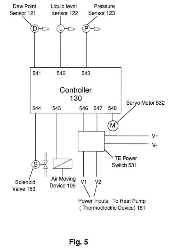
FIG. 5 shows a schematic
view of the control devices of one embodiment of the present
invention;
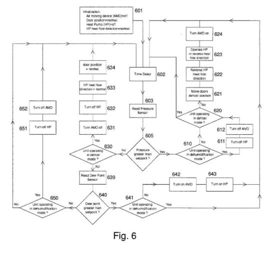
FIG. 6 shows a flow
diagram depicting the RECU control flow, for both the
dehumidification and the defrost operations according to one
embodiment of the present invention;
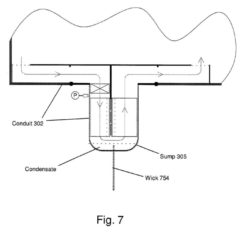
FIG. 7 shows the RECU of
FIG. 3A, using a wick to remove condensate.
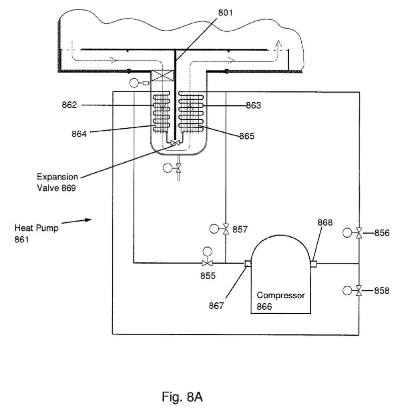
FIG. 8A shows an RECU
using a vapor compression cycle heat pump according to one
embodiment of the present invention;
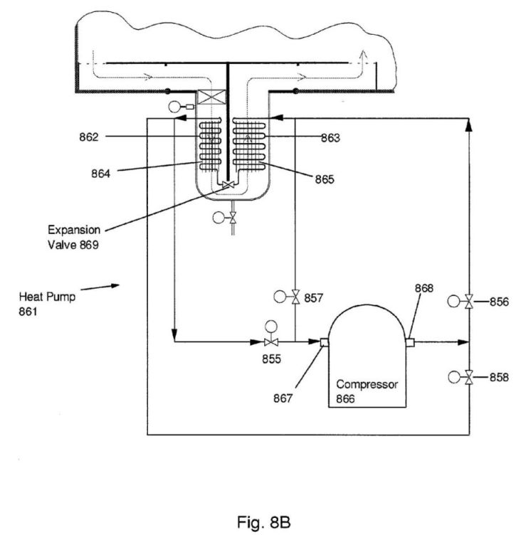
FIG. 8B shows the
operation of the embodiment of FIG. 8A during normal
operation;
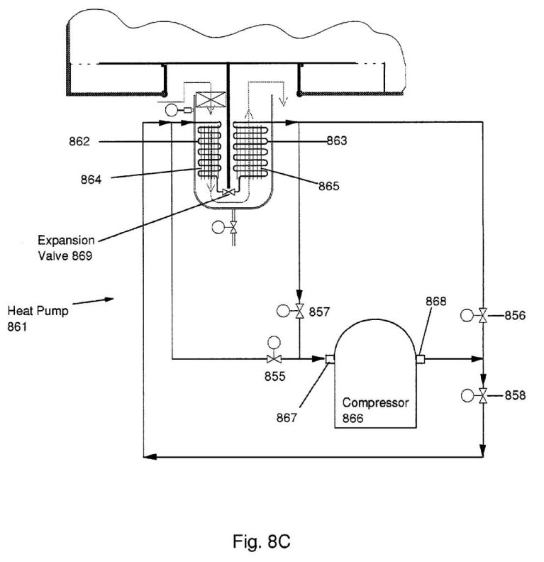
FIG. 8C shows the
operation of the embodiment of FIG. 8A during defrost mode;
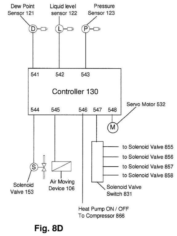
FIG. 8D shows a control
schematic for the embodiment of FIGS. 8A through 8C.
US6144013
Local humidity control system for low temperature electronic
module
Abstract -- A local humidity control system and
method are provided for a low temperature electronic device
assembly wherein a surface of the low temperature electronic
device assembly is maintained above an ambient dew point.
The local humidity control system includes a first layer of
thermal insulation at least partially surrounding and
contacting the cooled electronic device, and a second layer
of thermal insulation surrounding the first layer of thermal
insulation and the cooled electronic device in which a
volume is defined between the first and second layers of
insulation. A heater assembly interfaces with the volume to
heat the volume to a temperature sufficient to maintain the
surface of the cooled electronic device above the ambient
dew point. The heater assembly includes a thin film heater
attached to the first layer of thermal insulation to
maintain temperature of the surface above the ambient dew
point, and a wire mesh heater suspended within the volume to
lower relative humidity in the volume and inhibit the
ingress of water vapor.