John WEIGAND
Bistable Magnetic Wire
Bistable Magnetic Wire
https://en.wikipedia.org/wiki/Wiegand_effect
Wiegand effect
The Wiegand effect is a nonlinear magnetic effect, named after its discoverer John R. Wiegand, produced in specially annealed and hardened wire called Wiegand wire.[1]
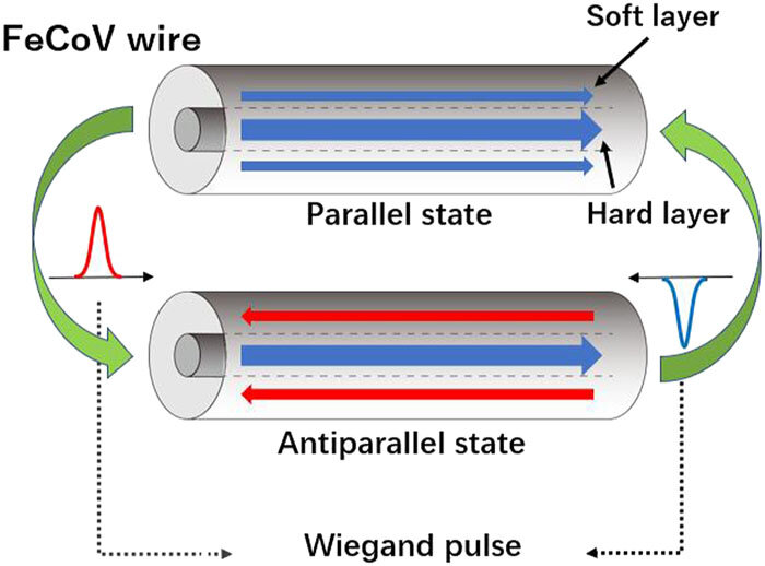
Principle of a Wiegand sensor and external magnetic field
Wiegand wire is low-carbon Vicalloy, a ferromagnetic alloy of cobalt, iron, and vanadium. Initially, the wire is fully annealed. In this state the alloy is "soft" in the magnetic sense; that is, it is attracted to magnets and so magnetic field lines will divert preferentially into the metal, but the metal retains only a very small residual field when the external field is removed.
During manufacture, to give the wire its unique magnetic properties, it is subjected to a series of twisting and untwisting operations to cold-work the outside shell of the wire while retaining a soft core within the wire, and then the wire is aged. The result is that the magnetic coercivity of the outside shell is much larger than that of the inner core. This high coercivity outer shell will retain an external magnetic field even when the field's original source is removed.
The wire now exhibits a very large magnetic hysteresis: If a magnet is brought near the wire, the high coercivity outer shell excludes the magnetic field from the inner soft core until the magnetic threshold is reached, whereupon the entire wire — both the outer shell and inner core — rapidly switches magnetisation polarity. This switchover occurs in a few microseconds, and is called the Wiegand effect.
The value of the Wiegand effect is that the switchover speed is sufficiently fast that a significant voltage can be output from a coil using a Wiegand-wire core. Because the voltage induced by a changing magnetic field is proportional to the rate of change of the field, a Wiegand-wire core can increase the output voltage of a magnetic field sensor by several orders of magnitude as compared to a similar coil with a non-Wiegand core. This higher voltage can easily be detected electronically, and when combined with the high repeatability threshold of the magnetic field switching, making the Wiegand effect useful for positional sensors.
Once the Wiegand wire has flipped magnetization, it will retain that magnetization until flipped in the other direction. Sensors and mechanisms that use the Wiegand effect must take this retention into account.
The Wiegand effect is a macroscopic extension of the Barkhausen effect, as the special treatment of the Wiegand wire causes the wire to act macroscopically as a single large magnetic domain. The numerous small high-coercivity domains in the Wiegand wire outer shell switch in an avalanche, generating the Wiegand effect's rapid magnetic field change.
Applications
Wiegand Sensors
Wiegand sensors are magnetic sensors that make use of the Wiegand effect to generate a consistent pulse every time magnetic field polarity reverses and therefore do not rely on any external voltage or current.[2] The consistency of the pulses produced by Wiegand sensors can be used to provide energy for low-power and energy-saving applications.[3] Being self-powered, Wiegand sensors have a potential in IoT applications as energy harvesters, proximity sensors, and event counters.[4][5]
Wiegand keycards
Besides sensors, the Wiegand effect is used for security keycard door locks.[6] The plastic keycard has a series of short lengths of Wiegand wire embedded in it, which encodes the key by the presence or absence of wires. A second track of wires provides a clock track. The card is read by pulling it through a slot in a reader device, which has a fixed magnetic field and a sensor coil. As each length of wire passes through the magnetic field, its magnetic state flips, which indicates a 1, and this is sensed by the coil. The absence of a wire indicates a 0. The resulting Wiegand protocol digital code is then sent to a host controller to determine whether to electrically unlock the door.
Wiegand cards are more durable and difficult to counterfeit than bar code or magnetic stripe cards. Since the keycode is permanently set into the card at manufacture by the positions of the wires, Wiegand cards can't be erased by magnetic fields or reprogrammed as magnetic stripe cards can.
Rotary encoder
Wiegand wires are used by some rotary magnetic encoders to power the multi-turn circuitry. As the encoder revolves, the Wiegand wire core coil generates a pulse of electricity sufficient to power the encoder and write the turns count to non-volatile memory. This works at any speed of rotation and eliminates the clock/gear mechanism typically associated with multi-turn encoders.[7][8]
Wheel speed sensor
Wiegand wires are fitted to the outer diameter of a wheel to measure rotational speeds. An externally mounted reading head detects the Wiegand pulses.
https://www.posital.com/en/products/wiegand-sensors/wiegand-techology.php
The “Wiegand effect” is a physical phenomenon discovered in the 1970’s by John Wiegand. Wiegand found that when a specially prepared piece of ferromagnetic alloy (the Wiegand wire) is subject to a reversing external magnetic field, it will retain its magnetic polarity up to a certain point, then suddenly ‘flip’ to the opposite polarity. This change in magnetic polarity takes place within a few microseconds. This sudden change of magnetic polarity can generate a pulse of current in a copper coil positioned close to the Wiegand wire. This event is often referred to as the Wiegand effect.
The strength and duration of the resulting pulse is independent of the rate at which the external magnetic field changes. This is what makes the Wiegand effect interesting to engineers: simple dynamos convert rotary motion into electrical energy, but their output power depends on the rotation speed; when the shaft of a dynamo turns very slowly, power levels are too low to be of much use. However, with a Wiegand wire system, the amount of electrical energy generated with each ‘flip’ of the magnetic field remains constant, however quickly – or slowly – the magnetic field changes. In POSITAL rotary encoders this reversal is generated by rotating a magnet.
How Does it Work?
B. When the wire is exposed to a moderate external field in the opposite direction, the outer layer of the wire shields the core, and both retain their original magnetic polarity. However, when the strength of the external field reaches a critical threshold, the influence of this shielding effect is overwhelmed and the polarity of the core of the wire will suddenly reverse. This sudden change in polarity creates a current pulse in the coil surrounding the wire.
C. The combination of the strengthening external field and the reversed polarity of the inner core cause the magnetic polarity of the outer shell to reverse as well.
D. As the external field diminishes, the wire retains its new polarity.
E. When the external field, now reversed, reaches the critical threshold, the core material of the Wigand wire will flip back to its original polarity, producing a current pulse in the surrounding coil.
F. This is followed quickly by a reversal of the polarity of the outer core. The wire is now back in State
A. At the beginning of the cycle, the magnetic polarity of the outer shell and the inner core and are the same.
https://www.automation.com/en-us/articles/july-2022/wiegand-wire-energy-harvesting-motion-sensing
Wiegand Wire Enables Energy Harvesting, Motion Sensing
The “Wiegand effect” was discovered almost 50 years ago and has been used successfully in several specialized applications. However, its full potential for energy harvesting and signal generation has received only limited recognition. With recent enhancements to the energy output from Wiegand devices and the emergence of a new generation of ultra-efficient electronic chips for wireless communications, the technology is showing significant promise, especially in the realm of the Internet of Things (IoT). UBITO, a member of the FRABA Group of technology companies, is leading research and development projects aimed at fulfilling this promise.
Wiegand Effect explained
The Wiegand effect is a physical phenomenon discovered in the 1970s by John Wiegand, an American inventor who found that by repeatedly stretching and twisting a piece of ferromagnetic wire, he could alter its magnetic properties. When a sample of Wiegand wire is exposed to a reversing external magnetic field, it will initially retain its original magnetic state. However, when the strength of the external field reaches a critical threshold, a region of the wire that is magnetically soft will undergo an abrupt reversal of its polarity. This transition takes place within a few microseconds and can be harnessed to induce a pulse of electric current in a fine copper coil wrapped around the wire.
The electric pulse generated by a Wiegand wire is very brief, but its strength stays nearly constant, regardless of how quickly or slowly the external magnetic field changes. This is what makes the Wiegand effect special: While simple dynamos, which also use electromagnetic induction, are effective at converting rotary motion into electrical energy, their output power varies with rotation speed. When a dynamo is turned slowly, power levels can be too low to be useful. With a Wiegand wire, however, the amount of electrical energy generated with each reversal of the magnetic field remains consistent over a wide range of speeds.
The combination of a short length of Wiegand wire and a surrounding copper coil is referred to as a Wiegand sensor. These are available commercially from UBITO in surface-mountable device (SMD) packaging.
Using energy harvesting power for innovation
“Energy harvesting” refers to technologies that extract energy from the local environment to power electronic devices. Several are available, including photovoltaics (energy from light), thermoelectric and pyroelectric effects (energy from temperature variations), and piezoelectric and electrostatic devices (energy from mechanical motion).
Wiegand sensors are also a good candidate for energy harvesting. In their basic form, these devices produce modest amounts of energy—about 200 nanojoules. However, recent developments have significantly increased energy output from Wiegand devices and opened possibilities for much more ambitious applications.
Building an energy self-sufficient IoT Node
An R&D program, carried out by a team of researchers at FRABA’s technology center and the Rhineland-Westphalia Technical University with support from the German Ministry of Science and Technology, has developed enhanced Wiegand devices that are optimized for power generation. These are called “Wiegand harvesters.” The researchers have demonstrated that a set of Wiegand harvesters (Figure 1) can generate up to 10 microjoules of energy (approximately 50 times the output from a commercial Wiegand sensor). This was sufficient to energize a low-power ultra-wide-band radio transceiver with a transmission range of 60 meters.
Energy harvesting for self-powered sensors
For small Wiegand sensors, the electrical energy produced with each polarity change, while limited, is sufficient to activate a low-power electronic counter circuit. This form of energy harvesting has been used successfully in more than a million encoders (rotation measurement instruments) built by POSITAL and other manufacturers (Figure 2).
Because of Wiegand energy harvesting, these encoders’ rotation counter systems are entirely self-powered with no need for external power sources or backup batteries, significantly reducing maintenance requirements.
Figure 2: Energy harvesting has been used successfully in encoders.
Figure 3: Wiegand sensors for rotation counting in fluid meters.
A similar principle has been used for water or gas meters. Here, a permanent magnet is mounted on the meter’s rotating shaft, close to a Wiegand sensor (Figure 3). As the shaft turns, the rotation of the magnetic field triggers abrupt polarity reversals in the Wiegand wire, inducing electric current pulses in the copper coil. As the strength and duration of each current pulse is independent of how quickly or slowly the shaft rotates, Wiegand sensors provide much higher signal- to-noise ratios than other analog magnetic sensors (e.g., Hall effect sensors). This ensures that the meter’s counter circuit receives clear and unambiguous signals with each rotation of the shaft. Energy from the electrical pulse can also be harnessed to power the rotation counter circuitry, so the counter will keep a reliable record of shaft rotations in the absence of an external energy source.
Figure 4: The presence of a large ferromagnetic (iron) body nearby can neutralize the effect of one of these magnets so the magnetic field at the Wiegand sensor is dominated by the other magnet.
Wiegand-based event triggering also has been used for tachometers for rail cars and other equipment. For this application, the Wiegand sensor is located near two magnets with the opposite polarity. The presence of a large ferromagnetic (iron) body nearby can neutralize the effect of one of these magnets so the magnetic field at the Wiegand sensor is dominated by the other magnet (N-S in Figure 4). As the ferromagnetic body rotates, it neutralizes the other stationary magnet, reversing the field (S-N) and triggering a polarity flip in the Wiegand wire (Figure 5). The benefit of Wiegand technology in this application is that it operates reliably over a wide range of rotation speeds. Moreover, with no mechanical contact between the sensor and the moving component, there is no wear, and the systems have service lifetimes of billions of operating cycles.
Figure 5: As the ferromagnetic body rotates, it neutralizes the other stationary magnet, reversing the field (S-N) and triggering a polarity flip in the Wiegand wire.
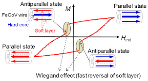
The Wiegand cycle
The mechanical process that produces Wiegand wires creates a combination of magnetically hard and soft layers in the wire, causing the wire to have a high level of magnetic hysteresis (Figure 6).
As the external magnetic field changes, the Wiegand wire will at first retain its initial polarity (Point A in Figure 6). However, when the strength of the external field reaches a critical threshold, the polarity of the magnetically soft zone of the Wiegand wire suddenly reverses (Point B). As the external field continues to strengthen, the magnetically hard zone will also reverse its polarity, so the whole wire reaches a new magnetic state (Point C). When the external field changes back toward its original polarity, a sudden reversal of the soft material will occur again (Points D, E). The wire will eventually return to its earlier state (Points F, A). These rapid changes in the magnetic polarity of the wire core induce short pulses of electrical current in the fine copper coil wrapped around the Wiegand wire (Figure 7).
Figure 6: The mechanical process that produces Wiegand wires creates a combination of magnetically hard and soft layers in the wire, causing the wire to have a high level of magnetic hysteresis.
Figure 7: Rapid changes in the magnetic polarity of the wire core induce short pulses of electrical current in the fine copper coil wrapped around the Wiegand wire.
Manufacturing Wiegand wire
Wiegand wire is produced through a process that involves annealing a spool of Vicalloy wire (an alloy of vanadium, iron, and cobalt), then simultaneously stretching and twisting the wire. This aggressive cold working alters the crystalline structure of the metal and creates two regions—an inner core and outer shell—with significantly different levels of magnetic coercivity. (Coercivity is a property of ferromagnetic materials that defines how easily the material can be magnetized by an external magnetic field. Magnetically soft materials, such as mild steel, have low coercivity and change their magnetic state easily. Magnetically hard material, such as the alloys used to make permanent magnets, will retain their magnetic state unless they are exposed to very strong external fields.) The interaction of these two regions causes the wire to have a high level of magnetic hysteresis.
The “recipe” for producing a satisfactory batch of Wiegand wire was determined by John Wiegand and his collaborators through trial and error. The machine they developed to produce Wiegand wire features a series of rotating frames that stretch, twist, and then untwist the wire at various rates. This machinery was acquired by FRABA, along with John Wiegand’s lab notes. Since then, research carried out by FRABA and its partners has automated this process and optimized it for quality and consitency (Figure 8).
https://www.youtube.com/watch?v=rpdn9XNJBuc
Wiegand Effect - The Magic of a Uniquely Useful Little Wire
https://www.machinedesign.com/mechanical-motion-systems/article/21138759/new-ways-to-put-the-wonderful-wiegand-wire-to-work
New Ways to Put the Wonderful Wiegand Wire to Work
The Wiegand effect may be used to create self-powered pulses. Wiegand systems function reliably for billions of cycles // by Tobias Best
US3892118 -- Method of manufacturing bistable magnetic device
[ PDF ]
A ferromagnetic wire is processed by being subjected to cycling torsional strain and longitudinal strain to provide a bistable magnetic wire switching device having permanently different shell and core magnetic properties. The product switches state in response to an appropriate threshold external field and does so without being held under external stress or strain.
BACKGROUND OF THE INVENTION
The magnetic device described in the above referenced applications is a ferro-magnetic wire having core and shell portions with divergent magnetic properties. As taught in said applications a preferred way of obtaining these divergent magnetic properties is to apply a torsional force to the wire so as to circumferencially strain the wire. The wire is circumferencially strained in alternate clockwise and counterclockwise directions while maintaining axial tension on the wire. The result is a wire which, it is believed, because it has a relatively harder magnetic shell and a relatively softer magnetic core, has the property that once magnetized the shell becomes a permanent magnet and the core, being softer, will be magnetically captured by the shell to provide a return path for the lines of flux generated by the shell.
An alternate explanation of the phenomenon is one that assumes there is some axial flow of the shell relative to the core during the twisting operation because the twisting operation takes place while the wire is held under tension. Under this model, the axial flow or straining of the shell results in the application of a stress to the core. Then the torsional straining (twisting) is stopped and the axial tension removed, the resulting wire is one in which there is a permanent axial tension on the core exerted by the shell which is flowed.
When the wire described in the parent applications is subjected to an increasing external magnetic field, a threshold is reached where the external magnetic field suddenly and rapidly captures the core to provide a low reluctance path for its flux. If the polarity of the external field is opposite from that of the shell, then the flux from the shell must be completed in the space around the wire. A pick-up coil will produce a pulse in response to this sudden change in the flux pattern. The change in the flux pattern occurs in response to a threshold magnetic field intensity being achieved and is substantially rate insensitive. That is, the magnitude of the output pulse is independent of the rate at which the external field increases. Similarly, there is a reverse switch in magnetic field configuration and a reverse pulse generated in the pickup coil as the magnetic field decreases. Again, the pulse output is substantially independent of the rate at which the magnetic field decreases; all that is required is that the switching threshold be passed.
Accordingly the major purpose of the invention described and claimed herein is to provide a method for manufacturing the two state wire described in the above referenced patent application.
The magnitude of the output pulse is of critical importance in determining the value of the wire and in determining the scope of applications to which the wire can be commercially put. The larger the pulse, the less will be required in the way of electronic circuity associated with the pickup coil to distinguish the pulse from various background noise. The larger the pulse, the more repeatable will be any output condition that is to be iniated or recorded by the incidence of the pulse.
According, it is a major purpose of this invention to provide a method of fabricating the wire described in the above referenced patent applications with a switching response to a threshold external magnetic field that will produce a pulse having improved signal to noise ratio and having a larger peak magnitude.
It is a related and further important purpose of this invention to provide such an improved wire as will provide the kind of switching response to the threshold magnetic field that will produce a uniform and repeatable output pulse from a pick-up coil.
BRIEF DESCRIPTION OF THE INVENTION
In brief, it has been found that a preferred mode of manufacturing the wire to produce greater magnitude, more repeatable and more uniform output pulses is to use a fine grain nickle-iron alloy having a 10 mil (0.010 inch) diameter. A one meter length of this wire is stretched four centimeters. The stretched wire is then held between two chucks at a constant tension of 450 grams. One of the two chucks is oscillated back and forth at a rate of 0.4 turns per centimeter of wire. Thus for the one metal length of wire, the chucks rotate 40 complete revolutions in one direction and then 40 complete revolutions in the other direction. This clockwise and counterclockwise rotation is repeated ten to fifteen times. The chucks are supported in a machine which maintains a constant tension of 450 grams as the rotation occurs. After this processing, the tension is removed and the one meter length of wire is cut into whatever lengths are desired (frequently about 1/2 inch each) for use in the various switching and pulse generating applications which have been developed for this wire.
DESCRIPTION OF THE PREFERRED EMBODIMENTS
The wire described in the referenced patent applications is one which when magnetized has two magnetic states. When switching between these two magnetic states, at least a portion of the flux switches from a path external of the wire to a path internal to the wire or vice versa, so that a pick up coil wound around the wire will generate a pulse. The rate at which the flux switches when the wire changes state is so fast that the electrical pulse generated by the pick-up coil is a distinctive sharp usable pulse. Furthermore, this state switching occurs in response to an external magnetic field, having a proper direction, either increasing in magnetic field intensity to above a first threshhold or decreasing in magnetic field intensity below a second threshhold. The switching of the wire, thus, is responsive to a threshhold magnetic field applied to the wire. As a result, the magnitude of the output pulse is not rate sensitive in that it is not affected by the rate at which the external triggering magnetic field increases or decreases. The use of this bistable wire for generating this distinctive, non-rate sensitive output pulse has the further advantage that the process occurs without requiring any input electrical signals or current. Thus an external permanent magnet can be used as the source of the triggering magnetic field and all that is required is that the position between the bistable magnetic wire and the external permanent magnet be increased and decreased to provide the increase of external field over the first threshhold and the decrease of external field under the second threshhold. Even where the triggering magnetic field is generated by an electric current through a coil around the wire, there is no need for other electrical inputs at the switching device.
It is believed that this bistable magnetic wire operates as it does because of the intimate physical relationship between a magnetically harder shell zone and a magnetically softer core zone. It is believed that the holding of the core under tension by the shell occurs and may be an important factor in the magnetic switching phenomenon.
As described in the referenced patent application, a method for forming a wire of the type described is constituted by (a) drawing the wire to substantially the desired size while it is maintained at a suitable elevated temperature to form a wire with a desired fine grain, and (b) work hardening the wire in a manner which provides for hardening of the wire shell while maintaining the wire core relatively soft. For example, for forming a wire composed of 48% iron and 52% nickel, the wire is drawn from a relatively heavy gauge wire (e.g., 1 to 11/2 diameter wire) by passing the wire through successive drawing stations which individually provide for a 20% reduction in the cross-sectional area of the wire at approximately 75 feet per minute. This is a standard wire drawing technique employed by the wire manufacturer.
By this first step of the manufacturing process, it is desired to form a wire with a fine grain not less than 6,000 grains and preferably with a grain size providing at least 8,000 grains per square millimeter and more desirably with a grain size providing 10,000 or more grains per square millimeter. It has been found that the effectiveness of the wire as a bi-stable switching device varies in some inverse relationship with the wire grain size and thus in some direct relationship with the number of grains per unit area. As grain size increases (from a grain size providing 10,000 grains per square millimeter) the effectiveness of the wire decreases fairly rapidly such that a wire with a grain size providing approximately 6,000 grains per square millimeter has substantially less effectiveness. As the grain size is reduced, the effectiveness of the wire is improved somewhat.
More specifically, it is believed that for a given wire diameter as the grain size is reduced the slope of the portion of the M-H curve corresponding to reversal of the core magnetism increases (becomes more verticle) and, therefore, the pulse is sharper. However, the resultant induced pulse width in the pick-up coil is reduced. Consequently, the optimum grain size depends upon the application in which the wire is used and for many applications the preferred grain size has been determined to be 10,000 grains per square millimeter for a 0.012 inch (12 mil) diameter wire.
Following the drawing operation, the wire is work hardened at room temperature to produce a relatively hard shell with relatively high retentivity and coercivity while maintaining a relatively soft core with relatively low retentivity and coercivity. In one early and experimental embodiment, it has been found that such results can be obtained by stretching the wire slightly (e.g., 21/2% for an alloy of 48% iron and 52% nickel) and thereafter circumferentially straining the wire. The circumferential straining step can be performed by twisting the wire back and forth with or without retaining a permanent twist. For example, it has been found that good results are obtained by twisting the wire 10 turns per linear inch of wire in one direction and then untwisting the wire the same amount in the opposite direction and such that the wire is in a generally untwisted state when the work hardening process is completed. Alternatively, the twisting operation could be completed with the wire is a twisted state when for example a wire of the type shown in FIG. 7 is desired which provides a helical preference to a direction of magnetic flux.
Although a number of techniques and indeed a preferred technique for manufacturing the wire of the invention described and claimed in the above referenced patent applications has been described therein, further experimentation and development work has resulted in a very substantially improved wire and in a technique for manufacturing this improved wire. The wire is improved in that it provides (1) a greater output presumably because of the greater amount of the flux generated by the magnetized wire when switched and (2) a more repeatable and uniform wire in that each segment produced has characteristics substantially more similar to that of other segments than was previously the case.
A variety of different ferro-magnetic materials may be used for the wire of this invention. And it is believed that the material involved probably must have magneto-strictive qualities. The preferred wire is a fine grain structure; 10,000 grains being the grain count in one preferred embodiment. One wire employed has a 52% nickel and a 48% iron content and was 10 mils (0.010 inches) in diameter. This type wire can be obtained as alloy No. 152 from the Driver-Harris Company.
A one meter length of wire has been used (only because it is a convenient length) for fabricating the bistable magnetic wire. In a second embodiment of this invention, this one meter length is then stretched by 4% to a length of 104 centimeters. It is preferred to stretch the wire slowly and steadily so that an even stretching occurs over the length of the wire and so that any soft spots tend to harden rather than simply neck down and provide the only area where stretching occurs. It is believed that stretching tends to align the crystals in the wire in a longitudinal direction and to provide a somewhat longitudinal magnetic path that is easier to magnetize than is a radial path. In this fashion an anisotropy is built into the wire. The 4% stretch is approximately one third of the amount of stretch that the wire will take until it breaks. Somewhat more stretching can thus be tolerated. Stretching up to six centimeters (6%) has been successfully employed while providing optimum results.
As shown in FIG. 9, the wire, after it has been stretched, is held between two chucks 120, 121. One of these chucks 120 is held to an arm 122 of a precision dynamometer 124. The dynamometer 124 is adjusted to a tension of 450 grams so that the wire is held under a constant 450 gram tension. These dynamometers are of a type used in coil winding machinery and are a standard device. The other chuck 121 is mounted to a gear 128 which operates as the pinion of a rack and pinion combination. The rack 130 is rotated back and forth by a conventional eccentric mounting to a plate 134 driven by a motor 132.
The rack 130 is moved in one direction to provide 40 turns on the one meter of wire held between the two chucks 120, 121 seen in FIG. 9. With the rack 130 moving to the left, the wire is twisted about its axis in a counterclockwise direction. At all times the action of the dynamometer 124 maintaining the tension on the wire at a constant 450 grams. After 40 turns counterclockwise the rack 130 is caused to move to the right so that the wire is untwisted. This cycle of twisting counterclockwise and untwisting clockwise is repeated 15 times.
It is believed that the result of this process is to work harden the outer portion of the wire 10 while having a minimum effect on the inner portion of the wire. The result is a magnetically harder shell area and a magnetically softer core.
It is also believed that the maintaining of the constant 450 gram tension on the wire during this process tends to cause the worked portion (that is, the shell) to migrate somwhat in an axial direction. This slight longitudinal migration of the shell 16, it is believed, tends to provide a permanent longitudinal tension on the core 14 and thus aids in the longitudinal anisotropy that facilitates the distinctive fast switching of the wire 10.
After the cycling step, the wire is released from the chucks 120, 121 and cut into the desired lengths by means of shears. It is important that the wire be cut in a fashion that avoids pinching or squeezing the wire 10. Radial compression of the wire tends to destroy the phenomenon on which this wire operation is based. Since compression of the ends can eliminate the switching effect for the length over which the ends are compressed, it is important that the wire be sheared without appreciable compression.
In a further embodiment of this invention, the same wire was employed but the initial stretch was 6% instead of 4% and thus the wire was stretched to 106 centimeters. In this further embodiment, the tension maintained during the twisting was 250 grams and the number of turns was 22 turns per meter instead of 40 turns per meter. Furthermore, the number of cycles of counterclockwise twisting and clockwise untwisting was 50 cycles instead of 15 cycles.
This further embodiment provided a wire having larger pulses where the wire segments that are employed in a switching device are in the order of 5 centimeters. The second embodiment (the 4% pre-stretch example) appears to provide better wire where the length of wire segments employed are less than 3 centimeters. In any case, there is a range of stretching, tension, number of turns per meter and number of cycles which can be employed. The preferred or optimum results will be a function of trial and error in relationship to the particular wire involved and the particular end use of the wire.
In general terms, the following considerations should be kept in mind in determining the precise method employed in manufacturing this type of bistable magnetic wire.
A 10 mil (0.010 Inch) diameter has been found to be optimum. Twelve mil diameter wire tends to produce a less distinctive, less sharp pulse. Eight mil wire tends to be too hard to control and provides less uniform results than does the 10 mil wire.
For the wire involved in these tests, a twisting of 22 turns per meter has been found to be a minimum optimum in that the amplitude of the output pulse in the wire product tends to decrease as the amount of the twisting in processing becomes less than approximately 22 turns per meter. As the number of turns per meter increases there is some increase of distortion in the output pulse from the wire product 10. At approximately 60 turns per meter the output pulse distortion appears to be too great for most purposes.
The number of times the twisting and untwisting cycle is repeated has a limit in that too much cycling causes distortion. The twisting and the cycling both affect the amount of work hardening. Thus there is some trade-off between these two operating factors. The fewer the turns per meter, the more the number of cycles of twisting and untwisting to provide optimum results. But this trade-off is within a limited range.
It appears to be of value to maintain some circumferential component of some factor (perhaps anisotropy) in order to achieve an optimum switching effect. Thus, in the examples described above, the twisting is done on one side of a start position. But it is not certain as to how important this factor is. There are some experiments in which the twisting has been, say, 11 turns counterclockwise and 22 clockwise and 22 counterclockwise and cycled through such a procedure to provide usuable results.
When a ferromagnetic wire is treated in accordance with the method of this invention, a product is provided which apparently has a two magnetic phase characteristic or at least two portions or sets of portions having different magnetic characteristics. It is believed that the two portions are approximately a core and shell portion; the shell portion being coaxial with and surrounding the core portion. The difference between the shell and core portion is created by virtue of the fact that the wire is torsionally strained. The torsional straining means that the radially outer portions of the wire are strained more than are the radially inner portions of the wire. Indeed, from a geometrical point of view, the axis of the wire is untouched by the torsional straining process.
In addition to the torsional straining of the wire, there is an axial straining of the wire. In a preferred treatment technique, there is axial straining by virtue of the pre-stretching of the wire and further axial straining by virtue of a substantial tension being maintained on the wire while it is being torsionally strained.
The various experiments performed thus far indicate that a combination of axially straining and torsional straining is required to provide the end product of this invention. The particular manner in which a wire is treated is a function of the composition of that wire and more particularly of the hardness of the wire. However, in all cases, the wire involved is a ferromagnetic wire and apparently is one that has a substantial nickel content and thus generally has a magnetostrictive parameter.
In the above examples, pre-stretching (preferably 4 to 6%) is described. In wire that is substantially harder, pre-stretching may be impossible because it may break the wire. In such a case, the tension during torsional straining should be selected large enough to result in some elongation of the wire.
The Wire Product Provided
The method described above provides a ferromagnetic wire having a generally uniform chemical composition. The wire has a magnetic central portion (herein referred to as a core) and a magnetic outer portion (herein referred to as a shell) having different net magnetic characteristics and which cooperate to form an extremely effective magnetic switching device.
An embodiment 10 of such a magnetic wire is shown in FIG. 1 and comprises a drawn wire of a ferromagnetic material having a generally circular cross section. It is preferred that the wire has a true round cross section or as close to true round as can be reasonably obtained. The magnetic wire 10 may, for example, be 5/8 long, have a diameter of 0.012 inches and be made of a commercially available wire alloy having 48% iron and 52% nickel. The wire is processed to form a relatively "soft" magnetic wire core 14 having relatively low magnetic coercivity and a relatively "hard" magnetic wire shell 16 having relatively high magnetic coercivity. Accordingly, the shell is effective to magnetically bias the magnetic core 14.
The term "coercivity" is used herein in its traditional sense to indicate the magnitude of the external magnetic field necessary to bring the net magnetization of a magnetized sample of ferromagnetic material to zero.
The relatively "soft" core 14 is magnetically anisotropic with an easy axis of magnetization substantially parallel to the axis of the wire. The relatively "hard" shell is is also magnetically anisotropic with an easy axis of magnetization substantially parallel to the axis of the wire. In FIG. 1, the shell 16 is magnetized to form north and south poles at its opposite ends. The relatively "hard" shell 16 has a coercivity sufficiently greater than that of the relatively "soft" core 14 to couple the core to the shell 16 by causing the net magnetization of the core 14 to align in an axial direction opposite to the axial direction of the net magnetization of the shell 16 as indicated in FIG. 1. When the core 14 is thus coupled to the shell, the core 14 forms a magnetic return path or shunt for the shell 16 as shown by the flux lines illustrated in FIG. 1 and a domain wall interface 18 is formed in the wire 10 between the oppositely extending lines of flux therein. The domain wall interface 18 defines the boundary between the core and shell. For simplifying the understanding of the magnetic wire 10 this domain wall 18 boundary may be thought of as having a cylindrical shape as shown in FIG. 1 although it is believed that the domain wall interface occurs along a rather irregular and indefinite magnetic transition zone in the wire. The domain wall has a thickness in the order of one micron. Thus, for the purpose of simplifying the understanding of the operation of the wire 10, the core 14 and shell 16 may be considered to be contiguous, ignoring the extremely thin magnetic transition zone that is the domain wall interface when the magnetic core 14 is magnetically coupled to the shell 16.
The core 14 has a cross-sectional area which is preferably related to the cross-sectional area of the shell 16 so that the shell 16 is effective to couple the core 14 (so that the direction of the net magnetization of the core is opposite to the direction of the net magnetization of the shell 16 and thus the core 14 provides an effective return path for most of the magnetic flux of the shell 16). The core will be deemed, herein, to be captured by the shell when the FIG. 1 coupling arrangement exists.
The net magnetization of the shell may be in either axial direction. In the absence of an external field, the higher coercivity shell will then capture the core so that the net magnetization of the core will be opposite in direction to that of the shell.
An external field can be employed to overcome the effect of the shell and to cause the magnetization of the core to switch. For example, if a sufficiently strong bar magnet is brought close to the wire segment 10, in a parallel orientation to the wire 10 and with its magnetic field polarity in opposition to the polarity of the wire shell 16, this bar magnet will capture the core 14 to reverse the direction of the net magnetization in the core 14. The switching will occur when the field strength at the core 14 from the external bar magnet exceeds in absolute magnitude the field strength at the core 14 from the shell 16. The amount by which the bar magnet field strength must exceed the shell field strength will depend on the magnitude of the core magnetic anisotropy.
The net magnetization of the core 14 is switched either (a) when an external field in opposition to the shell field provides a strong enough bias on the core to capture the core from the shell or (b) when an external field in opposition to the shell is reduced in magnitude sufficiently so that the shell captures the core from the external field. In either case, this core net magnetization reversal occurs through the process of the nucleation of a magnetic domain at one, or both, ends of the wire core and propagation (that is, movement) of a "transverse" domain wall (not the cylindrical domain wall 18) along the length of the wire. More explicitly, the transverse domain wall that is propagated during switching extends across the diameter of the core and is believed to be somewhat conical in shape. This somewhat conically shaped domain wall travels axially along the core during the process of switching and exists only during the process of switching. After this conically shaped domain wall has terminated, the domain wall 18 will either have been created (when the shell captures the core from an external field) or will have been eliminated (when an external field captures the core from the shell). It should be noted that when an external field in opposition to the shell has captured the core from the shell the direction of magnetic flux of the core will be essentially the same as the direction of the magnetic flux of the shell and thus in that state there will be no domain wall.
In general, the rate of propagation of the domain wall along the core 14 is a function of the composition, metallurgical structure, diameter and length of the wire 10 and of the strength of the magnetic field. The time involved for such nucleation and propagation is in general a function of the rate of propagation of the domain wall and the length of the wire 10.
During this process where the net magnetization of the core switches, the contribution to the external field by the shell changes materially in magnitude and rapidly in time. The result is that an appropriately placed pick-up coil will detect (read) the core reversal through generation of a pulse in the pick-up coil.
When the shell captures the core from an external field, the net change in the external field will be due to the fact that the shell field will have a path through the core and thus will be vectorially subtracted from the external field, resulting in a larger net field at the pick-up coil. Similarly, when an external field captures the core from a shell, the magnetic field due to the shell will be completed external to the wire 10 and thus will be vectorially added to the external field, resulting in a smaller net field at the pick-up coil. The result is that the direction of the flux in the pick-up coil will differ depending upon which way the core magnetization is switched.
Also it has been found that for some applications (for example, as shown in FIGS. 2 and 3) the wire can nucleate at only one end if the wire is more than some particular length. For example, a ferromagnetic wire composed of an alloy of 48% iron and 52% nickel and having a 0.012 inch diameter and processed as hereinafter described has such a maximum preferred length of approximately 0.625 inches (i.e., approximately 50 .times. diameter). The same wire excepting with a diameter of 0.030 inches has such a critical length of approximately 1.50 inches (i.e., approximately 50 .times. diameter).
Also, for example, a 0.550 inch length of the aforementioned 0.012 inch diameter wire has been found to be a useful size for the applications shown in FIGS. 2, 2a, 3 and 3a and in one sample, the shell has been found to have a coercivity of approximately 23 oersteds and the core a coercivity that is estimated at approximately 8 oersteds. Operationally, this means that an external field of 23 oersteds is required to reverse the direction of net magnetization of the shell. It also means that when the core is captured by an external field, as the external field is reduced, the core is captured by the shell when the resultant field on the core drops below 8 oersteds.
FIGS. 2 through 5 illustrate readout systems which exemplify the operation of the magnetic wire 10. In the readout system of FIG. 2 there is shown mounted in inductive relationship with the wire 10 a drive coil 20 shown encircling substantially the full length of the wire 10 and a pick-up or read coil 22 shown encircling a portion of the wire 10. An alternate embodiment shown in FIG. 2a has a pick-up coil 22 adjacent to the wire 10 and coiled normal to the orientation of the wire 10 and drive coil 20. The drive coil 20 may be used to premagnetize the entire wire 10 in a desired axial direction. During the de-energizing of the drive coil 20 there is a reduced field intensity of the coil 20 at which the shell 16 captures the core 14 by reversing the net magnetization of the core 14. Such core 14 capture takes place abruptly once the magnetic field intensity of the drive coil 20 is reduced sufficiently to permit nucleation of a magnetic domain wall in the core by the shell 16. This reversing of the net magnetization of the core 14 by the magnetic flux bias of the shell 16 occurs abruptly and at a rate that is substantially independent of the rate at which the field intensity due to the drive coil decreases.
Upon re-energization of the drive coil 20 to provide a sufficiently high magnetic bias on the core in opposition to the magnetic bias due to the shell 16, the direction of the net magnetization of the core will reverse. Thus alternate energization and de-energization of the drive coil 20 will cause the direction of the net magnetization at the core 14 to alternately switch as the core is alternately captured by drive coil 20 and by the shell 16.
FIGS. 6 and 6a illustrate the magnetization curve for the FIG. 2 embodiment. Specifically, these curves illustrate the net magnetization (M) of the wire 10 as a function of the magnitude of the field (H) due to the drive coil 20. FIG. 6 illustrates the symmetric hysteresis curve in which the external biasing field H due to the drive coil 20 is swung over both positive and negative magnitudes. FIG. 6a illustrates the hysteresis curve in the first quadrant that is generated when the external biasing field H is varied in magnitude but is always in one direction.
First, with reference to FIG. 6, assume that the FIG. 2 embodiment starts out with an unmagnetized wire 10. Then, as the external field H (due to the drive coil 20) increases, the net magnetization M in the wire will increase in the expected S shaped fashion illustrated by the segment 24 of the curve. At saturation, the net magnetization M ceases to increase as external field strength H increases and the flat portion of the curve shown in FIG. 6 is obtained. If field strength is now reduced, the net magnetization M remains substantially constant at saturation until the shell captures the core. This capture of the core by the shell occurs very abruptly and results in a sharp immediate drop of the net magnetization of the wire 10 as indicated at 28 in FIG. 6. Further decrease in the magnitude of the field H carries the M-H curve to the left until the direction of the field reverses. After the direction of the field H reverses, the net magnetization M in the wire 10 reverses. This reversal of field H direction and net magnetization M direction puts the curve in the third quadrant. An increasing negative value for the field H results in increasing negative net magnetization M producing the curve segment 25 until saturation occurs in a fashion quite analogous to that which occurs in the first quadrant. If the negative field magnitude is now decreased (that is, brought toward zero) the net magnetization of the saturated wire remains substantially constant at saturation until the external field H has an absolute magnitude of such a nature that the shell can now capture the core. At the point where the shell captures the core there is a sharp change in the net magnetization as indicated by the curve segment 29.
In overall terms, the sections 24 and 25 of the FIG. 6 curve represent the magnetization of the entire wire 10 by the field while the segments 28 and 29 of the FIG. 6 curve represent the change in magnetization in the core which occurs because of the capture of the core by the shell. This capture occurs when the bias of the magnetic field generated by the drive coil 20 has been reduced to a point where the bias due to the shell overcomes the external field bias and the anisotropy of the core and the direction of net magnetization in the core switches.
With reference now to FIG. 6a, there is illustrated the situation that occurs when the current in the drive coil 20, although it varies in magnitude, is always in the same direction so that the direction of the biasing field H is always in the same direction. For the purposes of the FIG. 6a illustration, the initial magnetizing of the wire 10 is not illustrated. Assuming that the wire 10 has been magnetized by a strong positive biasing field H, the net magnetization M will be in the saturation region 60. As the biasing field due to the drive coil 20 is decreased in magnitude the net magnetization M for the wire 10 remains fairly constant at saturation. But when the bias of the external field (due to the drive coil 20) drops sufficiently below the bias of the field due to the shell, the shell will capture the core. At this point, there is a sharp drop in the net magnetization M as indicated at 62. After the shell has captured the core, further decrease of net magnetization M of the wire 10 providing that the direction of the external field is not reversed. An increase of the external field H after the shell has captured the core, will result in an increase in net magnetization M of the wire 10 up to a point where the external field captures the core. When the external field captures the core, there occurs an abrupt increase in the net magnetization M as indicated at 64.
A comparison with FIGS. 6 and 6a is instructive. It should be noted that a change in net magnetization when the shell captures the core from the external field and when the external field captures the core from the shell results in an abrupt change in net magnetization (indicated at 28, 29, 62 and 64 in the curves). By constrast with core capture, when it is the shell that is being magnetized, the change in net magnetization is much less abrupt, as indicated at 24 and 25 of the FIG. 6 curve.
Thus, by means of this invention, an abrupt change in net magnetization is provided when the direction of magnetization of the core is reversed with the consequent result that the pulse generated within the pick-up coil 22 is a sharp, high amplitude, pulse.
In FIG. 3 there is shown a drive coil 30 and a pick-up coil 32. The pick-up coil 32 is mounted in spaced relationship to the wire 10 (rather than encircling the wire 10 as shown in FIG. 2). A suitable soft iron core 34 may be provided for the drive coil 30. A signal is induced in pick-up coil 32 in the same manner as it is induced in pick-up coil 22 of the readout system of FIG. 2 even though the pick-up coil 32 is spaced (for example, 0.020 inches) from the wire 10. Also, it has been found that the pick-up coil 32 (or the pick-up coil 22 in the readout system of FIG. 2) may be located adjacent either end of the wire 10 (as well as centrally of the wire 10 as shown in FIGS. 2 and 3) without substantially affecting the induced signal. The further form of the FIG. 3 embodiment is shown in FIG. 3a where the drive coil 30 and pick-up coil 32 are wound normal to one another about perpendicular legs of a core 36 of high permeability. Such a core can be made from a 28 % iron -- 72% nickel alloy. The core 36 serves to direct and concentrate the flux field.
In FIG. 4 there is shown a multiple bit readout system comprising a plurality of drive coils 40 spaced along the length of the wire 10 (in which case it may be desired to employ a substantially longer wire 10 than those employed in the readout systems of FIGS. 2 and 3) and a plurality of corresponding pick-up coils 42. In such a readout system, each of a plurality of segments of the wire 10 are individually operated similar to the operation of the entire wire in the readout systems of FIGS. 2 and 3. Thus, each of the drive coils 40 is operable to magnetize an adjacent segment of the signal wire 10 in either axial direction and be subsequently individually operated to momentarily reverse the magnetism in the core of the segment to induce a signal (or signals) in the corresponding pick-up coil 42. The wire 10 may therefore be used as a memory storage element for storage of binary information in each of the segments of the wire, it being seen that each wire segment comprises a bi-stable magnetic shell and a non-destructive memory core and is self-resettable after being "read."
In FIG. 5 there is shown a readout system comprising a nucleating coil 50 at one end of the wire 10, a pick-up coil 52 at the opposite end of the wire 10 and a propagating coil 54 extending substantially the full length of the wire. The propagating coil 54 may be used to premagnetize the wire 10 and thereafter used to propagate the domain wall of a magnetic domain in the core formed by the nucleation coil 50. The pick-up coil 52 may be connected to suitable circuitry to produce a readout signal as the propagating coil 54 drives the domain wall across the pick-up coil 52 and/or upon the reverse magnetization of the core by the shell when the propagating coil 54 is de-energized.
As indicated, the magnetic wire may be formed from a commercially available wire composed of an alloy of iron and nickel. The magnetic wire could also be formed from other ferromagnetic compositions and for example, could be composed of iron and cobalt or iron, nickel and cobalt where a magnetic shell with higher coercivity and more rectangular hysteresis characteristics are desired. Where a magnetic wire having an anisotropic shell with an axial easy axis of magnetization is desired, it has been found that a wire of 48% iron and 52% nickel with a diameter of between 0.001 and 0.030 inches provides a satisfactory signal with a high signal-to-noise ratio and that such a wire with a diameter in the range of approximately 0.009 to 0.015 inches provides a signal with the highest signal-to-noise ratio. The latter size wire has therefore been found to be preferable in those applications where the time interval involved for "reading" the wire is relatively unimportant. In magnetic memory application of the wire (for example, in the memory system shown and described in U.S. Pat. No. 3,067,408 of William A. Barrett, Jr. dated Dec. 4, 1962 and entitled "Magnetic Memory Circuits") it is expected that a wire having a diameter of 0.001 inches or less would provide the best results.
Also, where the magnetic wire is to be employed as a magnetic memory element, it may be desirable in some applications (for example, as described in the aforementioned U.S. Pat. No. 3,067,408) to form the shell of the wire with a permanent helical easy axis of magnetization as illustrated in FIG. 7 and in other applications (for example, as described in U.S. Pat. No. 3,370,979 of Arnold F. Schmeckenbecker dated Feb. 27, 1968 and entitled "Magnetic Films") to form the magnet shell of the wire with a circumferential easy axis of magnetization as illustrated in FIG. 8, in which event the wire may preferably be formed of a suitable ferromagnetic material providing a magnetic shell with rectangular hysteresis characteristics.
US3820090 -- BISTABLE MAGNETIC DEVICE [ PDF ]
The present invention is in a bistable magnetic wire. It is a principal aim of the present invention to provide a magnetic switching device operable to generate a readout signal with a high signal-to-noise ratio. It is another aim of the present invention to provide a new and improved self-resetting magnetic switching device. It is another aim of the present invention to provide a new and useful magnetic storage element...
US4247601 -- Switchable magnetic device [ Vicalloy ] [ PDF ]
The magnetic switching device which employs what has come to be known as the Wiegand Effect is described in US3820090. What is disclosed herein is an improved switching device made from an alloy of iron, cobalt and vanadium that provides a greater switching effect. An improved or optimized torsional strain routine for fabricating the wire switching device is also disclosed. The improved switching device provides its maximum output pulse when the wire is switched in an asymmetric fashion.
GB2076596 -- Pulse Generator [ PDF ]
A pulse generator contains a Weigand wire 1 at the location of an alternating magnetic field, whereby its direction of magnetisation is changed abruptly and continuously. The abrupt change in magnetisation direction leads to an electrical pulse voltage between the extremities of the Weigand wire 1, which voltage is tapped galvanically at said extremities, and, where necessary, is amplified. Arrangements for producing alternating magnetic fields are described including those employed with the integrated amplifier circuits of Fig. 1 and Fig. 2, (not shown).
US5177370 -- Impact sensor for vehicle safety restraint system [ PDF ]
An acceleration sensor that comprises a body of non-magnetic construction having a linear internal cavity of uniform cross section, and a pair of permanent magnetics movably mounted within such cavity with like magnetic poles opposed to each other, such that the magnetics are urged to opposite ends of the cavity by force of magnetic repulsion therebetween. At least one weigand wire is positioned externally of the cavity between the cavity ends, and has a longitudinal dimension parallel to the lineal dimension of the cavity. The weigand wire is characterized by two stable magnetic flux-generating states dependent upon application of an external magnetic field of appropriate polarity for switching between such states. An electrical coil is positioned adjacent to the weigand wire, and is responsive to switching between the two flux-generating states for generating a sensor output signal as a result of acceleration forces on either of the magnets sufficient to overcome the force of magnetic repulsion therebetween, and thus to bring one of the magnets into proximity with the wire. Additional magnets preset the weigand wire. Permeable material is used so that the magnetic force on the magnets does not change with a change in the position of the magnets.
https://www.researchgate.net/figure/Schematics-of-magnetization-states-of-the-Wiegand-wire_fig1_367978058
High precision MI sensor with low energy consumption driven by low-frequency Wiegand pulse
Ruixuan Yao Yasushi Takemura Tsuyoshi Uchiyama