Angela
BELCHER
Recycled Lead Perovskite Solar Cells
Recycled Lead Perovskite Solar Cells
http://mitei.mit.edu/news/discarded-car-batteries
January 7, 2016
Discarded
car batteries
Recovering
material for novel solar cells
Material could harvest sunlight by day, release heat on demand hours or days later
Material could harvest sunlight by day, release heat on demand hours or days later
Angela Belcher of biological engineering and materials science and engineering, Paula Hammond of chemical engineering, Po-Yen Chen PhD ’15 (now at Brown University), and others have shown that a novel, high-efficiency, low-cost solar cell can be made using lead recovered from an abundant, old-technology source: lead-acid car batteries.
Overview
MIT researchers have developed a simple procedure for making a promising type of solar cell using lead recovered from discarded lead-acid car batteries — a practice that could benefit both the environment and human health. As new lead-free car batteries come into use, old batteries would be sent to the solar industry rather than to landfills. And if production of this new, high-efficiency, low-cost solar cell takes off—as many experts think it will — manufacturers’ increased demand for lead could be met without additional lead mining and smelting. Laboratory experiments confirm that solar cells made with recycled lead work just as well as those made with high-purity, commercially available starting materials. Battery recycling could thus support production of these novel solar cells while researchers work to replace the lead with a more benign but equally effective material.
Much attention in the solar community is now focused on an emerging class of crystalline photovoltaic materials called perovskites. The reasons are clear. The starting ingredients are abundant and easily processed at low temperatures, and the fabricated solar cells can be thin, lightweight, and flexible—ideal for applying to windows, building facades, and more. And they promise to be highly efficient.
Unlike most advanced solar technologies, perovskites are rapidly fulfilling that promise. “When perovskite-based solar cells first came out, they were a few percent efficient,” says Angela Belcher, the James Mason Crafts Professor in biological engineering and materials science and engineering at MIT. “Then they were 6% efficient, then 15%, and then 20%. It was really fun to watch the efficiencies skyrocket over the course of a couple years.” Perovskite solar cells demonstrated in research labs may soon be as efficient as today’s commercial silicon-based solar cells, which have achieved current efficiencies only after many decades of intensive research and development.
Research groups are now working to scale up their laboratory prototypes and to make them less susceptible to degradation when exposed to moisture. But one concern persists: The most efficient perovskite solar cells all contain lead.
That concern caught the attention of Belcher and her colleague Paula Hammond, the David H. Koch (1962) Professor in Engineering and head of the Department of Chemical Engineering at MIT. Belcher and Hammond have spent decades developing environmentally friendly synthesis procedures to generate materials for energy applications such as batteries and solar cells. Although lead is toxic, in consumer devices it can be encapsulated in other materials so it can’t escape and contaminate the environment, and it can be recovered from retired devices and used to make new ones. But lead mining and refining raise serious health and environmental issues ranging from the release of toxic vapors and dust to high energy consumption and greenhouse gas emissions. Therefore, research teams worldwide—including Belcher and Hammond—have been actively seeking a replacement for the lead in perovskite solar cells. But so far, nothing has proved nearly as effective.
Recognizing the promise of this technology and the difficulty of replacing the lead in it, in 2013 the MIT researchers proposed an alternative. “We thought, what if we got our lead from another source?” recalls Belcher. One possibility would be discarded lead-acid car batteries. Today, old car batteries are recycled, with most of the lead used to produce new batteries. But battery technology is changing rapidly, and the future will likely bring new, more efficient options. At that point, the 250 million lead-acid batteries in US cars today will become waste—and that could cause environmental problems.
“If we could recover the lead in those batteries and use it to make perovskite solar cells, it’d be a win-win situation,” says Belcher.
Recovering and processing materials
According to Belcher, recovering lead from a lead-acid battery and turning it into a perovskite solar cell involves “a very, very simple procedure” — so simple that she and her colleagues posted a video of exactly how to do it. The sequence of steps is illustrated in the diagram below. The first step — getting the lead out of the car battery—might seem a simple proposition. Just remove the battery from the car, cut it open with a saw, and scrape the lead off the two electrodes. But opening a battery is extremely dangerous due to the sulfuric acid and toxic lead inside it. (In fact, when Belcher learned that high school students were recreating the procedure for science fair projects, she had her team delete that section of the instructional video.) In the end, Po-Yen Chen PhD ’15, then a chemical engineering graduate student and an Eni-MIT Energy Fellow and now a postdoc at Brown University, arranged to have a battery-recycling center near his home in Taiwan perform the disassembly process.
Using recycled car batteries to synthesize perovskite for solar cells
This figure shows how to synthesize lead iodide perovskite from a lead-acid battery. The simple process calls for three main steps: harvesting material from the anodes and cathodes of the car battery (shown in red); synthesizing lead iodide from the collected materials (blue); and depositing the perovskite film (green).
Back at MIT, clad in protective clothing and working inside a chemical hood, the researchers carefully scraped material off the electrodes and then followed the steps in the illustration to synthesize the lead iodide powder they needed. They then dissolved the powder in a solvent and dropped it onto a spinning disk made of a transparent conducting material, where it spread out to form a thin film of perovskite. After performing a few more processing steps, they integrated the perovskite film into a functional solar cell that successfully converted sunlight into electricity.
Penalty for using recycled lead?
The simple procedure for recovering and processing the lead and making a solar cell could easily be scaled up and commercialized. But Belcher and Hammond knew that solar cell manufacturers would have a question: Is there any penalty for using recycled materials instead of high-quality lead iodide purchased from a chemical company?
To answer that question, the researchers decided to make some solar cells using recycled materials and some using commercially available materials and then compare the performance of the two versions. They don’t claim to be experts at making perovskite solar cells optimized for maximum efficiency. But if the cells they made using the two starting materials performed equally well, then “people who are skilled in fine-tuning these solar cells to get 20% efficiencies would be able to use our material and get the same efficiencies,” reasoned Belcher.
The researchers began by evaluating the light-harvesting capability of the perovskite thin films made from car batteries and from high-purity commercial lead iodide. In a variety of tests, the films displayed the same nanocrystalline structure and identical light-absorption capability. Indeed, the films’ ability to absorb light at different wavelengths was the same.
They then tested solar cells they had fabricated from the two types of perovskite and found that their photovoltaic performance was similar. One measure of interest is power conversion efficiency (PCE), which is the fraction of the incoming solar power that comes out as electrical power. The figure below shows PCE measurements in 10 of the solar cells fabricated from high-purity lead iodide and 10 fabricated from car batteries. Because efficiency measurements in these types of devices can vary widely, the figure presents not only the highest PCE achieved but also the average over the entire batch of devices. The performance of the two types of solar cells is almost identical. “So device quality doesn’t suffer from the use of materials recovered from spent car batteries,” says Belcher.
Power conversion efficiency of fabricated solar cells
This figure shows power conversion efficiency — the fraction of incoming solar power converted to electricity — in solar cells that the researchers fabricated using starting materials purchased from a vendor (left) and recovered from a spent lead-acid car battery. In each case, the gray bar shows the average efficiency of 10 devices, while the blue bar shows the highest efficiency achieved in a single device. Performance in the two groups of devices is essentially the same, confirming that using recycled material does not compromise device quality.
Taken together, these results were extremely promising — but they were based on solar cells made from a single discarded car battery. Might the outcome be different using a different battery? For example, they were able to recover more than 95% of the usable lead in their battery. Would that fraction be lower in an older battery? And might the quality or purity of the recovered lead differ?
To find out, the researchers returned to the Taiwanese recycling center and bought three more batteries. The first had been operating for six months, the second for two years, and the third for four years. They then followed the same procedures to recover and synthesize the lead iodide and fabricate and test solar cells made with it. The outcome was the same—with one exception. In the older batteries, some of the lead occurs in the form of lead sulfate — a result of reactions with the sulfuric acid electrolyte. But they found that their original procedures were effective in recovering the lead from the lead sulfate as well as from the other compounds inside the batteries.
Based on their results, Belcher and Hammond concluded that recycled lead could be integrated into any type of process that researchers are using to fabricate perovskite-based solar cells—and indeed to make other types of lead-containing solar cells, light-emitting diodes, piezoelectric devices, and more.
Potential economic impact
A simple economic analysis shows that the proposed battery-to-solar-cell procedure could have a substantial impact. Assuming that the perovskite thin film is just half a micrometer thick, the researchers calculate that a single lead-acid car battery could supply enough lead for the fabrication of more than 700 square meters of perovskite solar cells. If the cells achieve 15% efficiency (a conservative assumption today), those solar cells would together provide enough electricity to power about 14 households in Cambridge, Massachusetts, or about 30 households in sunny Las Vegas, Nevada. Powering the whole United States would take about 12.2 million recycled car batteries, fabricated into 8,634 square kilometers of perovskite solar panels operating under conditions similar to those in Nevada.
In the long term, of course, the best approach would be to find an effective, nontoxic replacement for the lead. Belcher and Hammond continue to search for a suitable substitute, performing theoretical and experimental studies with various types of atoms. At the same time, they have begun testing the impact of another approach: replacing a portion of the lead with another material that may not perform as well but is more environmentally friendly. Already they’ve had promising results, achieving some “pretty decent efficiencies,” says Belcher. The combination of their two approaches — using recycled lead and reducing the amount required — could ease near-term environmental and health concerns while Belcher, Hammond, and others develop the best possible chemistry for this novel solar technology.
P.-Y. Chen, J. Qi, M.T. Klug, X. Dang, P.T. Hammond, and A.M. Belcher. “Environmentally responsible fabrication of efficient perovskite solar cells from recycled car batteries.” Energy & Environmental Science, vol. 7, pp. 3659–3665, 2014.
P.-Y. Chen, J. Qi, M.T. Klug, X. Dang, P.T. Hammond, and A.M. Belcher. “Response to the comments on ‘Environmentally responsible fabrication of efficient perovskite solar cells from recycled car batteries’ by Po-Yen Chen, Jifa Qi, Matthew T. Klug, Xiangnan Dang, Paula T. Hammond, and Angela M. Belcher published in Energy Environ. Sci. in 2014.” Energy & Environmental Science, vol. 8, pp. 1618–1625, 2015.


https://www.youtube.com/watch?v=LP9HmTrUms0&feature=youtu.be
Recycling
old batteries into solar cells
Massachusetts Institute of Technology (MIT)
A system proposed by researchers at MIT would recycle materials from discarded car batteries — a potential source of lead pollution — into new, long-lasting solar panels that provide emissions-free power.

http://pubs.rsc.org/en/content/articlelanding/ee/2014/c4ee00965g#!divAbstract
Energy Environ. Sci., 2014,7, 3659-3665
DOI: 10.1039/C4EE00965G
Environmentally
responsible fabrication of efficient perovskite solar
cells from recycled car batteries
Po-Yen Chen, Jifa Qi, Matthew T. Klug, Xiangnan Dang, Paula T. Hammond and Angela M. Belcher
Po-Yen Chen, Jifa Qi, Matthew T. Klug, Xiangnan Dang, Paula T. Hammond and Angela M. Belcher
Organolead halide perovskite solar cells (PSCs) show great promise as a new large-scale and cost-competitive photovoltaic technology. Power conversion efficiencies over 15% to 19% have been achieved within 18 to 24 months of development, and thus perovskite materials have attracted great attention in photovoltaic research. However, the manufacture of PSCs raises environmental concerns regarding the over-production of raw lead ore, which has harmful health and ecological effects. Herein, we report an environmentally responsible process to fabricate efficient PSCs by reusing car batteries to simultaneously avoid the disposal of toxic battery materials and provide alternative, readily available lead sources for PSCs. Perovskite films, assembled using materials sourced from either recycled battery materials or high-purity commercial reagents, show the same material characteristics (i.e., crystallinity, morphology, optical absorption, and photoluminescence properties) and identical photovoltaic performance (i.e., photovoltaic parameters and resistances of electron recombination), indicating the practical feasibility of recycling car batteries for lead-based PSCs.
http://onlinelibrary.wiley.com/doi/10.1002/adma.201200114/abstract
DOI: 10.1002/adma.201200114
Biotemplated
Synthesis of Perovskite Nanomaterials for Solar Energy
Conversion
A synthetic method of using genetically engineered M13 virus to mineralize perovskite nanomaterials, particularly strontium titanate (STO) and bismuth ferrite (BFO), is presented. Genetically engineered viruses provide effective templates for perovskite nanomaterials. The virus-templated nanocrystals are small in size, highly crystalline, and show photocatalytic and photovoltaic properties.
US2013266809
BIOTEMPLATED PEROVSKITE NANOMATERIALS
Inventor: NUERAJI
NUERXIATI / BELCHER ANGELA BIOTEMPLATED PEROVSKITE NANOMATERIALS
TECHNICAL FIELD
[0002] This invention relates to biotemplated nanomaterials and methods of making and using them.
BACKGROUND
[0003] Perovskite materials have attracted wide-spread attention due to their catalytic, ferroelectric, and ferromagnetic properties as well as their application in superconductors, thermoelectrics, and fuel cells. Due to their unique ferroelectric and semiconductor properties, researchers are investigating the photovoltaic and photocatalytic properties of perovskite materials. Nanoscaled perovskite materials exhibit improved properties over bulk materials, and their unique characteristics are under investigation. However, using conventional methods to synthesize perovskite nanomaterials of small size and high crystallinity is difficult, and preparing them with different morphologies under environmentally friendly conditions presents an even greater challenge.
[0004] Single crystal strontium titanate is well-known photocatalyst for producing hydrogen without applying bias since it has high conduction band and chemical stability. However, the band gap of strontium titanate is in UV region similar to most perovskite materials and limits its application. Therefore, it is very important to develop a technique to fabricate the strontium titanate nanowires with visible light absorption.
SUMMARY
[0005] A general method for biomimetic mineralization of perovskite nanomaterials would present unique opportunities.
[0006] In one aspect, a method of making a nanomaterial includes forming a perovskite in the presence of a biotemplate having affinity for a metal ion.
[0007] The biotemplate can include a virus particle. The virus particle can be an M13 bacteriophage. Forming the perovskite can include forming an aqueous mixture including the biotemplate, a first inorganic ion, and a second inorganic ion. The method can further include forming an ion source including the first inorganic ion and the second inorganic ion before forming the aqueous mixture. The method can further include adjusting the pH of the aqueous mixture and incubating the aqueous mixture for a predetermined time at a predetermined temperature. The method can further include calcining the reaction products after incubating the aqueous mixture.
[0008] The perovskite can have the formula (I):
[0000]
AxA′1-xByB′1-yO3±δ (I)
[0000] where each of A and A′, independently, is a rare earth, alkaline earth metal, or alkali metal; each of B and B′, independently, is a transition metal; x is in the range of 0 to 1; y is in the range of 0 to 1; and δ is in the range of 0 to 1.
[0009] A and A′, independently, can be selected from the group consisting of Mg, Ca, Sr, Ba, Pb, and Bi. B and B′, independently, can be selected from the group consisting of Ti, Zr, V, Nb, Mn, Fe, Ru, Co, Rh, Ni, Pd, Pt, Al, and Mg. The perovskite can be a strontium titanate; or the perovskite can be a bismuth ferrite.
[0010] In other embodiments, the perovskite can be a tantalum oxide, tantalum oxynitride or tantalum nitride, or compounds derived therefrom. For example, the perovskite can be sodium tantalate, zirconium oxide/tantalum oxynitride, zirconium tantalum oxynitride, tantalum oxynitride, tantalum nitride, or zirconium tantalum nitride.
[0011] In another aspect, a biotemplated nanomaterial includes interconnected crystalline perovskite nanoparticles.
[0012] The nanomaterial can be elongated in shape. The nanoparticles can have a particle size of no greater than about 50 nm, no greater than about 40 nm, no greater than about 30 nm, no greater than about 20 nm, or no greater than about 10 nm. The nanomaterial can have a diameter of no greater than about 100 nm, no greater than about 80 nm, no greater than about 60 nm, no greater than about 40 nm, or no greater than about 20 nm. In some cases, the nanoparticles can have a particle size of no greater than about 10 nm, and the nanomaterial has a diameter of no greater than about 20 nm. The nanomaterial can have a length of greater than 500 nm.
[0013] The nanomaterial can include strontium titanate; or the nanomaterial can include bismuth ferrite.
[0014] In another aspect, a photocatalyst includes a biotemplated nanomaterial as described above.
[0015] In another aspect, a photovoltaic device includes a biotemplated nanomaterial as described above.
[0016] In certain embodiments, the biotemplated nanomaterials can be post-treated with ammonia gas.
[0017] Other aspects, embodiments, and features will be apparent from the following description, the drawings, and the claims.
BRIEF DESCRIPTION OF THE DRAWINGS
[0018] FIGS. 1A and 1B are schematic depictions of nano structures and a method of making them.
[0019] FIG. 2A shows a TEM image of SrTi(EG) precursor-incubated viruses. FIGS. 2B and 2C show TEM images of virus-templated STO nanowires. FIG. 2D shows a HRTEM image of virus-templated STO nanowires, and FIG. 2E shows an XRD pattern of virus-templated STO nanowires.
[0020] FIG. 3 is a plot showing the zeta potential of the AEEE virus at different pH values.
[0021] FIG. 4 shows the XRD pattern of virus-templated STO nanowires synthesized at pH 5 without adding hydrogen peroxide, containing impurities of SrCO3.
[0022] FIG. 5 XRD pattern of virus-templated STO nanowires synthesized at pH 6 without adding hydrogen peroxide, containing impurities of SrCO3.
[0023] FIG. 6 shows an optical absorption spectrum of virus-templated BFO nanoparticles.
[0024] FIG. 7 is a TEM image of wild type M13 virus-templated STO nanoparticles.
[0025] FIG. 8 shows the XRD pattern of wild type M13 virus-templated STO nanoparticles.
[0026] FIG. 9 is a TEM image of free STO nanoparticles without M13 virus.
[0027] FIG. 10 shows the XRD pattern of STO nanoparticles without M13 virus.
[0028] FIG. 11 shows the magnetic properties of virus-templated BFO nanoparticles at 5K and 300K.
[0029] FIG. 12A shows a TEM image of BiFe(EG)-incubated viruses before heat treatment at 600° C. FIGS. 12B-12C show HRTEM images of virus-templated BFO nanoparticles after heat treatment at 600° C. FIG. 12D shows XRD pattern of virus-templated BFO nanoparticles after heat treatment at 600° C.
[0030] FIG. 13A is an energy band diagram for hydrogen production of dye-sensitized STO under visible light irradiation. FIG. 13B illustrates hydrogen gas production by water-splitting utilizing virus-templated STO nanowires deposited with Pt nanoparticles under UV irradiation (red line) and visible light irradiation with dye-sensitization (blue line).
[0031] FIG. 14A is a schematic diagram for a liquid junction solar cell including BFO nanoparticles. FIG. 14B illustrates photovoltaic properties of a solar cell using virus-templated BFO nanoparticles as photoanode.
[0032] FIG. 15 is a photograph depicting the equipment for the post-treatment of biotemplated nanomaterials using ammonia gas flow.
[0033] FIG. 16 is a photograph of the comparison between various STO products after treated by ammonia.
[0034] FIG. 17A is a graph depicting the XPS result confirms nitrogen doping onto the STO surface. FIG. 17B is a graph depicting the XRD comparison between a STO without treatment and 700° C. treatment.
[0035] FIG. 18 is a graph depicting the hydrogen evolutions based on various temperatures of treatment under visible light.
[0036] FIG. 19 is a photograph depicting various tantalum materials.
[0037] FIG. 20 is a graph depicting the hydrogen evolutions based on various tantalum materials under visible light.
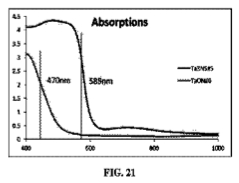
[0038] FIG. 21 is a graph depicting the absorption spectrum for Ta3N5 and TaON.


DETAILED DESCRIPTION
[0039] Biological systems provide an ideal environment for synthesizing natural minerals with control of morphology and crystal structure; expanding biological synthesis to non-natural materials while maintaining such control has been the focus of recent study. M13 bacteriophage is a diverse bio-template that has been genetically engineered for synthesizing nanomaterials that can be used to make functional devices. Particularly, metal, metal alloy, and semiconductor nanowires have been assembled and nucleated on M13 viruses. However, biological synthesis of ternary metal oxide nanomaterials is challenging as it requires matching reaction rates of multiple precursors.
[0040] A biotemplated nanomaterial can include an inorganic material. In making the biotemplated nanomaterial, the biotemplate can serve one or more of the following functions: serving as a nucleation site for nanoparticles of the inorganic material, and providing a nanoscale scaffold on which the nanoparticles are assembled into a larger nanostructure.
[0041] A nanomaterial is a material including particles having at least one dimension on the nanometer scale, i.e., from less than 1 nm to 1,000 nm. The particles can have any shape, e.g., spheres, rods, wires, tubes, or other regular shapes; or the particles can have irregular shapes. A nanomaterial can have one or more dimensions at the nanometer scale while one or more other dimensions is larger than the nanometer scale; for example, a nanowire can have a diameter that is measured in nanometers, and a length that is measured in micrometers.
[0042] A structural feature of the biotemplate can have affinity for the inorganic material and/or precursors of the inorganic material. This structural feature can be small in size compared to the overall biotemplate, e.g., on the molecular scale, such as approximately 1 to approximately 100 nm or approximately 1 to approximately 10 nm in size.
[0043] The biotemplate can be any nanoscale biological structure, including but not limited to a virus particle, a protein, a nucleic acid, a carbohydrate, or a cell. The biotemplate can include a complex of biological structures, for example, a complex of proteins, a complex of nucleic acids (e.g., a double stranded nucleic, or a nucleic acid nanostructure), a complex of proteins and nucleic acids, and the like.
[0044] In some cases, the biotemplate includes more than instance of a structural feature. For example, a virus particle can include many copies of a particular protein; a nucleic acid can include repeating nucleotide sequences; a protein can include a repeating structural motif; a protein complex can include multiple monomers of the same protein. The repeating structural feature can function in forming the biotemplated nanomaterial, for example, by providing a nucleation site for precursors of the inorganic material to be converted to nanoparticles, and/or for nanoparticles of the inorganic material to bind to the biotemplate.
[0045] In addition to structural features on the scale of approximately 1 to approximately 100 nm or approximately 1 to approximately 10 nm in size which can help to nucleate and/or bind nanoparticles of the inorganic material, the biotemplate can have structural features at a larger scale, such as approximately 100 nm to approximately 1,000 nm or longer. For example, the overall dimensions (e.g., length, width, and height, and/or when applicable, diameter) of the biotemplate can be at this scale. The biotemplated nanomaterial can thus include structural features at this scale. Accordingly, the biotemplated nanomaterial can include a plurality of nanoparticles of inorganic material (which may be crystalline nanoparticles), for example at a scale of approximately 1 to approximately 100 nm, approximately 1 to approximately 10 nm, or approximately 10 to approximately 100 nm in size, the nanoparticles being joined or interconnected by inorganic material, such that an aggregate nanoparticle can have dimensions of approximately 100 nm to approximately 1,000 nm or longer.
[0046] With regard to FIG. 1A, nanostructure 100 includes biotemplate 110 and a plurality of nanoparticles 140 on a surface of biotemplate 110. In making nanostructure 100, biotemplate 110 has surface groups 120 that can interact with nanoparticle precursors 130. (In FIG. 1, biotemplate 110 is labeled pVIII major coat proteins; however, as discussed below, the biotemplate is not limited to M13 virus or its pVIII major coat proteins). Under appropriate conditions, precursors 130 are converted to nanoparticles 140 on a surface of biotemplate 110.
[0047] A synthetic method of using a biotemplate to mineralize nanomaterials is described. The biotemplate can be a genetically engineered virus particle (e.g., an M13 virus particle). The nanomaterials can advantageously be a perovskite nanomaterial, such as strontium titanate (STO), bismuth ferrite (BFO), sodium tantalate (NaTaO3), zirconium oxide/tantalum oxynitride (ZrO—TaON), zirconium tantalum oxynitride (Zr—TaON), tantalum oxynitride (TaON), tantalum nitride (Ta3N5), or zirconium tantalum nitride (Zr—Ta3N5). Genetic engineering can provide a virus particle having surface groups that have affinity for nanomaterials and/or nanomaterial precursors. These surface groups provide sites for nanoparticles to nucleate and bind, i.e., they serve a templating function.
[0048] M13 bacteriophage can serve as a template for nanoparticle growth. See, for example, US Patent Application Publication No. 2011/0124488, and Ki Tae Nam, Dong-Wan Kim, P. J. Y. Science 2006, 312, 885, each of which is incorporated by reference in its entirety. Protein engineering techniques (e.g., phage display) can produce a virus that has a protein coat with binding affinity for a desired target material, e.g., an inorganic material such as a metal or a metal oxide. The protein coat protein can have a metal binding motif, which, for example, can be a negatively charged motif, e.g., tetraglutamate or a peptide with a binding affinity to a metal. For example, the motif can be a 12-amino acid peptide with a high affinity for Au. In one example, engineered M13 virus particles allowed control of the assembly of nanowires of Co3O4 with a small percentage of Au dopant. Id.
[0049] While M13 bacteriophage can have a major coat protein with a motif that binds specific metals, the motif can also block binding of other metals. For example, tetraglutamate can interact with various metal ions but blocks interaction with Au due to electrostatic repulsion. See, for example, Ki Tae Nam, Dong-Wan Kim, P. J. Y. Science 2006, 312, 885, which is incorporated by reference in its entirety.
[0050] The filamentous body of M13 virus includes about 2700 identical copies of the major coat protein pVIII (FIG. 1B). Genetically engineered viruses provide effective templates for perovskite nanomaterials. In particular, when the amino acid sequence AEEE is expressed at the N-terminus of each pVIII, the result is a site with high charge density (under appropriate conditions) to interact with cationic metal precursors.
[0051] Virus-templated nanocrystals can be small in size, highly crystalline, and show photocatalytic and photovoltaic properties. Virus-templated STO nanowires catalyze production hydrogen gas efficiently under both UV and visible (with dye-sensitization) irradiation. Photovoltaic performance of virus-mineralized BFO nanoparticles is also described.
[0052] A perovskite is an inorganic material having the same crystal structure as the mineral perovskite, i.e., CaTiO3. As used herein, “perovskite” refers generally to any member of the class of materials having that crystal structure, and not to the mineral specifically.
[0053] In general, a perovskite can have the formula (I):
[0000]
AxA′1-xByB′1-yO3±δ (I)
[0000] where each of A and A′, independently, is a rare earth, alkaline earth metal, or alkali metal, x is in the range of 0 to 1, each of B and B′, independently, is a transition metal, y is in the range of 0 to 1, and δ is in the range of 0 to 1. δ can represent the average number of oxygen-site vacancies (i.e., −δ) or surpluses (i.e., +δ); in some cases, δ is in the range of 0 to 0.5, 0 to 0.25, 0 to 0.15, 0 to 0.1, or 0 to 0.05. For clarity, it is noted that in formula (I), B and B′ do not represent the element boron, but instead are symbols that each independently represent a transition metal. In some cases, δ can be approximately zero, i.e., the number of oxygen-site vacancies or surpluses is effectively zero. The material can in some cases have the formula AByB′1-yO3 (i.e., when x is 1 and δ is 0); AxA′1-xBO3 (i.e., when y is 1 and δ is 0); or ABO3 (i.e., when x is 1, y is 1 and δ is 0).
[0054] Rare earth metals include Sc, Y, La, Ce, Pr, Nd, Pm, Sm, Eu, Gd, Tb, Dy, Ho, Er, Tm, Yb, or Lu. Alkaline earth metals include Be, Mg, Ca, Sr, Ba, and Ra. Alkali metals include Li, Na, K, Rb, and Cs. Transition metals include Sc, Ti, V, Cr, Mn, Fe, Co, Ni, Cu, Zn, Y, Zr, Nb, Mo, Tc, Ru, Rh, Pd, Ag, Cd, Hf, Ta, W, Re, Os, Ir, Pt, Au, or Hg. Particularly useful alkaline earth metals can include Ca, Sr, and Ba. Particularly useful transition metals can include first-row transition metals, for example, Cr, Mn, Fe, Co, Ni, and Cu. Representative materials of formula (I) include calcium titanate (CaTiO3), barium titanate (BaTiO3), strontium titanate (SrTiO3), barium ferrite (BaFeO3), KTaO3, NaNbO3, PbTiO3, LaMnO3, SrZrO3, SrHfO3, SrSnO3, SrFeO3, BaZrO3, BaHfO3, KNbO3, BaSnO3, EuTiO3, RbTaO3, GdFeO3, PbHfO3, LaCrO3, PbZrO3, or LiNbO3.
[0055] In making the biotemplated nanomaterial, in general, a biotemplate solution (typically, an aqueous solution) is combined with inorganic precursors of a desired material. The inorganic precursors can be metal ion sources compatible with an aqueous solution, for example, salts of A, A′, B, and B′ atoms. Metal ion salts can be combined into a precursor composition, for example a solution including each of the metal ions to be included in the desired material, and the precursor composition then combined with the biotemplate solution. The precursors and biotemplate are then allowed to react for a period of time at a desired temperature and at a desired pH. A further incubation (e.g., at a different temperature) can also be performed. The product of this reaction can then be calcined, i.e., heated at a temperature in the range of 100-800° C. for a period of time. Calcination can reduce or remove organic material (e.g., the biotemplate) from the inorganic nanomaterial.
EXAMPLES
Synthesis of Peroskite Nanomaterials Using M13 Virus
Experimental
[0056] Strontium chloride (SrCl2.6H2O), titanium chloride (TiCl4), bismuth nitrate (Bi(NO3)3.5H2O), iron nitrate (Fe(NO3)3.9H2O) and ethylene glycol (EG) were purchased from Sigma Aldrich. Deionized water (DI water) was used to prepare all solutions.
[0057] To prepare strontium titanium ethylene glycolate (SrTi(EG)) precursor, equal molar ratio of SrCl2 and TiCl4 were dissolved into ethylene glycol under continuous stiffing. To prepare bismuth iron ethylene glycolate (BiFe(EG)) precursor, equal molar ratio of Bi(NO3)3 and Fe(NO3)3 were dissolved into ethylene glycol under continuous stiffing. STO nanowires were synthesized by addition of SrTi(EG) precursor into virus solution. In a typical synthesis, 0.1 ml of the precursors were mixed with 10 ml of 10<12 >pfu (plaque forming units or number of virus particles) of virus solution at neutral pH, and then sodium hydroxide was further added to the solution and heated at 80° C. for 4 hours. In a typical synthesis of BFO, 0.1 ml of the BiFe(EG) precursor was added to 10 ml of 10<12 >pfu of virus solution. The solution was incubated for at least one day. Then the reactant of BiFe(EG)-incubated virus was heated at 600° C. for one hour.
[0058] Hydrogen evolution test: Photodeposition method was applied to reduce platinum ions on the surface of STO nanowires using UV-lamp. 0.5 wt % of chloroplatic acid was added to STO dispersed ethanol solution. Then the mixture was exposed to UV-lamp (100 watts) under stiffing condition. 1) Under UV light: 0.05 g of STO nanowires co-deposited with platinum nanoparticles (0.5 wt %) was added to 60 ml of the mixture of methanol and water (volume ratio 1:1.4). 2) Under visible light: 0.06 g of STO nanowires co-deposited with platinum nanoparticles (0.5 wt %) was added to 30 ml of 15% diethanol amine aqueous solution containing 0.5 mM Eosin Y. Then, the solution was purged with argon for at least 30 minutes. Before irradiation, gas chromatography (Agilent, 7890A, TCD, Ar carrier) was utilized to confirm the absence of oxygen and hydrogen gas in the head space. At each injection, 250 ml of gas was tested after irradiation with varied time using mercury lamp (100 watts). For visible light irradiation, a UV cut-off filter was used to block wavelengths shorter than 400 nm.
[0059] Photovoltaic performance: thin film of BFO nanoparticles (10 mm thick) was constructed by doctor-blading technique. The counter-electrode was 100-nm-thick platinum, sputtered on an ITO substrate (Delta Technologies). The electrolyte was a solution of 0.6 M 1-butyl-3-methylimidazolium iodide (Sigma Aldrich), 0.03 M I2 (Sigma Aldrich), 0.10 M guanidinium thiocyanate (Sigma Aldrich) and 0.5 M 4-tert-butyl pyridine (Sigma Aldrich) in a mixture of acetonitrile and valeronitrile (volume ratio, 85:15). I-V curves of the films were measured under dark and light illumination with an AM1.5 light source (100 mW cm<2>).
Results and Discussion
[0060] In the biotemplated synthesis of STO nanowires, virus solution was first incubated with strontium titanium ethylene glycolate (SrTi(EG)) precursors. The interaction between viruses and precursors was demonstrated by using transmission electron microscopy (TEM) (FIG. 2A) which shows staining of the virus with electron dense metal cations. Then the pH of the solution was changed to pH 10 and the temperature was raised to 80° C., allowing for the hydrolysis and condensation of STO nanowires on the virus. The virus-templated STO nanowires were characterized by high resolution transmission electron microscopy (HRTEM) (FIG. 2B-2D). Each STO nanoparticle was only around 5 nm in diameter and with cubic crystalline structure. High negative charge density provided by carboxylate ions on the surface of virus favors the formation of small nanoparticles. The highly crystalline structure was also confirmed by X-ray diffraction (XRD) (FIG. 2E).
[0061] Biotemplated synthesis of STO was optimized in terms of temperature, concentration of the precursors, and pH. At low temperatures (50° C. and 60° C.), no crystalline structure was found. The cubic crystalline structure of STO was formed at 80° C., which is the critical temperature to both accelerate the condensation and start STO nanocrystal nucleation and growth. The concentration of SrTi(EG) precursor for successful nanowire formation was between 0.1 mM and 1 mM. When the concentration of precursor was higher than 1 mM, homogeneous nucleation occurred and out-competed the virus-templating. The effect of the pH was also investigated. The zeta-potential of virus showed that the pI (isoelectric point) of AEEE virus was around 4 (FIG. 3). At pH lower than 4 the surface of the virus was positively charged, when incubated with SrTiEG precursors no stained viruses were formed indicating that there was no interaction between viruses and precursors. At pH higher than 4, the electrostatic interaction between viruses and precursors was demonstrated by increased electron density visualized on the viruses. However, at pH 5 ̃7, due to the low hydrolysis reaction rate, both STO and strontium carbonate were observed with or without addition of oxidants (hydrogen peroxide) (FIGS. 4-5). At pH 10, the virus-templated nanowires showed only the perovskite structured STO. As the control experiments, we examined the growth of STO using non-genetically modified M13 virus (wildtype) and also performed the reactions without the addition of the virus. FIGS. 7 and 8 clearly show discrete nanoparticles grown on wild type virus, which are different from AEEE virus templated STO. Wild type virus contains fewer carboxyl groups and is less effective at nucleating STO, resulting in nanoparticles that are larger than those prepared on genetically modified virus template (AEEE). On the other hand, in the absence of the virus (FIGS. 9 and 10), nanoparticles are polydisperse and do not show wire-like assembly. Compared with several studies that showed the carboxyl groups act as the reaction sites for mineralization of perovskite materials using the ethylene glycol precursors, the results demonstrated that the AEEE-genetically modified virus, rich in carboxyl groups, serves as an ideal template for the formation of nanowires of perovskite materials.
[0062] To synthesize BFO nanoparticles, the virus solution was incubated with bismuth iron ethylene glycolate (BiFe(EG)) precursor. The interaction between viruses and precursors was demonstrated by TEM (FIG. 12A). Then the BiFe(EG)-incubated virus was heated at 600° C. allowing formation of BFO nanoparticles. HRTEM (FIG. 12C) and XRD (FIG. 12D) confirmed the formation of R3c crystalline structure of BFO (JCPDS no. 86-1518). The resulting virus-templated nanoparticles were between 10 and 30 nm in diameter (as measured by both TEM and XRD) which is a difficult size to obtain by conventional methods. The magnetic properties of BFO nanoparticles were characterized using superconducting quantum interference device (SQUID) (FIG. 11). The saturation magnetic moment (Ms) at 300K was 0.877 emu g<−1 >at 30,000 Oe. The nanoparticles showed coercivity at 5K, with a coercive field of ±1,500 Oe.
[0063] Biotemplated synthesis of STO and BFO nanomaterials in aqueous solutions provides small particle size, different morphologies, and high crystallinity. This biotemplate technique is distinguished from conventional methods for synthesizing perovskite nanomaterials, such as sol-gel, coprecipitation, hydrothermal, and surfactant-assisted synthesis, most of which involve the use of alkoxide precursors in organic solvents and do not adequately control the size and morphology. The nanoparticles synthesized by these previous methods are amorphous, or their surfaces are passivated by surfactants. In order to make highly crystalline materials, older methods applied calcination at high temperatures, sometimes resulting in an increase of particle size, thus a decrease in catalytic activity.
[0064] Recently the photocatalytic and photovoltaic performance of STO and BFO have been investigated. Single crystal STO is a wide-bandgap photocatalyst for producing hydrogen with a high conduction band level and good chemical stability. To investigate photocatalytic water reduction of biotemplated STO nanowires, the hydrogen evolution experiments were conducted using methanol as a hole scavenger and Pt nanoparticles as a co-catalyst. After STO absorbed UV light, the excited electrons in the conduction band of STO reduced hydrogen ions to produce hydrogen gas at the Pt particle active sites, while the holes on the valence band of STO were recovered by methanol. The amount of evolved hydrogen was measured by gas chromatography (GC) at several time points (FIG. 13B). The hydrogen evolution rate of STO nanowire was 370 mmol g<−1 >hour<−1>, which is around ten times higher than that of titania (Degussa, P-25), and commercial STO nanopowders (Wako Pure Chemical Industries, Ltd.) (37 and 46 mmol g<−1 >hour<−1>, respectively). The improved performance of virus-templated STO nanoparticles was believed to arise from the smaller particle size, providing a larger surface to volume ratio, and the high crystallinity, preventing charge recombination at lattice defect sites. To produce hydrogen under visible light irradiation, Eosin Y dye was used to sensitize STO nanowires loaded with Pt nanoparticles (FIG. 13A). The photo-electrons were excited to the lowest unoccupied molecular orbital (LUMO) of the dye and then transfer to the conduction band of STO. Hydrogen was produced at the Pt particle active sites. Diethanolamine is used to regenerate the electron deficient dye.
[0065] BFO is a highly sought-after material for photovoltaic applications. Most perovskite materials primarily absorb UV light, harvesting solar energy inefficiently. In contrast, BFO has attracted increasing attention due to a direct band gap corresponding to visible light. The photovoltaic properties of single crystal and thin film BFO have been observed. However, the photovoltaic effect of BFO nanoparticles has not been investigated. The absorption spectrum of virus-templated BFO nanoparticles showed a broad feature with peak around 550 nm (FIG. 6), absorbing visible light effectively. Photovoltaic properties of virus-templated BFO nanoparticles were characterized by fabricating liquid junction solar cells (FIG. 14A). Under illumination of an AM1.5 solar simulator at 100 mW cm<−2>, an open circuit voltage of 0.578 V and a short circuit current density of 0.735 mA cm<−2 >were observed (FIG. 14B), achieving solar power conversion efficiency of 0.17% (the fill factor of the device was 0.40). The BFO-liquid junction photovoltaic device is the first report of BFO nanoparticles based solid-liquid junction PV devices.
[0066] In summary, biotemplates provide a general approach to synthesize perovskite nanomaterials in an aqueous system; a genetically engineered M13 virus can be useful as the biotemplate. STO and BFO nanoparticles were successfully templated, achieving small particle size and high crystallinity, and demonstrating photocatalytic and photovoltaic properties.
Post-Treatment of Perovskite Nanomaterials for Solar Active Photocatalysts
Ammonia (NH3) Gas Treatment for STO
[0067] In addition to using dye as a mediator of visible light absorption, the following technique to fabricate photoactive catalysts was used. STO particles are doped by nitrogen content at the surface by treating with NH3 under various high temperatures in between 500° C.-1000° C. Hence, the valence band position shifts upward and decreases the band gap.
[0068] FIG. 15 shows the assembly of post-treatment of nanomaterials in the furnace through ammonia gas flow. For the post-treatment, the nanoparticle powders, which are synthesized by virus template, are placed inside of crucible. Then the crucible are inserted and placed in the middle of quartz long tube. The two ends of the quartz tube are connected into a gas line. One end connects to a gas inlet, and the other end connects to an outlet which is immersed into a container including saturated sodium bicarbonate or other buffer solutions. The inlet line connects to gas flow meter which is used to control the gas flow. In this procedure, before rising temperature, the furnace containing quartz tube is flowed by ammonia gas at the rate of 50 ml/min for one hour. Then the temperature is programmed to gradually rise to a desirable temperature with a rate of 5° C./min while rise the gas flow rate to 200 ml/min. During the treatment, the powder is kept for at least four hours with the ammonia gas flow rate of 200 ml/min. In the cooling step, the same flow rate should be maintained until reaching the room temperature.
[0069] Because at various temperatures the doped nitrogen concentrations are different, the colors of processed STO are varied from light yellow to dark green (FIG. 16).
[0070] STO particles without the treatment of NH3 and the treatment of NH3 at 700° C. are compared in XRD. The result indicates no phase transformation and simple cubic structure is preserved when the sample is treated at the high temperature (FIG. 17B). XPS is conducted to examine the surface composition. We detect the presence of nitrogen content (FIG. 3-a highlighted by green box). Hence, we believe the effect of nitrogen doping will facilitate the hydrogen evolution in the visible light absorption experiment.
[0071] Compared to literatures, the commercial photocatalyst have reached the best results of 28.7 μmol/g/hr, which is lower than our best result of 43.4 μmol/g/hr. Although this result stays behind the option of using dye, in the non-optimized system we have seen the promising result by adjusting temperatures. Shown as FIG. 18, at temperature of 650° C., the hydrogen evolution is superior to other temperature conditions. The doping with proper amount of nitrogen content could shrink the band gap and increase the photocatalytic effect. However, too much doping at higher temperature could lead to the surface morphology change and lead to the decreasing effect of photocatalytic reaction shown by other temperature conditions.
Ammonia (NH3) Gas Treatment for Tantalum Materials
[0072] Similar ammonia treatment technique can be applied to various tantalum perovskite nanomaterials, including NaTaO3, ZrO—TaON, Zr—TaON, TaON, Ta3N5, and Zr—Ta3N5. Several virus-template tantalum perovskite materials have been synthesized to demonstrate the feasibilities of nitrogen doping shown in FIG. 19. Different colors are displayed on the samples because of the different chemical compositions.
[0073] Tantalum nanomaterials show excellent performances of making more hydrogen rapidly. Among various tantalum materials, TaON is a better hydrogen-producing material than others and STO as shown in FIG. 20. The hydrogen evolving reaction occurs in the system of tantalum photocatalytic materials irradiated under visible light in water and ruthenium dye.
[0074] XRD tests have been conducted to confirm different crystallinities of Ta3N5 and TaON. The band gaps of both materials are different and lead to the distinct absorption spectrum shown in FIG. 21.
[0000] In summary, Ammonia post-treatment technique was developed for fabrication of visible-light active perovskite nanomaterials. As a solar active photocatalyst, strontium titanate nanoparticles after ammonia treatment produced hydrogen gas under the visible-light irradiation. As a solar active photocatalyst, tantalum nanoparticles after ammonia treatment produced hydrogen gas under the visible-light irradiation. XRD results proved that strontium titanate possesses perovskite structure after ammonia treatment. XPS results indicated the existence of nitrogen doping in perovskite strontium titanate. There are possible applications for converting carbon dioxide into fuels under solar irradiation.
REFERENCES
[0075] Each of the following references is incorporated by reference in its entirety.
[1] A. M. Belcher, X. H. Wu, R. J. Christensen, P. K. Hansma, G. D. Stucky, D. E. Morse, Nature 1996, 381, 56.
[2] J. N. Cha, G. D. Stucky, D. E. Morse, T. J. Deming, Nature 2000, 403, 289.
[3] R. R. Naik, S. J. Stringer, G. Agarwal, S. E. Jones, M. O. Stone, Nature Mater. 2002, 1, 169.
[4] N. Nuraje, K. Su, A. Haboosheh, J. Samson, E. P. Manning, N. 1. Yang, H. Matsui, Adv. Mater. 2006, 18, 807.
[5] M. B. Dickerson, K. H. Sandhage, R. R. Naik, Chem. Rev. 2008, 108, 4935.
[6] S. M. Selbach, M.-A. Einarsrud, T. Tybell, T. Grande, J. Am. Ceram. Soc. 2007, 90, 3430.
[7] R. L. Brutchey, E. S. Yoo, D. E. Morse, J. Am. Chem. Soc. 2006, 128, 10288.
[8] A. R. Tao, K. Niesz, D. E. Morse, J. Mater. Chem. 2010, 20, 7916.
[9] C. Mao, D. J. Solis, B. D. Reiss, S. T. Kottmann, R. Y. Sweeney, A. Hayhurst, G. Georgiou, B. Iverson, A. M. Belcher, Science 2004, 303, 213.
[10] Y. Huang, C.-Y. Chiang, S. K. Lee, Y. Gao, E. L. Hu, J. D. Yoreo, A. M. Belcher, Nano Lett. 2005, 5, 1429.
[11] K. T. Nam, D.-W. Kim, P. J. Yoo, C.-Y. Chiang, N. Meethong, P. T. Hammond, Y.-M. Chiang, A. M. Belcher, Science 2006, 312, 885.
[12] M. S. Wrighton, A. B. Ellis, P. T. Wolczanski, D. L. Morse, H. B. Abrahamson, D. S. Ginley, J. Am. Chem. Soc. 1976, 98, 2774.
[13] N. Reyren, S. Thiel, A. D. Caviglia, L. F. Kourkoutis, G. Hammerl, C. Richter, C. W. Schneider, T. Kopp, A.-S. Rüetschi, D. Jaccard, M. Gabay, D. A. Muller, J.-M. Triscone, J. Mannhart, Science 2007, 317, 1196.
[14] D. Flahaut, T. Mihara, R. Funahashi, N. Nabeshima, K. Lee, H. Ohta, K. Koumoto, J. Appl. Phys. 2006, 100, 084911.
[15] S. B. Adler, Chem. Rev. 2004, 104, 4791.
[16] D. D. Fong, G. B. Stephenson, S. K. Streiffer, J. A. Eastman, O. Auciello, P. H. Fuoss, C. Thompson, Science 2004, 304, 1650.
[17] J. Junquera, P. Ghosez, Nature 2003, 422, 506.
[18] C. H. Ahn, K. M. Rabe, J.-M. Triscone, Science 2004, 303, 488.
[19] M. H. Frey, D. A. Payne, Chem. Mater. 1995, 7, 123.
[20] J.-H. Xu, H. Ke, D.-C. Jia, W. Wang, Y. Zhou, J. Alloys Compd. 2009, 472, 473.
[21] Z. Liu, Y. Qi, C. Lu, J. Mater. Sci.: Mater. Electron. 2010, 21, 380.
[22] M. H. Um, H. Kumazawa, J. Mater. Sci. 2000, 35, 1295.
[23] Y. Mao, S. Banerjee, S. S. Wong, Chem. Commun. 2003, 408.
[24] S. O'Brien, L. Brus, C. B. Murray, J. Am. Chem. Soc. 2001, 123, 12085.
[25] X. Lu, J. Xie, Y. Song, J. Lin, J. Mater. Sci. 2007, 42, 6824.
[26] T. Puangpetch, T. Sreethawong, S. Yoshikawa, S. Chavadej, J. Mol. Catal. A: Chem. 2009, 312, 97.
[27] S. Y. Yang, Seidel J, S. J. Byrnes, Shafer P, C. H. Yang, M. D. Rossell, YuP, Y. H. Chu, J. F. Scott, J. W. Ager, L. W. Martin, Ramesh R, Nature Nanotech. 2010, 5, 143.
[28] T. Choi, S. Lee, Y. J. Choi, V. Kiryukhin, S.-W. Cheong, Science 2009, 324, 63.
[29] M. Alexe, D. Hesse, Nat. Commun. 2011, 2, 256.
[30] X. Zhang, Z. Jin, Y. Li, S. Li, G. Lu, Appl. Surf Sci. 2008, 254, 4452.
http://worldwide.espacenet.com/advancedSearch?locale=en_EP
Patents
: Perovskite Solar Cells
Back Contact Perovskite Solar Cell
US2015380667
PEROVSKITE SCHOTTKY TYPE SOLAR CELL
KR20150135202
3-dimentional solar cell based on Perovskite and the preparation method thereof
KR101574658
Perovskite solar cell improving photoelectric conversion efficiency and the manufacturing method thereof
KR101571528
Solar Cells Comprising 2d-Perovskites
US2015357591
METHOD FOR MANUFACTURING HIGH-EFFICIENCY INORGANIC-ORGANIC HYBRID SOLAR CELL
US2015349282
PEROVSKITE SOLAR CELL AND PREPARING METHOD OF THE SAME
KR20150124413
PRECURSOR FOR PREPARING PEROVSKITE AND PREPARING METHOD OF THE SAME AND PEROVSKITE SOLAR CELL AND PREPARING METHOD OF THE CELL
KR20150124412
Organic-inorganic perovskite based solar cell
AU2014264719
Solvent for Absorber Using For Solar Cell And Method For Manufacturing Perovskite
KR101561283
SYSTEM AND METHOD FOR FABRICATING PEROVSKITE FILM FOR SOLAR CELL APPLICATIONS
WO2015170445
COMPOUND HAVING PEROVSKITE STRUCTURE METHOD FOR MANUFACTURING THE SAME AND SOLAR CELL USING THE SAME
KR101561284
PEROVSKITE SOLAR CELL AND MANUFACTURING METHOD THEREFOR
WO2015167229
PRECURSOR FOR PREPARING PEROVSKITE, PREPARATION METHOD THEREFOR, AND PEROVSKITE SOLAR CELL, AND MANUFACTURING METHOD THEREFOR
WO2015167228
SOLUTION-PROCESSIBLE ORGANIC-INORGANIC PLANAR HETEROJUNCTION SOLAR CELL AND PREPARATION METHOD THEREFOR
WO2015165259
Perovskite schottky type solar cell
IL239469
HOLE-TRANSPORTING MATERIAL FOR INORGANIC/ORGANIC HYBRID PEROVSKITE SOLAR CELLS
US2015311440
METHOD FOR PREPARING PEROVSKITE FILM AND SOLAR CELL THEREOF
US2015311364
ORGANIC-INORGANIC HYBRID SOLAR CELL
WO2015163679
PHOTOELECTRIC CONVERSION ELEMENT, SOLAR CELL IN WHICH SAME IS USED, AND METHOD FOR MANUFACTURING PHOTOELECTRIC CONVERSION ELEMENT
WO2015163233
PHOTOELECTRIC CONVERSION ELEMENT, SOLAR CELL USING SAME AND METHOD FOR MANUFACTURING PHOTOELECTRIC CONVERSION ELEMENT
WO2015159952
PROCESS FOR THE PRODUCTION OF A SOLID DYE-SENSITIZED SOLAR CELL OR A PEROVSKITE SOLAR CELL
WO2015159192
SOLID THIN FILM SOLAR CELL BASED ON PEROVSKITE SENSITIZER AND MANUFACTURING METHOD THEREOF
KR20150100216
Crystal Control and Stability for High-Performance Perovskite Solar Cell
US2015287852
PEROVSKITE SOLAR CELL
US2015279573
Interface-modified perovskite-type solar cell and preparation method thereof
CN104953030
Method for preparing TiO2-ZnO hetero-junction nanorod for perovskite solar cell
CN104952963
Organic/inorganic hybridized tin-lead mixed perovskite material and preparation method thereof
CN104952711
Preparation method of perovskite solar cell light absorption layer material methylamine lead dibromide
CN104934503
Preparation and application of perovskite nanowires, photoelectric detector and solar cell
CN104916783
Method for growing ABX3 perovskite single crystals in low-temperature solution
CN104911705
PLANAR PEROVSKITE SOLAR CELLS CONTAINING SEMICONDUCTOR NANOPARTICLES AND THE METHOD FOR MANUFACTURING THEREOF
KR101544317
PEROVSKITE SOLAR CELL AND PREPARING METHOD THEREOF
KR101543438
Preparation method for uniform organic-inorganic perovskite film solar cell
CN104900810
Carbon counter electrode perovskite solar cell and manufacturing method thereof
CN104900809
Method for processing perovskite crystal film by solvent and application of method
CN104900808
Perovskite solar cell-super capacitor combined integrated device
CN104900672
Method for preparing needle coke-based perovskite solar cell back electrode
CN104900413
Method for preparation of mesoporous titanium dioxide by template method and application thereof in preparation of organic perovskite solar cell
CN104891563
TITANATE INTERFACIAL LAYERS IN PEROVSKITE MATERIAL DEVICES
US2015249172
BI- AND TRI- LAYER INTERFACIAL LAYERS IN PEROVSKITE MATERIAL DEVICES
US2015243444
ZSO-BASE PEROVSKITE SOLAR CELL AND ITS PREPARATION METHOD
KR101540364
Integrated intelligent glass window based on perovskite solar cell power supply and method for manufacturing same
CN104836519
PRECURSORS FOR HIGHLY EFFICIENT INORGANIC/ORGANIC HYBRID SOLAR CELLS AND METHOD FOR ITS MATERIALS
KR20150073821
PRODUCTION METHOD FOR PHOSPHOR MICROPARTICLES, PHOSPHOR THIN FILM, WAVELENGTH CONVERSION FILM, WAVELENGTH CONVERSION DEVICE, AND SOLAR CELL
WO2015119125
MANUFACTURING METHOD OF HIGH PERFORMANCE PEROVSKITE SOLAR CELL
JP2015138822
PHOTOELECTRIC CONVERSION ELEMENT, METHOD FOR MANUFACTURING THE SAME, OPTICAL SENSOR, AND SOLAR BATTERY CELL
JP2015130464
Preparation method for thin titanium dioxide layer of perovskite cell
CN104810480
Flexible solar cell with tin perovskite structure and manufacturing method
CN104810479
Solar cell with tin perovskite structure and manufacturing method thereof
CN104810478
PEROVSKITE PHOTOELECTRIC FUNCTIONAL MATERIAL MODIFIED WITH AMPHIPATHIC MOLECULE AND USE THEREOF
WO2015109647
Theoretical method for screening high-efficiency perovskite sensitizer
CN104778330
Chitosan/perovskite nanometer composite film as well as preparation method and application thereof
CN104744714
Organic and inorganic hybrid perovskite based solar cell
CN204497277
Perovskite solar cell and method for manufacturing same
CN104795501
Organic and inorganic hybrid perovskite-based solar cell and method for manufacturing same
CN104795499
Flexible perovskite solar cell production technology
CN104795498
Electron transport layer material and perovskite solar cell
CN104788649
HYBRID SOLAR CELL
JP2015119102
ORGANO METAL HALIDE PEROVSKITE HETEROJUNCTION SOLAR CELL AND FABRICATION THEREOF
US2015200377
Method for preparing perovskite solar cell absorption layer
CN104733618
Method for manufacturing high-efficiency perovskite type solar cell through large crystal grain forming
CN104733617
Perovskite-type solar cell and preparation method thereof
CN104733183
A high efficiency stacked solar cell
TW201513380
Carbon electrode material of perovskite thin film solar cell and preparation method of carbon electrode material
CN104701023
Fixture for photoelectric property test of perovskite solar cell
CN104682869
Paper type perovskite solar cell compound photoanode and preparation method thereof
CN104681284
Low cost solar energy graphene film perovskite cell
CN204361133
Modified electron transport layer and perovskite solar cell
CN104638108
PEROVSKITE AND OTHER SOLAR CELL MATERIALS
WO2015080990
ORGANIC-INORGANIC COMPOSITE THIN-FILM SOLAR CELL
JP2015092563
Planar perovskite solar cell based on graphene ZnO cathode and preparation method thereof
CN104617220
Planar perovskite solar cell based on CH3NH3PbI<2+x>Cl<1-x> optical active layer and preparation method thereof
CN104617219
Mesoscopic perovskite photovoltaic cell with tin-oxide electron-transporting layer and preparation method thereof
CN104576932
Perovskite solar cell and manufacturing method of perovskite solar cell
CN104576930
Perovskite-lead sulfide quantum dot stacked solar cell and preparation method thereof
CN104576929
Solar cell based on water-air system
CN104576068
Photoelectric conversion element and solar cell
TW201507241
Photoelectric conversion device and solar cell
TW201507186
PHOTOELECTRIC CONVERSION ELEMENT AND MANUFACTURING METHOD OF THE SAME, AND OPTICAL SENSOR AND SOLAR CELL
JP2015082653
PRODUCING METHOD OF MESOPOROUS THIN FILM SOLAR CELL BASED ON PEROVSKITE
US2015122325
Perovskite solar cell preparation method based on full-coating process
CN104465994
Hybrid perovskite material
CN104447349
Perovskite solar cell and manufacturing method thereof
CN104538552
Plane perovskite solar cell based on FTO/c-TiO2 cathode and manufacturing method of plane perovskite solar cell
CN104538551
Tin perovskite structure flexible solar cell
CN204271139
Solar cell with tin perovskite structure
CN204271138
Perovskite-based thin-film solar cell
CN204243085
Perovskite/nanowire hybrid solar cell and preparation method thereof
CN104485421
PHOTOELECTRIC CONVERSION ELEMENT, METHOD FOR MANUFACTURING PHOTOELECTRIC CONVERSION ELEMENT, AND SOLAR CELL
JP2015046585
PHOTOELECTRIC CONVERSION ELEMENT, AND SOLAR CELL
JP2015046584
PHOTOELECTRIC CONVERSION ELEMENT, AND SOLAR CELL
JP2015046583
Preparation method of perovskite/P-type quantum dot composite solar cell
CN104409642
Perovskite thin-film solar cell with three-dimensional ordered mesopore support layer
CN104409636
Double-section type perovskite and CuInGaSe solar cell
CN204189801
Perovskite phase organic metal halide-based solar cell and manufacturing method thereof
CN104393177
Chemical vapor deposition preparation method for perovskite solar cell
CN104393109
Solar Cell Having Inorganic-Orgaic Hybrid Perovskites Compound as a Light Harvester
KR101492022
Roll-to-roll production equipment and method for perovskite thin film solar cell assembly
CN104377273
Perovskite solar cell with conductive polymer as back electrode
CN204167369
Perovskite type solar cell with sputtering ZnO as electronic transmission layer
CN204167368
Hybrid organic solar cell with perovskite structure as absorption material and manufacturing method thereof
TW201443070
Solar energy photovoltaic cell panel
CN204144324
Preparation of perovskite quantum dot nanocrystals and application of perovskite quantum dot nanocrystals in quantum dot solar cells
CN104327827
Perovskite type solar cell with sputtering ZnO as electron transfer layer and preparation
CN104319349
Perovskite solar cell with conducting polymer as back electrode and preparing method of perovskite solar cell
CN104319348
MESOSCOPIC SOLAR CELL BASED ON PEROVSKITE LIGHT ABSORPTION MATERIAL AND PREPARATION METHOD THEREOF
WO2015007094
Method for preparing organic-inorganic perovskite structure heterocomplex thin film solar cell
CN104300083
INORGANIC-ORGAIC HYBRID LIGHT HARVESTERS OF PEROVSKITE STRUCTURE AND FABRICATION OF SOLAR CELLS USING THEREOF
KR101462025
Interruptible perovskite type organic halide thin-film solar cell photo-anode preparing method
CN104282847
Organic hybrid solar cell with perovskite structured light absorbing material, and manufacturing method thereof
CN104241528
Organic hole-transport material applied to all-solid-state perovskite sensitized solar cell
CN104230773
Silica-based perovskite laminated solar cell and manufacturing method thereof
CN104269451
PHOTOELECTRIC CONVERSION ELEMENT USING PEROVSKITE COMPOUND AND METHOD FOR MANUFACTURING THE SAME
JP2014229747
High-efficiency perovskite thin film solar cell and preparation method thereof
CN104218109
Perovskite based flexible film solar cell and preparation method thereof
CN104201287
Perovskite solar cell with hole transport system free of ionic additive
CN104201285
Planar heterojunction perovskite solar cell
CN204029873
Perovskite solar cell
CN204029822
Preparation method for quantum dot co-sensitization type perovskite solar cell
CN104183704
Solar cell of perovskite structure and preparing method of solar cell
CN104183697
Novel two-sided thin film solar cell and industrial manufacturing method thereof
CN104157789
Plane-mesopore mixed perovskite solar cell structure and manufacturing method
CN104157787
Flexible film type perovskite solar cell with graphene electrodes
CN203932119
Perovskite solar cell and preparation method for thermoplastic carbon counter electrode
CN104134752
Preparation method of organic and inorganic hybridization perovskite material growing by single-source flash evaporation method and plane solar cell of material
CN104134720
Perovskite solar cell and preparation method of perovskite solar cell by solution method
CN104134711
Planar heterogeneous perovskite solar cell and preparation method thereof
CN104124295
HIGHLY STABLE AND PERFORMANCE INORGANIC-ORGANIC HYBRID SOLAR CELLS
KR20140091488
Method for preparing silver electrode on perovskite-material solar cell
CN104112821
Method of preparing perovskite solar cell through low-temperature full-solution method
CN104112793
Copper indium sulfur/perovskite hetero-junction solar cell and preparation method thereof
CN104112786
PHOTOELECTRIC CONVERSION ELEMENT AND SOLAR CELL
JP2014175554
Metal particle-based perovskite thin film solar cell structure
CN203883046
Perovskite solar cell with hole transport layer made of zinc telluride
CN203883017
ELECTROCHEMICAL SOLAR CELLS
WO2014165830
Inkjet printer for printing perovskite-based thin-film solar cell
CN203871350
Semi-conductor perovskite solar cell and preparing method thereof
CN104091889
Perovskite solar cell and preparation method thereof
CN104091888
Perovskite solar cell based on full-sol-gel process and preparation method thereof
CN104091887
Solar cell with high conversion efficiency and preparation method thereof
CN104091692
PEROVSKITE AND OTHER SOLAR CELL MATERIALS
WO2014151522
Preparation method for perovskite type solar cell based on spraying technology
CN104051629
INVERTED SOLAR CELL AND PROCESS FOR PRODUCING THE SAME
WO2015036905
Perovskite hybrid solar cell based on cadmium sulfide nanoarray
CN104037324
Perovskite-based film solar cell and preparation method
CN104022226
Plane heterojunction perovskite solar cell capable of being processed through solutions and manufacturing method thereof
CN104022224
Perovskite-based film solar cell and preparation method
CN104022222
PASTE COMPOSITION AND SOLAR CELL
JP2014146583
CONDUCTIVE PASTE COMPOSITION FOR SOLAR CELL
JP2014123610
Perovskite-based thin-film solar cell and manufacturing method thereof
CN104009159
Linear perovskite solar cell and preparation method thereof
CN104009105
Method for manufacturing perovskite-based thin film solar cell and ink-jet printer
CN103956407
Method for improving performance of light absorption layer of perovskite solar cell
CN103956394
Novel germanium-containing perovskite material and solar cell comprising same
CN103943368
Perovskite solar cell with inorganic compound as hole transfer layer
CN103915567
SOLAR CELL AND PROCESS FOR PRODUCING THE SAME
WO2015001459
Perovskite thin-film solar cell structure based on metal particles
CN103904218
Perovskite solar cell with zinc telluride serving as hole transporting layer and manufacturing method thereof
CN103904148
HIGHLY STABLE INORGANIC-ORGANIC HYBRID SOLAR CELLS
KR101373815
Hybrid solid solar cell and preparation method thereof
CN103779101
Perovskite base thin film solar cell and manufacturing method thereof
CN103762315
Perovskite solar cell and preparation method thereof
CN103746078
CHARGE MEDIATORS FOR SENSITISED SOLAR CELLS
WO2014173811
Perovskite-based thin-film solar cell
CN203536476
Support layer for perovskite base thin film solar cell and production method of support layer
CN103681886
NANOSTRUCTURED INORGANIC-ORGANIC HYBRID SOLAR CELL
KR20140007045
Perovskite-based thin film solar cell and method for preparing same
CN103490011
Hybrid solar cell with zinc oxysulfide serving as electron transfer layer and preparation method thereof
CN103474575
Hybrid solar cell with aluminum-doped zinc oxide nanorod as electron transfer layer
CN103474574
TECHNIQUE FOR PRODUCING PEROVSKITE-BASED MESOPOROUS THIN FILM SOLAR CELL
WO2014003294
Hybrid solar cell with Cs mingling with ZnO as electron transfer layer
CN103456888
All-solid-state flexible sensitized solar cell and preparation method thereof
CN103400697
SINTERED OXIDE MATERIAL, METHOD FOR MANUFACTURING SAME, SPUTTERING TARGET, OXIDE TRANSPARENT ELECTRICALLY CONDUCTIVE FILM, METHOD FOR MANUFACTURING SAME, AND SOLAR CELL
US2013276879
Iodide solar cell prepared through solid-liquid reactions and provided with perovskite structures
CN103346018
Method for preparing bismuth vanadate solar cell on glass substrate
CN103107242
CONDUCTIVE COMPOSITION FOR FORMING SOLAR CELL COLLECTOR ELECTRODE AND SOLAR CELL
JP2012238827
Dye-sensitized solar cell based on perovskite sensitizer and manufacturing method thereof
KR101172374
LIGHT EMITTING NANO SHEET, FLUORESCENT ILLUMINATION BODY, SOLAR CELL, COLOR DISPLAY USING THE SAME
JP2010037540
LUMINESCENT NANOSHEET, FLUORESCENT DEVICE, SOLAR CELL AND COLOR DISPLAY USING THE SAME, AND NANOSHEET COATING
WO2010005101
LUMINESCENT NANOSHEET, FLUORESCENT DEVICE, SOLAR CELL AND COLOR DISPLAY USING THE SAME, AND NANOSHEET COATING
EP2308947
TANTALATE CRYSTAL PARTICLE, METHOD OF MANUFACTURING TANTALATE CRYSTAL PARTICLE, AND DYE-SENSITIZED SOLAR CELL
JP2009252658
TANTALATE CRYSTAL PARTICLE, PRODUCTION METHOD OF THE SAME, AND DYE-SENSITIZED SOLAR CELL USING THE SAME
JP2009190927
Multi-junction, monolithic solar cell with active silicon substrate
US2006162767
MULTI-JUNCTION, MONOLITHIC SOLAR CELL WITH ACTIVE SILICON SUBSTRATE
WO2004017425