Boyd
BUSHMAN
Magnetic Beam Apparatus
Magnetic Beam Apparatus
Generates
a magnetic monopole beam which emits pulses, levitates,
degausses, stops electronics and separates materials
https://web.archive.org/web/20130608005034/http://boydbushman.com/Home.php

CLASSIFICATIONS: PROGRAM MANAGER & SENIOR SCIENTIST
(TOP SECRET CLEARANCE)
EXPERIENCE:
Lockheed Martin Aeronautics Company, 1986 to 2000 (and present consultant), Mr. Bushman has participated in Advanced Aircraft Concepts as a member of the technical team. He has conducted European Theater Tactical Fighter performance analysis, coordinated customer interface and development performance concepts. He developed laser, electro-optical sensor, and power systems. He developed and taught analysis courses. Several million-dollar contracts were obtained directly from him. Bushman holds 26 US Patents and classified Patents.
Texas Instruments, 1979-1987, Mr. Bushman worked on the development of laser guided smart bombs, Tank Mounted Infrared FLIR systems, focal plane arrays and GPS Systems all of which are currently deployed as major components of Tactical Land Air and Sea systems.
From 1976 to 1979 Mr. Bushman was a Manager at Parsons International of Iran, Mexico and then Louisiana with the U.S. department of Energy's Strategic Oil Reserve Program. He managed a division of Trans Universal Finance Company in Southern California. Funding was obtained for high multimillion dollar projects.
At Hughes Aircraft (Now Ratheon), 1968-1976, Mr. Bushman was the Manager/Technical Liaison officer to the Infrared Sensor Division (SBRC Santa Barbara Research Center). He was involved in technical description and financial disbursement. Systems were deployed to aircraft and satellite systems.
At Electro-Optical Systems (Now Ratheon), 1966-1968 as Program manager, he developed and produced Night Vision Image Intensifier Systems for military night operations. These are similar to night vision goggles used by pilots. Mr. Bushman achieved sustained production of hundreds of units per month.
1963-1966, General Dynamics (Pomona), he coordinated the analysis, test and development producing the Redeye (Now Stinger Missile). The development and testing was achieved in concert with Sidewinder Missile Development team at China Lake Test Facility in California. Mr. Bushman coordinated the computer based operations analysis and system performance analysis for missile development and manufacture.
https://groups.yahoo.com/neo/groups/antigravity1/conversations/topics/149
Mar 10, 2008
Magnetic
Beam Amplifier
Here's more info about Bushman's Magnetic Beam Amplifier. It's interesting that it can provide a conductive channel in the air to produce 5-foot long sparks from high voltage. A long time ago I made and tested the unbalanced capacitor (It consists of parallel conducting plates, with a plurality of pins or points on one set of plates, facing the opposite plate, and separated by a dielectric, and air gap. ). It didn't work, but I've just found that I connected it incorrectly, so I'll be testing it again.
http://web.archive.org/web/20040602192943/http://www.hometown.aol.com/dmboss1021/Page300.html
"An interesting effect he mentions is to have two such devices aimed at each other, and separated by up to five feet, with one having all south poles inward, and the other all north poles inward. And place a high voltage source adjacent to one beam source (such as a Van De Graff generator - set to cause sparks to jump 3/4" - meaning approx 7,500 volts in standard air) that there will be an arc extending along this beam for the entire five feet, to the other beam device!
I find this claim to very interesting, as the PE theory, indicates this energy is responsible for matter formation, and gravity, and that there is implied in the theory a method to generate electrical power directly from a "gravity beam".
This is due to the Tendency for nuclei and electrons to remain in their respective nodes and antinodes of this PE, and a preferential drift of these nodes/antinodes results in what we observe as the attraction of gravity. If you have some free electrons in a conductor or in a semi or quasi conductor - they would be influenced by this anti nodal drift.
If the mass of this material (either conductor or quasi conductor) is not free to move under the influence of this nodal/anitnodal drift (gravity), there would then be a tendency to produce an electric charge separation, as the free electrons would be induced to drift. This charge separation would result in an excess negative charge in the direction of the gravity - for example: the preferential drift near the earth is towards the planet, and thus one should expect that free electrons in the atmosphere (a quasi conductor and dielectric) would drift towards the planet under this influence.
The bulk mass of the atmosphere is pushed towards the planet, but reaches an equilibrium from the "pressure" of the air molecules against each other. The free electrons are not necessarily subject to this same equilibrium, and would continue to drift towards the planet. This results in the natural (and not fully explained by conventional science) electric field in the atmosphere!
This mechanism may explain the natural electric field of the atmosphere, as being due to gravity. And it follows that if one can create an isolated gravity beam of this nodal drift - that if you fix a conductor, or quasi conductor in this beam, that a charge separation will occur. You could then harness this energy directly as electrical current.
So if this magnetic beam amplifier is actually a concentrated PE beam, then perhaps this anomalous arcing effect is due to the gravitic nature of the "beam", in a similar manner as noted above. "
Jaro
http://alienopacity.com/boyd-bushman-former-of-the-skunk-works/
December 09, 2012
Boyd
Bushman Formerly of the SKUNK Works
Seriously do you really need to know a sixty year old secret? I think it is time for us to know the truth. We flew out first anti gravity craft in the fifties a decade after the Roswell crash. Yeah it was tethered to a power cable but we are way beyond that first working model today in 2012. Boyd Bushman has built the Apparatus and Method for amplifying a magnetic beam – US Patent Issued on July 27, 1999. The technology involves the careful spinning of the liquid metal Mercury. In this video Boyd Bushman demonstrates the spinning CELT I think he called it. Its about the three thirty minute mark. It is an incredible display of energy and when you couple that with mercury you are able to generate huge magnetic forces and propulsion. His experiments on the Hutchinson effect show that magnetism can cancel gravity. Basically he took two rocks one with a pair of super magnets bolted together inside the rock and the other without the magnets. The one with bolted super magnets produced a three foot radius magnetic field around the rock. that is the increases the repulsive force. The result of dropping these two items from some height within the gravitational pull of the earth was that the rock with the magnets arrived later. This is incredibly significant in the world pf physics and shows the link between magnetic and gravity. An incredibly important step in finding the unified field theories that Relativity have somewhat led us away from. Boyd Bushman was a major leading player in the work done at the SKUNK Works over the last few decades. This is another high ranking official trying to release the skepticism in Americans so we can open our borders and our minds to the Visitors. Boyd Bushman confirms that we have nuclear powered magnetic propulsion craft that can reach heights of 60,000 feet and operate with distance specifications in the thousands of miles. Once again there are no Aliens because America does not believe in them and the true Exo-Political party in charge is not yet ready to take a step forward. Sixty years of darkness is too long already. Most Americans are UFO skeptics, have not really researched what is going on and don’t want to be laughed at. I must be crazy but I think this is the scientist who created the craft and is describing parts of the technological road map from finding the craft, to measuring the craft dynamics, duplicating the dynamics and prototyping working models. Less than 10K hits on youtube for a man who built the magnetic propulsion technology. Then again I am not a skeptic anymore.
http://www.leedskalnin.com/
Magnetic
Beam Amplifier
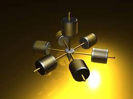
Neodymium, brass, nickel, stainless, copper. Variation of Lockheed Martin patent by Boyd Bushman. #5,929,732.
7"W x 7"H x 4"D
http://www.warriormatrix.com/about4003.html&sid=51cfaf396a72c42becd2bfefce3f5b03

This is the Beamer Patent Drawing
According to the patent, this configuration creates a beam of some kind, represented by the series of dotted line circles extending out from the device. The author claims it is magnetic energy, but my own magnetic field analysis, and experiments show the magnetic field, while enhanced in this direction, does not appear to extend out to five feet as is claimed in the patent. (the magnetic flux does not appear to go this far at any appreciable strength, but a subtle energy effect does!)

This is a plot of the magnetic field given off by a Beamer
The unusual properties of this beam, as described by the author, are very similar to the properties of a Primary Energy beam. And as the inert gases do exist as natural components of air, perhaps this beam he speaks of is a concentrated PE beam? (note in the next chapter a more powerful "Beamer" device is constructed, and it has a PE emanation all the time - and more so when you insert inert gas tubes into the "beam" area.)
He further claims that if you place a conductive coil (60) in the beam, and connected in series with a special unbalanced capacitor (65), and a voltmeter; that a voltage is produced which will vary if any object is in the beam, or any movement occurs in the beam. (yet to be tested)
Alternatively, if you place just the special capacitor in the beam (70),it will register a voltage if any movement occurs in the beam.
He further claims that if you place a coil over the unopposed magnet (80), and apply an ac current at various frequencies, you can modulate this beam, causing various effects at a distance.

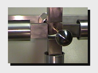
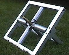
This is an experimental Beamer
I hope this will be interesting and of some use perhaps
Neil
https://www.youtube.com/watch?v=b2mmen7r92I
Replicating the Boyd Bushman Gravitational Experiment
by William Alek and Michael Ellegion
by William Alek and Michael Ellegion
"Could gravity be related to its cousin magnetism?" Boyd Bushman's experiment is performed by others with similar results :
(SNNS) Opposing magnets inside the rock cause it to fall slower.
(NSNS) Attracting magnets inside the rock cause it to fall faster.
US5929732
Apparatus and method for amplifying a magnetic beam
Apparatus and method for amplifying a magnetic beam
Inventor(s): BUSHMAN BOYD B
An apparatus and method for creating a magnetic beam wherein a focusing magnet assembly (45) is comprised of a first opposing magnet pair (20) and a second opposing magnet pair (30) disposed in a focusing plane, each magnet of the respective opposing magnet pairs having a like pole directed towards the geometric center of the focusing magnet assembly (45) to form an alignment path, two like magnetic beams extending from the alignment path on each side of the focusing magnet assembly (45), each beam being generally perpendicular to the focusing plane. A like pole of an unopposed magnet (10) can be directed down the alignment path from one side of the focusing magnet assembly (45) to produce a single magnetic beam extending generally perpendicular from the focusing magnet assembly opposite unopposed magnet (10). This beam is a magnetic monopole which emits pulses, levitates, degausses, stops electronics and separates materials.
TECHNICAL FIELD OF THE INVENTION
The present invention relates generally to the field of magnetic devices, and more particularly to focusing a magnetic field to increase the efficiency of a magnet.
BACKGROUND OF THE INVENTION
Magnets have a variety of commercial uses. For instance, magnets perform a variety of physical tasks by attracting ferric materials, and magnets also perform a variety of electrical tasks, such as creating an electric current in a generator or alternator or enhancing the performance of electromagnetic devices such as inductors. However, the creation of a strong magnetic field to perform these functions generally entails the use of a large permanent magnet or a powerful electromagnet. Such magnets are often physically large and heavy, and tend to produce wide magnetic fields which can interfere with equipment near the magnet. Thus, commercial devices that include magnets must be designed around the physical size of the magnet needed to produce a desired magnetic field and around the width of the magnetic field produced.
SUMMARY OF THE INVENTION
Therefore, a need has arisen for an apparatus and method for manipulating and focusing the magnetic field of a magnet to reduce the size and strength required for a given magnet to perform a function.
In accordance with the present invention, an apparatus and method is provided that substantially eliminates or reduces disadvantages and problems associated with previously used unfocused magnets. The present invention uses opposing magnetic pairs to direct a magnetic field along an alignment axis.
More specifically, the present invention focuses a magnetic beam along an alignment axis by providing a focusing magnet assembly having at least three opposing magnets spaced apart in a focusing plane, the space between the opposing magnets forming an alignment path, and by further providing an unopposed magnet generally directed along the alignment axis towards the alignment path. Each opposing magnet has a like pole facing across the alignment path. The alignment axis corresponds to the alignment path formed by the spacing between the focusing assembly of magnets. In one alternative embodiment, the unopposed magnet can be placed in the focusing plane to form opposing magnet pairs which direct a magnetic beam from the alignment path along the alignment axis from each side of the focusing assembly.
In one alternative embodiment, a coil of conducting material is disposed in the magnetic beam near the exit of the beam from the focusing magnet assembly. An unbalanced capacitor and a voltmeter connected in series with the coil allow the detection of movement through the magnetic beam by measuring variations in the AC voltage of the coil. Alternatively, AC voltage can be measured from a pin array disposed in the beam as a substitute for the coil and unbalanced capacitor. In yet another embodiment, electric power, such as an alternating current, can be passed through coils arranged around one or more of the magnets of the assembly to allow the generation of a magnetic pulse.
The focused magnetic beam or beams produced by the present invention provides important technical advantages by focusing a magnetic field. The focused field may perform functions using less total magnetic force than is generally used by an unfocused magnet. This allows for the use of smaller permanent magnets, or alternatively, electromagnets that use lower amounts of electric power. Thus, a commercial device built with magnets according to the present invention can be built smaller and with less of a need for power consumption than devices using standard magnets. For instance, the present invention can be used to more effectively separate ferric materials from non-ferric materials, and can more effectively induce propulsion or levitation in systems that use magnetic fields, such as electric motors or levitating trains that use opposing magnetic fields. The present invention can also interact with electromagnetic devices such as computers by stopping the operation of analog circuits from a distance, degaussing and otherwise interfering with digital circuits and memories, and emitting high powered electromagnetic pulses (EMP) at such circuits when induction coils are energized around the magnets with an alternating current. The present invention can also direct or transport electromagnetic charges through a distance.
BRIEF DESCRIPTION OF THE DRAWINGS
A more complete understanding of the present invention and advantages thereof may be acquired by referring to the following description taken in conjunction with the accompanying drawings in which like reference numbers indicate like features and wherein:
FIG. 1 depicts an assembly of five magnets to produce a magnetic beam;
FIG. 2 depicts a magnetic beam adapted to detect motion; and
FIG. 3 depicts an electronic coil disposed around an opposing magnet for producing a magnetic pulse beam.


DETAILED DESCRIPTION OF THE INVENTION
Preferred embodiments of the present invention are illustrated in the figures, like numerals being used to refer to like and corresponding parts of the various drawings.
Referring now to FIG. 1, one embodiment of the present invention is depicted creating a south magnetic beam 5. A single unopposed magnet 10 is aligned along an alignment axis 15 so that the south pole 11 of magnet 10 points substantially in the direction of the intended magnetic beam. The alignment axis 15 in FIG. 1 is labeled as the "X" axis. A first opposing magnet pair 20 is disposed along a first or "Y" axis 25 substantially perpendicular to the alignment axis 15. Opposing magnet pair 20 is comprised of two magnets, 21 and 23, substantially aligned along the "Y" axis 25 so that the south pole 22 of magnet 21 and the south pole 24 of magnet 23 face each other. Magnets 21 and 23 are arranged to have a space between them which coincides with the path of alignment axis 15.
A second opposing magnet pair 30 is disposed along a second or "Z" axis 35, which is substantially perpendicular to the alignment axis 15 and also substantially perpendicular to the "Y" axis 25, the first and second magnet pairs forming a focusing magnet assembly 40. Second opposing magnet pair 30 is comprised of two opposing magnets, 31 and 33, each substantially aligned along the "Z" axis 35 so that the south pole 32 of magnet 31 faces the south pole 34 of magnet 33. Magnets 31 and 33 are arranged with a space between them, the space coinciding with the path of the alignment axis 15. The spaces of first and second opposing magnet pairs 20 and 30 coincide to form an alignment path 45 through which the alignment axis 15 is disposed. The first axis 25 and second axis 35 intercept within alignment path 45 at the approximate geometric center of the magnet assembly to form a focusing plane.
In the embodiment depicted by FIG. 1, each magnet has approximately the same magnetic force, and each magnet is a niosyum magnet constructed in the form of a cylinder with a hole 50 down its center. Nonferric bolts 51 are inserted through each hole and intersect at the geographic center of the magnetic pairs, where the Nonferric bolts can be coupled to hold the magnets in place. In alternative embodiments, any other convenient means of coupling the magnets in place can be used, and alternative means of producing a magnetic force, such as electromagnets, can be used. In another embodiment, unopposed magnet 10 can be removed so that a magnetic beam extends along the alignment axis 15 from each side of the focusing plane.
The embodiment of FIG. 1 depicts a like pole of each magnet directed towards the geographic center of the focusing magnet assembly 40. In FIG. 1, the south pole of each magnet is depicted as directed at the alignment path 45 and at the geographic center of the focusing magnet assembly 40. In other embodiments, the north pole of each magnet can be directed at the geographic center. In either case, the coupling of like poles in a plane and the introduction of a like pole perpendicular to the plane acts to focus the magnetic fields of each magnet into a beam extending perpendicular from the focusing plane along the alignment axis 15 of the single unopposed magnet 10. Thus, an unopposed magnet that would ordinarily have a measurable magnetic field of four to six inches extending outward from a pole can have a beam extending five to seven feet outward from the pole. The focused magnetic beam 5 extends along the alignment axis 15 beyond the magnetic field that would occur if each magnetic field of the beam assembly were combined into a single magnetic field, such as would happen if each of the magnets were combined end-to-end. The direction and intensity of the beam can be altered by changing the alignment of the single opposing magnet 10, or by changing the position or strength of the magnets in the focusing magnet assembly relative to the focusing plane, or by changing the shape or configuration of individual magnets. Thus, for instance, the beam could be made to rotate around alignment axis 15 by sequentially altering the strength of each magnet in the focusing magnet assembly.
The increased magnetic field of the embodiment depicted in FIG. 1 can be demonstrated by its physical effects. For instance, an unopposed magnet 10 that can lift a ferric object at a distance of approximately one inch can lift the same ferric object through a distance of approximately six inches when coupled to a magnetic assembly comprised of two pairs of opposing magnets as is depicted in FIG. 1. The same assembly can cause cathode tube distortions at a distance of approximately two feet, can make electronic systems inoperable at a distance of approximately six inches, and can double the performance of an inductor at a distance of approximately eight inches.
In another example of the physical effects of an embodiment such as that depicted in FIG. 1, a VanDeGraaff generator with a spark potential of approximately three quarters of an inch from its bell can be placed between an assembly of north opposing magnets and an assembly of south opposing magnets, the north opposing magnets located eight inches from the bell, and the south opposing magnets located five feet from the bell, with the bell located one foot from its base. This configuration will produce a large spark from the VanDeGraaff to the south opposing magnets, indicating the potential for the present invention to perform electron transfer through a distance.
In alternative embodiments, various numbers of magnets or opposing magnet pairs can be arranged around the alignment axis 15 to focus the magnetic beam 5. For instance, three opposing magnets could be used instead of the four opposing magnets depicted in FIG. 1. Alternatively, a greater number of magnets or magnet pairs can be arranged offset to the focusing plane to alter the focus or strength of the magnetic beam 5. In yet another embodiment, a plurality of focusing magnet assemblies can be disposed along the alignment axis in a plurality of focusing planes.
Referring now to FIG. 2, two alternative embodiments of the present invention are depicted. First, a coil 60 comprised of a conducting material, such as copper, is disposed within a magnetic beam 5. An unbalanced capacitor 65 is coupled in series with the coil 60 and a voltmeter 66. Unbalanced capacitor 65 can be an electrical device such as the electrical device disclosed in U.S. patent application Ser. No. 08/144,814, by Boyd Bushman, abandoned, now issued as a continuation-in-part as U.S. Pat. No. 5,637,946, which is incorporated herein by reference. Voltmeter 66 is any conventional voltmeter capable of measuring an electric current, such as an alternating current. Movement, and even just the presence of objects, through the beam produces an AC voltage in coil 60 which can be detected by unbalanced capacitor 65 and measured by voltmeter 66.
Alternatively, a pin array 70 disposed in the magnetic beam 5 can also be used to measure disturbances, such as movement through the magnetic beam, which cause an AC voltage in pin array 70 that can be measured by voltmeter 66. Pin array 70 is any device such as the device disclosed in U.S. patent application Ser. No. 08/144,814, by Boyd Bushman, abandoned, now issued as a continuation-in-part as U.S. Pat. No. 5,637,946, which is incorporated herein by reference. Alternatively, any other means of measuring a disturbance through a magnetic field can be used.
Referring now to FIG. 3, a coil 80 comprised of a conducting material, such as copper, is depicted disposed around single unopposed magnet 10. An electric power source, such as an AC generator 85 supplies an alternating current to coil 80 at a variety of frequencies. The strength of the magnetic beam 5 varies according to the frequency of the alternating current through coil 80 due to the magnetic field created by coil 80. Thus, a magnetic pulse beam is generated according to the frequency of the current passing through coil 80. When the frequency of the AC current is high, such as ten to the fifteenth power hertz, the magnetic pulse emitted simulates the effect of a destructive electromagnetic pulse. In alternative embodiments, coils can be disposed around each magnet or around the magnet assembly as a whole to create a magnetic field and pulse according to the frequency of a current applied to the coil.
The present invention provides several technical advantages related to the application of a magnetic field. For instance, by focusing a magnetic field, the present invention allows for a decrease in the size of magnets used in commercial devices. Thus, in commercial applications such as where a magnet is used to increase the efficiency of an inductor, the present invention allows for greater miniaturization with smaller magnets than would be allowed with the magnetic field of an unfocused magnet. Where the present invention is used with electromagnets, such as for the lifting of ferric materials, a smaller electric power source can be used to create a lifting magnetic force.
Other Patents :
US6028434 -- 100% Test Computer Printed circuits emit ultraviolet frequencies which identify its correct or defective operation. Only 1% to 10% are now tested.
US5999652 -- THREAT WARNING - Detection of aircraft and missile plume.
US5384802 -- Laser Apparatus
US5982180
Metal detection system and process using a high voltage to produce a visible electrical discharge
Metal detection system and process using a high voltage to produce a visible electrical discharge
The apparatus includes an electrical circuit for producing a high voltage at a high frequency with very little current and an elongated and electrically insulated electrical conductive member coupled to the circuit for producing an electrical discharge when in close proximity to a metal object in the ground. The electrical circuit is capable of producing 50,000 volts and higher. In using the apparatus, the electrical conductive member may be moved to scan the ground over a metal object to obtain an image of the shape of the metal object.
US5420588
Wave Attenuation
Wave Attenuation
A radar cross-section reduction system utilizes a charging device for creating a high positive DC static potential on an object such as an aircraft. The charging system is mounted to the object so that this DC potential would be applied to the outer skin or surface of the object. The charging system includes Van de Graaf generators located in housings attached to the object. Each Van de Graaf generator has two pulleys about which a belt is rotated. One of the pulleys and the belt are nonconductors, while the other pulley is a conductor. This results in a buildup of positive charges at one end of the belt and negative charges at the other end. The negative charges are picked off and applied to a ground section. The positive charges are picked off and applied to a collector. The collector is in electrical continuity with the outer structure of the object. Negative dissipators attached to the ground section dissipate the excess negative charges during flight. Positive dissipators may be selectively switched into engagement with the skin to dissipate the positive charge on the skin prior to landing.
US5542247
Apparatus Powered Using Laser Supplied Energy
Apparatus Powered Using Laser Supplied Energy
A method and apparatus are providing for converting energy into thrust, and directing the thrust to move an object. The apparatus includes a chamber having air disposed therein, a pulsed laser for converting an energy source into light pulses, and a lens for receiving the light pulses and directing the light pulses toward a focal point within the chamber. Each light pulse converges in a region which is proximate to the focal point and causes molecules within the air which are at the region to disassociate. Disassociation of the molecules generates pressure waves which provide thrust for powering the object to move.
US5680135
Radiation Communication System
Radiation Communication System
An aircraft has an exhaust flame or plume which can be modulated to communicate. A sound emitter is mounted to the aircraft for emitting acoustic waves into the exhaust plume. An encoder will control the emitter at selected digital sequence to provide a digital message. The flame or plume will radiate at a frequency range of interest depending on the type of aircraft. The sound waves cause the frequencies to change from a continuous spectrum to a spectrum which has a much lower amplitude. A detector remotely located from the aircraft will detect radiation. It filters frequencies outside of the frequency range of interest. It will discriminate between the modulated pattern and the continuous pattern. This output provides the digital code that was encoded by the encoder. A decoder will decode the message for the recipient.
US5637946
Thermally Energized Electrical Power Source
Thermally Energized Electrical Power Source
An electrical device functions as a thermally energized DC power source. The device has a base plate of conductive metal. A number of electrode points protrude upward from the base plate, terminating in a sharp edge. A collection plate of conductive metal is positioned above the sharp upper edges of the electrode points. The gap between the electrode points and between the collection plate and the electrode points is electrically insulated. An electrical potential exists between the base plate and the upper collection plate while the device is at and above room temperature. The potential difference increases as the temperature increases.