Alexey CHEKURKOV
Graviflyer
Graviflyer
https://www.youtube.com/channel/UCzZxKT3BzBZOVVy8_YzP6Yw/videos
Alexey
Chekurkov
https://www.youtube.com/watch?v=48FEtLskKFY
Anti
Gravity Invention by Alexey Chekurkov
https://www.youtube.com/watch?v=Z-M55XP3D4A
Alex
Flying Craft
https://www.youtube.com/watch?v=pPLhMLWn-GI
Alexey
Chekurkov Lift Craft with Circuit Analysis
https://www.reddit.com/r/Physics_AWT/comments/997eoq/antigravity_experiments_of_alexey_chekurkov/
http://web.archive.org/web/20181015171628/http://www.clandestinedisclosure.com/alexey-device.html
THE
ALEXEY DEVICE -- OBSERVATIONS AND QUESTIONS ABOUT HIS
ELECTRICAL SCHEMATIC AND HOW IT MAY WORK
by
Walter M. Nowosad, Jr.
September 24, 2018 / October 15, 2018
September 24, 2018 / October 15, 2018
RUSSIAN TO ENGLISH TRANSLATION
Just prior to publishing this page, I received an e-mail from one of my YouTube viewers, who provided a text file containing the full Russian to English translation. It has already helped one of our engineers in his efforts to build The Alexey Device.
A friend off mine – Aidar Mukhametzhanov – is a full-time student and moving company business owner, who legally immigrated to the United States from Kazakhstan a few years ago. He was good enough to invest a few hours of his time on a weekend to help me understand what Alexey says in this video. He helped clarify the meaning of one component, which was confounding us; and, you'll read about it in the SOUND section of this page.
A CLEAR SCHEMATIC
My recreation of Alexey's Electrical schematics was interpreted from the video recording of his pencil drawing. I’ve omitted component values and their units-of-measure from the diagram; because, his labeling was either unclear and difficult to read, or altogether missing; and, I didn't want to be the authority.

MOTORS
They appear to be lightweight pancake motors, akin to computer cooling fans. The lower motor could be a bathroom ventilation fan.
CAPACITORS
Symbols for electrolytic capacitors appear in circuits that may, or should be, some flavor of AC. Unless my memory from electronics school fails me, these types of capacitors are intended for DC-only circuits. If it's pulsed DC may be another issue to consider. It was difficult to read the polarity for C2. If it’s on an AC circuit, then the wrong capacitor symbol was used.
RESISTORS
The few resistor values appearing in Alexey's schematic were relatively easy to read; however, not all resistors included a value or unit-of-measure – ? vs. K? vs. M?, etc. so, I've omitted the values.
BIPOLAR TRANSISTORS
The schematic contains six transistors. Two numbers appear near one transistor at the base of the Tesla Coil's L2. One is a Russian transistor part number (KT819) and the other number – 250843 – could either be read as 2508Hz or 250843. During the team's Skype call (notes to below), we came to a consensus it’s 250,843, which would roughly represent 250 KV or 250 KHz. Two more Russian transistor part numbers KT838 and KT 815 appear beneath the transformer I've labeled TR1. This website shows equivalent Western part numbers. I’ve provided links to transistor data sheets, below. I was unable to locate a Western equivalent for KT838 and discovered some of them are obsolete.
KT838; KT38A / UNKNOWN
KT815 / BD165
KT819 (Same as KT 818G, but with n-p-n structure) / BDY20, BDY23
VOLTAGE SOURCES
The voltage values scribbled on the left could be 24V and 12V – can’t say for sure. The flavor of waveform Alexey applies is not specified; however, given images appearing in his video, the Tesla Coil L1 may be receiving a square wave from a switching power supply.

Throughout the video and in the comments section, I see repeated references to the “Katcher”. My best guess is that the power supply and circuit feeding the Tesla Coil is the "Katcher". In fact, you'll find imprinted on the black box “Switching Power Supply”.

Alexey says, “And this lead is only powering high-voltage power supply”. His schematic indicates two sources of high voltage from two different power supplies. Perhaps the 12 V Starter Battery is feeding the two white boxes. See the white text against a green field, “Two Boxes for powering discs”. We are unable to see all sides of them to determine interconnections. What’s contained inside is unknown.
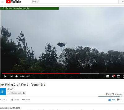
Later, the video shows Alexey disconnecting a white lead from the 12V / 44 Ah / 360 CCA starter-battery. The video whip-pans to reveal his device hanging in the sky for several seconds until everything discharges; and, it drops to the ground.
Source voltage values are difficlut to identify from Alexey’s pencil drawing. Have I incorrectly interpreted the top right source to be 24V? Should it be a 12 VDC starter battery? Is the starter battery we see the sole source of power for all three circuits?
1) Two motors & a piezoelectric ultrasonic sound generator sharing one circuit;
2) one Tesla coil primary feeding stepped-up high voltage via its secondary to the center fixed disc; and,
3) a “magnifying” circuit, which sources high voltage to the spinning plates.

What is the purpose of the circuit that contains transformer TR2? What is the function of the spark gap connected to TR2’s secondary, when its primary sees a 12 V DC signal from a Battery? My friend, who translated Alexey’s Russian, says this circuit powers a piezoelectric ultrasonic sound generator. When the sound interacts with the "special metal" (textured metal), you have levitation. The sound of a beetle’s beating wings interacts with the rough under-texture of its wing covers, which levitates the bug; so, the special metal – rough, textured, and bumpy – represents the beetle's rough under-surface, and the ultrasonic sound generator represents the beetle's vibrating wings. This is Alexey's nod to Viktor Grebennikov. Alexey doesn’t say what kind of metal it is or where it came from.
The ultrasonic sound generator is most likely physically positioned above the top motor and hidden under what appears to be a plastic dome, which could be a reflector scavenged from a large flashlight.
Could the dome we see on top be an inverted ultrasonic piezo speaker? I searched the Internet and found several; but, none of them resembled Alexey’s dome. We simply don’t know what’s underneath.
Could the Alexey device operate on sound alone? If so, could it operate in a vacuum? Not likely. What else could be used in place of sound - perhaps UV light, as suggested by William R. Lyne in his book, Pentagon Aliens, 3rd Edition? Note the external arching waves (left), analogous to sound waves – are these U.V. light resonators?
According to my Russian-English interpreter friend, Alexey says the device's voltages, frequencies, and ultrasonic sound must be in resonance.

When Alexey says he uses special metal, the metal is considered special because it’s textured.
One of our engineers recommended William R. Lyne’s book, Pentagon Aliens, 3rd Edition – and I can’t put it down. In it, he mentions quilted aluminum, which apparently was the crisscross ridge patterns of early stealth technology developed by the Germans during for their WWII U-boats, and adapted to the saucers. Friends of the author described seeing this pattern on UFOs. This brought Alexey’s mysterious metal to mind. A few seconds on Google; and, voilà! I find rigidized metal: Some suppliers call it Stucco metal.
I've overlaid a closeup image of the Device's special metal with Sample 1SLG. They look similar. According to this website, this texture is available in stainless steel and other metals.

The contacts (a strip of copper) provide a conductive path to carry a single polarity high-voltage pulsed charge to the spinning discs (positive on the top disc; and negative on the bottom disc).
How much voltage should the brushes be feeding the upper and lower rotating discs? According to my friend who translated Russian to English, the circuit following TR1's secondary “magnifies”.

Alexey’s drawing shows magnets mounted to one disk only; but, the device has magnets mounted to both discs. My drawing shows this. I assume north poles face each other. The functional purpose of the magnets are unknown - perhaps to channel the electric and magnetic fields into a spinning vortex?
POLARITIES - ELECTRIC CHARGE AND MAGNETIC POLES
While he admits he may not be using the right words in his explanation, Alexey rationalized the lower spinning disc should be negatively charged ~ to Earth. He continues by describing vortex fields spinning upward and downward from the rotating disks, which excludes it from Earth’s gravity; but, he stops short of describing the magnets' orientation.
HIGH VOLTAGE CHARGES
The middle stationary plate – charged by the Tesla coil – may act as an electric barrier to separate fields created by the high-voltage charged upper and lower rotating plates. One of our team members speculates its purpose may be to prevent the opposing polarities and fields from mixing and being neutralized. Alexey says everything must be in resonance – all three charged plates and the ultrasonic sound or vibration.
TWO DEVICES
Alexey features at least two devices on his YouTube channel. The one pictured here is not the same used in his indoor and outdoor video demonstrations. It is smaller in diameter, lighter weight; and, the discs are not made from a “special metal”. According to my translator, they’re CDROM discs!


With a copper contact in direct contact with the upper and lower rotating CDROM discs. We speculated the foil aluminum encased in the layers of polycarbonate may interact with the high voltage charge.
Since the copper brush is not in direct contact with a conductive plate, assuming the disc is not coated or sprayed with conductive materials and the only conductor present would be sandwiched between 1.2 mm of polycarbonate plastic (an insulator), if the goal is to apply a high voltage charge to the extremely thin layer of embedded aluminum, would breakdown voltage of 1.2 mm of polycarbonate material need to be taken into consideration prior to testing? How will the aluminum react to the pulsed charge? Will it heat up, expand, and cause the disc to come apart?
The upper rotating disc appears to be transparent from the high camera angle. If you’ve ever purchased sleeves of CDs or DVDs, you’ll know they ship with a clear plastic packaging insert at the top and bottom of the sleeve, which does not contain aluminum. Is that what Alexey is using here? If so, how will the rotating polycarbonate plastic discs receive a high voltage charge?
WIRING AND ELECTRICAL ISOLATION
A set of black and white wires and connection blocks are on top. The piezoelectric ultrasound device is absent. These four wires could be feeding power to both motors and the Piezoelectric Ultrasonic Sound Generator. Note the black triangles bolted to the lower stationary plate. Could these be insulators electrically restricting the high voltage charge to the center stationary disc?
WHAT'S NEXT?
Alexey says his next video will show how he tunes the circuits. As mentioned in an other video, it takes Alexey thirty to sixty minutes to tune the device.
During my Russian to English translation session I also got this: Too much high-voltage can prevent levitation. Who knows what other variables factor into the equation?
TEAM SKYPE CALL: September 15, 2018
During our call, we had another long-time pod member join us; and, we stepped through Alexey’s circuit and how we think it’s designed to. We discussed wave forms, such as a pulsed half-wave riding on an offset DC signal – positive at the upper and negative at the lower. The waveform could be square, or other. It could be in phase, or a number of degrees out of phase. We simply don’t know.
The signals at all three plates receive some flavor of pulsed DC.

Power source values are in question.
We pondered how Alexey’s circuit, as drawn, would be tuned for resonance or adjusted to ascend and descend.
Based on his circuit, it appears voltage and current values are the only adjustable variables. VR1 would vary current. My transistor knowledge is a little fuzzy; but, as I recall, depending on how the transistor is biased, changes in current and/or voltage affects frequency – the relationship may be inversely proportionate – as current increases, frequency decreases; and as current decreases, frequency increases. The amplitude of the signal varies with adjustments, as well; not to mention, the transistors would have to be capable of accommodating certain voltages, current, frequencies, etc. Again, I’m rusty on this stuff.
We pondered, what’s missing? Is Alexey hiding something? Is he concealing other control knobs or circuits? It was suggested as workaround to his circuitry: Rather than constructing your own Tesla coils, buy one off-the-shelf. For your High Voltage source leading to the rotating plates, it was suggested a neon sign transformer and a Variac – to enable tuning – could be used.
We attempted to identify electrical components appearing in one of Alexey’s previous videos. As shown here, there were four boxes – a black-colored metal box referred to as a “Katcher” (switching power supply), which apparently drives the Tesla coil; a white thing sporting a large dial (a dimmer / pot); a white and blue plastic thing; and a “throwback” (I think that's what it's called) from a television. How Alexey interconnected them to his device is unclear.
If you'd like to send me something:
WALTER NOWOSAD
PO BOX 5450
OCEANSIDE, CA 92052-5450
https://www.warp-drive-physics.com/construction-blog/antigravity-demonstration-using-counter-rotating-magnet-electrostatic-fields-from-russia
Antigravity Demonstration Using Counter-Rotating Magnet-Electrostatic Fields From Russia
https://overunity.com/18000/russian-alexey-chekurkov-magnet-high-voltage-antigravity-spinner/
Re:
RUSSIAN Alexey Chekurkov MAGNET HIGH VOLTAGE ANTIGRAVITY
spinner
November 23, 2018,
10:54:41 AM »Zoltan has published this in 2003 on electro-statics and now it's in a pdf document.. Alexi has all four components in his lifter and electrostatics is just one aspect here to make this lifter work..
Inconsistencies
in EM Theory - the Kelvin Polarization Force Density
Contradiction
by Zoltan Losonc
by Zoltan Losonc
Abstract
Calculations of resultant electrostatic force on a charged spherical or cylindrical capacitor with two sectors of different dielectrics, based on the classical formulas of electrostatic pressure, Kelvin polarization force density, and Maxwell stress tensor predict a reactionless force that violates Newton's 3rd law. Measurements didn't confirm the existence of such a reactionless thrust, thus there is an apparent inconsistency in the classical EM theory that leads to wrong results.[/font]
https://feprinciples.files.wordpress.com/2018/10/dielectrophoretic_force_anomaly_1-thruster_v1-2.pdf
The practical concept of reaction-less force and Newton’s 3rd law
Before starting the description we should clarify briefly the issue, what does the violation of Newton’s 3rd law mean, and define the concept of reaction-less force. According to our everyday experiences, forces are exerted upon a body either by physical matter through direct mechanical contact, or by force fields that are originating also from physical matter. Thus the force-field acts as a mediator medium between the two bodies made of physical matter and it develops an action and reaction in distance, but the forces seem to be the same as if the bodies would act upon each other through direct mechanical contact.
Newton’s 3rd law declares that if a physical body acts upon a second physical body with force a F then the second body will also act upon the first body with a force of same magnitude but opposite direction –F. That means, if there is an active force tending to accelerate a body then there must also exist another reaction force of same magnitude and opposite direction acting on a second body, and there cannot exist an active force without a reaction force.
If there would be such force then we could call it a reaction-less force, since it does not require any reaction force, or the presence of a second body (to react) in order to be active and accelerate a physical body. According to this interpretation if we measure a unidirectional electrostatic force (developed by the E-field) upon a thruster, we can call it reaction-less since it does not develop any reaction force upon physical matter and it does not require the existence of a second physical body in order to be active and be able to accelerate the thruster. This active force is originating from the electric force field and thus we might expect that consequently the reaction force should be transferred to the physical matter that creates this field (to electric charges, and from them to the atoms of a body); the law of action-reaction between physical bodies should still remain valid. However, in the case of E-field thrusters the sources of the accelerating E-field are the same charges that are present on the surface of the electrodes and the reaction force would act on these charges counteracting the active accelerating force. Thus no resultant thrust would exist on a thruster without the presence of external force fields and physical bodies. If we still prove that a resultant unidirectional thrust can exist upon a thruster that does not originates from external medium then it is justified to call it reaction-less since from a physical and practical point of view the reaction force does not manifest in the perceived rough physical dimension.
The force fields are special manifestations, energetic states of the background ether, and they are part of the ‘ether sea’ in which all matter flows. Thus they can lean upon this subtle fluid substance that represents a reaction background to interact with physical matter. Now we could say that we have found the reaction background and the law of action-reaction is still valid, since the force-field (i.e. the ether) bears the reaction force that should have the same magnitude as the action force upon the thruster. However, the substance of the reaction background (the ether) belongs to a more subtle dimension, and it is not a rough physical matter that would have the same characteristics as the well known physical matter. Therefore from practical point of view we can still call the discussed thrust ‘reaction-less’ within the rough physical dimension (or frame of reference) to differentiate it from the usual forces that always invoke a reaction force upon physical bodies.
http://energythic.com/view.php?node=208
http://Warp-Drive-Physics.com
Antigravity
Demonstration Using Counter-Rotating Magnet-Electrostatic
Fields From Russia
Special thanks to Walter Nowosad for sharing this.


 ii
ii


"Special Metal" is unknown. It looks like hammered tin, or an aluminum/bismuth alloy, hand-forged. It looks coated; plated, and easy to machine. It is known that the disks may become magnetized, meaning it is a ferrous alloy. It won't work when the disks are magnetized, probably causing a problem with spinning, or otherwise electrical disruption due to homopolar motor effects back-feeding into the external high voltage power supply.
He does have a lot of that metal on hand, however. He has made other apparatus from that metal, as per links below. It resembles an iron / tin allow for corrugated roofs with perhaps, a galvanized zinc plating.
It would most probably be a standard type of easily-acquirable metal.
Also note the power supply in the video below, using a Tesla resonance transformer. His standard power supplies however are using "positive energy," rather; whereas these metal disks are essentially rotating air capacitors. Being able to conduct magneto-electrostatic fields and usage of the Tesla resonance transformer denote that they are charged as a field at high volts, using non-standard electromagnetic (positive) energy; and the electromagnetic energy from the transformers would be going toward powering the motors that spin the disks, not using homopolar motor technology.
Note the blending of the energies of magneto-electrostatic and electromagnetic in high volts.
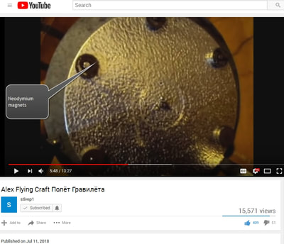
Furthermore, he uses neodymium magnets in the positions of the utrons near the outsides of his lower disk. The magnetic field near the outside while spinning them, denotes the electromagnetic collapse of magnetism toward the center -- in that field geometry.
This begs the question of the utrons being magnetic, whereas the outer electromagnets of the X1 collapse somehow in timing with the passing utrons, and a coil around the utrons could be built to handle that collapsed energy in polarity opposite of the utron-magnet, to deaden or cancel the utron's magnetic field in order to pass through the electromagnetic gate.
Aside from that complex structure, a homopolar motor design with electrostatic rotating disks may actually be able to handle rotating magnets spinning in the opposite direction of one of two counter-rotating field disks; it seems that the rotating magnetic fields are only traveling in one direction.
It's easy to see the device comprised of two capacitor sets, one on top (with lower rotating disk), and one on the bottom, with lower rotating disk with magnets. He is NOT using homopolar motor technology, and he's using an external Tesla coil power supply, instead of integrating that into his design, although it is using a conductive hollow "hat" similar to a Tesla tower. Also note the static disk, rather the disk that is not moving, with the frame "landing legs" sticking through it.
Note the bottom rotating disk is wider than the upper rotating disk, keeping to principles of the magnet and dielectric layers, using a wider magnet on bottom and on upper magnet, in less width, in adherence with the Townsend Brown in a vacuum test shown on the pdf file on the Construction page in the Townsend Brown section.
Part of it is powered through a Tesla resonance coil.
Here are some of Alexey's comments:
"A new lightening disk was made and a video was shot. But someone influential complained and yutub blocked the roller. But one user managed to download and reapply but again called feykovy flight. He decided that if the terminal with akamulyatora removed means fake. But I explained that from time to time you need to remove the power from the TDX to prevent the magnetization of the disks and prevent the subsidence of the parameters. If you have not seen the movie, I'll throw the link."
"This corrugated aluminum with an anodized coating structure similar to the beetle fenders. So successfully coincided."
Guess I need to mention Alexey mentioned in a comment on one of his bug wing videos what the material is -- the anodized corrugated aluminum. I spent hours translating Russian into English and searching.
This represents the first successful testing of the rotating and counter-rotating charge antigravity craft, able to lift a considerable amount of weight, and when applied in an air-tight resonance cavity hull may also work in a vacuum.
So now we know that the rotating and counter-rotating charge principle of physics DOES WORK.
PART II
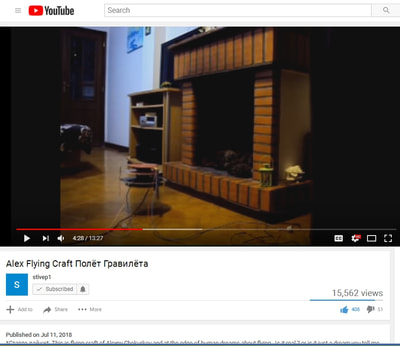
I want to take some still-shots of the videos, and notes, to have a photo reference, just in case, because Alexey mentioned that his prior videos were removed from YouTube in order to suppress the technology.
He uses modified high voltage power supply from switching power supply for his original test. The first disk is powered up using a standard motor, plugged into a wall socket (power strip) which gets it to spin, as is the second disk. The disks are mounted to stationary frame (stationary disk), which the two motors are bolted to. The disks are arranged as capacitors, so the presence of unmoving disks in the engine will not cause it not to work.
After the two disks (the one on the very bottom, and the second one from the top) are spinning in opposite directions, most definitely. You can adjust your video settings for high quality to see better. The next step is to connect the high voltage power supply (after all, as I've said before, all forms of electrogravity use high voltage). In the OTC-X1, that is achieved through high volt flyback from the electromagnets.
Okay. The high voltage is plugged into the stationary disks by the looks of things, and the rotating disks picks up one polarity of the dielectric charges, but both stationary disks are on top of the rotating disks, so the orientation typically used is positive up and negative on bottom. If using positive on the bottom, it would be repulsive to the Earth surface charge, and not achieve significant height, in my opinion.
The orientation of negative on bottom and positive on top effectively means that the co-counter-rotating disks are spinning positive against negative, looking at this in the form of capacitor geometry. His high voltage source is the typical high voltage transformer from a CRT tube and improvised voltage multiplier (positive energy high volts, just like most people do with their electrostatic lifters). You can hear the zzzzzaping when he plugs in the voltage multiplier.
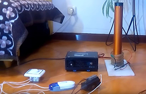
High voltage supply is the box in the middle photo. Multiplier is the hand-held device on the floor in the right photo.
He says the high voltage performs the "magnetization of sectors." It's in Russian, but there is an English translation.
Voltage and speed (inertial frequency).
The bottom left is levitating. Bottom middle is side profile. Bottom right is the bottom of the engine, and those are the 6 neodymium magnets.
PART III
Okay so here is the successful test model version 2.
The mess on the left is the power supply. Tesla resonance transformer, and immediately to its right is the power supply for it. The box on the far right is the independent power supply for the transformer block, and the little white box on top of the big white box is the high volt power supply. It's all connected to the 12 volt battery. I'm recording this for posterity, just in case.
Alexey continues to explain that a conflict of sequences steps caused his previous model to fall down, and he has to do a lot of fancy adjustments to get the craft to go up in the air, and sometimes it may take 30 minutes to balance everything correctly. Basically he explains that his power supply system has to be charged up in a certain order, probably due to resonance, like how a capacitor has to be charged first in a basic LC circuit (see the article below), and then when resonance starts to break down, he needs to provide an input to the capacitors, but it ends up going to the wrong place (the transformer instead of the capacitors), and his high voltage signal starts to degrade.
I don't want to speculate here too much about his power system, though. Not yet.
The second device, his working prototype is impressive, and obviously upgraded from the first, yet still having the same overall characteristics, and using better field geometry.
We know now that he is using corrugated aluminum with an anodized coating, which was the same material he used for the CSE beetle (sound resonance cavity) experiments, from the Russian etymologist years ago who discovered that effect. The piece he is touching is the upper rotating disk. This is awesome! It's like a TR-3B engine (1 of 3 on the triangular hull's tips). Just think how this style can be adopted to use a homopolar motor design instead of dipole standard electric motors.
Here below is a better view of the whole top. The special field is theorized in different ways. One theory is a positive and negative electrical mass cancellation. Otherwise it's not very well known how it works to be honest. If you consider electromagnetic spin reverses on either side, up and down, left and right within orientation to electric fields relative to a plane of gravity, then the spin one way and spin the other way seems to cancel gravity, along the middle and much wider disk plane.
Magnets are involved, however. In fact, the article below this one showing the little diagram of the outer electromagnets in homopolar motor configuration spinning two disks in opposite directions is similar but I REALLY LOVE the concept of the centralized wider disk in Alexey's application. Similar to magneto-electrostatic, or just static electricity with the two counter-rotating disks creating electrostatic friction on the central wide disk. The two rotating disks appear similar in size.
If you notice also where the high volt top disk is, it is connected via frame to the central disk, but later on it shows Alexey touching the legs of the device during levitation, and touching the bottom middle.
He uses three wires: one high volt from the Tesla resonance transformer, and two wires from the rotating disks. I would say he is using a homopolar motor design in this version, due to only two wires to handle the rotating disks, and the third as the high volt magneto-electrostatic feed.