Patrick
PEEBLES
FanWing
FanWing


Could
FanWing go from LSA to heavy lifter?
By
Robert Coppinger
By
Robert Coppinger
FanWing image by Adrian Mann, © FanWing Ltd 2011
Very little of Patrick Peebles’ invention could be called conventional. The FanWing looks like someone has put the blades of a combine harvester behind a helicopter cockpit and forgotten about the rest of the fuselage. That combine harvester, the FanWing propulsion system, is a fan in a wing, making it a thick wing that provides lift and thrust.
It has a fixed wing but can autorotate like a helicopter. It has two engines, but they are at either end of the wing. It has two booms instead of one. Its inventor is American, but this invention has been developed in England and Italy. Its lift efficiency is so good that university studies in the United Kingdom have concluded 100 horsepower could lift 5,732 pounds.
This has been proven through wind-tunnel testing at Imperial College London, work carried out at Kingston University London, and scale-model flight tests funded by the development agency of London, England, and the U.K. government’s equivalent of the U.S. federal department of commerce. The aircraft’s efficiency is achieved because the air is accelerated twice: First the rotor accelerates it as the blades rise from the front bottom to the top and then again as the rotor moves back toward the wing’s trailing edge.
The FanWing has two engines for redundancy. One engine can keep the aircraft in the air and give it the power to climb. But if the worst happens pilots can autorotate down with a glide ratio of about 3:1. Peebles likes to say the FanWing is similar to a helicopter but with a much simpler drive train.
The high lift efficiency, according to Peebles, gives it good stall resistance, stability in turbulence, short takeoff and landing capability, and good fuel economy. The wing’s twin-tail outboard stabiliser configuration avoids a strong downwash behind the wing and recovers energy from the wingtip vortex upwash. This is not just theory: Since June a 5.57-foot wingspan remote-controlled prototype with a takeoff distance of 12 feet and takeoff weight of 20.9 pounds has been flying at up to 40.5 knots for 10 minutes or more to a few hundred feet altitude. Based on this prototype’s performance Peebles predicts a full-sized 22,000-pound FanWing aircraft would have a cruise speed of around 100 knots.
FanWing in flight - image copyright FanWing Ltd 2011A scale-model remote-control FanWing has been flying in Italy. © FanWing Ltd. 2011
Peebles doesn’t have the funds to develop such a large aircraft that could be an airliner or cargo carrier; instead he is aiming at a two-seat light sport class technology demonstrator that he wants to fly publicly for the first time at the Experimental Aircraft Association’s (EAA) AirVenture in Oshkosh, Wis., in 2013.
Alameda, Calif.-based marine and aerospace components manufacturer Photon Composites Inc. will build the FanWing technology prototype. Photon’s owner, British-born engineer Richard Jenkins, has supported new transport technologies before. He was a director of the British environmental transportation project Greenbird, a wind-powered vehicle that achieved 126.2 mph on Ivanpah Dry Lake in California in March 2009.
The total length of the prototype demonstrator, including the wing’s tails, will be 22.9 feet, and its total width with its outboard stabilisers will be 45.9 feet, including 32.8 feet of wingspan. Preliminary studies indicate that the two-seater will have an empty weight of 661.3 pounds and two 50-hp two-cycle engines driving either side of the FanWing rotor. The cruise speed is expected to be about 60 knots, with a top speed of 80 knots. The rotor speed will be 1,500 rpm, and flight control will come from the rotor rpm and the tail surfaces. Its takeoff distance is expected to be 49.2 feet.
Still looking for investors so he can build the demonstrator and then get the necessary FAA and EAA approvals for the 2013 flight, Peebles expects to display a static model of the technology demonstrator at next year’s Oshkosh show.
He said the light sport aircraft “is a major new phase for the company. This interim technology demonstrator will on one side take us forward on the [research and development] R&D and on the other side offers a neat little STOL [short takeoff and landing] light aircraft.”
International interest in the FanWing has seen the Aerodynamics Research Institute of Chinese aircraft maker AviChina investigate the concept and publish a technical paper on it. To protect the intellectual property Peebles now has patents in 10 countries including the United States, China, Australia, and various European countries.
Over the last 10 years of development Peebles has counted about 100 investors as his FanWing supporters, and he is in talks with potential new partners. The twin-tail outboard stabilisers, Peebles believes, have made the FanWing more commercially attractive because the new configuration has increased the forward speed to the equivalent of a civilian helicopter. Previous studies of other FanWing configurations had predicted a slow cruise speed.
FanWing - Image copyright FanWing Ltd 2011The FanWing looks like someone has put the blades of a combine harvester behind a helicopter cockpit and forgotten about the rest of the fuselage. Image by Adrian Mann, © FanWing Ltd. 2011
“George Seyfang originally suggested the twin tail, then got involved in the tests and has basically turned things round for us,” said Peebles. Seyfang, a retired BAE Systems principal future concept engineer, joined the FanWing team two years ago. Seyfang spent his career working on aerodynamics at BAE’s Warton Aerodrome site in northern England. BAE is the U.K. aerospace manufacturer whose antecedent companies built the Supermarine Spitfire, Hawker Siddeley Harrier GR7 “jump-jet” and the British Aircraft Corp. Concorde. All of these aircraft are classic designs, and if Peebles and Seyfang can succeed, the FanWing may join them in the aviation hall of fame.
Robert Coppinger is an aviation journalist based in London, England.

FanWing
FanWing or fan wing is a concept for a type of aircraft. It is distinct from existing types of aircraft like airplanes and helicopters in using a fixed wing with a forced airflow produced by cylindrical fan(s) mounted at the leading edge of the wing.
Its makers claim it is the first horizontal-rotored integral lift and propulsion wing in history to sustain flight.
FanWing is also the name of the company created to develop the concept.
The fan-wing is a radical solution for the problem of how to get the maximal airflow through both the propulsion and lifting surfaces. A cylindrical radial turbine (resembling a cylinder mower) is embedded in the wing with its axis parallel to the wing and leaving about 2/3 of the diameter exposed above the top side of the wing's length just after the leading edge. This increases the velocity of the airflow across the wing's upper surface beyond that of the forward motion of the aircraft. Consequently the wing has lift at slow speeds where a normal wing would stall.
Practical trials with various remote-controlled models have proven that the concept provides a vehicle capable of controlled flight. There are however some significant differences compared to normal fixed-wing flying:
* The throttle directly affects the pitch which means increased throttle can slow the plane down much in the same manner a helicopter flares, and if carelessly applied can force a complete mid-air stop.
* Glide-ratio in case of power-failure is rather low (about 1:3) but if the power-line is disengaged, the fan-wing is fully capable of doing an auto-rotational landing.
FanWing, the developing company, also have high hopes of the configuration being more silent, having V/STOL capabilities, stability in cross-winds combined with low to zero risk of stalls and a very low build/maintenance costs. These claims have yet to be verified with full-sized fan-wings though.
History
Patrick Peebles developed the FanWing concept in 1997. He formed the FanWing Company and applied for patents on his idea in several countries where aircraft are manufactured. In July 2005 the company advertised that the first FanWing aircraft was in development in the United Kingdom. They advertised that the concept has undergone wind tunnel tests and powered model flights, and that the UK government was contributing to its further development.
Prototype
In May 2007 the developers announced that a version built for low speed STOL urban surveillance as a drone was at the prototype stage and claimed the following performance. [1]
* Airborne after a ground roll of just 1 m (3 ft).
* Wing-span 2.4 m (7.8 ft) UAV,
* Made from composite materials,
* Dry weight of 5.5 kg (12.1 lb),
* Maximum take-off weight 12 kg,
* Payload capability 2 kg,
* Powered by a 1.2 kW electric motor,
* Flight speed 15.5kt (29 km/h),
* Endurance, (development goal) 80min.
Notes
1. ^ FanWing UAV gets airborne after ground roll of only 1m Rob Coppinger, Flight International 01/05/07, Accessed August 2007.
References
* "More-powerful Fanwing set to fly" Flight International Magazine, November 2004
* "2004 Year In Ideas: The FanWing" The New York Times Magazine, 12 December 2004
* "A Leonardo da Vinci for the twenty-first century" The Independent, 6 September 2004
* "It looks like a lawnmower, was designed in a kitchen - but it could revolutionise aviation" The Independent, 11 November 2002
* Slashdot: Fanwing Planes?
US2011101173
Aircraft with Aerodynamic Lift Generating Device
Aircraft with Aerodynamic Lift Generating Device
EC: B64C23/02 // B64C39/00C1
IPC: B64C23/02 // B64C23/06 // B64C29/00
2011-05-05
Abstract -- An aircraft (1) comprising: a fuselage (2), opposing wings (3, 4) either side of the fuselage (2), each wing (3, 4) supports at least one tangential flow rotor (5) and has a rotational axis. At least one tail section (3A) is disposed on each wing (3, 4) for forming a wing trailing edge. The tail sections (3A) are moveable about the, or each, rotor axis (X) relative to the fuselage (2) so as to provide, in use of said aircraft (1), variable thrust forces, whereby in use, movement of the or each tail section (3A) controls the flight of the aircraft (1). Lift is generated by way of a shroud (12) which forms an extension to the tail section (3A) curved surface or cowl to jointly cover a proportion of the circumference of the rotor. Ideally the shroud (12) and tail section curved surfaces create a vortex chamber generally within the rotor. An alternative embodiment includes a vertical axis fan (6) is provided on the fuselage (2) to adjust aircraft "pitch".
BACKGROUND
[0001] The present invention relates to an aircraft with an aerodynamic lift generating device.
PRIOR ART
[0002] It is known to use lift generating devices for powering aircraft. Such devices are disclosed in my prior Patents EP-B-0 918 686 and U.S. Pat. No. 6,527,229, the contents of which are incorporated herein by reference. Such lift generating devices provide an alternative means of propulsion to conventional propellers and the like, and lead to improved efficiencies.
[0003] European Patent EP-B-0 918 686 describes a lifting member that may be employed in either a liquid (hydrofoil) or gas (aerofoil). A wing like member is disclosed in which a spanwise extending rotor is housed. The rotor is positioned adjacent the leading edge and defines a fluid intake region. As the rotor rotates about a drive axis, fluid is drawn in and forced across the hydrofoil or aerofoil so as to create lift.
[0004] The present invention seeks to provide an aircraft with an improved lift generating device in which the thrust direction can be altered. Therefore the invention finds particular application in aircraft referred to as vertical take-off and landing (VTOL) or aircraft referred to as short take-off and landing (STOL) as the improvement provides both vertical thrust for vertical take off and forward thrust for propulsion.
SUMMARY OF THE INVENTION
[0005] According to the present invention there is provided an aircraft comprising: a fuselage, opposing wings either side of the fuselage, each wing supporting at least one tangential flow rotor having a rotational axis, and at least one tail section for each wing forming a wing trailing edge, said tail section being moveable about the or each rotor axis relative to the fuselage so as to provide, in use of said aircraft, variable thrust vectors, whereby in use, movement of the or each tail section is used to control flight of the aircraft.
[0006] Preferably movement of the or each tail section is vectored by rotating the wing casing whereby the lift component increases while the thrust is reduced. This allows the aircraft forward flight as well as vertical take off and facilitates vertical landing.
[0007] Preferably the or each tail section includes a curved surface which covers a proportion of the circumference of the rotor. The curved surface or cowl may have a radius of curvature substantially equal to the radius of curvature of the rotor. The curved surface of the tail section may be offset relative to the curved circumference of the rotor.
[0008] Preferably the or each tail section includes a shroud extending therefrom, said shroud including a curved surface or cowl which covers a proportion of the circumference of the rotor.
[0009] Advantageously the shroud forms an extension to the tail section curved surface to jointly cover a proportion of the circumference of the rotor. Preferably the shroud and tail section curved surfaces create a vortex chamber generally within the rotor.
[0010] In one preferred embodiment the shroud is fixed to the tail section. Preferably the tail section and shroud are moveable about the or each rotor axis relative to the fuselage.
[0011] In another particularly preferred embodiment the shroud is connected to a fixed point of a wing, and is adapted to slide over a portion of the tail section whereby the proportion of the circumference of the rotor covered by the shroud curved surface or cowl and tail section curved surface or cowl varies as said tail section moves about the, or each, rotor axis.
[0012] The radius of curvature of the shroud curved surface or cowl changes as said tail section moves about the or each rotor axis. The radius of curvature of the shroud curved surface or cowl may be non-uniform along its length.
[0013] Preferably a wing leading edge is provided for each wing in the form of an air input duct to allow passage of air to said rotor. Preferably the duct is variable in size to control the amount of air passing therethrough whereby to control "roll" of the aircraft.
[0014] Preferably a vertical axis fan is provided at or near the rear of the fuselage to control the aircraft "pitch".
[0015] An embodiment of the invention will now be described with reference to the drawings in which:
BRIEF DESCRIPTION OF THE FIGURES
[0016] FIG. 1 shows a schematic perspective view of an aircraft in accordance with one aspect of the invention;

[0017] FIGS. 2A to 2C shows a schematic cross section view of a first embodiment of tail section and shroud; and

[0018] FIGS. 3A to 3C shows a schematic cross section view of a second embodiment of tail section and shroud, along with an input duct.

DETAILED DESCRIPTION OF PREFERRED EMBODIMENTS OF THE INVENTION
[0019] Referring to FIG. 1 there is shown an aircraft 1. Aircraft 1 has a fuselage 2, and opposing wings or aerofoils 3, 4 either side of the fuselage 2. Each wing 3, 4 supports a tangential flow rotor 5 having a rotational axis "X". The tangential flow rotor is housed within a rotor cavity.
[0020] Wing 3 has a tail section 3A forming a wing trailing edge. Tail section 3A is moveable about the rotor axis "X" relative to the fuselage 2. Similarly wing 4 has a tail section 4A forming a wing trailing edge. Tail sections 3A, 4A are moveable about the rotor axis "X" relative to the fuselage 1, thereby providing, in use of the aircraft, variable thrust vectors to create aircraft lift and forward movement as more fully described below.
[0021] In use of aircraft 1, movement of each tail section is used, inter alia, to control flight of the vehicle, especially to allow the aircraft forward flight as well as vertical take off.
[0022] Movement of the tail section in addition to providing lift can be used to control "roll" of the aircraft.
[0023] A vertical axis fan 6 is provided on the fuselage 2 to adjust aircraft "pitch". Rear tail wings 8A, 8B and rudder 9 may also be provided. In this sense it is appreciated that in a second aspect of the invention there is provided an aircraft comprising: a fuselage, opposing wings either side of the fuselage, each wing supporting at least one tangential flow rotor having a rotational axis, and at least one tail section for each wing forming a wing trailing edge, said tail section being moveable about the or each rotor axis relative to the fuselage so as to provide, in use of said aircraft, variable thrust vectors, whereby in use, movement of the or each tail section being used controls flight of the aircraft and a vertical axis fan located in the tail section and adapted to provide pitch control.
[0024] A motor or engine 7 is provided to rotate each flow rotor 5. Alternatively a magnetic field may be established so that on passing an electric current through the rotor, the rotor rotates. Alternatively an electric or magnetic field can be established by inductive coupling. Other drive systems include a turbo prop engine, jet engine or conventional piston driven engine.
[0025] Referring now to FIGS. 2A to 2C there is shown a cross section view of various positions of the tail section of a first embodiment. In FIGS. 2A to 2C, a tail section 10 (which may be used as the tail section 3A or 4A in FIG. 1) includes a curved surface or cowl 11 which covers a proportion of the circumference of a clockwise-rotating tangential flow rotor 5 which creates airflow over the top of the tail section 10 to deliver flight thrust in the opposite direction. The curved surface or cowl may have a radius of curvature substantially equal to the radius of curvature of the rotor 5.
[0026] Tail section 10 includes a shroud 12 extending therefrom. Shroud 12 includes a curved surface or cowl which covers a proportion of the circumference of the rotor. The shroud 12 is fixed to and forms an extension to the tail section curved surface or cowl 11 to jointly cover a proportion of the circumference of the rotor and again has a radius of curvature substantially equal to the radius of curvature of the rotor. The shroud 12 and tail section curved surface or cowl 11 create a vortex chamber generally within the rotor. The curve of the shroud 12 and surface 11 could be offset relative to the curved circumference of the rotor (as shown with reference to FIGS. 3A-A-3C-A below). The tail section 10 and shroud 11 are moveable about the rotor axis "X" relative to the fuselage such as shown in FIGS. 2A to 2C whereby to provide, in use of the aircraft, variable thrust vectors.
[0027] The position shown in FIG. 2A would provided forward thrust with some lift to the aircraft (e.g. during normal flight), the position shown in FIG. 2B would provide forward thrust and lift to the aircraft (e.g. for slower flight), and the position shown in FIG. 2C provides vertical lift to the aircraft.
[0028] Referring now to FIGS. 3A to 3C there is shown a cross section view of various positions of the tail section of a second embodiment. In FIGS. 3A to 3C, a tail section 20 (which may be used as the tail section 3A or 4A in FIG. 1) includes a curved surface 21 which covers a proportion of the circumference of a tangential flow rotor 5. The curved surface 21 may have a radius of curvature substantially equal to the radius of curvature of the rotor 5. The curved surface 21 of the tail section 20 may be offset relative to the curved circumference of the rotor as shown in FIGS. 3A-A, 3B-A and 3C-A.
[0029] As the wing 20, 21 is rotated downwards, the shroud reduces the angle of coverage of the rotor, this firstly increases the velocity of the vortex and secondly the air output angle is altered. As a result the fan efficiency is increased thus making the fan more suitable for hovering or vertical take off.
[0030] Tail section 20 includes a shroud 22 extending therefrom. Shroud 22 includes a curved surface which covers a proportion of the circumference of the rotor. The shroud 22 has one end fixed to a lower air input duct member 23 on the wing and the other end overlaps the tail section 20 and slides over it. Thus the proportion of the circumference of the rotor covered by the shroud 22 curved surface and tail section curved surface 21 varies as the tail section 20 moves about the rotor axis "X" as shown in FIGS. 3A to 3C. As shown also in FIGS. 3A-A, 3B-A and 3C-A, the radius of curvature of the shroud 22 curved surface changes as the tail section 20 moves about the or each rotor axis, and the radius of curvature of the shroud curved surface is non-uniform along its length.
[0031] The shroud 22 and tail section curved surface 21 create a vortex chamber generally within the rotor having a vortex boundary defined by the combined length of the shroud 22 and tail section curved surface 21. The shape of the vortex may also change by changes in shape of the gap between the shroud 22 and curved surface 21 and the circumference of the rotor. The tail section 20 and shroud 22 when moved about the rotor axis "X" relative to the fuselage such as shown in FIGS. 3A to 3C provide, in use of the aircraft, variable thrust vectors.
[0032] Lower air input duct member 23, in combination with an upper air input duct member 24 create a wing leading edge in the form of an air input duct "A" to allow passage of air to said rotor. The upper and lower air input duct members may be moved towards or away from each other so that the input duct "A" is variable in size to control the amount of air passing therethrough, whereby to control "roll" of the aircraft.
[0033] The position shown in FIG. 3A would provided forward thrust with some lift to the aircraft (e.g. during normal flight). In this position air enters the wing through the input duct "A" flowing between the members 23, 24 to be accelerated by rotor 5 rotating clockwise over the vortex in the rotor. The air is ejected over the tail section 20. The angle formed between the opposing ends of the shroud 22 and axis "X" and curved section 21 and axis "X" may be about 160[deg.]. In this FIG. 3A the radius of curvature of the shroud 22 and curved section is similar to that of the circumference of the rotor although it is moved away from the motor radially by 10 to 20% of the radius.
[0034] The position shown in FIG. 3B would provide forward thrust and lift to the aircraft (e.g. for slower flight). In this position air enters the wing through the input duct "A" flowing between the members 23,24 to be accelerated by rotor 5 rotating clockwise over the vortex in the rotor. The air is ejected over the tail section 20. The angle formed between the opposing ends of the shroud 22 and axis "X" and curved section 21 and axis "X" may be about 130[deg.]. The combined length of the shroud 22 and tail section curved surface 21 is shorter than in FIG. 3A, and the radius of curvature of the shroud 22 changes.
[0035] The position shown in FIG. 3C would provide vertical lift to the aircraft. In this position air enters the wing through the input duct "A" flowing between the members 23,24 to be accelerated by rotor 5 rotating clockwise over the vortex in the rotor. The air is ejected over the tail section 20. The angle formed between the opposing ends of the shroud 22 and axis "X" and curved section 21 and axis "X" may be about 80[deg.]-90[deg.], e.g. 85[deg.]. The combined length of the shroud 22 and tail section curved surface 21 is shorter than in FIG. 3B and the radius of curvature increases still further.
[0036] The invention may take a form different to that specifically described above. For example each wing could support two or more rotors, e.g. axially aligned in side by side relationship. Also each wing could support two or more tail sections. Also the shroud of FIGS. 3A to 3C could slide over the curved section 21 of tail section 20 rather than the face of tail section 20 shown.
[0037] Similarly it is appreciated that differential drive of the rotors with respect to one another permits the aircraft to bank to permit turning.
[0038] Preferred embodiments of the invention have been described and it will be understood that features from one or more of the aforementioned embodiments may be incorporated into a different aircraft. For example a glider or hydrofoil.
[0039] It is understood that although reference has been made to an aircraft per se, it will be understood that the aircraft may be an unmanned vehicle such as a Drone or unmanned aerial vehicle (UAV).
[0040] Various embodiments of the invention have been described, by way of example only and it will be appreciated that variation may be made to the examples described without departing from the scope of the invention.
WO2005023645
LIFT AUGMENTATION DEVICE AND METHOD
LIFT AUGMENTATION DEVICE AND METHOD
2005-03-17
Abstract -- A wing (1) including a lift augmentation device, comprising a main wing body (3) and a displaceable auxiliary body (5) defining a lift augmenting configuration and a non-augmenting configuration and moveable to intermediate configurations therebetween. A vortex is generated extending spanwise of the wing at the junction between the main wing body and the auxiliary lift-augmenting body, the arrangement being such that the generated vortex rotates in a direction which causes the airflow in the vortex to be co-current with the airflow passing over the wing body at a relatively lower pressure side of the wing body and the flow of the vortex air to be counter current with the over the wing body in the relatively higher pressure region around the wing body.
The present invention relates to a lift augmentation device, and in particular provides a novel form of wing flap for lift augmentation during take-off, or landing approach, or landing, or indeed in any other low velocity regions of the flight envelope.
It is known to provide an aerofoil wing with lift-augmenting flaps which may be positioned at the wing leading edge or at the wing trailing edge. Traditionally such flaps rely on increasing the wing area by extending the flap forwardly from the leading edge or rearwardly from the trailing edge, and amplifying the effective camber (curvature) of the wing cross-section by giving a leading edge flap a more negative angle of incidence than the main wing body or giving a trailing edge flap a more positive angle of incidence than the rest of the wing body.
It is also known, from W098/07622, to provide a lift-generating member in the shape of a wing but having a recess extending span-wise of the wing leading edge and opening into the upper surface of the wing body, there being a cross-flow fan rotor positioned in said recess, and extending spanwise of the wing body. This rotor is driven for rotation in a direction which causes the path of the fan rotor blades to move rearwardly in the region of their path where they are exposed to the airflow over the top of the wing body. It has been found that the vortex generated using such a leading edge rotor can be controlled in order to vary the lift generated by such a wing-like member and GB-A-2346348 discloses the use of a vane to control the vortex for varying the lift generated with such a lift-generating member, for example for controlling roll in the case of an aircraft having such a lift-generating member for each of its main planes.
US-A-3289979 discloses a high lift aeroplane wing which uses trailing edge flaps deflectable in the normal manner in order to increase camber of the wing section for increasing the lift co-efficient. In order to improve the airflow over the junction of the main wing and the flap, where problems normally arise from the discontinuity of the boundary layer airflow, an auto-rotating rotor is positioned on or near the pivot axis of the flap to be rotated by the airflow over the wing and flap surfaces. US-A-3289979 also acknowledges that prior to that rotating cylindrical structures driven by power sources in the aircraft had been provided in order to minimise the discontinuity over the junction between the wing and the flap.
US-A-4293110 discloses a swept wing having leading edge double-flaps comprising a main (aft-flap) body deflected downwardly for increasing the lift co- efficient, but provided with a smaller leading edge (fore-flap) portion which deflects upwardly relative to the aft-flap segment when in the lift-enhancing mode. Air is blown from a nozzle positioned slightly above the junction between the fore-flap segment and the aft-flap segment in order to generate a vortex over the upper surface of the aft-flap segment in the lift-enhancing mode.
GB-A-0612304 discloses positioning a rotor in the upper side of a wing with half the diameter of the rotor projecting above the wing surface at the half chord position. The disclosure shows a tri-plane with the main wing provided with a trailing edge flap of conventional form.
FR-A-2228168 discloses the formation of a vortex in a cavity between the main wing body and a trailing edge flap, with the intention that this created vortex avoids the formation of parasitic vortices. The vortex is created using blowing nozzles and/or sucking nozzles.
In accordance with the present invention we now propose a wing-like body including a lift augmentation device, comprising a main wing body and a displaceable auxiliary body defining a first, lift-augmenting configuration and a second, non- augmenting configuration and moveable to intermediate configurations therebetween, including means for generating a vortex extending spanwise of the wing-like body at the junction between the main wing-like body and the auxiliary lift- augmenting body; wherein the arrangement is such that, at a relatively lower pressure side of the wing body, the generated vortex rotates in a direction which causes the airflow in the vortex to be co-current with the nearby main airflow passing over the wing body and, at the relatively higher pressure side of the wing body, the flow of the vortex air is countercurrent with the nearby main airflow over the wing body.
Preferably the vortex is generated by a cross-flow rotor extending spanwise of the flap along the recess and connected to driving means which rotates the rotor in a direction to carry the rotor vanes cocurrent with the airflow over the convex upper surface of the flap.
Such an auxiliary lift augmentation member may for example be a leading edge flap or a trailing edge flap, and may even be associated with other auxiliary wing devices such as wing slats.
In order that the present invention may more readily be understood the following description is given, merely by way of example, with reference to the accompanying drawings in which:-
Figure 1A is a schematic cross section of an aerofoil wing incorporating the lift augmentation device in accordance with the present invention, the wing being shown in"clean"configuration for cruising flight or high speed flight using a suitable propulsion means such as at least one reaction motor (rocket or gas turbine) or propellor ;

Figure 1B shows the wing of Figure 1A with its configuration changed in order to expose the concave and convex surfaces of the aerofoil to the passing airflow but with little or no general change in the wing camber, for example during transition from high speed or cruising flight to approach speed, or when used to augment lift and thrust for take-off.
Figure
1C shows the wing of Figures 1A and 1B with the trailing
edge flap deflected to increase the camber of the aerofoil,
and illustrates displacement of the lift-augmenting
cross-flow rotor and its associated vortex-confining shroud
to begin to expose the upper part of the rotor to the
passing airflow such that the rotor vanes passing cocurrent
with the airflow over the convex surface of the wing project
upwardly above the general upper surface of the wing, for
example during transition from approach speed to landing
speed or to further augment lift and thrust on take- off;
Figure 1D shows the same wing as
in Figures 1A to 1C, with the flap fully deflected in the
landing position and with the rotor and shroud pivoted
upwardly to expose even more of the path of the rotor vanes
to the airflow passing over the upper surface of the
aerofoil, to generate high lift at landing;
Figure 2A shows an alternative form of aerofoil wing with a transversely extending cross-flow rotor enclosed within the wing near its leading edge, but with the wing in clean configuration for cruising or high speed flight using a suitable propulsion means;
Figure 2A shows an alternative form of aerofoil wing with a transversely extending cross-flow rotor enclosed within the wing near its leading edge, but with the wing in clean configuration for cruising or high speed flight using a suitable propulsion means;
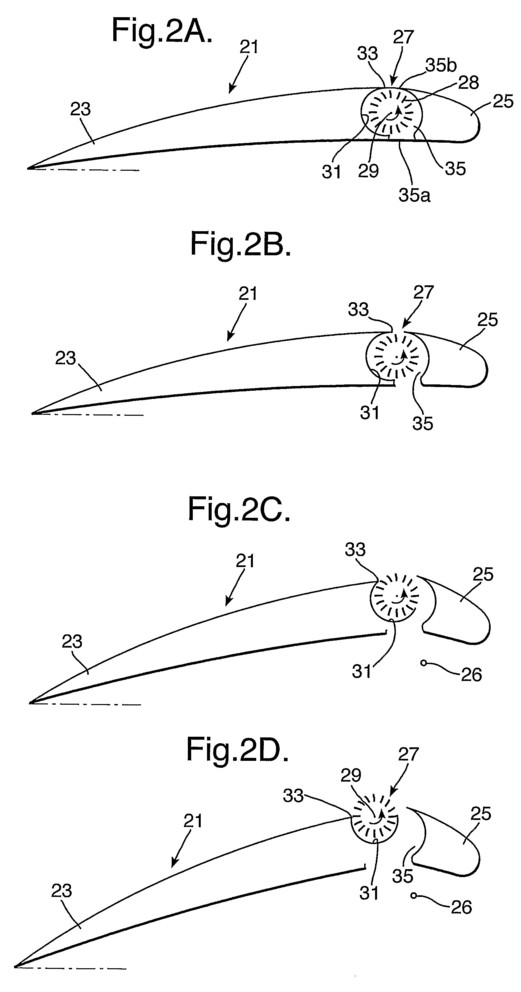
Figure 2B shows the wing of Figure 2A with a slot exposed between the leading edge of the aerofoil and the main wing body, so as to expose the spanwise extending cross-flow rotor to the airflow moving over the upper (convex) and lower (usually concave) surfaces of the wing;
Figure 2C shows the wing of Figures 2A and 2B with the leading edge extended forwardly, in the manner of a leading edge flap, but additionally given a more negative angle of incidence so as to increase the camber of the wing, while at the same time the cross-flow rotor and its vortex-confining shroud are pivoted upwardly so as to cause the upper part of the path of the rotor vanes to project above the convex upper surface of the wing body to encounter the airflow over the convex upper surface of the wing body, during transition from approach speed to landing speed or to augment thrust and lift on take-off;
Figure 2D shows the wing of Figures 2A to 2C with the leading edge portion still further extended and deflected downwardly to further increase the camber of the wing, and with the tangential flow rotor and vortex-confining shroud pivoted still further upwardly to increase the degree of projection of the upper part of the fan vane path above the convex upper surface of the wing for generating high lift at landing ;
Figure 3A shows a third embodiment of a wing in accordance with the present invention, with a vortex-confining shroud incorporated in the front of a trailing edge wing flap and with the wing in clean configuration for cruising on a high speed flight; and

Figure 3B shows the wing of Figure 3A with the trailing edge flap extended rearwardly and deflected downwardly to increase the wing camber and to open a slot between the upper and lower surfaces of the wing through which air passes and generates a vortex in the vortex-confining recess but without the presence of a driven cross-flow fan, for generating high lift at landing.
Referring now to the drawings, Figure 1A shows an aerofoil wing-like body 1 comprising a main aerofoil portion 3 truncated at its trailing edge but supplemented by a trailing portion 5 such that, together, the portions 3 and 5 define an aerofoil section to the wing 1.
Positioned between the main (3) and trailing (5) portions of the wing body is a cross-flow rotor 7 having blades 8 extending spanwise of the wing 1 and able to orbit about a rotation axis 9 extending parallel to the wing span. The part of the rotor facing the trailing wing portion 5 defines a concave recess 11 extending spanwise of the wing 1 and pivotable about an axis 13 close to the convex upper surface of the wing 1 near the leading part of the trailing wing portion 5. In Figure 1A the wing 1 is clean in that the angle of incidence of the trailing wing portion 5 is substantially the same as that of the main wing portion 3 so that the aerofoil of the wing defines continuous surfaces at the junction between the main wing portion 3 and the trailing wing portion 5. In other words the cross-flow rotor 7 is totally isolated from the airflow passing over the convex upper surface and the concave lower surface of the wing 1. In this configuration the wing is configured for high speed flight or cruising flight using a suitable propulsion means.
Figure 1B shows the wing of 1A when adapted for augmenting the lift normally generated by the wing as a consequence of its forward flight. The rotor 7 is shown to be rotating in the anti-clockwise direction about the rotation axis 9, such that the rotor blades 8 and the generated vortex rotate in a direction which causes the airflow in the vortex to be co-current with the main airflow passing over the wing body at a relatively lower pressure side of the wing body and the rotor blades 8 and the flow of the vortex air to be countercurrent with the main airflow over the wing body in the relatively higher pressure region around the wing body. Furthermore the extension of the trailing wing portion 5 rearwardly with respect to the main wing portion 3 has opened a slot between the convex upper surface and the concave lower surface of the wing 1 so as to allow airflow to pass upwardly from the relative higher air pressure region below the wing to the relatively lower air pressure region above the wing. This upward passage of the air through a slot reference 15 is augmented by the rotation of the rotor 7 with its blades 8 moving cocurrent with the airflow through the slot 15.
In the Figure 1B configuration the rotor 7 and the shroud 11 are in the same configuration relative to the trailing wing portion 5 as they are in Figure 1A. There is therefore a degree of lift and thrust augmentation without any undue"dirtying"of the wing configuration in that drag will inevitably be somewhat higher than in the Figure 1A configuration, but will not be increased unduly in that the rotor is still within the overall aerofoil shape of the wing 1 rather than projecting clear of it into the passing airflow. In Figure 1B, the camber of the aerofoil section is somewhat higher than it is in Figure 1A whereas in Figure 2B the camber is unchanged from that of Figure 2A.
In both cases (Figures 1B and 2B) the camber is such that the wing is still substantially as clean as in the cleanest configuration (Figures 1A and 2A respectively).
In the Figure 1B configuration the wing is suitable for transition from high speed or cruising flight to approach speed, or indeed in order to augment lift and thrust for take-off. Just as in WO-A-98/02766 the rotation of the rotor 7 in the anti- clockwise direction shown in Figure 1B may well generate thrust which will augment the general thrust generated by the propulsion means of an aircraft incorporating the wing of Figures 1A to 1D. These propulsion means may for example comprise propellers driven by piston engines, or thrust-generating gas turbine engines, or turbo prop assemblies with propellers driven by gas turbine engines. Other propulsion means may of course be acceptable for use with the wing of Figures 1A to 1D.
Figure 1C shows the wing of Figure 1B with the wing trailing part 5 deflected downwardly so as to increase the overall camber of the wing 1, and now with the vortex-confining shroud 11 displaced slightly relative to the wing trailing body 5 by pivoting anti-clockwise about the pivot axis 13 so as to move the lower part 11 a of the shroud forwardly and upperwardly with respect to the leading edge of the under surface of the trailing part 5, and the rotor 7 is similarly displaced in an anti-clockwise direction relative to the trailing wing portion 5. As a result of this displacement the upper part of the path of the vanes of the cross-flow rotor 7 projects upwardly of the convex upper surface of the wing 1 so as to encounter airflow over the upper surface, moving from the leading edge to trailing edge of the wing 1, and thereby to exert a greater thrusting effect on the airflow as a result of the driven anti-clockwise rotation of the fan rotor 7. This both increases the degree of thrust generated by the rotor 7 and additionally results in attachment of the airflow over a greater length of the upper surface of the trailing wing 5 as a result of the higher airflow over a greater length of the upper surface 5b.
Preferably the rotor rotation axis 9 and the shroud 11 move in unison about the pivot axis 13 so as to maintain a constant positioning between the rotor 7 and the shroud 11 for the purpose of maintaining the quality of the vortex generated within the spanwise extending recess defined by the shroud 11. However, for the purposes of controlling that vortex it may be desirable to cause differential movement of the fan rotation axis 9 and the shroud 11 during this anti-clockwise movement between the position of Figure 1B and that of Figure 1C.
As is clearly visible in Figure 1C, the trailing wing portion 5 has not only pivoted anti-clockwise to increase the camber of the wing 1 but has also been extended further rearwardly with respect of the Figure 1B configuration so as to increase still further the effective wing area of wing 1. In this configuration the wing is well suited for the transition from approach speed to landing speed, or to augment still further thrust and lift for take-off.
The final position, shown in Figure 1D, is one in which the pivoting of the shroud 11 and the fan rotation axis 9 about the pivot axis 13 is still more pronounced so as to increase the degree of projection of the path of the blades of the cross-flow rotor 7 into the rearwardly moving airflow over the convex upper surface of the wing body 1, thereby still further increasing the tendency of the airflow to remain attached over the upper surface 5b of the trailing wing portion 5 and equally still further increasing the thrust effect of the driven rotor 7 on the airflow.
The slot 15 shown in Figure 1C is wider than the corresponding slot discussed above with reference to Figure 1B, and correspondingly that same slot becomes still wider in the Figure 1D configuration. Figure 1D shows the wing in maximum lift configuration for landing.
Although above we refer to the lower surface of the wing as being the concave surface, it will of course be appreciated that not all aerofoils exhibit concave lower surfaces so that undersurface may equally be straight or even mildly convex.
Although the above description refers to the slot 15 being opened as the trailing wing portion 5 moves rearwardly during its extension, it is equally possible for the slot to be opened by retraction of sliding doors which normally close the slot for high speed or cruising flight but which serve to open the slot even before the rearward extension of the trailing wing portion 5 has occurred.
As mentioned above, there is a degree of thrust augmentation as a result of the rotation of the driven fan 7 in the configurations of Figures 1B, 1C and 1D. It is considered that this will enable the main propulsion means to be somewhat rested during the flight in the lower speed regions of the flight envelope, and under certain conditions it may even be possible for all of the thrust to be generated by the rotation of fan rotor 7 so as to dispense with the need for thrust from main propulsion means.
If desired, the shroud 11 may additionally include a control means similar to that disclosed and claimed in GB-A-2346348 for the purposes of controlling the vortex within the generally cylindrical span-wise recess defined by the shroud 11. It has been found that the lift augmentation resulting from the positioning of a cross- flow rotor near the leading edge of a wing-like body (in this case the wing trailing portion 5 which in some ways resembles the wing illustrated in WO A-98/2766), is due to the existence of the vortex within the recess defined by the shroud 11 and at least partially intersecting the path of the vanes of the rotor 7.
Referring now to Figures 2A to 2D, there will be seen an alternative embodiment in which the wing-like member 21 includes a cross-flow rotor 27 between a leading portion 25 defining the leading edge of the wing and a main wing body portion 23 defining the remainder of the aerofoil of the wing. Again, a slot 35 exists between the leading portion 25 and the main wing portion 23, and the forward- facing part of the path of the blades 28 of the fan 27 borders on the slot 35.
In Figure 2A, showing the"clean"configuration of the wing for high speed for cruising flight, the slot 35 is closed off from the region of relatively higher pressure air under the wing body 21 by means of a lower sliding door 35a, and likewise the slot is closed off from the relatively lower pressure region of air above the convex upper surface of the wing body 21 by an upper sliding door 35b. Retraction of these doors into either the leading portion 25 or the main wing portion 23 (in this case the main wing portion 23) opens the slot 35 and allows to pass upwardly through it.
Although the effect of the driven rotation of the cross-flow fan rotor 27 is only exerted on the movement under the wing body 21 when the slot 35 is open, it may of course be desirable to maintain drive to the rotor 27 to keep it rotating about its rotation axis 29 even when the slot is closed, if only for the purposes of ensuring that as soon as the slot begins to open the rotor will already be rotating in the appropriate direction and with the desired speed. For this reason the fan rotor 27 is shown in Figure 2A as rotating in the anti-clockwise direction.
Figure 2B shows a configuration generally equivalent to that illustrated in Figure 1B but in this case there has been substantially no forward movement of the leading wing portion 25, but simply retraction of the two sliding doors 35a and 35b to open the slot 35 to the under and over the wing body 21. This illustrates the configuration for transition from high speed or cruising flight to approach speed. The effect of the vortex within the recess bounded by the shroud 31 is to increase the over the upper surface of the wing body 21, thereby augmenting lift and thrust and maintaining the over the convex upper surface attached until much closer to the trailing edge of the main wing portion 23. Although there would some extent be thrust augmentation as a result of the driving of the upwardly to the slot 35, as with the wing 1 of Figs. 1A to 1D, the effect of thrust augmentation begins to be more noticeable when the configuration of Figure 2C is reached. As in the case of Figure 1C, the shroud 31 has pivoted in the anticlockwise direction about the pivot axis 33, and carried the rotor 27 along with it as is evident from Figure 2C. Thus the upper part of the path of the blades 28 of the fan rotor 27 projects more noticeably into the passing over the upper surface of the wing body 21, increasing the thrust augmentation effect and still further increasing the tendency for the over the upper surface of the wing to remain attached up to the trailing edge.
Figure 2C also illustrates the fact that the wing leading portion 25 has begun to deflect downwardly and, although the mechanism for supporting and guiding the wing leading portion 25 is not shown in the drawings, the theoretical position of the centre of rotation 26 of the movement of the wing leading portion 25 is illustrated both in Figure 2C and in Figure 2D.
As in the case of Figure 1C the position illustrated in Figure 2C applicable to the transition from approach speed to landing speed or for augmenting lift and thrust for take off.
Likewise, configuration in Figure 2D shows still further anticlockwise pivoting of the rotor axis 29 and the shroud 31 about the pivot axis 33 and still further clockwise movement of the wing leading portion 25 to result in both a more negative angle of incidence of the wing leading portion and a further forward extension which increases the effective wing area of the wing 21 for landing.
The embodiment of Figures 2A to 2D has the advantage that the spanwise- extending cross-flow rotor is positioned at the thickest part of the aerofoil section.
Surprisingly it has now been discovered that the existence of the vortex at the recess defined in the leading portion of a wing body may under system circumstances result from without the need for a driving cross-flow fan rotor such as the rotor 7 in Figures 1A to 1D or the rotor 27 in Figures 2A to 2D. Such an arrangement is shown in Figures 3A and 3B where Figure 3B shows the high lift"landing" configuration where the through the slot between the trailing wing portion and the main portion of the wing body itself generates the required vortex.
In particular, Figure 3a shows a wing 41 comprising a main wing body portion 43 and a displaceable trailing wing portion 45 which is displaceable by virtue of pivoting around a theoretical axis 46 shown in both Figure 3A and Figure 3B. In Figure 3A, showing the most clockwise-displaced configuration of the trailing wing portion 45, the geometry is such that there is no slot existing between the main wing body portion 43 and the trailing wing body portion 45. However, once the trailing wing body portion 45 has begun to displace by anticlockwise rotation about the axis 46 from the configuration shown in Figure 3A, that slot 55 is open and is able to pass through the slot upwardly from the relatively higher pressure region below the wing body 41 through the area of relatively lower pressure air above the wing. In doing so, this will generate a vortex rotating in the anticlockwise direction as illustrated by the arrows 56 in Figure 3b, and this vortex is expected to have the same effect of augmenting lift of the wing 41 as was evident with the wing 1 of Figures 1A to 1D and the wing 21 of Figures 2A to 2D, without the need for the cross-flow rotor to generate the vortex.
Although Figure 3B illustrates the position generally equivalent to the configuration shown in Figure 1D, i. e. the high lift"landing"configuration, it will of course be understood that there are other configurations between the extreme of Figures 3A and 3B equivalent to the exemplary configurations shown in Figures 1B and 2B (transition from high speed or cruising flight to approach speed) and Figures 1C and 2C (transition from approach speed to landing speed or showing lift augmentation for take off).
The wing in accordance with the present invention may be used in a"self- propelling"mode which could do away with the need for a separate propulsion means. For example, the wing of Figures 1A to 1D could rely on the Figure 1C configuration for take-off in that the anticlockwise-rotating cross-flow fan 7 will generate a rearward flow of air over the upper surface of the wing trailing part 5 to propel the aircraft forwardly during the take-off run while the intake of air into the slot 15 from beneath the wing will not generate any appreciable rearward reaction (a reaction force acting in the direction towards the trailing edge of the wing trailing body 5). Indeed, the underside of the main wing portion 3 at the rear end near where the slot 15 opens may be shaped so as to facilitate flow of air into the slot 15 in a rearward direction (in a direction from the leading edge to the trailing edge of the wing 1) and, provided the magnitude of the airflow induced by the fan 7 is adequate, there will be a forward thrust on the wing which can cause the aircraft to gather momentum during the take-off run and achieve flying speed. The lift off speed will of course be enhanced (lowered) as a result of the partial downward deflection of the trailing wing part 5, in the manner of the trailing edge wing flap. After take-off the trailing wing portion 5 can be raised into the Figure 1B configuration where the same effect of thrusting flow generated by the cross-flow fan 7 will maintain forward thrust and maintain cruising flight.
For landing purposes, the trailing wing part 5 will initially be lowered to the Figure 1C configuration and then, for final approach, be lowered to the Figure 1D configuration where the maximum CL value will be obtained.
It will of course be appreciated that at no stage will the wing be cleaned up to the Figure 1A configuration, where no such thrusting flow can be generated by the totally enclosed cross-flow fan 7 even if the fan is rotating idly within its shut-off housing defined by the slot 15 on the one hand and the shroud 11 on the other hand.
The same effect can be achieved with the configuration of wing shown in Figures 2A to 2D in that, for take-off purposes, the wing may be set to the Figure 2C configuration so that airflow through the cross-flow fan 7 will be discharged rearwardly over the top surface of the main wing part 23 and taken in from beneath the leading wing part 25 in a generally rearward direction while the configuration of the leading wing part 25 resembles that of a leading edge wing flap. After the take-off phase, the wing can be set to the Figure 2B configuration in which, as in the case of Figure 1B, cruising flight may be maintained with merely the propelling effect of the rearwardly moving air discharged by the cross-flow fan 27 over the top surface of the main wing part 23, optionally assisted by a rearward direction of the airflow into the slot 35 from beneath the leading wing part 25. Again, as in the case of Figures 1A to 1D, the leading wing part 25 may be shaped at its under surface so as to facilitate entry of rearwardly moving air into the slot 35 from beneath the leading wing part 25. Such shaping may, for example, comprise blunting of the"nose"between the underside of the leading wing part 25 and the entry into the slot 35, or even raising of the undersurface of the leading wing part 25 so that it allows the air from beneath the leading wing part 25 to approach the fan rotor in a generally rearward and upward direction.
The Figure 2B configuration can be used for forward flight and the Figure 2C configuration can be used for the early stages of the landing approach, with the Figure 2D configuration used for the final approach where maximum CL values are required.
Although Figures 1A to 1D on the one hand, and Figures 2A to 2D on the other hand, illustrate positions of the cross-flow fan 7 or 27 at points where the transition between the main wing part 3 and the moving trailing wing part 5 of a conventional wing with trailing wing flap will arise (Figure 1B) or where the transition between the main wing part 23 and the leading wing part 25 of a wing with a leading edge flap will arise, this self-propelling configuration just discussed above may be improved by having the cross-flow fan rotor moved somewhat rearwardly from the position showing in Figures 2A to 2D, where the thickest part of the aerofoil will permit the maximum diameter of fan rotor 27 to be accommodated.
As indicated above, the configuration of Figures 1A to 1D showing the displaceable wing trailing portion, and likewise the configuration of Figures 3A and 3B showing such a displaceable trailing portion, are equivalent to a conventional trailing edge flap, and likewise the configuration shown in Figures 2A to 2D is generally equivalent to a conventional leading edge wing flap. However, the lift augmentation device may equally embody other wing configurations and may, for example, be incorporated in a moveable slat to generate a lift-augmenting slot between itself and the adjacent surface of the wing body.
Although throughout the above description the member 1,21 or 41 has been described as"wing-like"this member could be any other dynamic aerofoil plane such as a tailplane or a canard surface.
US6527229
Aerodynamic lift generating device
Aerodynamic lift generating device
2003-03-04
Abstract -- An aircraft has its wing defined as a wing-like body with a tangential flow rotor in the leading edge. A shroud, under the lower part of the tangential flow rotor, terminates in at least one movable flap defining a lift-generating lip when the rotor is rotating such that the upper part of the rotor, projecting above the level of the upper surface of the wing-like body, is moving rearwardly. Differential adjustment of the flaps in the wings to either side of an aircraft centerline allows directional control and control of banking of the aircraft.
BACKGROUND OF THE INVENTION
[0002] The present invention relates to an aerodynamic lift generating device and is an improvement in the lift generating member disclosed and claimed in WO-A-98/07622.
[0003] The device of the above-mentioned International application uses a cross-flow or tangential flow rotor positioned in place of the leading edge of a wing-like body and rotating such that the part of the fan rotor at the top of the wing-like body is moving rearwardly, i.e. towards the trailing edge of the wing-like body, whereas the lower part is moving forwardly. The forwardly moving lower part is shrouded and in various of the embodiments of that earlier device the shroud terminates in a lip which helps to form and locate a vortex within the rotor when the rotor is in motion.
[0004] Lift control, and hence steering and differential lift generation, in that earlier device was envisaged as being effected by a differential gearbox to drive the parts of the rotor to either side of an aircraft centerline at different rotational speeds so as to generate different lift and thrust values to each side of the centerline.
OBJECT OF THE INVENTION
[0005] It is an object of the present invention to provide an alternative means of generating differential lift in such a vehicle.
SUMMARY OF THE INVENTION
[0006] The present invention envisages using a movable flap as the lip at the leading edge of the shroud defining the undersurface of the wing-like body, so that the lip can be either (i) eliminated by positioning the flap flush with the adjacent part of the shroud or (ii) reduced in its degree of intrusion on the space occupied by the rotor by causing it to adopt a position between the optimum vortex-generating configuration and the fully flush position.
[0007] Thus according to a first aspect of the present invention there is provided a lift-generating member comprising:-a wing-like body defining leading and trailing edges and opposed surfaces which converge towards said trailing edge; and a spanwise extending tangential flow rotor positioned adjacent the leading edge of the wing-like body and projecting proud of that one of the opposed surfaces which is uppermost in use of the lift-generating member, whereas the other opposed surface which is the lower one in use of the lift-generating member is defined in part by a shroud which extends forwardly and upwardly and confines the space occupied by the tangential flow rotor and terminates at a lip to define a vortex within the rotor; characterised in that the lip is defined by at least one movable flap which is variable between a first position projecting away from the general direction of the shroud so as to intrude on the space occupied by the rotor and a second position in which it does not intrude to that same extent.
[0008] By positioning the flaps to either side of the aircraft centerline in configurations which differ from one another it is possible for the lift at the side where the flap is "less intrusive" to be reduced as compared with that where it is "more intrusive". Because the vortex influences both lift and thrust it is also conceivable to use the differential lift effect to generate also a yawing movement, preferably such that the difference in lift between the two sides of the aircraft centerline and the difference in thrust on the two sides of the aircraft centerline cause the aircraft to execute a slipless banked turn.
[0009] The control of the angle of the flaps on both wings simultaneously also enables the lift to be rapidly increased or decreased for manoeuvring, either to effect take off and landing or to manoeuver the aircraft in flight.
[0010] It is also possible for the vortex-generating "lip" to be defined by several different flaps at different regions along the span of the wing, so that the turning effect and/or the banking effect can be more finely tuned by selecting for the lift variations a portion of the flap which is at a greater or lesser distance from the aircraft centerline, thereby changing the moment of the differential lift and thrust forces.
BRIEF DESCRIPTION OF THE DRAWINGS
[0011] In order the present invention may more readily be understood the following description is given, merely by way of example, with reference to the accompanying drawings in which:
[0012] FIG. 1 is a top plan view, in schematic form, of an aircraft embodying the present invention;

[0013] FIG. 2 is a side view of the wing of the aircraft in high lift configuration;

[0014] FIG. 3 is a side view of the wing of FIG. 2 in a cruising or normal lift-generating configuration;

[0015] FIGS. 4a and 4b are vertical sectional views of a second embodiment, with the tangential flow fan rotor omitted; and

[0016] FIGS. 5a, 5b, and 5c are views similar to FIGS. 4a and 4b, but showing a third embodiment of the lift generating member of the invention.

DETAILED DESCRIPTION OF THE INVENTION
[0017] FIG. 1 is a schematic plan view of an aircraft 1 comprising a wing body 2 divided into a port wing body 2a and starboard wing body 2b, with a tangential flow rotor 3 which is not shown in detail but which is divided into a port rotor 3a and a starboard rotor 3b, driven by a common drive means. The aircraft has a fuselage comprising a pod 4 and a tail boom 5 which supports a tailplane 6 and a fin 7.
[0018] The underside of the wing body 2 is extended forwardly as a shroud 2' to enclose the cylindrical space 7 occupied by the rotor 3. At the leading edge of the shroud 6 is a pivotable lip-defining flap 8 which is shown in FIG. 2 as intruding on the cylindrical space 7 to its maximum extent. The flap 8 is mounted for pivoting about a pivot defining a pivot axis 8'.
[0019] In rotation of the rotor 3, in the anticlockwise sense as viewed in FIG. 2, the tangential flow in the rotor results in the air expelled from the exposed periphery of the rotor at the front and the top of the wing becoming divided by the nose 9 at the top of the wing-like body 2 such that the expelled air moves downwardly and rearwardly over the upper surface of the wing-like body 2 while the rest of the air moves in the anticlockwise sense within the cylindrical space 7 until it reaches the lip defined by the flap 8 in the FIG. 2 position. As a result an anticlockwise vortex is generated within the rotor and greatly improves the lift force, as described in my WO 98/07622.
[0020] It has been found that in the high lift configuration shown in FIG. 2 the noise generated by the wing and rotor combination is increased as compared with that which would normally be experienced in the cruising configuration shown in FIG. 3 where the flap 8 is in the position 8a substantially flush with the rest of the shroud 2'. In this FIG. 3 position less lift is generated and also less thrust is generated but, provided the flap is as close as possible to the periphery of the fan rotor, the efficiency of the wing is at a maximum. The induced air flow through the rotor in the FIG. 3 configuration is illustrated by the arrows moving along curved streamlines from right to left in the drawing. In the FIG. 2 (high lift) position the flap 8 is even closer to the passing rotor blades than in the FIG. 2 position but must not interfere mechanically with them.
[0021] The difference in lift and thrust can be used in the following manner in order to provide optimum flight conditions.
[0022] For running up the rotor as rapidly as possible on the ground, the rotor drive motor is accelerated while the flap is in the position 8a shown in FIG. 3, thereby minimising resistance to rotation of the rotor. When the rotor has been run up to a desired speed the flap may be moved into its position 8 shown in FIG. 2 and this results in an increase in lift, allowing the aircraft to take off. When the aircraft is stationary the vortex-controlling flap 8 is at its most effective. The aircraft may already have been accelerating forwardly while in the FIG. 3 configuration but generating much less lift, possibly only 20% of the available lift, than it does in the FIG. 2 position.
[0023] In flight, the flap is returned to the position 8a shown in FIG. 3, or to a position close to it, in order to minimize the rotational drag on the rotor, but also to take advantage of the induced lift resulting from the air flow through the rotor and the air flow over the aerofoil wing-like body 2. In order to control the angle of bank and/or the angle of yaw it is possible to vary the position of the flap to a position somewhere between the two extreme positions shown in FIG. 2 and FIG. 3.
[0024] In order to provide for optimum manoeuverability the aircraft may be flown during climb after take off or during approach to landing with the two flaps set midway between the extreme positions shown in FIGS. 2 and 3, such that when bank is needed it is possible to increase the lift from the steady state by increasing the degree of intrusion of the flap on the side where higher lift is required and decreasing the lift on the other wing by similarly reducing the degree of intrusion into the space 7.
[0025] For take off and landing it is advantageous for both wings simultaneously to be in the FIG. 2 configuration, or in a configuration close enough to it to generate high lift and high thrust but still leave some degree of differential adjustability for controlling bank and yaw on landing.
[0026] From the above it will be understood that the rotor 3 may initially tend to slow down somewhat during the take off phase, until the forward speed is such that the air flow through the rotor again assists in reducing the resistance to rotation of the rotor. Thus in the take off phase it is possible to some extent to build up excess rotor speed with the flap in the FIG. 3 position and then to consume some of that energy in the take off phase when the flap moves towards the FIG. 2 configuration and the resistance to rotation of the fan rotor 3 builds up.
[0027] The principle illustrated in FIGS. 2 and 3 can be readily applied to any of the wing cross-sections shown in WO 98/07622, and indeed to any other variations of the basic configuration of the rotor in the leading edge of the wing body.
[0028] If desired and inboard section of each wing (2a, 2b) may have its vortex-generating flap adjustable independently of that as the outboard section so that the inboard section may remain in the high lift configuration during take off and the landing approach, while the outboard section may be adjusted for manoeuvring.
[0029] The embodiment shown in FIGS. 4a and 4b differs from that shown in FIGS. 2 and 3 in that there are two limbs 18a and 18b to the flap, pivotable about a single pivot axis 18'. The two limbs 18a and 18b are at a fixed angle of inclination relative to one another. In the FIG. 4a position the flap limb 18b is substantially a continuation of the shroud 12', while the flap limb 18a is directed inwardly towards the rotor in the position giving maximum lift and thrust (similar to the FIG. 2 configuration).
[0030] In the FIG. 4b configuration this two part flap has pivoted clockwise about the pivot 18' so as (i) to open a gap in the 'shroud' where the flap limb 18b has moved inwardly from it flush position, and (ii) to decrease the extent to which the upper flap limb 18a extends inwardly until it defines the front of the shroud 2'. In this configuration the high speed peripheral air moving forwardly along the inner surface of the shroud will spill out forwardly to reduce both lift and thrust still further as compared with the FIG. 3 configuration, thereby giving more control of differential thrust and lift to improve manoeuvrability of the aircraft.
[0031] In the embodiment of FIGS. 5a, 5b, and 5c the control of this better manoeuvrability embodiment of FIGS. 4a and 4b is still further improved in that an additional facility is provided by virtue of the intermediate configuration of FIG. 5b.
[0032] In the embodiment of FIGS. 5a, 5b and 5c the two limbs 28a and 28b of the flap are to a degree pivotable independently of one another. If desired, complete independence may be provided. For movement from the FIG. 5a configuration to the FIG. 5b configuration the upper flap limb 28a pivots clockwise while the lower flap limb 28b is stationary, until the two limbs 28a and 28b are substantially mutually parallel in the FIG. 5b configuration and substantially flush with the shroud 2'. From then on the two limbs move in unison to reach the FIG. 5c configuration where the two limbs together define the spill passage to allow forward spilling out of the forwardly moving air between the fan rotor and the shroud.
US
6231004
Fluid dynamic lift generation
Fluid dynamic lift generation
Abstract -- An aircraft lifting member (wing) comprises a crossflow rotor 2 formed of a core 4 having rotor vanes 5 mounted around it, disposed in a trough 3 at the front upper part of a wing-like body 1. Rotation of the rotor induces a downwardly and rearwardly directed airflow over the upper surface 6 of the wing-like body 1 generating both lift and thrust. The upper part of the rotor vane path projects above the upper surface 6 and the lift-generating member is open at the leading edge to expose the cross-flow rotor 2 to the incident airflow.
The present invention relates to an improved form of lifting member using a fluid flow, either of an aerodynamic nature or a hydrodynamic nature. It Is particularly useful for an aircraft, and in particular as a high lift wing which will provide both high lift and thrust for a low speed aircraft, making it attractive for STOL (short takeoff and landing) purposes.
In the past STOL aircraft have depended upon either lift augmentation of an aerofoll wing, for example by blown flaps and/or the use of slats and leading edge flaps, and/or upon the use of a tilt wing construction where an engine is mounted fixed in relation to the wing so that tilting the wing to a higher angle of incidence also tilts the engine to give a measure of vectored thrust. Vectored jet thrust in the context of vertical/short take-off and landing (V/STOL) flight is also known.
The present invention aims to provide a novel way of achieving high lift at low forward speed of an aircraft.
GB-A-885888 discloses the use of a cross flow rotor at various locations in an aerofoll body, and includes in FIGS. 27 and 26 a cross-low rotor embedded in the leading edge of the aerofoll body.
In accordance with the present invention there is provided a lift-generating member comprising a wing-like body defining leading and trailing edges and opposed surfaces which converge towards said trailing edge, and a spanwise extending cross-flow rotor positioned adjacent the leading edge and one of said opposed surfaces to define an air intake region and an air discharge region along the circumferential path of the rotor vanes; wherein the rotor rotates in a direction which carries the rotor vanes in the part of their path which is adjacent said one opposed surface in a direction which extends towards the trailing edge of the wing-like body; characterised In that the surface of the rotor projects proud of the said one opposed surface over at least said air discharge region; and in that the rotor is exposed to air at the leading edge of the wing-like body to define a leading edge of the lift-generating member and to take in air at the front of said body and to discharge it over said opposed surface as a result of rotation of the rotor.
By providing for a differential in efficiency between the rotors on either side of the center line of an aircraft it is possible to control the lift differentially, to give a means of banking the aircraft.
If desired, the rotors may provide not just the lift but also all of the thrust which is required for forward propulsion of the aircraft, in which case differential power to either side of the centre line of the aircraft also provides for a measure of yaw control and for a means of controlling the aircraft in a stable banked turn.
In order that the present invention may more readily be understood the following description is given, merely by way of example, with reference to the accompanying drawings, in which:
FIG. 1 is a cross-section through a first embodiment of lifting member in accordance with the present invention;

FIG. 2 is a view similar to FIG. 1 but on a reduced scale and showing a modified form of the wing body of the lifting member;

FIG. 3 is a top plan view of an aircraft incorporating the lifting member of FIG. 1;

FIG. 4 is a table of operating parameters measured using a tethered wing of the design shown in FIG. 1;

FIG. 5 is a graph of rotor input power plotted against lift in grams force;

FIG. 6 is a sectional view of third embodiment of the lifting member according to the invention, shown from the opposite side from that in FIGS. 1 and 2;

FIG. 7 is a view similar to FIG. 6 but showing a fourth embodiment of the lifting member incorporating two alternative forms of flow control (shown on the one drawing for the sake of simplicity);

FIG. 8 is a view similar to FIG. 6 but of a fifth embodiment of the lifting member;

FIG. 9 is a view similar to FIG. 6 but showing a sixth embodiment of lifting member with a more open front to the leading edge crossflow rotor;

FIG. 10 is a view similar to FIG. 6 but showing a seventh embodiment of the lining member with inlet guide vanes to assist flow into the crossflow rotor;

FIG. 11 is a view similar to FIG. 6 but of an eighth embodiment of lifting member according to the invention; and

FIGS. 12a and 12b, respectively, show a ninth embodiment of the lifting member of the present invention, with inlet guide means open in FIG. 12a but closed in FIG. 12b.

The lifting member shown in FIG. 1 uses the combination of a tapered wing-like body 1 and a spanwise extending cylindrical crossflow rotor 2 set into an upwardly open trough-like recess 3 in the front of the wing body 1 near the leading edge 7 of the wing body. As shown In FIG. 1, the crossflow rotor 2 projects upwardly into the airflow passing over the upper surface 6 of the body 1 and it is indeed the rotation of the rotor 2, in the clockwise direction as viewed in FIG. 1, that induces this airflow. The rotor is open to the incident airflow at the front of the lifting member.
FIG. 1 shows that the rotor 2 is a form of crossflow rotor, also known as a tangential flow rotor, extending spanwise along the wing body. In its crudest form the rotor has a succession of discs 9 with high aspect ratio fan vanes 5 extending between the successive discs along the rotor. An optional central shaft 4 connects the various discs together and is driven by the drive means, which preferably includes a differential gearbox mechanism to vary the power distribution between such a lifting member to one side of the aircraft, and a similar such lifting member the other side. Such a rotor will of course be able to be used with any alternative wing body shape such as any of those shown in FIGS. 1, 2 and 6 to 12.
The crossflow rotor 2 rotates clockwise as viewed in FIG. 1 and generates an airflow, shown by the double-headed arrows, deflected upwardly over the upper surface of the rotor core 4 at an air intake region of the rotor blade path and then passing obliquely downwardly from an air discharge region of the rotor blade path to follow the upper surface of the tapering wing body 1. At the trailing edge of the wing body 1 the airflow will detach in the form of a downwardly and rearwardly moving stream which generates a downward component of airflow giving rise to augmented lift of the lifting member, and also a rearward component which generates thrust to induce forward propulsion of the lifting member. Although not shown in FIG. 1, when forward propulsion of the lifting member is established there will be also be an airflow passing under the wing body 1 so that the incident airstream from the left hand side of the lifting member shown in FIG. 1 will divide, with some passing over the rotor and the rest passing under the wing body, and with these two flows recombining, preferably with minimum turbulence, at the trailing edge. This, combined with an aerofoll general shape to the cross-section of the lifting member (wing body 1 and crossflow rotor 2) may also generate aerodynamic lift in the conventional manner.
By increasing the speed of rotation of the rotor its output power can be increased and hence both the lift and the thrust on that lifting member can be increased.
As will be clear from a reading of the following description, there are various other possibilities for designing the spanwise crossflow rotor 2. However, the concept remains the same in that there will be an airflow induced over the wing body giving rise to both lift and thrust.
An aircraft incorporating the lifting member in accordance with the present Invention may have additional thrust-generating means such as at least one engine driven propeller or at least one turbine or rocket engine, but it is envisaged that all of the thrust may be derived from the crossflow rotor 2.
Hence variation of the speed of rotation of the rotor 2 (or its efficiency by means shown in FIGS. 7, 12a and 12b) will not change simply the lift on that lifting members; It may also vary the thrust of that same lifting member to an extent which will allow yaw control of the aircraft having such a lifting member as a wing.
Where this differential lift facility is available it is possible for the aircraft to omit the convention lateral guidance means (such as a rudder) and/or roll control means (for example ailerons).
Although it is possible for ailerons to be omitted in their entirety, it may be helpful to have ailerons present in order to compensate for the de-stabilizing effects of a side-wind on cross-wind lending. Where ailerons are provided, it is expected that they will still produce aileron-induced yaw.
An aircraft using the lifting member of the present invention may include a variable speed drive motor driving a means (such as a differential gearbox) of varying the division of power between the spanwise rotor of the lifting member on the starboard side and the spanwise rotor of the lifting member on the port side, for the purposes of controlling yaw and/or roll.
It is also conceivable for the speed control to be linked to a conventional pitch control means such as a control column normally driving an elevator, so that increasing the motor speed will increase the power to both port and starboard side of the aircraft and hence increase the lift, giving a nose-up tendency, and vice versa. This may either augment or replace the elevator. Alternatively conventional elevator control may be employed, and the speed of the motor diving the rotor 2 may instead be controlled separately In the manner of lift augmentation means such as leading edge and/or trailing edge flaps of a conventional aircraft.
Equally it is possible for there to be a control surface attached to the wing body 1, for example of the trailing edge, in order to vary the aerodynamic camber of that wing body for the purposes of further augmenting lift.
If desired the wing body member 1 of FIG. 1 may have the trailing edge occurring at the end of a sharper taper zone starting at a point on the upper surface of the tapering wing body. In this case the undersurface of the wing body may be a continuous planar surface as shown in FIG. 1. However alternatively the undersurface could equally include a point of discontinuity (similar to such a point of the upper surface) at which the angle of inclination of the lower surface either increases or decreases.
Also, the trailing edge may be at the end of a downwardly curved portion of the wing body to impart aerofoll camber to the wing today, resulting from the curvature of the part of the wing body behind the trough 3 and rotor 2. The upper surface may be convex overall (so that for the entire wing body can be of curved form with a generally aerofoll configuration) or may become convex after a point marking the termination of a forward generally planar upper surface. (It will of course be appreciated that the downwardly curved portion may be in the form of a succession of generally planar surfaces giving rise to a succession of stepped regions of different inclinations to resemble such a curved configuration).
In all of the embodiments the vanes may form a close non-interference fit with the concave part-cylindrical wall of the wing body defining the trough 3.
In the preferred embodiment shown in FIG. 1, the rotor discs 9 have a diameter of 80 mm. Between two successive rotor discs 9 along the span of the lifting member are 16 rotor vanes 5, in this case each of 10 mm chord and 0.6 mm thickness. The blades are part-cylindrical curved sheets having a 30 mm radius of curvature. This is the design of prototype used for the tests whose results are shown in FIGS. 4 and 5.
In this case the trough 3 is part-cylindrical and has the discs 9 fitting closely within it. It extends over 155 DEG of arc of the cylinder defining the trough. Thus, as viewed in FIG. 1, the left hand- or leading edge-side of the wing body member is cut away at 7 to expose the rotor to the incident airflow.
As shown in FIG. 1, the rotor vanes 5 are in this case set at an angle of 30 DEG with respect to that radius which also passes through the edge of the rotor vane 5 lying farthest from the shaft 4. It may also be of value to control the angle of these blades while the rotor is turning. This could be in the form of collective pitch which would change the angle of all the blades at the same time or in the form of cyclic pitch control which would control the angle of the blades depending on their position relative to the wing body.
FIG. 2 shows a variant, generally similar to the embodiment of FIG. 1, but with a slat or cover 8 over the rotor to define a slot to control the airflow over the upper surface of the lifting member.
A model incorporating the design shown in FIG. 1 has been run using direct drive to the rotors to each side of the fuselage centre line of the model. Such a model is shown in plan view in FIG. 3 as comprising a fuselage 20 having a fixed tail plane 21 and a port wing body 22a and a starboard wing body 22b. In this case a fin or vertical stabilizer 23 has also been mounted on a tail 24 of the model. The rotor has been omitted from FIG. 3 but the trough 3a and 3b of the respective wing member 22a and 22b is illustrated. It is thus possible to visualise the way in which the lifting body cross-section of FIG. 1 has been adapted to the model aircraft.
The model has an all up weight of 3.4 Kg which includes a 1 horse power motor of 5 cc displacement. The wing span of the model is 206 cm, and this comprises two active wing bodies 22a and 22b each of 93 cm span.
The model was flown in radio-controlled free flight. The airspeeds and power values (see FIGS. 4 and 5) were extrapolated using the test results of a 90 cm span tethered wing prototype of the wing body of FIG. 1.
For take-off the motor was running at one-third of its maximum power. Stable flight speed was measured as approximately 5.5 metres per second.
A similar tethered test was carried out using a single lifting member, of the type shown in FIG. 1 with its rotor 2 driven by an electric motor, mounted on a mast and counterbalanced by a mass arm. With such an apparatus the various parameters shown in FIG. 4 were determined. They are as follows:
V represents the voltage applied to the motor.
A represents the motor current in amps.
The third column shows the rotor speed in r.p.m..
W represents the rotor input power in watts.
The fifth column represents the forward (propulsive) thrust measured when the lifting member was held stationary, i.e. not allowed to orbit the mast.
The sixth column shows the average time to complete one revolution about the mast, when in the steady state.
The seventh column tabulates the lift force in grams.
The eighth column is the quotient of lift (gm) divided by rotor input power (watts) (i.e. the value in the seventh column divided by the value in the fourth column).
The ninth column illustrates the ratio of static thrust:lift (static thrust as shown in the fifth column, and lift as measured while the wing was in motion) for each value of the rotor speed and power quoted in the third and fourth columns.
FIG. 5 illustrates a plot of the input power of the rotor measured in watts, as the ordinate, and the lift in grams measured as the abscissa. The points correspond to the measured values tabulated in FIG. 4, and the straight line illustrates the theoretical (compromise) plot and can be seen to be a nearly straight line.
In other words, the efficiency of the lifting member shown in FIG. 1 appears to be constant over the range of rotor speeds tested, and over the orbiting speeds encountered.
There are of course various alternative possibilities for the geometry of the rotor used with the device of FIG. 1. For example, the thickness and chord values of the rotor vanes 5 may be varied. The angle of incidence (30 DEG in FIG. 1) of the rotor vanes may be changed. Also, the angle of are subtended by the trough 3 may be varied.
With the device shown in FIG. 1 it has been discovered that, for a given rotor speed, the lift tends to increase as the speed increases. Bearing in mind that the vertical projection P1 of the part of the rotor on which the incident air impinges is much greater than the projection P2 on to a line normal to the upper surface 6 of the wing body, it is possible that there is some form of compressibility effect generated through the ram effect of the incident air arriving at the rotor area exposed at the front of the lifting member.
The included angle of taper of the wing body 1 of FIG. 1 is approximately 45 DEG . However, this can be varied. The air discharged tangentially from the rotor thus follows a direction approximately 45 DEG to the vertical, giving substantial lift and thrust components.
Various alternative forms of the lifting member 1 are shown in FIGS. 6 to 12 as follows:
In these various drawings the direction of the airflow relative to the lifting wing is from right to left whereas in FIGS. 1 and 2 it was from left to right. In each view the direction of rotation of the crossflow rotor is illustrated by a single headed arrow and in FIG. 6 a vortex airflow within the rotor is illustrated by doubled headed arrows, with the centre of the vortex being designated v, but in practice the position of the vortex will be located by experiment if the position of the centre needs to be known.
It is known that the efficiency of the crossflow rotor increases with the establishment of a vortex within and eccentric to the path of the rotor vanes, and rotating at an angular velocity much higher than that of the rotor and in the same direction of rotation. The establishment of such a vortex is enhanced by various means shown in FIGS. 6 to 12.
In FIG. 6 the shroud 3 has its front end turned inward at 3a, and the result of this is the formation of a vortex centred within the rotor and having the direction of rotation indicated by the double headed arrows. FIG. 6 also illustrates the angle of incidence .varies. a of the wing body 1 measured in terms of the inclination of the underside of the wing body.
FIG. 7 shows a departure from FIG. 6 in that the underside of the wing body 1 is concave to impart a degree of camber to the wing body, but furthermore the wing body of FIG. 7 has additional control features. At the front end of the shroud 3 is a movable baffle 11 which can be retracted to the position shown in FIG. 7 to allow maximum airflow into the rotor or can be extended upwardly and rightwardly so as to mask the inlet of the rotor to some extent, and thus to control the efficiency of that particular lifting body.
Also shown in FIG. 7 is a movable spoiler 12 which is illustrated in FIG. 7 as being extended so as to attenuate or to destroy the vortex. This again provides a measure of control of the efficiency of the lifting body.
It is envisaged that the baffle 11 and the spoiler 12 would be able to be used independently of one another, or together in the same embodiment, and for the sake of simplicity they have been shown in FIG. 7 as both being present. In FIG. 7 the shroud 3 is no longer concentric with the rotor 2 but has its end points 3b and 3c closer to the path of the vanes 5 of the rotor than is the shroud at a point between them (for example where the spoiler 12 is mounted), and this helps to generate the vortex provided either there is no spoiler 12 present or that spoiler has been moved anticlockwise from the FIG. 7 position to lie flush with the shroud 3.
FIG. 8 again has the shroud 3 non-concentric between the points 3b and 3c, in order to establish the vortex, but in this case there is a forward extension 3d of the shroud from the point 3b and substantially concentric with the rotor vane path.
On the other hand, FIG. 9 lacks this forward extension 3d and provides a more open construction which, for a given speed of rotation of the crossflow rotor 2, is able to admit and discharge a greater volume flow rate of air than with the FIG. 8 embodiment.
FIG. 10 provides for a larger air inlet area and relies on a bulge 1a of the lifting body 1 to define the necessary non-concentric portion, even though in this case there is no shroud as such. The formation of the vortex results from the cut away configuration of the part of the lifting body 1 facing the crossflow rotor 2. Towards the lower leading part 1b of the lifting body 1 is a concave section which, together with guide vanes 15, defines an inlet path or nozzle to guide incident air into the rotor blade path and hence to establish better the vortex and the flow through the crossflow rotor.
FIG. 11 again uses a bulge 1a, but this time positioned much higher on the lifting body 1 so that the air inlet "nozzles" defined by the convex surface of the lifting body 1 between bulge 1a and front 1b; also the two guide vanes 15 are much longer than in the FIG. 10 embodiment. This appears to give the most open configuration of the rotor, allowing the best possible flow conditions through the rotor.
FIGS. 12a and 12b illustrate an alternative form of the lifting body 1 in which the inlet configuration can be altered in flight to control the efficiency of the lifting body. FIG. 12a shows a set of four straight inlet guide vanes 17, pivotable about their respective shafts 18, between the open position shown in FIG. 12a and a closed position shown in FIG. 12b. The lifting body 1 does have a vestige of the shroud 3, and it is possible to liken the inlet guide vanes 17 in their FIG. 12a position to the inlet guide vanes 15 of FIGS. 10 and 11, and in their closed (12b) position to the shroud extension 3d of FIG. 8 or the shrouds 3 of FIGS. 6 and 7.
Although only FIGS. 7 and 10 illustrate camber of the lifting wing body by means of a concave underside, it would of course be appreciated that any of the embodiments shown may have such a concave underside and/or a convex upper surface (6 in FIG. 1) to impart camber to the body.
Although the above description is based on a lifting member for an aircraft, there are various other possibilities. It may be that the device may have hydrodynamic applications, for example in propelling boats using such a member as an immersed keel or a hydrofoil wing.
In the aerodynamic field, the device may also be used for propelling and controlling boats using the aerodynamic effect rather than the hydrodynamic thrust of an immersed screw.
When used as the lifting wing for an aircraft, as mentioned above it is possible for other thrust means to be omitted and for the airflow generated by the rotor to provide all of both thrust and lift. With reference to the (model) aircraft depicted in FIG. 3, the drive motor for the rotors may operate such that pushing the control column to the left (port) will cause the rotor(s) of the starboard side lift-generating member to rotate faster than the rotor(s) on the port side, giving controllable roll and yaw to allow a balanced banked turn to be executed. There may still be a rudder to provide for the yaw, in which case this will be connected to the pilot's foot pedals. There may equally be some interconnection between the foot pedals and the speed differential mechanism, so that at high rotor powers there will be less rudder deflection needed for a given degree of yaw.
The elevator may be dispensed with but is more likely to be present and controlled by a trim lever rather than by rearward movement of the control column.
An aircraft incorporating such a lifting member will provide adequate degrees of lift at low speeds and will therefore have good STOL characteristics. The noise generated will be much lower than that of a conventional jet or propeller-driven machine. Because a large quantity of air is moving at a very low speed through the rotor the rotor blades themselves move slower than a conventional driving propeller so the blade noise can be much lower than that of a propeller.
In order to reduce noise levels still further it may be advantageous to shape the rotor vanes 5 so as to follow the path of a very coarse pitch helix about the axis of rotation of the shaft 4 so that they are nearly, but not quite, straight. This may avoid any tendency for a sudden noise to be created as each blade enters the trough at the trailing edge of the trough because whereas a straight blade parallel to that trough trailing edge will pass the trough edge at a single instant, a slightly helical blade will not but will instead have a point of approach which travels along the span of the wing body 1 (rather like the shearing action of the rotary blades of a cylinder mower passing a stationary straight blade).
An aeroplane incorporating such a lifting member will, for example, be applicable to sport and tourism in that an open-cockpit aircraft can be constructed to fly slowly and quietly using such a system. Equally, it can be useful for carrying loads over short distances (in view of its low flying speed). Furthermore, it can be useful for crop-dusting.
For passenger transport it may be particularly convenient to use this as a shuttle craft between nearby airports.
In the event of engine failure the spanwise rotors may be driven in autorotation by the airflow, so that recovery from a loss of lift would require simply an increase in forward speed, in a dive, and then, on nearing the ground, flattening out the flight path to exploit the kinetic energy of the rotor somewhat like the case of engine-off autorotation of a helicopter.