Jörg
HEMPEL
Ionic Magnetic Power Charger
Ionic Magnetic Power Charger
Charges/discharges
capacitors in a magnetic field much more quickly, depending
on the field polarity.
US 2010159293
DEVICE FOR PRODUCING ELECTRICAL ENERGY AND A CHARGING CURRENT SIGNAL...
DEVICE FOR PRODUCING ELECTRICAL ENERGY AND A CHARGING CURRENT SIGNAL...
Abstract -- A device for producing electrical energy having at least one ion cell can produce a magnetic field at the location of the at least one ion cell and also has at least one capacitance or an interconnection of at least two electrically connected capacitances, of which two contacts of counter pole electrodes are connected to the counter pole electrodes of the at least one ion cell, and a consumer load may be connected in parallel to the capacitance and the interconnection of capacitances, respectively.
BACKGROUND
[0001] 1. Field
[0002] The disclosed embodiments relate to a device for producing electrical energy, as well as to a novel charging current signal and a device for producing electrical energy charged by the charging current signal.
[0003] 2. Brief Description of Related Developments
[0004] It is known to use ion cells in electrochemical current sources. An ion cell or several ion cells (also called galvanic cells) connected in series are referred to as a battery. Ion cells convert the chemical energy stored in them directly into electrical energy. The reaction supplying the energy, the discharge, is composed of two partial reactions (electrode reactions) which are spatially separated but coupled to each other. The electrode in which the corresponding partial reaction takes place at a lower redox potential in comparison to the other electrode is the negative electrode (-), the other one is the positive electrode (+). During the discharge of the ion cell an oxidation process occurs at the negative electrode by which electrodes are released; in parallel thereto a corresponding amount of electrodes is collected at the positive electrode via a reduction process. The electrode current flows from (-) to (+) through an external consumer load circuit. Inside the ion cell, the current is carried by ions between the electrodes in an ionically conducting electrolyte (ion current), with ion and electron reactions being coupled to each other in/at the electrode.
[0005] A difference is made between primary cells that use themselves up during their discharge, and rechargeable cells, which are also called accumulators, in which the electrochemical discharge reactions can be reversed to a large extent so that a multiple conversion from chemical into electrical energy and back may take place. During these discharging/charging cycles alternate oxidation and reduction processes are performed at each electrode so that one must be careful when using the designation anode or cathode, which are defined by the terms of oxidation or reduction. This problem can be avoided by using the terms of negative electrode or positive electrode because the respective electrode potential in a normal charging/discharging operation always remains more negative or positive than that of the other electrode. In parallel thereto, however, there is the convention that the electrodes are named in accordance with their function during the discharge, that is, the negative electrode is referred to as the anode and the positive electrode is referred to as the cathode.
[0006] Generally, an ion cell in a battery or an accumulator consists of one electrolyte, two electrodes arranged together in a battery casing, which may include a plurality of ion cells, and separators that are permeable to ions but impermeable to electrons and with which it is possible to avoid a short circuit due to internal electrode contact. The so-called active materials are the actual storages of the chemical energy in the battery or the accumulator. The electrical energy is released during the discharge due to its electrochemical turnover at the electrodes. The number of electrodes released or collected in this process per unit of mass or volume determines the storage capacity of the active electrode material and is indicated as the specific load (in Ah kg<-1>) and charge density (in Ah cm<-3>), respectively.
[0007] Widely used accumulators of this kind are lithium ion accumulators which are particularly used in portable devices of high energy demand, such as, for example, in mobile phones, digital cameras, camcorders, laptops or the like, as well as in electric and hybrid vehicles. At present, they are also increasingly used in electric tools, such as cordless screwdrivers, for example, due to their high charge density.
[0008] In an accumulator electrical energy is converted into chemical energy during the charging. If a consumer load is connected, the chemical energy is converted back into electrical energy. Furthermore, when accumulators are charged and discharged, heat is released by which a part of the energy used for charging is lost. In conventional accumulators, the charging efficiency, that is, the ratio of the withdrawable energy to the energy to be used for charging, is normally about 60 to 95 percent.
[0009] Usually, optimal charging of different types of accumulators is effected with not-too-high charging currents over a comparatively long period of time. A 20-hour charging of a lead accumulator used as a car battery, for example, is to be given preference over a fast charging within a few hours with higher charging currents because the latter may reduce the efficiency and the service life of the lead accumulator.
SUMMARY
[0010] It is the object of the disclosed embodiments to improve the efficiency of devices for producing electrical energy with ion cells as well as to provide a novel charging current signal and a device for producing electrical energy with which the charging efficiency of galvanic cells and electrolyte capacitors is considerably enhanced and the charging time may be substantially reduced.
[0011] This object is achieved by means of devices for producing electrical energy according to claims 1, 20, 21, 24, and 28.
[0012] Features of preferred aspects of the disclosed embodiments are characterized in the subclaims.
[0013] According to one aspect of the disclosed embodiments, the device comprises: at least one ion cell, means for producing a magnetic field at the location of the at least one ion cell and at least one capacitance or an interconnection of at least two capacitances, of which two contacts of counter pole electrodes are connected to the counter pole electrodes of the at least one ion cell, and a consumer load may be connected in parallel to the capacitance or the interconnection of capacitances.
[0014] In a first series of experiments with aspects of the disclosed embodiments an energy output of the device which cannot be explained by the state of knowledge of current research regarding the duration as well as the performance was observed and measured.
[0015] Furthermore, the aspects of the disclosed embodiments are based on the observation that the application of a magnetic field to an ion cell, in particular a lithium ion cell, leads to the fact that the current withdrawn from this cell has properties which cannot merely be characterized by the current intensity.
[0016] It was found that the current produced in this manner is particularly suitable for charge separation in galvanic cells, that is, in other words, for charging galvanic cells or for charging electrolytic capacitors. As the current thus produced effects a charge separation in a galvanic cell or an electrolytic capacitor, as will be explained below in more detail by means of a description of an experiment, which charge separation is not correlated to the amount of the supply of electrical energy following current physical findings, this charging current will be referred to in the following as charging current signal. A galvanic cell upon which such a charging current signal acts shows a charging behavior which is optimized as to charging time and charging current to be provided.
BRIEF DESCRIPTION OF THE DRAWINGS
[0017] Below, the aspects of the disclosed embodiments will be explained in more detail by means of the description of embodiments and experiments with reference to the drawings, wherein:
[0018] FIG. 1 is a circuit diagram of a first embodiment of the present invention;

[0019] FIG. 2a is a second embodiment of the present invention;

[0020] FIG. 2b is a variant of the embodiment shown in FIG. 2a;
[0021] FIG. 3 is a perspective exploded view of an array of permanent magnet strips on a series connection of ion cells; and

[0022] FIG. 4 is another embodiment of the present invention.

DETAILED DESCRIPTION OF THE DISCLOSED EMBODIMENTS
[0023] FIG. 1 shows one embodiment of a device for producing electrical energy. In this embodiment six ion cells 1 are connected in series. A permanent magnet 2 is mounted as closely as possible, for example, to the casing walls of the ion cells 1 so that all ion cells 1 are permeated by the magnetic field produced by the permanent magnet 2. An embodiment of the attachment of permanent magnets is shown in FIG. 3, as described further below.
[0024] A capacitor bank consisting of four capacitors 3a to 3d connected in parallel and a load 4 are connected to the series connection of the ion cells 1. As has been found, the four capacitors connected in parallel together can be charged faster than a corresponding capacitor of the same capacity as the sum of the capacities of the capacitors connected in parallel.
[0025] In the following, a first experiment will be described which was carried out with the following means:
[0026] The accumulators were each liberated of associated electronics by which a deep-discharge is to be avoided. These were commercially available lithium ion accumulators having a nominal capacity of 750 mAh as are used, for example, in mobile phones or laptops. Six lithium ion accumulators were connected in series and deep-discharged. The deep-discharge was at first made by coupling a consumer load in order to achieve a slow discharge and at the end the series connection was short-circuited. A measurement of the voltage showed that no voltage could be measured at the accumulator series connection. The capacitors used during the experiment were electrolyte capacitors connected in parallel to form a capacitor bank. In this case the capacitor bank was also at first short-circuited to ensure that there is no charge in the capacitors. Subsequently, the ion cell battery was provided with permanent magnets, as shown in FIG. 3. Here, they are commercially available magnetic strips of a width of about 1 cm, on the outer edges of which a magnetized substance had been attached in parallel to the longitudinal extension of the strips. The polarities of the magnets running parallel to each other were opposed.
[0027] The battery unit combined into a block of accumulators arranged in parallel to each other was surrounded by the magnetic strips.
[0028] Next, the deep-discharged lithium ion accumulator series connection was connected to the corresponding poles of the capacitor bank.
[0029] Completely surprisingly and unexpectedly, a voltage of 23.8 V built up between the poles of the accumulator series connection after about 10 s. After separating the capacitor bank from the accumulator array and short-circuiting until the voltage level dropped to zero, a voltage of 33 V built up again contrary to expectations between the poles of the capacitor bank after about 90 s.
[0030] This is all the more astonishing since electrolytic capacitors usually have no charge remanence.
[0031] Finally, the accumulator series connection was connected to the capacitor bank 3a-3d and in turn a load 4 was connected thereto. In the experiment as carried out the load 4 consisted of a DC motor having a nominal voltage of 40 V and a no-load current of 0.8 A as well as an Imax of 6.3 A. In the experiment as carried out, the motor was supplied with a voltage of 12 V. The permanent current consumption resulting therefrom was 80 mA. The motor started and soon achieved a constant speed at which it ran for 144 hours in a long-time test. According to expectations, using a conventional, fully charged accumulator the motor would have had to stop after a few hours at the latest due to a lack of sufficient applied voltage; in this case, however, a deep-discharged accumulator array was used in which a voltage rise was observed and measured during the current consumption in the course of time instead of a voltage drop.
[0032] During the power consumption neither the capacitors nor the accumulator series connection heated up noticeably.
[0033] Furthermore, the following phenomena were observed in this array. The accumulator array was separated from the capacitor bank and discharged for a few seconds by short-circuiting. After connecting the capacitor bank to the accumulator array the capacitors were charged within a very short time (on the order of 0.5 s).
[0034] The capacitor bank was discharged by means of a filler wire having a cross-sectional area of 1 mm<2>. The discharge process was very rapid, i.e. within a few milliseconds, with a high current that melted the filler wire, and a formation of sparks.
[0035] FIG. 2a shows another embodiment in which the permanent magnet 2 was replaced by a wire-wound coil. The coil 5 is wound around the accumulator series connection and connected in series to the capacitance. Thus, an electromagnet is formed and the accumulators are aligned in parallel to the axis of the electromagnet in the axial direction thereof.
[0036] FIG. 2b shows a detail of another embodiment in which the electromagnet coil 5 is fed by an external current source.
[0037] Furthermore, the embodiment shown in FIG. 2a has a change-over switch 6 by which the accumulator series connection is alternately connected to the capacitor bank 3a-3c or to the load 4. By switching the change-over switch 6 either the capacitor bank is charged by the accumulator series connection or the load 4 is fed by the capacitor bank.
[0038] The switching frequency of the change-over switch is suitably selected so that the capacitors 3a-3c are discharged by a maximum of 20 to 30%, i.e., after the discharge they still have a residual charge of 70 to 80% of their maximally storable charge. The charging of the capacitors takes place faster in this charging range than in the case when the capacitors would be discharged to a lower level per cycle.
[0039] FIG. 4 shows another embodiment in which, in the case as shown, two capacitor banks 3a, 3b, . . . and 7a, 7b . . . are alternatively connected in a clocked manner to the accumulator array by the change-over switches 8a, 8b. Moreover, a capacitor bank 10 is connected in parallel to the accumulator array.
[0040] Likewise, it is conceivable to connect more than two capacitor banks in sequence to the accumulator array.
[0041] Furthermore, it should be noted that it is also possible to use non-discharged accumulators instead of deep-discharged accumulators.
[0042] Due to the device for producing electrical energy according to the aspects of the disclosed embodiments, it is possible to implement applications which open up previously unreached dimensions as regards the power output as well as the ambition to make energy sources more compact and lighter.
[0043] In the following, a second experiment will be described which was carried out with the following means:
[0044] A motorbike battery, in this case a lead accumulator having a rated voltage of 12 V and a capacitance of 12 Ah, was slowly discharged via a consumer load until the terminal voltage was only about 3 V. The discharge was made with a small discharging current so that the motorbike battery did not noticeably heat up.
[0045] Then the motorbike battery was connected for recharging to four series-connected lithium ion accumulators prepared with magnetic strips. The device for producing electrical energy using lithium ion accumulators described in the present patent application comprises an array of one or more electrolytic capacitor(s) connected in parallel to the series connection of lithium ion accumulators. Such electrolytic capacitors may be used as intermediate storages of electrical energy in the experiment described here, however, they are not compulsory.
[0046] In the experiment described here, a series connection comprising permanent magnet strips of prepared lithium ion accumulators without electrolytic capacitors connected in parallel was used.
[0047] In order to charge the motorbike battery, the above-described lithium ion accumulator array was connected to the battery. After about 20 minutes the motorbike battery was fully charged and showed a voltage of about 14 V, that is, 2 V above its rated voltage, at its terminals. The surprisingly short time until the full charge of the motorbike battery allows the conclusion that a very high charging current has flown during this time. It turned out to be difficult to measure the current directly by inserting a digital multimeter measurement apparatus into the circuit because the charging time strongly increased for unknown reasons until the motorbike battery was fully charged.
[0048] Nevertheless, in order to get an idea of the dimension of the charging current, the charging cable was cut through at one spot and the gap in the circuit was bridged by cable portions of different cross-sectional areas. The discharging and charging process, as described above, was repeated several times and the very short charging time of between 2 and 20 minutes respectively appeared again. The most astonishing fact, however, was that even when the circuit gap was bridged by a "telephone wire" having a cross-sectional area of about 0.75 mm<2 >and a length of about 20 cm, the wire did not heat up beyond room temperature. Thus, it is certain that during the charging of the lead accumulator no current corresponding to the amount of energy which the lead accumulator regained after the recharging process flew within the short charging time. The charging current required for this purpose would have had to be so large within the short charging time that it would have made the "telephone wire" melt without fail. The wire, however, did not even heat up.
[0049] This allows the conclusion that in case of the above-described charging process electrical energy is not transferred from an electrical energy source to a galvanic storage for electrical energy, as usual, which can then be withdrawn again after subtraction of the energy converted into reaction heat, but that the charging current, referred to as charging current signal below, merely "triggers" the galvanic cell, that is, the chemical reaction which occurs in the galvanic cell is merely initiated by the charging current signal and not maintained by a corresponding addition of electrical energy.
[0050] It is a fact that the described technical effect, namely the fast chargeability of a galvanic cell with the charging current signal produced as described above and the inexplicably high charging efficiency may be reproducibly imitated in the manner as described above, as proven by the multitude of successfully performed experiments.
WO 2010102791
CHARGING CURRENT SIGNAL AND DEVICE CHARGED WITH SAID CHARGING CURRENT SIGNAL FOR GENERATING ELECTRIC ENERGY
CHARGING CURRENT SIGNAL AND DEVICE CHARGED WITH SAID CHARGING CURRENT SIGNAL FOR GENERATING ELECTRIC ENERGY
Abstract -- The invention relates to a charging current signal for causing a separation of charge in a galvanic cell or electrolytic capacitor, generated by a device located in a magnetic field at least for a predetermined period of time, having two electrodes in one electrolyte, separated by a separator impermeable to electrons.
WO
2010063453 (A1)
METHOD FOR REFORMING ELECTROLYTIC CAPACITORS
METHOD FOR REFORMING ELECTROLYTIC CAPACITORS
Abstract -- The invention relates to a method for reforming electrolytic capacitors, comprising the following steps: a) if the electrolytic capacitor exhibits a load, slowly discharging via a suitably dimensioned load; b) charging of the electrolytic capacitor by applying a voltage increasing in steps, wherein each voltage increase step equals a fraction of the nominal voltage of the electrolytic capacitor, wherein the voltage is then increased by one step when the charge current at the current step has dropped substantially to zero, and wherein the stepped increase of charge voltage is continued until the charge current no longer drops to zero.

The present invention concerns a method to the reforming of electrolytic capacitors.
Electrolytic capacitors become used, if very large capacitance values are required. This is for example the case with power supplies, NF-final stages and such a thing. In automotive electronics engine management systems for the fuel injection, drives of Kühlerund windshield wiper motors, electronic steering systems, airbags or Multimediageräte and such a thing rank among the applications.
With an electrolytic capacitor (also Elko mentioned) a non conductive insulating layer becomes generated on the metal of the anode electrode by electrolysis (anodic oxidation, formation), which forms the dielectric of the capacitor. The electrolyte forms the cathode (counter electrode) of the electrolytic capacitor. It can consist of liquid or pasty electrolytes (ion leaders) or solid electrolytes (electron conductor). The power supply to electrolytes of made over films same metal as that the anode or over a suitable contact electrolytes.
At present common types from electrolytic capacitors are: Aluminum electrolytic capacitors with alumina as dielectric, tantalum electrolytic capacitors with Tantalp entoxid as dielectric, niobium
669-68567PCT/CM electrolytic capacitors with Niobpentoxid as dielectric as well as so called “gold Caps” or “Super Caps”.
The anode of the electrolytic capacitor becomes the magnification of the surface structured, with aluminum Elkos is it a aufgeraute anode foil, with tantalum Elkos a sintered metal sponge. Due to the large surface area and the extremely thin dielectric relative high electric capacitances of the order of magnitude of 1 F can become achieved with electrolytic capacitors with small construction.
With “gold Caps” and “Super Caps” reach the capacities the order of magnitude of 2OF, however with relative small rated voltages of some few volts.
For example a aufgerauten aluminium foil as anode material one calls electrolytic oxidizing forming. This happens for the first time with the preparation of electrolytic capacitors on the end of the manufacturing process in the factory.
Electrolytic capacitors have the disadvantage of high leakage current losses by the remainder conductivity of the dielectric. If an electrolytic capacitor does not become longer time used, it unloads itself by the leakage current complete. This state is harmful for the insulation resistance of the dielectric, to the maintenance and/or. for the reproviding of an high insulation resistance of the dielectric forms new and/or. to be after-formed must.
Reforming for electrolytic capacitors have always had the object to regenerate the dielectric in order to thus show the electrolytic capacitor its original qualities such as capacity and copy voltage level.
From US 4.974, 118 A is an apparatus known, with which reforming of the type performed here standing in speech to become to be able.
2007/025057 a2 describe the reforming for capacitors incorporated in medical implants. Afterwards will empirical determined condenser load data of the used capacitors used, in order to determine the Nachformierungszeit which can be used, in which the capacitors are loaded on a voltage, which corresponds to 20% to 90% of the rated voltage.
The DE 19 50 967 has a method to the reforming from electrolytic capacitors to the subject-matter, with which during the reforming of these at least once, preferably several times by shutdown of a direct current source interrupted will and a simultaneous electrical discharging resistor becomes parallel the capacitor connected, over which the capacitor wenigsgtens partly unloads itself, so that a polarization of the anode arising with the preceding charge of the capacitor becomes sufficient destroyed made by the mentioned discharge.
DE 23 60 688 A is a method to the reforming of electrolytic capacitors known, with which in steps to the capacitor the applied voltage increased will and a constant current held becomes for each step so selected that the maximum voltage preferably becomes for each step in less than 20 seconds achieved.
The present invention is the basis the object to indicate a method to the reforming of electrolytic capacitors as that the leakage current after-formed electrolyte condensates on a negligible measure of the reduced and the disruptive strength and/or the rated voltage increased to become to be able, whereby higher charge quantities in the electrolytic capacitor stored to become to be able.
This object becomes 1 dissolved with the features of the claim.
Features of preferred embodiments of the present invention are in the characterized in the description.
With the invention process after-formed electrolytic capacitors shown no self discharge considerable in the test series also after several days and the breakdown voltage effected that the rated voltage and thus the storable charge quantity did not after-form opposite, otherwise identically constructed electrolytic capacitors increased increased by the reforming will could. In addition according to invention after-formed the electrolytic capacitors could be loaded in remarkably shorter time opposite not after-formed, otherwise identically constructed electrolytic capacitors on their (new) rated voltage.
In the following becomes the invention on the basis the description of embodiments with reference to the drawing more near explained, where the single fig points the schematic diagram of an apparatus to the execution of the invention process to the reforming of electrolytic capacitors.
In the following first an embodiment of an apparatus becomes the reforming of electrolytic capacitors described and subsequent test series at an aluminum electrolytic capacitor as well as a “gold Cap” - electrolytic capacitor, which became performed with this apparatus.
A lab power supply unit 1, with which the output voltage separate of the output current is more adjustable and is limitable with that the output current, serves 4 as current source for controlled loading of the here used aluminum electrolytic capacitor. In addition that becomes positive pole of the lab power supply unit 1 interposition of an ammeter 2 and first and a second breaker point 3, 10 connected bottom with the positive pole of the electrolytic capacitor 4. The negative terminal of the lab power supply unit 1 is 4 connected with the negative pole of the electrolytic capacitor. Furthermore the voltage over the electrolytic capacitor becomes 4 measured with a voltmeter 5. A parallel circuit from a second voltmeter 6, a third breaker point 7 and a load resistor 8 is on the one hand 2 connected with the negative terminal of the lab power supply unit 1 and on the other hand with the output of the ammeter. More immediate before that load resistor 8 is a fourth breaker point 9 in series to this arranged.
First embodiment of the invention process
Four “gold Cap” become - electrolytic capacitors in series connected and into the experimental setup shown in the fig in place of the electrolytic capacitor 4 introduced shown there. With the used “gold Cap” - it concerned electrolytic capacitors capacitors with a rated voltage of 2,2 V and a capacity of 20 F + - 20%. In an initial step 10 tested become with opened second breaker point whether is present on the series circuit of the capacitors still another (remainder) charge and whether the voltmeter indicates accordingly a voltage to 5. If this is the case, then the capacitors become 8 discharged slow over the load by latches of the breaker points 3 and 9. The load resistor 8 can have a resistance value between 20 and 50 ohms. This discharge process can take some minutes in claim. If the voltmeter 5 shows no or only a low voltage in the millivolt range, can, over safe to go through latches second and the fourth breaker point 3 and/or. 7 condenser series connection shorted becomes.
Afterwards the third and fourth breaker points become 7 and 9 opened and at the lab power supply unit a discharge voltage of 1 V set. Then the second breaker point becomes 10 closed and loadings of condenser series connection begins. When closing the second breaker point 10 the charging current snaps on one value of 1,6 amperes high and drops subsequent slow, until for instance an half minute no more charging current at milliampere dissolving Ampermeter displayed becomes.
Then the second breaker point becomes 10 opened and the discharge voltage at the lab power supply unit 1 around 1 V to 2 V increased. Then the second breaker point becomes 10 closed and the charging current essentially behaves as with the first load level.
As a favourable variant the charging current on 100 or 200 mA limited can become at the lab power supply unit 1, if one wants to avoid the initial charging current points within the ampere range. This is in as much from advantage as it depends with the invention process on it that the charging operation relatively slow of goes to give in order to after-form the capacitors sufficient time to be formed. It is likewise possible to reduce the initial high charging currents thereby that one selects the tension increase steps lower, for the example 0.5 V instead of 1 V, or still smaller.
The stepwise Spannungserhöhung is so long continued using, until one states that the charging current no more on 0, and/or. some few milliamperes drops, but einpegelt itself a value of large 0, with the measurements accomplished here about 40 mA. On this step the electrolytic capacitor to the power consumer and it will be able to destroy to find reactions inside the electrolytic capacitor instead of, those the capacitor and/or. its capacity to impair know. If this step is achieved, the condenser chain of the lab power supply unit becomes 1 separated by opening the breaker point 10 and over the load 8 by latches of the fourth breaker point 9 slow discharged.
If condenser series connection exhibits no more charge, i.e. the voltmeter 5 no more voltage indicates, becomes the stepwise charge to condenser series connection like described above repeated. With the fact one places solid that the time interval [delta] ti between the start of the charging operation and the termination of the charging operation on the tension stage, with that the charging current against a current value > 0 converged, already smaller is, as the time interval with the first load passage.
Simultaneous places one solid that the voltage value, becomes found with which a charging current not decreasing/going back on 0 is higher as with the previous load run.
In order to come to an optimum result, the steps become: stepwise loading of the capacitor, to the charging current no more on 0 drops and subsequent slow discharged ones over a suitable load so often repeated, until the required time interval [delta] does not remove ti no more. Then the series circuit of the electrolytic capacitors complete is after-formed.
In such a way after-formed “gold Cap” - electrolytic capacitors exhibit a new rated voltage, which lies around approximately 50% higher as the by the factory indicated rated voltage. Furthermore found that the after-formed electrolytic capacitors could be loaded significant more rapid as not after-formed, otherwise identically constructed became electrolytic capacitors. Furthermore found became that after loading a after-formed electrolytic capacitor on the new, i.e. higher rated voltage, an initial leakage current adjusted itself, however with a voltage value, which can be various depending upon capacitor, and for about 10 to 20% below the new rated voltage is appropriate, to zero dropped, i.e. no considerable leakage current more found will could and the capacitor on it the stored charge without significant charge losses over days held.
According to invention the “gold Cap” treated with this embodiment of the reforming - electrolytic capacitor has opposite commercial, otherwise identically constructed electrolytic capacitors a higher rated voltage, and thus a higher copy voltage level, can accordingly more charge store and the charging operation takes place in shorter time than this at not after-formed capacitors according to invention the case is.
Second embodiment of the invention process
The electrolytic capacitor 4 which can be treated becomes 8 slow discharged in an initial step over the load resistor. In addition the lab power supply unit is clamped by opening the second breaker point 10 and the second and fourth breaker points 3 and 9 closed. With the here used electrolytic capacitor 4 it concerns with this test series an aluminum electrolytic capacitor of the company Rescap (registered trademark) with the model number: 36DA105F016DJ2D with a nominal capacity of 1 F (+ - 20%) and a rated voltage of 16 V. The load resistor 8 can have a resistance value between 20 and 50 ohms.
After the voltage indicated at the voltmeters 5 or 6 dropped into the millivolt range, the third breaker point becomes 7 closed, whereby the electrolytic capacitor is 4 shorted. If the Spannungsmessgeräte indicate no more voltage to 5 and 6, the electrolytic capacitor 4 is over-discharged.
In the next step the lab power supply unit becomes 1 again connected with the circuit and is first by the closed third breaker point 7 shorted. The fourth breaker point 9 is opened. Then the lab power supply unit becomes on an output voltage of 10 V set and the delivery stream on a value between 16 and 25 mA limited. Then the third circuit breaker switch 7 opened and the electrolytic capacitor 4 charged become. It becomes the time measured, which becomes required, until the capacitor is loaded by 10 V on a voltage. The set voltage value of 10 V corresponds to about 2/3 of the rated voltage of the electrolytic capacitor 4.
With reaching the charging voltage of 10 V, set at the lab power supply unit, the charging current measured at the ammeter sinks on 0.
The steps:
a) slow discharged ones over a suitable dimensioned load with subsequent short circuit; and
b) Loadings by application of a voltage VLI, which corresponds to about 2/3 of the rated voltage Vo, with one on 25 mA limited DC Iu, until the voltage at the capacitor corresponds to VLI and sank the charging current on 0, with simultaneous fairs of the time interval [delta] tl between application of the charging voltage and reaching the charging current ILI = 0 become in this order so often repeated (step C)), to no shortening of the time intervals [delta], required in addition, t is more more detectable.
With the employees series of measurements this state became with several identically constructed electrolytic capacitors in each case after four to five repetitions of the process steps A) and b) achieved. The charging times behaved with the first pass of the process steps A) and b) order-of-magnitude-wise about 20 minutes, with a second pass reduced this time interval on 15 minutes, in order in each case to need with a fourth and fifth pass a same time interval from in each case 5 minutes to.
It became thus found that the required time has to load around the electrolytic capacitor on a voltage of 10 V itself in relation to first loading after several repetitions substantial shortened (on approximately <1> A), whereby after some repetitions for the required time interval [delta] t a constant value adjusts itself.
Furthermore found became that after several continuous forming cycles after short circuit the slow discharged of electrolytic capacitor with clamped lab power supply unit at the electrolytic capacitor 4 a slow rising voltage develops itself, those after 3 to 4 hours a value of 5 V achieved. Slow developing of a voltage at a before rapid discharged capacitor becomes explained by dielectric absorption. Charges in the charged state of the electrolytic capacitor move partially in the dielectric and have with rapid discharge not the possibility to leave this again and move therefore only gradually the electrodes. It develops itself thus again a voltage. The effect is more comparable with the magnetic remanence and becomes sometimes therefore also tension remanence of capacitors mentioned. The size of the absorption becomes indicated in the ratio to the original applied voltage and depends on the used dielectric. With aluminum electrolytic capacitors so far values for the dielectric absorption from approximately 10 to 15% of the original applied voltage became measured.
Again the constructed voltage determined here with the accomplished test series had about 50% of the original applied voltage achieved with 5 V. This cannot be explained thus alone by the known dielectric absorption with electrolytic capacitors.
Becomes an aluminum electrolytic capacitor to maximum 10 V, after-formed on those above described manner, i.e. with the used aluminum electrolytic capacitor up to approximately 2/3 of its rated voltage loaded, so shown this already no self discharge considerable over several days.
In the following becomes in accordance with a prefered embodiment of the present invention an other Nachformieren of the aluminum electrolytic capacitor described, with which the aluminum electrolytic capacitor up to its rated voltage is loaded.
Accordingly becomes after the step C), i.e. the repeating step A) and b) to no shortening of the time interval [delta] t more more detectable is, the electrolytic capacitor again
d) over a suitable dimensioned load slow discharged and subsequent shorted. Whereupon follows
e) Loadings by application of a voltage VL2, which is the same rated voltage Vo, with one on maximum 200 mA limited charging current IL2, until the voltage at the capacitor corresponds to the charging voltage VL2 = Vo and the charging current IL2 sank to 0 mA, whereby the time interval [delta] becomes t2 between application of the loading voltage VL2 and reaching the charging current IL2 = 0 mA measured, and
f) the steps D) and e) repeated become, to no shortening of the time interval [delta] t2 are more more detectable.
With the accomplished test series a threefold repetition of the steps D usually met) and e), until a shortening of the time interval [delta] was more detectable t2 no longer.
In such a way after-formed aluminum electrolytic capacitor could be loaded on its rated voltage and kept these over several days without considerable losses.
With an other prefered embodiment of the present invention up to then with the forming steps the A) to f) after-formed other-formed electrolytic capacitor with the object to increase its maximum tension strain in order to thus increase its rated voltage.
In addition becomes after conclusion of the step f)
g) a charging voltage VL3 to the electrolytic capacitor applied, which is higher between 3 to 6% as the rated voltage Vo, whereby the charging current is IL3 on maximum 170 mA limited, until the charging current IL3 measured at the ammeter drops to 0 mA.
h) Subsequent ones take place other load steps analogue to step e), whereby the charging voltage becomes increased around 3 to 6% of the rated voltage in each case, until the charging current IL3 no more does not decrease/go back on 0 mA.
That the charging current IL3 no more does not decrease/go back on 0, will as characters for it considered that an irreversible damage of the electrolytic capacitor initiates itself, with which the chemistry at the interface between the dielectric and that electrolytes irreversible changed becomes. To avoid over this and/or. this harmful effect, that those capacity of the electrolytic capacitor to decrease can hold as small as possible, becomes in a last forming step
i) the charging current disabled and the electrolytic capacitor up to the voltage discharged, with which the charging current IL3 decreased/went back last to 0 mA.
With the reforming accomplished in this way at aluminum electrolytic capacitors the aluminum electrolytic capacitors up to voltages could be loaded from 20 to 22 V, so that itself the original rated voltage of 16 V had around 4 to 6 V increased, which corresponds to an increase from approximately 25 to 30%.
By the increase of the rated voltage in such a way after-formed electrolytic capacitor 25 to 30% can store more charge.
Differently around considered means this that one can dimension the electrolytic capacitor corresponding with a predetermined capacity which can be obtained smaller.
With the first described embodiment of the reforming according to invention the charging voltage becomes stepwise increased. It can be convenient to limit the simultaneous charging current. This is however, like explained above, bottom certain circumstances, as for example very small tension stages not required.
With the second reforming presented above becomes at the current source, i.e. the lab power supply unit an high charging voltage set and from the beginning the charging current on one very much low value (25 mA) limited.
Both reforming is common that value becomes placed on the fact that the charging operation relatively slow of goes. It can be assumed this procedure, a migration of ions and/or. Electrons into the dielectric and in the electrolytes favored and the dielectric positive affected becomes.
With the first presented reforming the Spannungssteigerung also continuous can take place, whereby the criterion for the speed of the Spannungssteigerung is the observed charging current. The Spannungssteigerung should take place in such a way that the charging current precipitates very small, i.e. depending upon to after-form capacitor in an order of magnitude from some ten mA to some hundred mA.
Beyond that it remains noting that for the execution of the presented methods automated reforming designed to become to be able, which is merged into the manufacturing process of the capacitors. The implementation of such automated reforming is for the person skilled in the art a visible object.
To hold it remains that with the invention processes the reforming of electrolytic capacitors achieved becomes that the time interval, which becomes required, around an electrolytic capacitor on a certain voltage to load significant shortened becomes; lower loading stream to loadings of the electrolytic capacitor required become; the after-formed electrolytic capacitor considerable leakage currents and dielectric losses does not exhibit, which are otherwise typical for conventional electrolytic capacitors, and which can become maximum tension strain of the after-formed Elektrolytkondehsators increased, so that likewise the rated voltage becomes around 25 to 30% raised, whereby with according to invention after-formed the electrolytic capacitor 25 to 30% more charge stored can become, and/or. with predetermined capacity the electrolytic capacitor small constructed will can.
The standing above description prefered embodiments of the present invention serves only illustrative purposes and is not limitative to be understood. There is various variations of single features in the frame of the accompanying claims possible. So it can itself with the after-formed Electrolytic capacitors also around tantalum electrolytic capacitors with Tantalpentoxid as dielectric or around niobium electrolytic capacitors with Niobpentoxid as dielectric act. Likewise another suitable device can for the execution of the invention process to the Nachformieren of electrolytic capacitors
WO 2010049035
METHOD FOR CONDITIONING ION CELLS AND ION CELLS CONDITIONED ACCORDING TO SAID METHOD IN A DEVICE FOR GENERATING ELECTRIC ENERGY
METHOD FOR CONDITIONING ION CELLS AND ION CELLS CONDITIONED ACCORDING TO SAID METHOD IN A DEVICE FOR GENERATING ELECTRIC ENERGY
Abstract -- The invention relates to a method for conditioning ion cells comprising the following steps: (a) generation of a magnetic field in the vicinity of at least one ion cell; (b) charging of the ion cell or cells to a nominal capacity; and (c) short-circuiting of the ion cell or cells over a period in which no discernible heating occurs. The invention also relates to a device for generating electric energy comprising at least one ion cell (1) and means for generating a magnetic field in the vicinity of the ion cell or cells (1).
The present invention concerns a method for conditioning ion cells as well as with this method conditioned ion cells, in particular lithium ion accumulators in an apparatus to the generation of electrical energy.
Lately in particular lithium ion accumulators moved bottom all at present known ion cells into the center of the interest. Lithium ion accumulators, or short lithium ionAkkus, also Lilon Akkus mentioned, are characterised by their high energy density, which is higher with several 1000 Wh/kg as with all other accumulators. Beyond that the lithium ionAkku is not thermal stable, has a constant output voltage during the entire unloading period, a long life and knows (disputed) MEMORY effect.
A lithium ion Akku a generated electromotive force by the displacement of lithium ions.
During the charging operation positive loaded lithium ions move by electrolytes through of the cathode between the Grafitebenen (numerical control) of the anode (Interkalation), while the charging current supplies the electrons over the outside electric circuit. The ions form a Interkalationsverbindung (LixnC) with the carbon. With the discharged one the lithium ions move back in the metal oxide and the electrons can over the outside electric circuit to the cathode flow.
Substantial one for functioning the Interkalation is the formation of a protective overcoat on the negative electrode, which is for the small lithium plus ions permeable, however impermeable for solvent molecules. If the cover layer is insufficiently formed, it comes to the Interkalation of Lithium+ - ions with the solvent molecules, whereby the graphite electrode becomes irreversible destroyed. The protective overcoat consists with common lithium ion Akkus of graphite, whatever active material of the negative electrode (anode) becomes mentioned. (See in addition also: http://www.ac.unikiel. de/bensch/forschungsgebiete/interkalationschemie)
By over-discharging the protective overcoat can become deactivated from active material (entformiert). Also by overloading the active material can become likewise reduced by destruction (e.g. Corrosion), poisoning (e.g. Sulfation), passivation (e.g. MEMORY effect), shortcircuit (e.g. Dendrite formation), electrolyte decomposition (e.g. Drainage) and such a thing.
With the common lithium ion Akkus therefore careful is to be made certain that no operating states, as over-discharging or overloading, overheating and such a thing arise, which can have a negative influence on the capacity of the lithium ion Akkus. The capacity of a lithium ion Akkus is individual dependent of prerequisites, for each single Akku, such as ages, temperature and such a thing as well as its conditioning.
Bottom conditioning understands one in this connection a certain procedure with original loadings and discharged ones of the lithium ionAkkus, whereby its achievable capacity can be affected into significant measures positive.
Thus for example lithium ion Akkus become charged after their preparation for the first time with a small current intensity up to reaching the Mindestspannung, which corresponds to the over-discharging tension. Then they become charged starting from the over-discharging tension with a constant current up to reaching the rated voltage. Afterwards will it with a constant voltage other charged to the charging current a certain threshold falls below, for example 3% of the initial current or loadings does not become terminated if the charging current any longer continues to drop.
With the discharged one of a lithium ion Akkus a discharge is not to take place a bottom unloading conclusion tension, which is appropriate for about 20% to 25% the bottom rated voltage, over the life of the lithium ionAkkus not to shorten and/or after most manufacturer data. to reduce its capacity not unnecessary.
The described above conditioning of lithium ion Akkus serves for thus to obtaining and obtained one of an high loading capacity as well as care of the lithium ion Akkus, in order to increase its life.
The present invention is the basis the object, a method for conditioning ion cells as well as an apparatus to the generation of electrical energy, which exhibits conditioned ion cells with this method, to indicate those to a considerable increase of the efficiency of the ion cells and/or. the apparatus lead. This object we with the features of the claims 1 and 14 dissolved.
In the described features preferred embodiments of the present invention are characterized.
The intercalations reaction arising in a lithium ion Akku, i.e. the reversible Einlagung of lithium ions in a solid landlord matrix the modified electronic and magnetic properties of the overall system.
So for example distinct antiferromagnetic interactions can within the landlord connection, i.e. e.g. within the graphite by increased lithium content attenuated to in that full interpotash ores exchange reciprocal effects finally ferromagnetic will dominate material.
The present invention is based on the finding that the attachment of a magnetic field leads to a such ion cell to interactions, which leads with corresponding conditioning of the so modified ion cells to a significant efficiency increase of the ion cells.
In the following the invention becomes more near explained on the basis the explanation of embodiments and comparison attempts with reference to the drawing. In it show:
Fig. 1 -- an embodiment of an ion cell array according to invention (Ia), in the cross section (Ib) and a plan view on the used magnetic stripe (IC);

Fig. 2 -- schematic interconnecting of an ion cell with magnetic stripe with a lab power supply unit, which can be attached;
Fig. 3 -- a table with comparison results of measurements with conventional lithium ion cells and prepared according to invention ion cells;

Fig. 4 -- Stromund potential gradient with test No. 1;

Fig. 5 -- Stromund potential gradient with test No. 2;

Fig. 6 -- Stromund potential gradient with test No. 3;
Fig. 7 -- Stromund potential gradient with test No. 4;

Fig. 8 -- Stromund potential gradient with test No. 5;
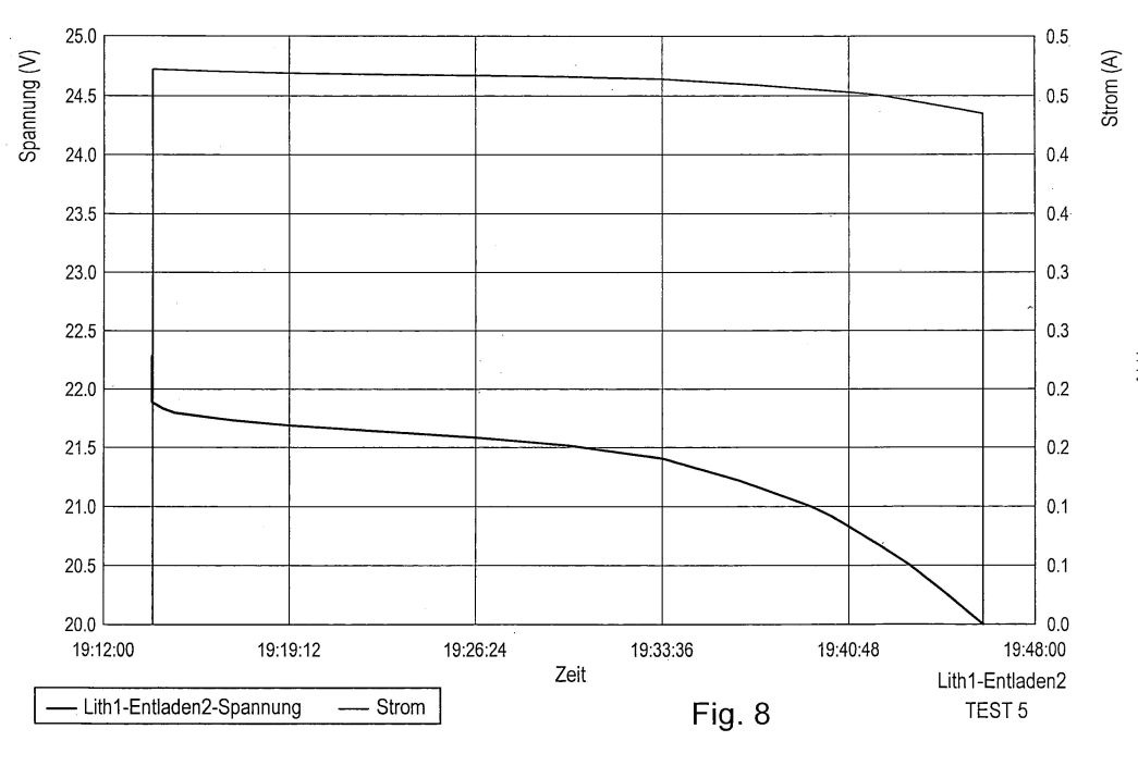
Fig. 9 -- Stromund potential gradient with test No. 6;

Fig. 10 -- Stromund FR annungs process with test No. 7;

Fig. 11 -- Stromund tension process with test No. 8.

The figs Ia to IC show an exploded view (Fig. Ia), a cross section (Fig. Ib) of the ion cell array according to invention as well as a plan view on the used Manetstreifen 1.
A commercial lithium ion Akku 2, here of the type SAMSUNG SF US 18650 GR with a rated voltage of 3,7 V becomes equipped with two magnetic stripes 1. The magnetic stripes of the type 3M 300LSE, permanent magnet volume MGO 1317 Piastinorm are on the length of the Akkus 2 cut and itself diametric opposite parallel to longitudinal axis of the Akkus on the Akkumantel mounted. Like Fig. IC shows, exhibits themselves the magnetic stripes 1 an alternate polarity, itself parallel in each case to the longitudinal extension of the magnetic stripe extended. The used Akku does not exhibit protection circuit.
As in Fig. Ib shown cross section shows becomes the Akku 2 together with the magnetic stripes 1 from a dielectric film 3 coated, is mounted on which in accordance with an embodiment of the present invention an aluminium foil, which wraps the barrel of the Akkus complete.
The lithium ionAkku shown here is wound, a similar Elko capacitor. There it when rolling up to varying thickness of the electrolyte layer which is between the electrodes to possibly come can do is more conceivable it that each attachment place does not show the same effect on the barrel for the magnetic stripes. It became observed that the attachment of a magnetic stripe on the Akku leads to a slight voltage increase at the lithium ionAkku. This voltage increase was however somewhat different with the accomplished experiments with some lithium IonenAkkus depending upon attachment place of the magnetic stripe.
Fig. an experimental setup with that the optimum attachment place of the magnetic stripe found shows 2 became. In addition a lab power supply unit with variable internal resistance and separate adjustable voltage became as well as limitable current to the poles of the LithiumIonen Akkus connected and so set that an additional ammeter no current flow shown integrated into the circle. That is, the voltage provided of the lab power supply unit corresponded to the accurate output voltage of the lithium ion Akkus. Subsequent one became magnetic stripe on the hydraulic cylinder barrel-flat of the Akkus arranged and on this circular shifted. With the fact shown itself that by the approach of the magnetic stripe already at the Akku a somewhat higher output voltage has set and over the Ampermeter 6 a small current from a Milliamper into the power supply unit back-flowed itself. When circular shifting the magnetic stripe shown itself that each radial position of the magnetic stripe does not lead to the same return flow stream. The magnetic stripe was finally left at the location on the barrel of the Akkus, at which the current flowing back into the power supply unit was largest. Subsequent one became a second magnetic stripe on the diametric opposite side of the barrel of the Akkus mounted. By this measure, as in the following will be still closer to discuss, the efficiency knew erf [iota] ndungsgemässen apparatus the generation of electrical energy other increased to become.
In the following an experiment described, with which a series circuit by six like standing above described prepared lithium ion Akkus first were subjected to a conditioning, in the following the more near explained was employed and subsequent Ladeund of unloading attempts with this structure and with a series circuit of six identical, commercial lithium ionAkkus compared.
The conditioning of an apparatus according to invention to the generation of electrical energy the ion cells equipped contained in it with magnetic stripes become and/or. the single ion cell in an initial step on their nominal capacity loaded. This can take place after a conventional method, like initially described. Subsequent ones become the ion cells and/or. becomes the ion cell shorted over a short period, in which still no noticeable heating of the cell arises. It turned out that this period should not exceed five seconds, the preferably made shortcircuit over two seconds. A strong heating of the ion cell, i.e. over more than few degrees C< 0>, is to be avoided absolutely, since this points on irreversible destruction processes within the cell.
A in this way conditioned ion cell, in particular a lithium ion accumulator shows already a higher efficiency, i.e. Ladungsund energy output increased opposite a conventional not conditioned ion cell. This effect can become other increased, if the subsequent conditioning steps follow after short circuit. An other charge with a charging current between 10 mA upto max. follows. to 400 mA to at the poles of the cell a voltage lies close, which is appropriate for about 10% over the rated voltage of the cell and which charging current sank on bottom 10 mA. Subsequent one becomes the ion cell with a current of 80 mA upto max. 600 mA controlled discharged, until abrupt Spannungsund becomes discharge current waste observed. Subsequent one becomes the charging operation repeated and the ion cell again controlled discharged described above, until an accelerated voltage drop becomes observed.
Such a conditioning became at lithium ionAkkus made of the type SAMSUNG SF US 18650 GR, whereby the charge with a charging current of 80 mA made, until against the poles a voltage of 4 V rested to the cell (rated voltage of the cell 3.7 V) and the charging current on 10 mA had sunk. Then the lithium ion cell with a current of 160 mA discharged to the voltage at the poles of the cell had dropped to 2,5 V. After renewed loading, like described above, the lithium ion cell up to a voltage of 2,95 V became discharged.
Six such lithium ion Akkus, after the described above method conditioned, became connected in series. Each Akku was here with reference to Fig. and bottom interposing of an insulative film with an aluminium foil coated provide 1 described with two magnetic stripes.
Comparison purposes a series circuit became from six commercial lithium ion Akkus of same type of building created. This set lithium ion Akkus is designated in the following LITH 1, whereas the modified and conditioned set LITH 2 is designated.
In the following [alpha] [lambdas] Kkusätzen implemented measurements iesen on transacted experts for EMV in its spaces, sworn in ordered, of Industrieund Chamber of Commerce region Stuttgart of public and.
Fig. a summary of the Messergebriisse shows 3. The figs 4 to 10 show the single received in each case measuring curves Spannungsund of current process.
In test No. 1 and test No. 2 became the Akkusätze LITH 1 and LITH 2 discharged in each case to at its poles a voltage of 20 V lay close. The rated voltage of the used Akkus amounts to after manufacturer data in each case 3.7 V. A series circuit of 6 Akkus results in thus a rated voltage of the arrangement of 22,2 V. Like Fig. 5 had the Akkusatz LITH 1 at the beginning of the discharge process a voltage of 22,58 V shows whereas the Akkusatz LITH 2 a significant higher initial tension of 24,03 V exhibited. The removed charge quantity, with the discharged one up to a relaxation of 20 V results in each case and the corresponding energy is for the two Akkusätze in the table in Fig. 3 shown. One recognizes already that the modified Akkusatz LITH 2 a substantial higher charge quantity removed became, i.e. 464 mAh opposite 264 mAh with LITH 1.
Subsequent ones were again loaded the Akkusätze LITH 1 and LITH 2 in the tests 3 and 4. The output voltage before that loadings of LITH 1 was about 20,46 V, which adjust themselves after the removal of the load after the discharged one automatically. LITH 1 as well as LITH 2 became over one time interval of approximately 39 min. continuous with a current of 400 mA charged, whereby at the end of the charging operation with LITH 1 a conclusion tension of 22,8 V adjusted itself. Within this period the Akkusatz LITH 1 electrical energy in height of 5,69 Wh became supplied. With LITH 2 output the voltage, which adjusts itself automatically, lay already with 22,8 V. During about 39 min. continuous continuous shop became LITH 2 electrical energy in the height of 4,24 Wh supplied, whereby the conclusion tension was with 23,68 V.
Subsequent ones became the Akkusätze LITH 1 and LITH 2 in the tests No. 5 and 6 again up to an unloading conclusion tension of 20 V discharged. The output voltage of LITH 1 was about 22, 27 V and the corresponding output voltage of LITH 2 with 22, 18 V. Up to the unloading conclusion tension of 20 V LITH became 1 electrical energy in height of 5,24 Wh and LITH 2 electrical energy in height of 4,64 Wh removed.
At these measurements it is remarkable that removed with the modified Akkusatz LITH 2 a significant higher charge quantity (438.6 mAh) became than with the Akkusatz LITH 1 (245.3 mAh). Also the removed electrical energy is larger in height of 4,67 Wh with the discharged one of LITH 2 around more as 10% than with loadings supplied electrical energy in height of 4,24 Wh.
In the tests 7 and 8 became in a renewed charging operation on the basis of an output voltage of 21,47 V with LITH 1 and 22.49 V with LITH 2 again electric charge and thus electrical energy supplied. The power supply amounted to 4.05 Wh with LITH 1 and 4, 26 Wh with LITH 2.
With renewed discharged one (test 9 and 10) tapping energy was with the Akkusatz LITH 1 with 3,84 Wh and with the Akkusatz LITH 2 with 4,44 Wh.
Also with this test a positive energy balance (charged 4.26 Wh, discharged 4.44 Wh) results for LITH 2, whereas the Akkusatz LITH 1 “normal” behaved (charged 4.05 Wh, discharged 3.84 Wh).
It can recapitulatory be stated that with repeated made Ladeund discharge processes with modified the according to invention lithium ionAkkusätzen, which were equipped with magnetic stripes and became on the type conditioned described above a significant better tapping energy balance adjusts itself that, than this adjusted same type, as they became used with the modified Akkusätzen, with conventional lithium ionAkkus.
On which the efficiency increase of the modified lithium ionAkkus in the long run is not based is at present complete clarified. It stands to assume that the magnetic fields set on the lithium ionAkkus have an influence on the Interkalationsprozess within electrolytes of the Akkus. With increased incorporation of lithium ions into the host lattice electrolytes shows this system increased ferromagnetic interactions, which by the magnetic field affected put on from the outside to become to be able.
It becomes suspected that the particular conditioning with permanent magnets can lead provided lithium ionAkkus to an increase of the mobility of the lithium ions, so that the effects arising by the magnetic interactions become amplified.
DE
102009024430
Charging current signal for charging e.g. lithium-ion battery utilized as power source for generating voltage in electric car, has inductively measurable current intensity greater than Joule's heat in conductor of current component
Charging current signal for charging e.g. lithium-ion battery utilized as power source for generating voltage in electric car, has inductively measurable current intensity greater than Joule's heat in conductor of current component
Abstract -- The signal has inductively measurable current intensity greater than Joule's heat in a conductor of a current component, where the current intensity is measured by a gripper ammeter. The Joule's heat in the conductor is measured by a hot wire measuring element, where the signal is generated by ion cells i.e. lithium-ion-accumulators, that are provided in a static magnetic field. Permanent magnets or electromagnets generate the magnetic field at location of the ion cells. An independent claim is also included for a device for generating a charging current signal.
[0001] The present invention concerns a charging current signal for loading galvanic elements and electrolytic capacitors as well as an apparatus to the generation of such a charging current signal.
[0002] Galvanic elements are energy converters, which produce a voltage on electrochemical path. If this process is reversible, one speaks of accumulators (secondary batteries). An electrolytic capacitor is a poled capacitor, whose anode electrode consists of a metal, on which by electrolysis (anodic oxidation, formation) a non conductive insulating layer generated becomes, which forms the dielectric of the capacitor. The electrolyte (z. B. an electrical conductive liquid) is the cathode of the electrolytic capacitor.
[0003] Accumulators and capacitors is common that they can be loaded with an electric charge, whereby between its electrodes a voltage develops itself, and a current removed can become, until the potential difference between the electrodes falls below a specific threshold value.
[0004] Loadings of a galvanic element, for example a lithium ion accumulator and to loadings of an electrolytic capacitor relatively much time takes in claim. Thus for example the utility is limited of lithium ion accumulators as current source in electric road vehicles strong, since these after reaching its unloading condition over several hours, for example over night, with a charger again to be loaded to have. Also the prolonged loading time of electrolytic capacitors limits their use, for example as rapid accessible charge packed memory, which should be more removable in short time intervals charge.
[0005] The present invention is the basis the object to indicate a charging current signal with which galvanic elements and electrolytic capacitors are more chargeable within very much short time with very much high efficiency.
[0006] Furthermore the present invention the object is the basis to indicate an apparatus to the generation of such a charging current signal.
[0007] This object becomes 7 dissolved with the features of the claims 1 and. In the Unteransprüchen features prefered embodiments of the present invention are characterized.
[0008] The German patent application 10 2008 53 407,2-45 of 27. October 2008 describes among other things an apparatus to the generation of electrical energy, which exhibits at least a lithium ion accumulator as well as means to the generation of a static magnetic field to locations at least of the lithium ion accumulator.
[0009] The inventor of the present invention has the observation made with the use of the apparatus described in the patent application specified above that also from such an apparatus generated current of galvanic elements, like lead nickel accumulators or such a thing, and electrolytic capacitors in very much short time and with one much high efficiency to be loaded to be able. On the search for the cause for this significant more favourable load behavior found became that the so prepared charging current has other properties than for example a comparable charging current generated by a normal lab power supply unit.
[0010] In particular found became that with the observed very short charging times from the apparatus specified above to the generation of electrical energy into the galvanic element or into the electrolytic capacitor a current with a so large current intensity (approximately calculated between 30 and 50 A) would have had to flow, which would have let melt the used lead wires or to warm up at least noticeably have. This was even not however the case, not if as connecting cable a stripped telephone wire with a cross-section area of less than 1 mm< of 2> used became. This could be touched during the charging operation without more worth, which for a minimum heating on a temperature below 30 [deg.]C speaks.
[0011] While a current flows by an electrical conductor, the electrons drifting by the electrical conductor experience an inner frictional force, which is the same electrical force and is this opposite. The electrical energy becomes by those the electrical force opposite same large inner frictional force in warm one converted. This warm one one calls the Joule warm one or currentwarm. It is it, those the conductor with high current heated. The heating of an electrical conductor accompanies with its thermal expansion, which one makes oneself with hot wire instrument movements the measurement of current intensities. A correlation becomes prepared between the linear extension of an hot wire with the current flow and the current intensity by the hot wire of the flowing stream. A simple constructed hot wire instrument movement consists of a wire biased with a tension spring, which is partial wound around a movable stored shaft, at which a pointer mounted is. If the hot wire expands due to its heating by by it the flowing stream, then the tension spring catches this prolonged enlargement and the shaft with the pointer turns. Such Hitz one can calibrate wire work, by one the z. B. additional current with various currents, measured with a digital measuring instrument, and various pointer positions on a scale labeled.
[0012] Such an hot wire instrument movement can do thus calibrated will and can by an electrical conductor the flowing stream precise indicate. Another type to measure by an electrical conductor the flowing stream evaluates arising magnetic field to the measurement stromata its around the conductor. DC can become with clip current ammeters, which exhibit a current sensor, measured. These clip current ammeters exhibit a opening by hinges ferrite or iron bundle of laminations handle and the current sensors work after the compensation principle (backing-off current transducer) or the Hall effect (Hall sensor) or with magnetic field-dependent resistors as well as an electrical transducer.
[0013] With a measurement of the current intensity from the described above apparatus to the generation of electrical energy to a galvanic element or an electrolytic capacitor of the flowing stream the subsequent observation became made: If the current with a hot wire instrument movement becomes measured, then this indicates a significant smaller current intensity than a simultaneous used current pliers measuring instrument.
[0014] As counter proof a commercial lab power supply unit with limitable Stromabgabe became used the charge of a galvanic element or a Elktrolytkondensators. Here measured by the connecting conductor between lab power supply unit and galvanic element or electrolytic capacitor the flowing stream became likewise on the one hand with the hot wire instrument movement and on the other hand with the clip current ammeter.
[0015] Here shown both metres always in the frame of the measurement accuracy of same values on.
[0016] The current delivered from the described above apparatus to the generation of electrical energy in the following charging current signal mentioned becomes. This charging current signal a generated magnetic field around the electrical conductor, by which it flows, which corresponds to a current intensity, which is larger as the current intensity measured with the hot wire instrument movement.
[0017] The current intensity measured with the hot wire instrument movement stands in conformity with the observation that itself also a thin lead wire with loadings of the galvanic element or the electrolytic capacitor not substantial heated. If one adjusts the lab power supply unit to a delivery stream, which corresponds to the current intensity, which became displayed with the use of the described above apparatus the generation of electrical energy of the hot wire instrument movement, and used one the lab power supply unit as current source, then no substantial heating of the thin lead wire shows up also here.
[0018] If one adjusts on the other hand the lab power supply unit to a Stromabgabe, which corresponds to the current intensity, which became displayed with the use of the described above apparatus the generation of electrical energy by the clip current ammeter, then this leads inevitably to a glowing and subsequent melts of the thin lead wire.
[0019] One proceeds from the assumption that the hot wire instrument movement actual by the connecting line between the described above apparatus to the generation electrical energy and the galvanic element and/or. indicates to the electrolytic capacitor, what in accordance with the observation stands that also thin lead wires warm up only insignificantly, then means this the fact that this so generated, charging current signal according to invention leads to it that around the electrical conductor, by which the charging current signal flows a magnetic field generated becomes, which corresponds to a significant higher current intensity. The causes for this effect are so far unerklärt.
[0020] It means on the other hand that introduced during a charging operation with the charging current signal according to invention into the galvanic element which can be loaded or the electrolytic capacitor a certain charge quantity of an external power source does not become into the galvanic element or into the electrolytic capacitor, which can become this then after trigger of warm losses again removed. Rather the effected charging current signal according to invention in the galvanic element or the electrolytic capacitor there a separation of load, which is not correlated with that Joule warm ones in a conductor producing current portion of the charging current signal, but with the field strength of the magnetic field generated of the charging current signal.
[0021] It concerns here thus obviously not around a ledigliche transmission of a charge quantity in a certain time of an external power source on a galvanic element or an electrolytic capacitor, but the initiation of a separation of load within a galvanic element or an electrolytic capacitor by the charging current signal according to invention. If one refers the charge state achieved in the galvanic element or the electrolytic capacitor after a predetermined time on, the Joule warm ones producing current portion of the charging current signal measured with the hot wire instrument movement, then this results in one much high efficiency, which does not pour from a simple charge transfer of external current into the galvanic element or the electrolytic capacitor understood can become. The charging current signal according to invention activates rather within a galvanic element or an electrolytic capacitor a separation of load.
[0022] Test series, according to invention became charged with which galvanic elements and electrolytic capacitors with the charging current signal, to have result in that beyond that the charging current signal according to invention the charging operation opposite a charge with conventional chargers and/or. Current sources significant shortened.
CH 701244
Charging current signal for charging galvanic element and electrolytic capacitors, has current part generating Joule heat in conductor, where Joule heat is measured with hot wire measuring element
Charging current signal for charging galvanic element and electrolytic capacitors, has current part generating Joule heat in conductor, where Joule heat is measured with hot wire measuring element
Abstract -- The charging current signal has a current part generating the Joule heat in a conductor, where the Joule heat is measured with a hot wire measuring element. The inductively measurable current is measured with a clamp ammeter. The charging current signal is generated by an ion cell located in a magnetic field. The ion cell is a lithium-ion-accumulator.

[0001] The present invention concerns a charging current signal for loading galvanic elements and electrolytic capacitors as well as an apparatus to the generation of such a charging current signal.
[0002] Galvanic elements are energy converters, which produce a voltage on electrochemical path. If this process is reversible, one speaks of accumulators (secondary batteries). An electrolytic capacitor is a poled capacitor, whose anode electrode consists of a metal, on which by electrolysis (anodic oxidation, formation) a non conductive insulating layer generated becomes, which forms the dielectric of the capacitor. The electrolyte (e.g. an electrical conductive liquid) is the cathode of the electrolytic capacitor.
[0003] Accumulators and capacitors is common that they can be loaded with an electric charge, whereby between its electrodes a voltage develops itself, and a current removed can become, until the potential difference between the electrodes falls below a specific threshold value.
[0004] Loadings of a galvanic element, for example a Lithiunr of ion accumulator and to loadings of an electrolytic capacitor relatively much time takes in claim. Thus for example the utility is limited of lithium ion accumulators as current source in electric road vehicles strong, since these after reaching its unloading condition over several hours, for example over night, with a charger again to be loaded to have. Also the prolonged loading time of electrolytic capacitors limits their use, for example as rapid accessible charge packed memory, which should be more removable in short time intervals charge.
[0005] The present invention is the basis the object to indicate a charging current signal with which galvanic elements and electrolytic capacitors are more chargeable within very much short time with very much high efficiency.
[0006] Furthermore the present invention the object is the basis to indicate an apparatus to the generation of such a charging current signal.
[0007] This object becomes 7 dissolved with the features of the claims 1 and. In the Unteransprüchen features prefered embodiments of the present invention are characterized.
[0008] The German patent application 10 2008 053 407,2-45 of 27. October 2008 describes among other things an apparatus to the generation of electrical energy, which exhibits at least a lithium ion accumulator as well as means to the generation of a static magnetic field to locations at least of the lithium ion accumulator.
[0009] The inventor of the present invention has the observation made with the use of the apparatus described in the patent application specified above that also from such an apparatus generated current of galvanic elements, like lead nickel accumulators or such a thing, and electrolytic capacitors in very much short time and with one much high efficiency to be loaded to be able. On the search for the cause for this significant more favourable load behavior found became that the so prepared charging current has other properties than for example a comparable charging current generated by a normal lab power supply unit.
[0010] In particular found became that with the observed very short charging times from the apparatus specified above to the generation of electrical energy into the galvanic element or into the electrolytic capacitor a current with a so large current intensity (approximately calculated between 30 and 50 A) would have had to flow, which would have let melt the used lead wires or to warm up at least noticeably have. This was even not however the case, not if became used as connecting cables a stripped telephone wire with a cross-section area of less than 1 mm2. This could be touched during the charging operation easily, which for a minimum heating on a temperature below 30 [deg.]C speaks.
[0011] While a current flows by an electrical conductor, the electrons drifting by the electrical conductor experience an inner frictional force, which is the same electrical force and is this opposite. The electrical energy becomes by those the electrical force opposite same large inner frictional force in warm one converted. This warm one one calls the Joule warm one or currentwarm. It is it, those the conductor with high current heated. The heating of an electrical conductor accompanies with its thermal expansion, which one makes oneself with hot wire instrument movements the measurement of current intensities. A correlation becomes prepared between the linear extension of an hot wire with the current flow and the current intensity by the hot wire of the flowing stream. A simple constructed hot wire instrument movement consists of a wire biased with a tension spring, which is partial wound around a movable stored shaft, at which a pointer mounted is. If the hot wire expands due to its heating by by it the flowing stream, then the tension spring catches this prolonged enlargement and the shaft with the pointer turns. One can calibrate such a hot wire work, by one e.g. additional current with various currents, measured with a digital measuring instrument, and various pointer positions on a scale labeled.
[0012] Such an hot wire instrument movement can do thus calibrated will and can by an electrical conductor the flowing stream precise indicate. Another type to measure by an electrical conductor the flowing stream evaluates arising magnetic field to the measurement stromata its around the conductor. DC can become with clip current ammeters, which exhibit a current sensor, measured. These clip current ammeters exhibit a opening by hinges ferrite or iron bundle of laminations handle and the current sensors work after the compensation principle (backing-off current transducer) or the Hall effect (Hall sensor) or with magnetic field-dependent resistors as well as an electrical transducer.
[0013] With a measurement of the current intensity from the described above apparatus to the generation of electrical energy to a galvanic element or an electrolytic capacitor of the flowing stream the subsequent observation became made: If the current with a hot wire instrument movement becomes measured, then this indicates a significant smaller current intensity than a simultaneous used current pliers measuring instrument.
[0014] As counter proof a commercial lab power supply unit with limitable Stromabgabe became used the charge of a galvanic element or an electrolytic capacitor. Here measured by the connecting conductor between lab power supply unit and galvanic element or electrolytic capacitor the flowing stream became likewise on the one hand with the hot wire instrument movement and on the other hand with the clip current ammeter.
[0015] Here shown both metres always in the frame of the measurement accuracy of same values on.
[0016] The current delivered from the described above apparatus to the generation of electrical energy in the following charging current signal mentioned becomes. This charging current signal a generated magnetic field around the electrical conductor, by which it flows, which corresponds to a current intensity, which is larger as the current intensity measured with the hot wire instrument movement.
[0017] The current intensity measured with the hot wire instrument movement stands in conformity with the observation that itself also a thin lead wire with loadings of the galvanic element or the electrolytic capacitor not substantial heated. If one adjusts the lab power supply unit to a delivery stream, which corresponds to the current intensity, which became displayed with the use of the described above apparatus the generation of electrical energy of the hot wire instrument movement, and used one the lab power supply unit as current source, then no substantial heating of the thin lead wire shows up also here.
[0018] If one adjusts on the other hand the lab power supply unit to a Stromabgabe, which corresponds to the current intensity, which became displayed with the use of the described above apparatus the generation of electrical energy by the clip current ammeter, then this leads inevitably to a glowing and subsequent melts of the thin lead wire.
[0019] One proceeds from the assumption that the hot wire instrument movement actual by the connecting line between the described above apparatus to the generation electrical energy and the galvanic element and/or. indicates to the electrolytic capacitor, what in accordance with the observation stands that also thin lead wires warm up only insignificantly, then means this the fact that this so generated, charging current signal according to invention leads to it that around the electrical conductor, by which the charging current signal flows a magnetic field generated becomes, which corresponds to a significant higher current intensity. The causes for this effect are so far unerklärt.
[0020] It means on the other hand that introduced during a charging operation with the charging current signal according to invention into the galvanic element which can be loaded or the electrolytic capacitor a certain charge quantity of an external power source does not become into the galvanic element or into the electrolytic capacitor, which can become this then after trigger of warm losses again removed.
[0021] Rather the effected charging current signal according to invention in the galvanic element or the electrolytic capacitor there a separation of load, which is not correlated with that Joule warm ones in a conductor producing current portion of the charging current signal, but with the field strength of the magnetic field generated of the charging current signal.
[0022] It concerns here thus obviously not around a ledigliche transmission of a charge quantity in a certain time of an external power source on a galvanic element or an electrolytic capacitor, but the initiation of a separation of load within a galvanic element or an electrolytic capacitor by the charging current signal according to invention. If one refers the charge state achieved in the galvanic element or the electrolytic capacitor after a predetermined time on, the Joule warm ones producing current portion of the charging current signal measured with the hot wire instrument movement, then this results in one much high efficiency, which cannot become from a simple charge transfer of an external power source understood into the galvanic element or the electrolytic capacitor. The charging current signal according to invention activates rather within a galvanic element or an electrolytic capacitor a separation of load.
[0023] Test series, according to invention became charged with which galvanic elements and electrolytic capacitors with the charging current signal, to have result in that beyond that the charging current signal according to invention the charging operation opposite a charge with conventional chargers and/or. Current sources significant shortened.
http://www.overunity.com/index.php?topic=10466
Overunity.com Forum
Jörg
Raimund Hempel and his Ionic Magnetic Power IMP CAP
Charging
hartiberlin
Stefan Hartmann, Moderator of overunity.com forum
Re: Jörg Raimund Hempel and his Ionic Magnetic Power IMP CAP Charging
« Reply #4 on: March 04, 2011, 06:37:20 AM »
...The main thing is, that he uses a magnet field around flat Li-accumulators (extracted from cell phone batteries, without the charging security circuit in them) to "polarize" them somehow. If you then draw current from them, this current charges up electrolytic caps and lead acid batteries very fast.
He made another test, where a few Li-accumulators in series this way charged up a discharged 12 Volts lead acid battery up to a full charge up to 14 Volts in very fast 20 minutes or so. The lead acid battery then had full capacity.
The Li-accumulators were not much discharged afterwards.
So if anybody want to try this, just take 4 Li-accumulators from a cell phone and put them in series and put a few magnets around them and charge them up when the magnets still stick to them. This seems to polarize them. Then when the Li-accumulators are fully charged, put them all in series and charge a discharged 12 Volts lead acid battery with it, but don´t put any ampmeter between it, as this prevents the fast charging.
Or just repeat the test that is shown in the german video.
There he also has 2 discharged lead acid batteries in parallel with the Li-accumulators inside the magnet array. the 2 batteries at the top wrapped in the alufoil probably don´t have any effect, maybe he just only made it this way to not give too much away from the basic effect. They also seem not to be connected, as he only has one copper band there and not 2 contacts... But when you read the patents it gets clearer.
There are also other patents out there that use magnets wrapped around Li-accumulators to enhance their charging capacity.
But the main effect is the the fast charging without Joule heating of the electrolyte capacitor. This way, if supercaps can be used, an electric could be recharged very fast and economical !
Maybe the Tesla Roadster then won´t need anymore any expensive battery pack, but just a stack of 2700 Farad supercaps will do, which also will be recharged in just a few minutes instead of hours ! And it does not need much energy from your grid outlet also !
Regards, Stefan.
Quote from: hakware on March 04, 2011, 06:53:26 AM
Coler converter of sorts.. very interesting.
No, just some kind of polarisation stuff for Li-Ion or Li-Polymer batteries that changes the behaviour of the charging current... Maybe it freezes just one axis of the electron movement or changes the electron or Ion spins, so the charging current does not have any real ohmic losses when it is applied to the capacitor ? Maybe then massive currents can flow without the Joule heating in small diameter wires ? Maybe some kind of room temperature supra-conductor effect through magnetic polarisation ? Who knows, must be researched..
Regards, Stefan.
Maybe not but I see a relation between the magnets and current flow through the magnetic field as seen in the patent papers. Its very coler-ish. regardless of whatever magic mechanism is going on with the batteries.
Re: Jörg Raimund Hempel and his Ionic Magnetic Power IMP CAP Charging
« Reply #8 on: March 04, 2011, 07:01:53 PM »
It would appear you have to strip out the IC regulator from the lithium pack. Most cellphone batteries and laptop lithium have on board charge control.
Be VERY careful if you puncture a lithium battery bag it will explode violentlywith a gush of FIRE!!
Now i tried one today it was a 3.7v nokia battery it was very dead. It measured 0v.
So i cut open the pack and inside is the lithium bag. Don't puncture it or melt it with a soldering iron or you will be in a world of shit!
Coming from the edge is two foil strips one i managed to solder a wire on it which is hard not to get any heat near the battery bag. The other one was broken short so close i dare not risk an iron close to it so i just managed to hook a croc clip on it. It measure 2.9v wo the regulator IC was disconnecting it as they are supposed to below 3 volts. I spent about 15 mins swiping a few neo magnets all over it, front back etc and connected up 2 off 100,000Uf caps so 200,000uf in total. The voltage went up to 3 volts on the caps and shorting it made a good crack on the screwdriver.
I can not reproduce the results in the patent with what i have here i also wound 250 turns of magnet wire around it and zapped it several times with a 12v battery. Again i did not notice any effect of extra volts or anything unusual on the caps. I don't have any magnetic strip stuff. If you are going to do this i strongly suggest you buy Radio Control LiPO packs as they do not have any battery electronics and its safer easier to get to the raw lipo cells. The RC lipo helicopter cells cost only about $1.50 each.
Most of the magnet strip you can find on Ebay have a north pole strip and south pole strip. They name them A and B strips which attract to each other for door closers etc. Now i do not know if these strips are the same polarity as discussed in the patent but there are hundreds of suppliers of all the same A and B magnet strips on Ebay.
BTW most bare lithium ion cells are charged to 4.2 volts (never more than that for safety and longevity of the battery) and will run at 3.6 volts or so under load. Try to never let them go below 2.8 volts or they will suffer damage and shortened life. bolt, hope you didn't breathe any burning lithium cell fumes as that stuff is really bad. I'm on another forum where lithium batteries are discussed all the time and they've got some real battery experts there. They have occasional explosions with these as they are largely used in sealed devices. Most problems happen from cell reverse charging when you have multiple cells in series or from overcharging and too fast discharging.
e2matrix
Sr. Member
Re: Jörg Raimund Hempel and his Ionic Magnetic Power IMP CAP Charging
Reply #11 on: March 04, 2011, 08:39:36 PM »
One thing I find of concern. He says he completely discarged the Li-ion cells to zero. For one you should never do that both because it's dangerous and because it's damaging to the cells. Li-ion cells are nothing like NiMH or NiCd cells. From reading the info it almost sounds like he thinks they are the same or similar in use as NiMH. Running a Li-ion completely to zero is very hard on the cells but they will self recover quite a bit of voltage if it only is done a couple times. Just mentioning this but that is not to say it is a hole in his idea - just a concern as I was reading this.
e2Matrix
Quote:
Running a Li-ion completely to zero is very hard on the cells but they will self recover quite a bit of voltage if it only is done a couple times. Just mentioning this but that is not to say it is a hole in his idea - just a concern as I was reading this.
Sir you are absolutely correct,This is a humungous no no with lithium batteries!
Surely he knows this! perhaps a prerequisite conditioning of sorts ,to attain the "Effect"?
2matrix
Sr. Member
Reply #14 on: March 04, 2011, 09:09:25 PM »
Chet, Yes I hope if anyone is trying this that they realize how explosive these cells can be under a dead short. It doesn't always happen but I've seen enough pictures of the damage from them to know people here need to be aware of it. I'll try first without that step of shorting but might sacrifice a couple if it doesn't work without that. For anyone trying this I'd suggest heavy fireproof box outside with protective gear like face shield and heavy gloves etc. Preferable to short and then stand back a distance.
One thing I haven't figured out yet is whether it makes a difference whether the N or S is near the positive of the battery. It looks like the drawing shows the North pole by the positive battery pole if he is using standard battery schematic convention.