Philip
M. KANAREV
Pulse Motor
Pulse Motor
PESWikiNews
http://www.youtube.com/watch?v=kSLfrh-CFYQ
F. M. KANAREV : Self-Rotating Generator
RU PATENT # 2399144 : INERTIAL ELECTROMECHANICAL PULSE SOURCE OF POWER SUPPLY [ PDF ]
RU PATENT # 2340996 : INERTIAL ELECTROMECHANICAL PULSE SOURCE OF POWER SUPPLY [ PDF ]
PATENTS
F.M. KANAREV : Self-Rotating Generator (Google Translation)
F.M.
KANAREV : Pulse Power [ ZIP.DOC
]
F.M. KANAREV : The Law of the Electric Circuit [ ZIP.DOC ]
F.M. KANAREV : On The Way to Pulse Power Engineering [ ZIP.DOC ]

http://pesn.com/2010/10/13/9501712_Kanarev_announces_self-running_motor-generator/
Oct. 13, 2010
On Sept. 12 Professor Philip Mihailovich Kanarev sent me a video by email saying: "It seems to me this VIDEO will be interesting to you and to the readers of your site."
Dear Mr. Sterling D. Allan,
If you have a translator speaking Russian, almost all information which interests you can be found at the following addresses: (www.akademik.su).
http://kubsau.ru/science/prof.php?kanarev
http://www.sciteclibrary.ru/rus/avtors/k.html
I made the experiments only to check my theory of a microcosm. The new theory of a microcosm has prompted me to see if could make a self-rotating generator. It is made and works. Prospects and areas of its application have no borders. It will be the basic source of future ecologically pure power. Under the theory of a microcosm, I spend the first scientific seminar in a month [in Krasnodar on 25-27 November 2010]. It will be broadcast on the Internet in Russian and English languages. All information on the seminar can be found at http://www.akademik.su.
I have sent you video about the first motor-generator. I have asked one of academicians of the Russian Academy of Sciences to head the commission on test of our generator. Such tests have already passed. In the report results of tests are written down. The first-ever motor - the generator makes energy more than consumes from a network. By the end of the year the second generator will be tested. The accumulator [capacitor] will be a source of its input. The second generator will feed an electrolyzer and simultaneously charge the accumulator. Term of its service will be equal to accumulator service life, that is it will work about five years and will use only energy of the accumulator.
Best regards,
D. T. S. Prof. Kanarev
Professor Philip Mihailovich Kanarev sent me a video by email saying: "It seems to me this VIDEO will be interesting to you and to the readers of your site."
"You see the world's first self-rotating electric generator. The rotor performs the function of a motor; and the stator performs the function of a generator. [??] can be fed from a socket, but it can be fed from an accumulator [capacitor]. The stator generates two working electrical impulses. One of them is used for the technological[?] electrolysis. The second feeds the bulb, but [it can] also be used to charge the accumulator. As a result, an[?] eternal[?] source of energy is being formed with a life span equal to the life span of [the] accumulator."
Generators of electricity - a long-standing invention of mankind. They are the main source of electrical energy. To ensure that they generate electricity, need her primary source, whose role is most often carries water or water vapor. There are generators that are driven by electric motors, energy consumption from the mains. In this case, as usual, the electric motor rotates the generator rotor and stator produces electrical energy. The old laws of electrodynamics prohibit the existence of a generator rotor that would include the power grid, and drew up to the stator electrical energy or vice versa, the stator would include the power grid, and drew up the rotor to electrical energy. New laws of electrodynamics, by contrast, show how to do such a generator, and it was made (Photo). Terms of Reference for its production, we developed proved to be surprisingly simple, and it was successfully implemented talented Russian engineer Sergei Zatsarininym.
A two-month test the world's first self-rotating generator of electric pulses showed that such a generator is the future. In this case, energy consumption for idle self-rotating generator of electrical pulses are reduced to almost zero, and increased moment of inertia of the rotor can easily overcome the mechanical resistance and a small short-term magnetic resistance. As a result of energy generated in the stator, is determined not by the energy supplied from an external power source, and the kinetic energy of the rotor, which he receives in the process of starting to work. Subsequently, its value is supported by short pulses of the primary power source, which leads to the fact that amount of energy output is greater than the amount of energy consumed! In addition, first used the principle of energy recovery pulse inhibit rotation of the rotor, to power the generator. While stable fixed 5-fold increase at 2000 rpm. At high speeds recorded a 10-fold excess, but a small moment of inertia of the rotor does not allow us long-term (more than 10 minutes) to keep such a regime. The first sample of self-rotating generator generates pulses of current to 120 A and the second, which is already under construction, will generate pulses of up to 200 A with a pulse, close to zero and the rotor speed from 3000 to 5000 rpm. This will be a generator to power the electrolysis.
Another feature of the self-rotating generator of electrical pulses, which is now called "motor-generator(MG) - complexity of multi-use. For example, a motor-generator designed to power the electrolyzer, will not be able to exercise their functions on the drive the car instead of gasoline engine. As a result, the problem of developing generators for specific purposes. But, as the experience gained, it is solvable and has an open road for domestic power units (5-10kW), to supply which is enough battery power. In this case, the generator will automatically recharge the battery. Battery power would also be sufficient for the power block, propelling the car.
He has been testing his theory of microcosm and has developed a generator that is self running and generates free electricity. Fascinating and a much welcome proof of concept for this type of technology.
"You see the world's first self-rotating electric generator.
"The rotor performs the function of a motor; and the stator performs the function of a generator.
"[[ At present it is ]] fed from a socket, but it can be fed from an accumulator [capacitor].
"The stator generates two working electrical impulses.
One of them is used for the technological [[ process ]].
The second feeds the bulb, but also [[ can ]] be used to charge the accumulator.
http://scitizen.com/nanoscience/nano-capacitors-the-root-towards-the-super-power-battery_a-5-2918.html
Everything is Holographic Intelligence On Hierarchic Dimensional Levels !
Here is a new fractal-based "spin-glass" model of the Cosmos which incorporates the attributes of a fifth primary field and the Langrange points described in superstring theory with the harmonic resonances contained in the ancient Hindu text known as the Rig Veda. It is taken as given that at the baseline, everything in the known universe can be viewed as, and indeed is comprised of, information.
Information is conveyed in the Torsion Field at a rate which is at least 109 times the speed of light. This revelation, which is largely due to the ground breaking work of Russian scientist V.A. Dubrovsky up to 1985, has now been confirmed by at least six other laboratories in the former Soviet States. Based on the ground breaking work of V.A. Ablekov, David Bohm and Karl Pribram it has been determined that the Torsion Field is holographic.
Since all known substances possess a non-zero collective spin state, then all substances must also create and exist within their own localized Torsion Fields. We now know that the expanse and frequency structure of any substance is determined by its chemical composition and the expanse structure of its molecules or crystalline lattice.
"Unlike electromagnetism, where analogous charges repel and opposite charges attract, in torsion fields similar charges attract and opposite charges repulse. As the Torsion Field is generated by a classical spin, Torsion Field emissions are non-dissipative and are not attenuated by the interposition of mass or the effects of distance. Torsion Fields cannot be screened by any known materials or combination of materials or fields.
At the Institute for Problems of Materials Science in Kiev, scientists have for more than 25 years used torsion field generators as an essential part of the manufacture of exceedingly exotic materials for which we have no comparable products in the West. In addition to providing a fascinating insight into the way consciousness may operate at the level of vicinal water in the human brain, a clear understanding of these mechanics could enable us to create energy storage devices which demonstrate energy conversion characteristics well in excess of gasoline [650 watt hours/kilo]41. At the Institute for Problems of Materials Science, Trefilov, Tovschuk and Kovalyuk have created a solid state energy cell [energy accumulator] which produces 850-1040 watt hours/kilo, in laboratory models. The reliability of their claims regarding this technology have been verified by INEL, DARPA and the ATML. A key element of their construction method relies on the effects of a torsion field beam which operates during the process of crystalline lattice deposition42. IPMS has also perfected the use of a torsion field device which enables them to manufacture mono-molecular powders of strategic metals which can be stored in conventional glass containers without voluntarily generating static electricity.
Abstract -- FIELD: electricity. ^ SUBSTANCE: proposed source of power supply consists of vessel with electric motor, on shaft of which there is rotor installed with permanent magnets of various polarity, magnetic conductor with winding rigidly connected to vessel, and current collector in the form of magnetic conductor winding outputs differing by the fact that vessel comprises cover and oppositely installed thrust bearings for electric motor shaft, one of them is arranged on vessel cover, and the other one - on opposite wall of vessel. At the same time on shaft between wall of vessel and electric motor there is block of unbalance gears installed, having central gear and additional gears with unbalances. Electric motor, block of unbalanced gears and rotor of electromechanical generator of electric pulses have single rotation shaft. Magnetic conductor interacting with permanent magnets on inner surface of rotor rigidly connected to cover and fixed, which facilitates removal of electric potential from winding of magnetic conductor. Combination of mechanical torque pulses generator with electromechanical generator of pulses on single shaft reduces load on shaft of electric motor. ^ EFFECT: reduced costs of electric energy.
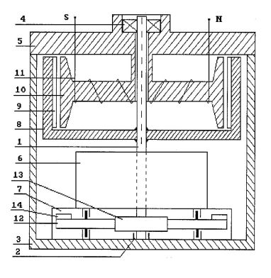
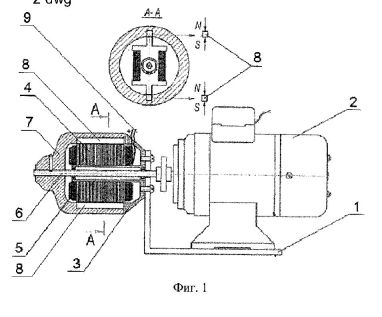
Abstract: Invention is related to the field of electrical engineering ande physical and chemcial technologies, and refers to devices used for water electrolysis. Substance of invnetion consists in the fact that in pulses electromechanical source of supply that contains casing (1), stator (3) in the form of magnetic core (4) with winding (5), rotor (7) and current collector (9), according to the invention, in casing (1) electric motor (2) is installed (2) on the shaft (6) of which rotor (7) is installed with permanent magnets (8), which are isntalled along magnetic core (4) of windings (5) of stator (3), which is rigidly fixed to casing (1) at that permanent magnets (8) are installed opposite to each other with the possibility of magnetic power lines penetration through windings (5) of stator (3), at that internal surfaces of permanetn magnets (8) have dissimilar poles, and as current collector windings (5) of stator (3) are used. Effect: Reduction of power inputs for water electrolysis.

METHOD AND DEVICE FOR PRODUCING AND USING HEAT
RU2303206
Heat Generator
US2009263113 (A1) - 2009-10-22
DEVICE FOR PRODUCTION OF OXYGEN AND HYDROGEN
RU2004103020
DEVICE FOR PRODUCTION OF HEAT ENERGY, HYDROGEN AND OXYGEN
RU2284370
APPARATUS FOR PRODUCING HEAT POWER, HYDROGEN AND OXYGEN
RU2003135737 (A) - 2005-05-20
DEVICE FOR PRODUCTION OF THERMAL ENERGY, HYDROGEN AND OXYGEN
RU2258098
DEVICE FOR PRODUCTION OF THERMAL ENERGY, HYDROGEN AND OXYGEN
RU2003135142
DEVICE FOR PRODUCTION OF THE HEAT ENERGY, HYDROGEN AND OXYGEN
RU2003133344
APPARATUS FOR PRODUCING HEAT ENERGY, HYDROGEN, AND OXYGEN
RU2003132719
APPARATUS FOR PRODUCING HEAT POWER, HYDROGEN AND OXYGEN
RU2256006
DEVICE FOR PRODUCING HEAT ENERGY, HYDROGEN, AND OXYGEN
RU2228390
ELECTROLYTIC CELL OF LOW-AMPERE ELECTROLYZER FOR PRODUCTION OF HYDROGEN AND OXYGEN FROM WATER
RU2227817
DEVICE FOR PRODUCTION OF HYDROGEN AND OXYGEN
RU2232829
FACILITY FOR GENERATION OF GAS MIXTURE AND TRANSMUTATION OF NUCLEI OF ATOMS OF CHEMICAL ELEMENTS
RU2210630
CATHODE FOR PLASMOELECTROLYTIC REACTOR
RU2186153
HEAT ENERGY, HYDROGEN AND OXYGEN PRODUCING APPARATUS
RU2213162
APPARATUS FOR PRODUCING ELECTRICAL AND HEAT ENERGY, HYDROGEN, AND OXYGEN
RU2177512
APPARATUS FOR PRODUCING HEAT ENERGY, HYDROGEN AND OXYGEN
RU2175027
GEAR TO GENERATE THERMAL ENERGY, HYDROGEN AND OXYGEN
RU2167958
GEAR TO GENERATE THERMAL ENERGY OF HYDROGEN AND OXYGEN
RU2157427
APPARATUS TO GENERATE THERMAL ENERGY AND STEAM AND GAS MIXTURE
RU2157862
DEVICE FOR PRODUCTION OF HEAT ENERGY, HYDROGEN AND OXYGEN
RU2157861
http://Kanarev.innoplaza.net
INTRODUCTION
There is an American scientist among the laureates of the first Russian prize “Global Energy” of the year of 2003. He was awarded the prize, because (as it was informed) he managed in his laboratory to form an electric pulse, which power is equal to power of all power stations of the world. Let us show that a mistake during the pulse power calculation is a result of this experiment. For this purpose, let us analyze energetics of pulses of voltage, current and power being obtained by us while determining electric energy consumed by the cell of water electric generator of heat [1].
ANALYSIS
The oscillograms of pulses of voltage, current and power being obtained with the help of PCS500A oscilloscope are given in Figs 1, 2 and 3. Horizontal scale is 50 μs per division. [1].
Fig. 1. Voltage pulse
Fig 2. Current pulse
Fig. 3. Power pulse
It is clearly seen (Figs 1, 2 and 3) that a form of pulses of voltage, current and power can be reduced to a rectangular form. Pulse duration will be equal to 0.00007 s, pulse repetition period is 0.00725 s, pulse frequency is =1000/7.25=137.9. Duty ratio is equal to S=0.00725/0.00007 =103.6. If the pulse form is considered to be a rectangular one, duty factor will be equal to Z=1/103.6=0.0096. Voltage pulse amplitude is =300 V, current pulse amplitude is =50 A and power pulse amplitude is =300х50= 15 kW. Taking it into consideration, average voltage value will be = 300х0.0096=2.88 V, average current value will be =
50х0.0096=0.48 A, average power value will be =15000х0.0096=144 W.
Let us put a question: has power pulse (Fig. 3) 15 kW actually, and is average value of pulse power equal to 144 W? Is the calculation carried out correctly? [1]
In accordance with Si-system, if one voltage pulse with amplitude of and with assigned duration is supplied per second and one current pulse with amplitude of and with duration, the above-mentioned values of voltage and current can be used for power calculation only in the case when their duration corresponds to one second. Such requirement originates from the power unit definition by Watt. Watt is work done per second by current and voltage continuously.
Consequently, pulse action of voltage and current should be prolonged till one second. Naturally, an oblong rectangle is obtained instead of a pulse in this case. Height of this rectangle multiplied by a pulse form factor (=1 if the pulse form is reduced to a rectangular form and =0.5 if the pulse form is reduced to a triangular form), and it will be an average value of voltage if voltage pulse is spread, an average value of current if current pulse is spread, and an average value of power if power pulse is spread.
If not one, but several pulses are generated during one second, the above-mentioned average values of pulses of voltage, current and power, as it is considered now, should be multiplied by frequency of pulse. This operation is equivalent to a division of amplitude values of voltage , current and power by duty ratio . If we take into account that , average values of voltage and current will be equal to:
(1)
(2)
If we pay attention to the formulas (1) and (2), we’ll see that the amplitude values of voltage and current are reduced to a duration of one second; that’s why their values are in strict correspondence with Si-system. It is a vivid example of the fact that average power of the pulse should be determined according to the formulas:
(3)
(4)
But this result is considered to be erroneous, because voltage and current are changed simultaneously and synchronously, and their duty ratios are united in one duty ratio in power pulse; that’s why, as it is considered now, average pulse power should be determined according to the formula [3], [4]
(5)
This value of average power will be obtained if we use the formula
(6)
Later on, we’ll prove experimentally that power pulse (Fig. 3) has not 15000 W and 144.80 W, but only 1.40 W. That’s why a question emerges: where does the essence of the mistake lie?
A single division by duty ratio of a product of the amplitude values of voltage and current (formula 5) is equivalent to stretching till duration of one second of power pulse. It appears from this that either voltage pulse, or current pulse (i.e. one of two pulses) is stretched to duration of one second in the formula (5). This process can be shown graphically (Fig. 4) if it is supposed that the experiment has lasted 300 s.
Fig. 4. Diagram of duration of maximal (300 V, 50A) and average (3.0 V, 0.5A) values of voltage and current
Average values of voltage of 2.88≈3.0 V and current 0,48 ≈0.50 A have been obtained in consequence of division of their maximal values of 300 V and 50 A by duty ratio of 103.6 ≈100. If we divide only voltage V by duty ratio, and we’ll not divide current A, it will mean that current value during 300 s with average voltage value of 3.0 V will be equal to 50 A (Fig. 4, b). It is a vivid contradiction, which results in the mistake in the formulas (5 and 6).
As two values (voltage and current) are changed, it is necessary to determine average power during pulse consumption of energy according to the formulas (3 and 4). The formulas (5 and 6) take into account a change of one value, which forms power, voltage or current. That’s why they should give an incorrect result. How can it be checked?
It is necessary to carry out such an experiment where not the electronic pulse generator connected with the whole grid galvanically has been used, but a rotating magnetic generator, like a magnetic inductor. Power pulses being generated by the magnetic inductor and sent to the consumer will be on the same shaft of the magnetic inductor and the electric motor, which rotates the magnetic inductor. Galvanic coupling between the general grid and the grid of the magnetic inductor is absent in this case. Electric energy of pulses of the magnetic inductor is converted into mechanical energy of the jointly rotating shafts of the magnetic inductor and the electric motor.
As the electric motor is connected in the general grid, an electric motor will show in general the energy being consumed by the electric motor, the magnetic inductor and the consumer connected to the grid of the magnetic inductor. If we write energy consumption by the electric motor, the magnetic inductor and the consumer and subtract electric energy consumption of the electric motor and the magnetic inductor from the obtained value, we’ll get energy being generated by the magnetic inductor and consumed by the consumer [5], [6].
Thus, as we have the readings of the electric energy meter and the pulses of voltage and current being written with the help of the oscilloscope, we can see, which formula (3 and 4) or (5 and 6) is correct and which one is erroneous. A diagram of such experiment is shown in Fig. 5. An oscillogram of pulses of voltage and current is shown in Fig. 6.
The cell of the water electric generator of heat has been used as a consumer of electric energy generated by the magnetic inductor (Fig. 7).
Fig, 5. Electrical diagram of the system: 1 - cell; 2 - electric motor; 3 - magnetic inductor; 4 - the coupling connecting the motor shaft with the generator shaft; 5 - electric meter; 6- Nektronix TDS 2014 oscilloscope
Fig. 6. Sample of an oscillogram of voltage and current being generated by the magnetic inductor
Fig. 7. Photo and diagram of the cell of the water electric generator of heat (patent No. 2258098)
Voltage pulses were rectified and corrected; the magnetic inductor was driven with the help of a single-phase electric motor from the grid (Fig. 5). In order to determine energy consumed by the electric motor, a domestic electric meter was used. The readings of the electric meter 5 were duplicated by the readings of voltmeter and ammeter being arranged before the cell 1 as well as by the readings of the oscilloscope 6 (Fig. 5). Heated solution energy was determined in a standard way.
The experimental results are given in Table 1. Here is power consumed by the cell from the mains. It is equal to a difference between the readings of the electric power meter when the load (the cell) is energized and de-energized. is heat power of the heated solution. is power being indicated by the voltmeter and the ammeter arranged before the cell. is power being indicated by the oscilloscope and determined according to the formula (10). is power indicated by the oscilloscope and determined according to the formula (11). is an index of efficiency of the solution heating process.
Table 1. Indices of the direct experiment
Experiment No., W, W, W, W, W1 2 3 4 56 71 9.40 3.10 4.32 3.8017.10 3.102 9.80 3.53 4.45 3.4115.35 2.773 10.20 3.10 4.40 4.3019.35 3.344 11.30 4.80 5.10 4.8021.60 2.355 13.28 4.00 5.00 5.3023.85 3.32
We managed to adjust the magnetic inductor in such a way that it generated voltage pulses; its average amplitude was equal to . Average amplitude of current pulse was equal to. Pulse duration was . Pulse frequency was= 255.8 Hz. Pulse duty ratio was . It is natural that such pulse form is easily reduced to a triangular form; then, . As a result, the formulas (1) and (2) give such average values of voltage and current.
(7)(8)
A calculation according to the formulas (3 and 4) gives a result , which is close (9 and 10) to the readings of the meter (Table 1, experience 2) and the readings of voltmeter and ammeter (Fig. 5).
(9)(10)
Then according to formula (5), average power will be equal to (Table 1, experiment 2)
(11)
It is an explicitly wrong result, because the electric power meter has shown that in this case the cell has consumed =3.53 W (Table 1, experience 2).
When we compare the calculation results according to the formulas (10 and 11) with the experimental results (Table 1, experiment 2), we see that when determining average power according to the oscillogram the amplitude values of voltage and current should be divided by duty ratio not once (11) as it is stipulated in the manuals [3], [4], but twice (10) as it is shown in the formulas (4 and 10). Only this power value will agree with the reality. It appears from this that the formulas (3, 4, 9 and 10) are correct and the formulas (5, 6 and 11) are erroneous.
Thus, the power pulse shown in Fig. 3 has not 15 kW and not 144.8 W, but only.
Let us see what the results are when motor 2 and magnetic inductor 3 (Fig. 5) are replaced by the electronic pulse generator (Figs 8, 9). The oscillograms of the experiment are shown in Figs 1, 2 and 3.
As it is shown in Fig. 1, an average amplitude of voltage pulses is 300 V when an average value of voltage is 3.0 V (Fig. 9); an average amplitude of current pulses (Fig. 2) was 50 A when an average value current is 0.5 A (Fig. 9). Pulse duration is =0,00007 when duty ratio is =100 and duty factor is = 0.01.
Fig. 8. Electrical diagram of the system: 1 - cell: 2- electronic pulse generator; 5 - electric power meter; 6- PCS500A oscilloscope
Fig. 9. Block diagram of electric value measurement: 1 - cell; 2 – PCS500A electronic oscilloscope; 3 - pulse generator
In accordance with the readings of voltmeter , ammeter and oscilloscope (Figs 8, 9), power at the input into the cell of water electric generator of heat is =3.0х0.5=1.50 W on average. A calculation according to the formulas (3 and 4) gives a near result of 1.40 W.
A question arises: what power will be indicated by the instruments: voltmeter and ammeter arranged before the pulse generator (Figs 8 and 9)? It is quite natural that the voltmeter will indicate mains voltage = 220 V, current value is increased as well, because there are two loads before ammeter : cell 1 and electronic pulse generator 3. =0.65 A is in our experiment (Fig. 9). As a result, power implemented by pulse generator 3 and cell 1 is =220х0.65=143 W; it is at variance with the result (=1.4 W) being obtained according to the formulas (3 and 4). Their correctness has been proved by us experimentally.
Let us pay attention to the fact that the obtained result is =143 W. It is near to the result =144.8 being obtained during the calculation according to the incorrect formulas (5 and 6).
Now we know that actual energy consumed by the cell is indicated by the instruments (voltmeter , ammeter) arranged before it. The oscilloscope readings will correspond to actual consumption of energy by the cell if the formulas (3 and 4) are used. The formulas (5 and 6) distort a result in proportion to pulse duty ratio. When pulse duty ratio is equal 100, the formulas (5 and 6) increase an actual power consumption by the cell nearly 100fold. Such are the properties of electric circuits with the electronic pulse generator. It does not implement evident energy efficiency of the cell. Energy efficiency of the cell is implemented only in the case when energy source, which is similar to magnetic inductor, is used (Table 1) [5], [6].
Thus, we have eliminated the contradictions between the instrument readings and the calculations during pulse consumption of electric power. Now let us put such a question: according to what formula has the laureate of the prize “Global Energy” calculated pulse power? An answer is clear: according to the formula
(12)
which (as it is supposed in modern physics) determines instantaneous power of a pulse and which (as we have already shown) is a fictitious value.
As power of one pulse is given in the formula (12), it is quite natural that and can have very large values. But in any case, their product gives the fictitious value, not the actual value. If we take pulse duty ratio, which has been used in our experiments () and keep in mind that in order to get actual pulse power the right part of the formula (12) should be divided by a square of duty ratio (in the case being considered by ), actual power of pulse is 10000fold less than the value, for which the prize was awarded. If we take into account the fact that pulse duration being obtained by the laureate was considerably less than the one being obtained during our experiment and duty ratio was considerably greater than 100, the actual value of the power pulse will be millionfold less than the value, for which the prize was awarded.
CONCLUSION
Let us put the representatives of the committee “Global energy” at their ease. Their mistake is nothing as compared with the mistakes made by the Nobel prize [7].
REFERENCES
1. Ph.M. Kanarev. The Foundations of Physchemistry of the Microworld. the 6th edition. Krasnodar, 2005. 500 pages
2. L.A. Bessonov. Theoretical Elements of Electrical Engineering. Manual. “Vyshaya shkola”, M.,1973. 750 pages
3. Yu.A. Brammer, I.N. Pashchuk. Pulse and Digital devices. Manual. “Vyshaya shkola”, M., 2002.
4. Yu.I. Yefremov. Elements of Pulse Engineering. Study guide for the institutions of higher learning. M., “Vyshaya shkola”, 1979. 528 pages
5. Ph.M. Kanarev. On the Way to Pulse Power Engineering. http://Kanarev.innoplaza.net. Article 57.
6. Ph.M. Kanarev. The Law of Electric Circuit. http://Kanarev.innoplaza.net. Article 58.
7. Ph.M. Kanarev. History of Scientific Search and its Results. http://Kanarev.innoplaza.net. Articles 60 and 61.
http://www.youtube.com/watch?v=kSLfrh-CFYQ
F. M. KANAREV : Self-Rotating Generator
RU PATENT # 2399144 : INERTIAL ELECTROMECHANICAL PULSE SOURCE OF POWER SUPPLY [ PDF ]
RU PATENT # 2340996 : INERTIAL ELECTROMECHANICAL PULSE SOURCE OF POWER SUPPLY [ PDF ]
PATENTS
F.M. KANAREV : Self-Rotating Generator (Google Translation)
F.M. KANAREV : The Law of the Electric Circuit [ ZIP.DOC ]
F.M. KANAREV : On The Way to Pulse Power Engineering [ ZIP.DOC ]
http://pesn.com/2010/10/13/9501712_Kanarev_announces_self-running_motor-generator/
Oct. 13, 2010
Kanarev
Announces a Self-Running Motor-Generator
Russian Professor Ph. M. Kanarev presents what he calls "the world's first self-rotating electric generator," saying it has been tested by a scientist from the Russian Academy of Science. The device was built to demonstrate Kanarev's theory of the mocrocosmos.
by
Sterling D. Allan
Pure Energy Systems News
On Sept. 12 Professor Philip Mihailovich Kanarev sent me a video by email saying: "It seems to me this VIDEO will be interesting to you and to the readers of your site."
Dear Mr. Sterling D. Allan,
If you have a translator speaking Russian, almost all information which interests you can be found at the following addresses: (www.akademik.su).
http://kubsau.ru/science/prof.php?kanarev
http://www.sciteclibrary.ru/rus/avtors/k.html
I made the experiments only to check my theory of a microcosm. The new theory of a microcosm has prompted me to see if could make a self-rotating generator. It is made and works. Prospects and areas of its application have no borders. It will be the basic source of future ecologically pure power. Under the theory of a microcosm, I spend the first scientific seminar in a month [in Krasnodar on 25-27 November 2010]. It will be broadcast on the Internet in Russian and English languages. All information on the seminar can be found at http://www.akademik.su.
I have sent you video about the first motor-generator. I have asked one of academicians of the Russian Academy of Sciences to head the commission on test of our generator. Such tests have already passed. In the report results of tests are written down. The first-ever motor - the generator makes energy more than consumes from a network. By the end of the year the second generator will be tested. The accumulator [capacitor] will be a source of its input. The second generator will feed an electrolyzer and simultaneously charge the accumulator. Term of its service will be equal to accumulator service life, that is it will work about five years and will use only energy of the accumulator.
Best regards,
D. T. S. Prof. Kanarev
Professor Philip Mihailovich Kanarev sent me a video by email saying: "It seems to me this VIDEO will be interesting to you and to the readers of your site."
"You see the world's first self-rotating electric generator. The rotor performs the function of a motor; and the stator performs the function of a generator. [??] can be fed from a socket, but it can be fed from an accumulator [capacitor]. The stator generates two working electrical impulses. One of them is used for the technological[?] electrolysis. The second feeds the bulb, but [it can] also be used to charge the accumulator. As a result, an[?] eternal[?] source of energy is being formed with a life span equal to the life span of [the] accumulator."
Self-Rotating
Generator
Kanarev FM
Kanarev FM
Generators of electricity - a long-standing invention of mankind. They are the main source of electrical energy. To ensure that they generate electricity, need her primary source, whose role is most often carries water or water vapor. There are generators that are driven by electric motors, energy consumption from the mains. In this case, as usual, the electric motor rotates the generator rotor and stator produces electrical energy. The old laws of electrodynamics prohibit the existence of a generator rotor that would include the power grid, and drew up to the stator electrical energy or vice versa, the stator would include the power grid, and drew up the rotor to electrical energy. New laws of electrodynamics, by contrast, show how to do such a generator, and it was made (Photo). Terms of Reference for its production, we developed proved to be surprisingly simple, and it was successfully implemented talented Russian engineer Sergei Zatsarininym.
A two-month test the world's first self-rotating generator of electric pulses showed that such a generator is the future. In this case, energy consumption for idle self-rotating generator of electrical pulses are reduced to almost zero, and increased moment of inertia of the rotor can easily overcome the mechanical resistance and a small short-term magnetic resistance. As a result of energy generated in the stator, is determined not by the energy supplied from an external power source, and the kinetic energy of the rotor, which he receives in the process of starting to work. Subsequently, its value is supported by short pulses of the primary power source, which leads to the fact that amount of energy output is greater than the amount of energy consumed! In addition, first used the principle of energy recovery pulse inhibit rotation of the rotor, to power the generator. While stable fixed 5-fold increase at 2000 rpm. At high speeds recorded a 10-fold excess, but a small moment of inertia of the rotor does not allow us long-term (more than 10 minutes) to keep such a regime. The first sample of self-rotating generator generates pulses of current to 120 A and the second, which is already under construction, will generate pulses of up to 200 A with a pulse, close to zero and the rotor speed from 3000 to 5000 rpm. This will be a generator to power the electrolysis.
Another feature of the self-rotating generator of electrical pulses, which is now called "motor-generator(MG) - complexity of multi-use. For example, a motor-generator designed to power the electrolyzer, will not be able to exercise their functions on the drive the car instead of gasoline engine. As a result, the problem of developing generators for specific purposes. But, as the experience gained, it is solvable and has an open road for domestic power units (5-10kW), to supply which is enough battery power. In this case, the generator will automatically recharge the battery. Battery power would also be sufficient for the power block, propelling the car.
He has been testing his theory of microcosm and has developed a generator that is self running and generates free electricity. Fascinating and a much welcome proof of concept for this type of technology.
"You see the world's first self-rotating electric generator.
"The rotor performs the function of a motor; and the stator performs the function of a generator.
"[[ At present it is ]] fed from a socket, but it can be fed from an accumulator [capacitor].
"The stator generates two working electrical impulses.
One of them is used for the technological [[ process ]].
The second feeds the bulb, but also [[ can ]] be used to charge the accumulator.
http://scitizen.com/nanoscience/nano-capacitors-the-root-towards-the-super-power-battery_a-5-2918.html
Everything is Holographic Intelligence On Hierarchic Dimensional Levels !
Here is a new fractal-based "spin-glass" model of the Cosmos which incorporates the attributes of a fifth primary field and the Langrange points described in superstring theory with the harmonic resonances contained in the ancient Hindu text known as the Rig Veda. It is taken as given that at the baseline, everything in the known universe can be viewed as, and indeed is comprised of, information.
Information is conveyed in the Torsion Field at a rate which is at least 109 times the speed of light. This revelation, which is largely due to the ground breaking work of Russian scientist V.A. Dubrovsky up to 1985, has now been confirmed by at least six other laboratories in the former Soviet States. Based on the ground breaking work of V.A. Ablekov, David Bohm and Karl Pribram it has been determined that the Torsion Field is holographic.
Since all known substances possess a non-zero collective spin state, then all substances must also create and exist within their own localized Torsion Fields. We now know that the expanse and frequency structure of any substance is determined by its chemical composition and the expanse structure of its molecules or crystalline lattice.
"Unlike electromagnetism, where analogous charges repel and opposite charges attract, in torsion fields similar charges attract and opposite charges repulse. As the Torsion Field is generated by a classical spin, Torsion Field emissions are non-dissipative and are not attenuated by the interposition of mass or the effects of distance. Torsion Fields cannot be screened by any known materials or combination of materials or fields.
At the Institute for Problems of Materials Science in Kiev, scientists have for more than 25 years used torsion field generators as an essential part of the manufacture of exceedingly exotic materials for which we have no comparable products in the West. In addition to providing a fascinating insight into the way consciousness may operate at the level of vicinal water in the human brain, a clear understanding of these mechanics could enable us to create energy storage devices which demonstrate energy conversion characteristics well in excess of gasoline [650 watt hours/kilo]41. At the Institute for Problems of Materials Science, Trefilov, Tovschuk and Kovalyuk have created a solid state energy cell [energy accumulator] which produces 850-1040 watt hours/kilo, in laboratory models. The reliability of their claims regarding this technology have been verified by INEL, DARPA and the ATML. A key element of their construction method relies on the effects of a torsion field beam which operates during the process of crystalline lattice deposition42. IPMS has also perfected the use of a torsion field device which enables them to manufacture mono-molecular powders of strategic metals which can be stored in conventional glass containers without voluntarily generating static electricity.
Abstract -- FIELD: electricity. ^ SUBSTANCE: proposed source of power supply consists of vessel with electric motor, on shaft of which there is rotor installed with permanent magnets of various polarity, magnetic conductor with winding rigidly connected to vessel, and current collector in the form of magnetic conductor winding outputs differing by the fact that vessel comprises cover and oppositely installed thrust bearings for electric motor shaft, one of them is arranged on vessel cover, and the other one - on opposite wall of vessel. At the same time on shaft between wall of vessel and electric motor there is block of unbalance gears installed, having central gear and additional gears with unbalances. Electric motor, block of unbalanced gears and rotor of electromechanical generator of electric pulses have single rotation shaft. Magnetic conductor interacting with permanent magnets on inner surface of rotor rigidly connected to cover and fixed, which facilitates removal of electric potential from winding of magnetic conductor. Combination of mechanical torque pulses generator with electromechanical generator of pulses on single shaft reduces load on shaft of electric motor. ^ EFFECT: reduced costs of electric energy.
Abstract: Invention is related to the field of electrical engineering ande physical and chemcial technologies, and refers to devices used for water electrolysis. Substance of invnetion consists in the fact that in pulses electromechanical source of supply that contains casing (1), stator (3) in the form of magnetic core (4) with winding (5), rotor (7) and current collector (9), according to the invention, in casing (1) electric motor (2) is installed (2) on the shaft (6) of which rotor (7) is installed with permanent magnets (8), which are isntalled along magnetic core (4) of windings (5) of stator (3), which is rigidly fixed to casing (1) at that permanent magnets (8) are installed opposite to each other with the possibility of magnetic power lines penetration through windings (5) of stator (3), at that internal surfaces of permanetn magnets (8) have dissimilar poles, and as current collector windings (5) of stator (3) are used. Effect: Reduction of power inputs for water electrolysis.
OTHER
PATENTS
METHOD AND DEVICE FOR PRODUCING AND USING HEAT
RU2303206
Heat Generator
US2009263113 (A1) - 2009-10-22
DEVICE FOR PRODUCTION OF OXYGEN AND HYDROGEN
RU2004103020
DEVICE FOR PRODUCTION OF HEAT ENERGY, HYDROGEN AND OXYGEN
RU2284370
APPARATUS FOR PRODUCING HEAT POWER, HYDROGEN AND OXYGEN
RU2003135737 (A) - 2005-05-20
DEVICE FOR PRODUCTION OF THERMAL ENERGY, HYDROGEN AND OXYGEN
RU2258098
DEVICE FOR PRODUCTION OF THERMAL ENERGY, HYDROGEN AND OXYGEN
RU2003135142
DEVICE FOR PRODUCTION OF THE HEAT ENERGY, HYDROGEN AND OXYGEN
RU2003133344
APPARATUS FOR PRODUCING HEAT ENERGY, HYDROGEN, AND OXYGEN
RU2003132719
APPARATUS FOR PRODUCING HEAT POWER, HYDROGEN AND OXYGEN
RU2256006
DEVICE FOR PRODUCING HEAT ENERGY, HYDROGEN, AND OXYGEN
RU2228390
ELECTROLYTIC CELL OF LOW-AMPERE ELECTROLYZER FOR PRODUCTION OF HYDROGEN AND OXYGEN FROM WATER
RU2227817
DEVICE FOR PRODUCTION OF HYDROGEN AND OXYGEN
RU2232829
FACILITY FOR GENERATION OF GAS MIXTURE AND TRANSMUTATION OF NUCLEI OF ATOMS OF CHEMICAL ELEMENTS
RU2210630
CATHODE FOR PLASMOELECTROLYTIC REACTOR
RU2186153
HEAT ENERGY, HYDROGEN AND OXYGEN PRODUCING APPARATUS
RU2213162
APPARATUS FOR PRODUCING ELECTRICAL AND HEAT ENERGY, HYDROGEN, AND OXYGEN
RU2177512
APPARATUS FOR PRODUCING HEAT ENERGY, HYDROGEN AND OXYGEN
RU2175027
GEAR TO GENERATE THERMAL ENERGY, HYDROGEN AND OXYGEN
RU2167958
GEAR TO GENERATE THERMAL ENERGY OF HYDROGEN AND OXYGEN
RU2157427
APPARATUS TO GENERATE THERMAL ENERGY AND STEAM AND GAS MIXTURE
RU2157862
DEVICE FOR PRODUCTION OF HEAT ENERGY, HYDROGEN AND OXYGEN
RU2157861
http://Kanarev.innoplaza.net
PULSE
POWER
Ph. M. Kanarev
E-mail: kanphil@mail.ruPh. M. Kanarev
INTRODUCTION
There is an American scientist among the laureates of the first Russian prize “Global Energy” of the year of 2003. He was awarded the prize, because (as it was informed) he managed in his laboratory to form an electric pulse, which power is equal to power of all power stations of the world. Let us show that a mistake during the pulse power calculation is a result of this experiment. For this purpose, let us analyze energetics of pulses of voltage, current and power being obtained by us while determining electric energy consumed by the cell of water electric generator of heat [1].
ANALYSIS
The oscillograms of pulses of voltage, current and power being obtained with the help of PCS500A oscilloscope are given in Figs 1, 2 and 3. Horizontal scale is 50 μs per division. [1].
Fig. 1. Voltage pulse
Fig 2. Current pulse
Fig. 3. Power pulse
It is clearly seen (Figs 1, 2 and 3) that a form of pulses of voltage, current and power can be reduced to a rectangular form. Pulse duration will be equal to 0.00007 s, pulse repetition period is 0.00725 s, pulse frequency is =1000/7.25=137.9. Duty ratio is equal to S=0.00725/0.00007 =103.6. If the pulse form is considered to be a rectangular one, duty factor will be equal to Z=1/103.6=0.0096. Voltage pulse amplitude is =300 V, current pulse amplitude is =50 A and power pulse amplitude is =300х50= 15 kW. Taking it into consideration, average voltage value will be = 300х0.0096=2.88 V, average current value will be =
50х0.0096=0.48 A, average power value will be =15000х0.0096=144 W.
Let us put a question: has power pulse (Fig. 3) 15 kW actually, and is average value of pulse power equal to 144 W? Is the calculation carried out correctly? [1]
In accordance with Si-system, if one voltage pulse with amplitude of and with assigned duration is supplied per second and one current pulse with amplitude of and with duration, the above-mentioned values of voltage and current can be used for power calculation only in the case when their duration corresponds to one second. Such requirement originates from the power unit definition by Watt. Watt is work done per second by current and voltage continuously.
Consequently, pulse action of voltage and current should be prolonged till one second. Naturally, an oblong rectangle is obtained instead of a pulse in this case. Height of this rectangle multiplied by a pulse form factor (=1 if the pulse form is reduced to a rectangular form and =0.5 if the pulse form is reduced to a triangular form), and it will be an average value of voltage if voltage pulse is spread, an average value of current if current pulse is spread, and an average value of power if power pulse is spread.
If not one, but several pulses are generated during one second, the above-mentioned average values of pulses of voltage, current and power, as it is considered now, should be multiplied by frequency of pulse. This operation is equivalent to a division of amplitude values of voltage , current and power by duty ratio . If we take into account that , average values of voltage and current will be equal to:
(1)
(2)
If we pay attention to the formulas (1) and (2), we’ll see that the amplitude values of voltage and current are reduced to a duration of one second; that’s why their values are in strict correspondence with Si-system. It is a vivid example of the fact that average power of the pulse should be determined according to the formulas:
(3)
(4)
But this result is considered to be erroneous, because voltage and current are changed simultaneously and synchronously, and their duty ratios are united in one duty ratio in power pulse; that’s why, as it is considered now, average pulse power should be determined according to the formula [3], [4]
(5)
This value of average power will be obtained if we use the formula
(6)
Later on, we’ll prove experimentally that power pulse (Fig. 3) has not 15000 W and 144.80 W, but only 1.40 W. That’s why a question emerges: where does the essence of the mistake lie?
A single division by duty ratio of a product of the amplitude values of voltage and current (formula 5) is equivalent to stretching till duration of one second of power pulse. It appears from this that either voltage pulse, or current pulse (i.e. one of two pulses) is stretched to duration of one second in the formula (5). This process can be shown graphically (Fig. 4) if it is supposed that the experiment has lasted 300 s.
Fig. 4. Diagram of duration of maximal (300 V, 50A) and average (3.0 V, 0.5A) values of voltage and current
Average values of voltage of 2.88≈3.0 V and current 0,48 ≈0.50 A have been obtained in consequence of division of their maximal values of 300 V and 50 A by duty ratio of 103.6 ≈100. If we divide only voltage V by duty ratio, and we’ll not divide current A, it will mean that current value during 300 s with average voltage value of 3.0 V will be equal to 50 A (Fig. 4, b). It is a vivid contradiction, which results in the mistake in the formulas (5 and 6).
As two values (voltage and current) are changed, it is necessary to determine average power during pulse consumption of energy according to the formulas (3 and 4). The formulas (5 and 6) take into account a change of one value, which forms power, voltage or current. That’s why they should give an incorrect result. How can it be checked?
It is necessary to carry out such an experiment where not the electronic pulse generator connected with the whole grid galvanically has been used, but a rotating magnetic generator, like a magnetic inductor. Power pulses being generated by the magnetic inductor and sent to the consumer will be on the same shaft of the magnetic inductor and the electric motor, which rotates the magnetic inductor. Galvanic coupling between the general grid and the grid of the magnetic inductor is absent in this case. Electric energy of pulses of the magnetic inductor is converted into mechanical energy of the jointly rotating shafts of the magnetic inductor and the electric motor.
As the electric motor is connected in the general grid, an electric motor will show in general the energy being consumed by the electric motor, the magnetic inductor and the consumer connected to the grid of the magnetic inductor. If we write energy consumption by the electric motor, the magnetic inductor and the consumer and subtract electric energy consumption of the electric motor and the magnetic inductor from the obtained value, we’ll get energy being generated by the magnetic inductor and consumed by the consumer [5], [6].
Thus, as we have the readings of the electric energy meter and the pulses of voltage and current being written with the help of the oscilloscope, we can see, which formula (3 and 4) or (5 and 6) is correct and which one is erroneous. A diagram of such experiment is shown in Fig. 5. An oscillogram of pulses of voltage and current is shown in Fig. 6.
The cell of the water electric generator of heat has been used as a consumer of electric energy generated by the magnetic inductor (Fig. 7).
Fig, 5. Electrical diagram of the system: 1 - cell; 2 - electric motor; 3 - magnetic inductor; 4 - the coupling connecting the motor shaft with the generator shaft; 5 - electric meter; 6- Nektronix TDS 2014 oscilloscope
Fig. 6. Sample of an oscillogram of voltage and current being generated by the magnetic inductor
Fig. 7. Photo and diagram of the cell of the water electric generator of heat (patent No. 2258098)
Voltage pulses were rectified and corrected; the magnetic inductor was driven with the help of a single-phase electric motor from the grid (Fig. 5). In order to determine energy consumed by the electric motor, a domestic electric meter was used. The readings of the electric meter 5 were duplicated by the readings of voltmeter and ammeter being arranged before the cell 1 as well as by the readings of the oscilloscope 6 (Fig. 5). Heated solution energy was determined in a standard way.
The experimental results are given in Table 1. Here is power consumed by the cell from the mains. It is equal to a difference between the readings of the electric power meter when the load (the cell) is energized and de-energized. is heat power of the heated solution. is power being indicated by the voltmeter and the ammeter arranged before the cell. is power being indicated by the oscilloscope and determined according to the formula (10). is power indicated by the oscilloscope and determined according to the formula (11). is an index of efficiency of the solution heating process.
Table 1. Indices of the direct experiment
Experiment No., W, W, W, W, W1 2 3 4 56 71 9.40 3.10 4.32 3.8017.10 3.102 9.80 3.53 4.45 3.4115.35 2.773 10.20 3.10 4.40 4.3019.35 3.344 11.30 4.80 5.10 4.8021.60 2.355 13.28 4.00 5.00 5.3023.85 3.32
We managed to adjust the magnetic inductor in such a way that it generated voltage pulses; its average amplitude was equal to . Average amplitude of current pulse was equal to. Pulse duration was . Pulse frequency was= 255.8 Hz. Pulse duty ratio was . It is natural that such pulse form is easily reduced to a triangular form; then, . As a result, the formulas (1) and (2) give such average values of voltage and current.
(7)(8)
A calculation according to the formulas (3 and 4) gives a result , which is close (9 and 10) to the readings of the meter (Table 1, experience 2) and the readings of voltmeter and ammeter (Fig. 5).
(9)(10)
Then according to formula (5), average power will be equal to (Table 1, experiment 2)
(11)
It is an explicitly wrong result, because the electric power meter has shown that in this case the cell has consumed =3.53 W (Table 1, experience 2).
When we compare the calculation results according to the formulas (10 and 11) with the experimental results (Table 1, experiment 2), we see that when determining average power according to the oscillogram the amplitude values of voltage and current should be divided by duty ratio not once (11) as it is stipulated in the manuals [3], [4], but twice (10) as it is shown in the formulas (4 and 10). Only this power value will agree with the reality. It appears from this that the formulas (3, 4, 9 and 10) are correct and the formulas (5, 6 and 11) are erroneous.
Thus, the power pulse shown in Fig. 3 has not 15 kW and not 144.8 W, but only.
Let us see what the results are when motor 2 and magnetic inductor 3 (Fig. 5) are replaced by the electronic pulse generator (Figs 8, 9). The oscillograms of the experiment are shown in Figs 1, 2 and 3.
As it is shown in Fig. 1, an average amplitude of voltage pulses is 300 V when an average value of voltage is 3.0 V (Fig. 9); an average amplitude of current pulses (Fig. 2) was 50 A when an average value current is 0.5 A (Fig. 9). Pulse duration is =0,00007 when duty ratio is =100 and duty factor is = 0.01.
Fig. 8. Electrical diagram of the system: 1 - cell: 2- electronic pulse generator; 5 - electric power meter; 6- PCS500A oscilloscope
Fig. 9. Block diagram of electric value measurement: 1 - cell; 2 – PCS500A electronic oscilloscope; 3 - pulse generator
In accordance with the readings of voltmeter , ammeter and oscilloscope (Figs 8, 9), power at the input into the cell of water electric generator of heat is =3.0х0.5=1.50 W on average. A calculation according to the formulas (3 and 4) gives a near result of 1.40 W.
A question arises: what power will be indicated by the instruments: voltmeter and ammeter arranged before the pulse generator (Figs 8 and 9)? It is quite natural that the voltmeter will indicate mains voltage = 220 V, current value is increased as well, because there are two loads before ammeter : cell 1 and electronic pulse generator 3. =0.65 A is in our experiment (Fig. 9). As a result, power implemented by pulse generator 3 and cell 1 is =220х0.65=143 W; it is at variance with the result (=1.4 W) being obtained according to the formulas (3 and 4). Their correctness has been proved by us experimentally.
Let us pay attention to the fact that the obtained result is =143 W. It is near to the result =144.8 being obtained during the calculation according to the incorrect formulas (5 and 6).
Now we know that actual energy consumed by the cell is indicated by the instruments (voltmeter , ammeter) arranged before it. The oscilloscope readings will correspond to actual consumption of energy by the cell if the formulas (3 and 4) are used. The formulas (5 and 6) distort a result in proportion to pulse duty ratio. When pulse duty ratio is equal 100, the formulas (5 and 6) increase an actual power consumption by the cell nearly 100fold. Such are the properties of electric circuits with the electronic pulse generator. It does not implement evident energy efficiency of the cell. Energy efficiency of the cell is implemented only in the case when energy source, which is similar to magnetic inductor, is used (Table 1) [5], [6].
Thus, we have eliminated the contradictions between the instrument readings and the calculations during pulse consumption of electric power. Now let us put such a question: according to what formula has the laureate of the prize “Global Energy” calculated pulse power? An answer is clear: according to the formula
(12)
which (as it is supposed in modern physics) determines instantaneous power of a pulse and which (as we have already shown) is a fictitious value.
As power of one pulse is given in the formula (12), it is quite natural that and can have very large values. But in any case, their product gives the fictitious value, not the actual value. If we take pulse duty ratio, which has been used in our experiments () and keep in mind that in order to get actual pulse power the right part of the formula (12) should be divided by a square of duty ratio (in the case being considered by ), actual power of pulse is 10000fold less than the value, for which the prize was awarded. If we take into account the fact that pulse duration being obtained by the laureate was considerably less than the one being obtained during our experiment and duty ratio was considerably greater than 100, the actual value of the power pulse will be millionfold less than the value, for which the prize was awarded.
CONCLUSION
Let us put the representatives of the committee “Global energy” at their ease. Their mistake is nothing as compared with the mistakes made by the Nobel prize [7].
REFERENCES
1. Ph.M. Kanarev. The Foundations of Physchemistry of the Microworld. the 6th edition. Krasnodar, 2005. 500 pages
2. L.A. Bessonov. Theoretical Elements of Electrical Engineering. Manual. “Vyshaya shkola”, M.,1973. 750 pages
3. Yu.A. Brammer, I.N. Pashchuk. Pulse and Digital devices. Manual. “Vyshaya shkola”, M., 2002.
4. Yu.I. Yefremov. Elements of Pulse Engineering. Study guide for the institutions of higher learning. M., “Vyshaya shkola”, 1979. 528 pages
5. Ph.M. Kanarev. On the Way to Pulse Power Engineering. http://Kanarev.innoplaza.net. Article 57.
6. Ph.M. Kanarev. The Law of Electric Circuit. http://Kanarev.innoplaza.net. Article 58.
7. Ph.M. Kanarev. History of Scientific Search and its Results. http://Kanarev.innoplaza.net. Articles 60 and 61.
THE LAW
OF ELECTRIC CIRCUIT
Ph. M. Kanarev
Ph. M. Kanarev
E-mail: kanphil@mail.ru
http://Kanarev.innoplaza.net
INTRODUCTION
In modern electrical engineering and pulse engineering, the following rules of power determination in the electrical circuits of continuous and pulse energy consumption have been established [2-4]:
1- during continuous consumption of electric energy its power is determined by the dependence:
(1)
where is average voltage magnitude, is average current magnitude.
2 - during pulse consumption of electric energy its power is determined by other dependence
(2)
Here is average amplitude voltage magnitude (Fig. 1); is average amplitude current magnitude (Fig. 1); is pulse duty ratio.
It is known that an electromagnetic voltmeter and an ammeter average the regular pulses of voltage and current satisfactorily. Average magnitudes of voltage and current being indicated by these instruments appear to be equal to the readings of an oscilloscope if they are calculated according to the formulas:
(3)
(4)
It appears from this that power should be determined according to the formula [1]
(5)
But the calculation according to this formula results to the violation of the law of conservation of energy. In some cases while heating, for example, of alkali liquor more thermal energy is released than electric energy, which is calculated according to the formula, is consumed (5). In order to do away with this contradiction, they decided to take duty ratio into account once (2). They explained it by the fact that voltage and current are changed simultaneously and synchronously (Fig. 1). A situation took place when the formula (2) was considered to be correct, and the formula (5) was considered to be erroneous. The contradictions in the instrument readings were ignored. For example, if a voltage pulse amplitude is equal to =1000 V, a current pulse amplitude is =50 A and a pulse duty ratio magnitude is =100, the formulas (3) and (4) give the following results: =10 V and =0.5 A. These magnitudes are indicated by the moving-coil instruments. If we take formula (2) as a basic one, we’ll get
(6)
(7)
The moving coil instruments indicate nothing of the sort. Besides, it appears from the formula (2) that in case of a single division by pulse ratio only one magnitude out of two values is changed. For example, when voltage is changed, it becomes equal to =1000/100=10 V. Current magnitude remains unchanged, and it should be registered by the instruments. But none of them indicates such value.
In order to eliminate these contradictions, it was necessary to carry out an experiment, in which a source, which had no galvanic coupling with the whole circuit, would generate such voltage pulses.
Experimental part
The cell of the water electric generator of heat was used in order to carry out this experiment. The magnetic inductor 1302.3728 (GOST 3940-84) with the changed coil was used as a voltage pulse source (Fig. 1).
Fig.1. Sample of an oscillogram of voltage and current generated by the magnetic inductor
Voltage pulses were rectified and corrected. The magnetic inductor was rotated with the help of on-phase electric motor energized from mains (Fig. 2). A domestic electric power meter was used in order to determine power consumed by the electric motor. The readings of the electric power meter 5 were doubled by the readings of the voltmeter and the ammeter arranged before the cell 1 as well as the readings of the oscilloscope 6 (Tektronix TDS 2014, Fig. 2). Energy of the heated solution was determined in a standard way.
Fig. 2. Electric diagram of the system: 1- cell: 2- electric motor; 3 – generator (magnetic inductor); 4 – coupling connecting the motor shaft with the generator shaft; 5 – electric power meter; 6 – oscilloscope
The electric motor shaft 2 (Fig. 2) is connected with the magnetic inductor shaft 3 with the help of coupling 4. Total power consumption is registered by electric power meter 5. Power consumed by the cell is registered with the help of voltmeter , ammeter and oscilloscope 6.
Certainly, the magnetic inductor does not generate such voltage pulses, which provide significant energy effect. The magnetic inductor was adjusted in such a way that it generated voltage pulses, which average amplitude was equal to instead of 900…1000 V. Average amplitude of current pulse was equal to instead of 80…100 A. Pulse duration was instead of 100 s. Pulse duty ratio was instead of 80…100. Besides, a pulse form differed from the necessary on. Nevertheless, energy effect was registered.
The experimental method is simple. Solution consumption by the cell is determined. The electric motor, which makes the magnetic inductor rotate, is connected to the mains; it registers power consumed by the electric motor – magnetic inductor – cell system as well as the readings of the test instruments being arranged before the cell. Then the cell, which plays the role of a load, is de-energized. Energy consumption is registered during idle run of the electric motor- magnetic inductor system. A difference between these readings is equal to energy being consumed by the cell. Simultaneously, solution consumption and a change of its temperature are registered. In order to facilitate the analysis, consumed energy has been converted into power.
The experimental results are given in Table 1. Here is power consumed by the cell from the mains. It is equal to a difference between the readings of the electric power meter when the load (the cell) is energized and de-energized. is heat power of the heated solution. is power being indicated by the voltmeter and the ammeter arranged before the cell. is power being indicated by the oscilloscope and determined manually. is an index of efficiency of the solution heating process.
Table 1. Indices of the direct experiment
Experiment No. , W, W , W, W12456719.403.104.323.803.1029.803.534.45-2.77310.203.104.404.303.34411.304.805.104.802.35513.284.005.005.303.32
As it is clear, average power of = (4.3 …5.1) W being determined in accordance with the average values of current and voltage is close to power value of = (3.1….4.8) W on the electric motor shaft when the cell is energized (without taking power for idle run into consideration) and power of = (3.8….5.3)W being obtained while oscillogram processing. If we multiply power value being indicated by the voltmeter and the ammeter by duty ratio , it will correspond to a single registration of duty ratio, which is described in all textbook on power engineering and pulse engineering. In this case, the readings of the voltmeter, the ammeter and the oscilloscope will exceed the readings of the electric power meter 4.7 fold. It does not correspond to reality. It appears from this that when average power is determined according to an oscillogram, the amplitude values of voltage and current should be divided by duty ratio not once as it is mentioned in the textbooks, but twice as it is shown in the formula (5). Only such power value will correspond to reality.
Now let us see what results can be obtained if electron pulse generator 2 (Fig. 3) is used instead of motor 2 and magneto 3 (Fig. 2). The readings of voltmeter and ammeter as well as the readings of oscilloscope 6 are not changed if the pulse parameters are the same. Meter 5 will indicate a different value, and we cannot predict it. An average value of current indicated by ammeter is nearly 0.4 A. Ammeter will indicate a value of nearly 0.6 A. Naturally, voltmeter will indicate mains voltage of 220V. Power, which is registered by ammeter and voltmeter , is as follows:. . Meter 5 will indicate the same value.
Fig. 3. Electrical diagram of the system: 1- cell; 2 – electron pulse generator; 5 – electric power meter; 6 – oscilloscope
Thus, if the electron pulse generator is used instead of the motor and the magneto, power consumed by the cell from mains is changed by fold. It appears from it that power of 132 W is fictitious power, which is not consumed by the cell. The cell consumes 4.0W; it is proved by the measurement results given in Table 1. That’s why we have every reason to call the difference of powers a fictitious power.
It appears from the analysis that average power in each section of the electric circuit is equal to a product of average voltage, which is applied across this section, by average value of current. It is the law of electric circuit.
For example, average voltage of 10 V is applied in the section of the electric circuit before the cell (Fig. 3); average value of current existing in this section is equal to 0.4 A. If we consider it, we’ll see that the value of power in this section of the electric circuit will be 10 x 0.4= 4 W. Let us make a vertical section on the diagram (Fig. 3) before meter 5. Average value of voltage in this section is equal to mains voltage of 220 V. If average value of current in this part of mains is equal to 0.6 A, average power in this section of the electric circuit will be 220 x 0.6= 132 W. It is the law of electric circuit, which has been checked with the help of many experiments being carried out by us.
We do not know if there is an enunciation of this law in modern electrical engineering, but without this law it is impossible to make a correct analysis of power engineering of mixed systems where energy is transferred and consumed continuously and by pulses.
Thus, in order to determine average power consumed by the cell, it is necessary to multiply average values of voltage and current indicated by voltmeter and ammeter or to take a product of average amplitude values of pulses of voltage and current indicated by the oscilloscope and to divide them by duty ration do not to once (as it is mentioned in the textbooks), but twice. Only in this case the results will correspond to average power actually consumed by the cell.
CONCLUSION
The law of electric circuit: average power in each section of electric circuit is equal to a product of average voltage, which is applied across this section, by average value of current.
The law of electric circuit sent the law of conservation of energy in its modern enunciation to the science history section.
References
1. Ph.M. Kanarev. The Foundations of Physchemistry of Microworld. The 6th edition. Krasnodar, 2005. 500 pages (In Russian).
2. L.A. Bessonov. The Theoretical Foundations of Electrical Engineering. Textbook. “Vyshaya shkola”. M. 1973. 750 pages.
3. Yu.A. Brammer, I.N. Pashchuk. Pulse Devices and Digital Ones. Textbook. “Vyshaya shkola”. M. 2002.
4. Yu.I. Efremov. The Foundations of Pulse Engineering. Manual for institutions of higher learning. M: . “Vyshaya shkola”. 1979. 528 pages.
Ph. M.
Kanarev
E-mail: kanphil@mail.ru
http://Kanarev.innoplaza.net
Abstract: The direct experiment results are presented. They show falseness of a determination of average power consumed in the form of regular pulses by means of a single record of duty ratio of pulses of voltage and current. Average power of regular pulses of voltage and current is determined by means of multiplication of amplitude values of voltage and current and division of the result by square of duty ratio.
Introduction
It is stipulated in modern electrical engineering, in the textbook on pulse engineering as well as in numerous scientific articles that if electric energy is consumed as regular pulses of voltage and current, average power is determined by means of division of amplitude multiplications of voltage and current by their duty ratio. In this case, processing results of oscillograms of voltage and current coincide with the readings of the devices being installed before the pulse generator and prove the energy conservation law when energy is consumed by pulses. It is considered that it is enough to ignore contradictions in the readings of the measuring devices as well as a number of vivid physical contradictions.
Now we’ll show that it is impossible to leave this problem as it is, because it restrains development of other tasks of pulse power engineering. As an example in order to analyse the problem, let us consider the experimental results being obtained with the participation of the independent experts.
Control Test Protocol
The representatives of the company SITIS (the city of Sarov) have expressed their wish to carry out the joint tests of the cell of the water electric generator of heat (Fig.1).
The test was carried out on 27 February, 2004, at the Kuban State Agrarian University (KSAU), city of Krasnodar. The independent experts observed the experiments, registered the measurement results of all values; after these results were processed, they made their conclusion, which is given below.
Fig. 1. The photo of the cell of the water electric generator of heat
The diagram of the experimental installation is given in Fig. 2. The diagram of electric energy supply to the cell of the water electric generator elaborated by the authors remains unchanged. The measuring part of the diagram is supplemented by PCS-500 digital memory oscilloscope arranged in parallel to ACK-2022 Aktakom standard oscilloscope and PX120 multimeter, which is not shown in the diagram (see Fig. 3).
Fig. 2. Diagram of the experimental installation: 1 – tank for solution; 2 – thermometer; 3 - electronic scales; 4 – solution feed duct; 5 - rotameter; 6 – solution feed regulator; 7 – the cell of water electric generator of heat (is being patented); 8 – thermometer; 9- heated solution discharge; 10- tank
Fig. 3. Metering equipment connection diagram: 1- cell of the water electric generator of heat; 2- pulse generator; 3- ACK-2022 oscilloscope; 4- PCS-500 oscilloscope; 5 - P-3 Wheatstone bridge
Instruments and equipment used during the experiment
The special experimental cell of the water electric generator of heat (Fig. 1). The electronic scales with scale division value of 2.0 g. A stop watch with scale division value of 0.1 s. Thermometers with the scale division of 1 degree. Voltage and current at the input of the cell of the water electric generator of heat were determined wit the help of four sets of devices: M2004 voltmeter of accuracy class of 0.2 (GOST 8711-78); M20015 ammeter of accuracy class of 0.2 (GOST 8711-60); ACK-2022 and PCS-500A oscilloscopes as well as PX120 electronic multimeter, which measured voltage, current and cell input power at the same time. It is not shown in the diagram (Fig. 3). This instrument measures effective value of alternating voltage of 500 mV to 600 V, alternating current of 10 mA to 10 A, direct current of 10 mA to 10 A, direct voltage power of 6 kW, alternating voltage power of 6 kW, reactive power of alternating voltage of 6 kW and gross power of alternating voltage of 6 kW.
For the sake of clarity, we should note that the voltage measurement range switch of M2004 voltmeter corresponded to maximal voltage value of 30 V: the switch of M20015 ammeter corresponded to maximal current value of 1.5 A (Fig. 3). The amplitudes of pulses of these values were 300 V and 50 A, respectively. It appears from this that it has been correct to PX120 multimeter, which is not shown in the diagram (Fig. 3).
In order to reduce heat losses, which were not taken into account in the experiment, temperature difference of the solution was kept small prior to its heating in the cell and after heating .
Determination of electrical energy, which is consumed by the cell, with the help of the voltmeter and the ammeter and ACK-2022 oscilliscope
The voltage pulse oscillograms are given in Figs 4 and 5. An oscillogram of one voltage pulse is given in Fig. 6. The current oscillograms are given in Figs 7, 8 and 9.
Fig. 4. Voltage
Fig. 5. Voltage
Fig. 6. Voltage pulse in s range
Fig. 7. Current
Fig. 8. Current
Fig. 9. Current
Pulse scale is equal to 10. Average amplitude of voltage (Figs 4, 5 and 6): Uacp = (29 + 31 + 8 + 33+ 32+40+40)x10/7 = 304.3 V. Current value was determined as voltage drop across the resistor with resistance of 0.1 Ohm. Taking this into account, average current amplitude (Figs 7, 8 and 9) is equal to Iаср =
(1.7+0.8+1.7+2.1+3.2+0.7+2.1+1.3+2.4+1.4+1.4) x 0.2x10/(11x0.1) = 34.18 А. Pulse repetition period is Т = 7.25 ms.
Pulse duration was determined according to an oscillogram in the microsecond range (Fig. 6). The pulse form was reduced to a triangular form in such a way that the area of the triangle was equal nearly to the area circumscribed by a complex form of the pulse curve. In this case, pulse duration is equal nearly to tp=0.14 ms. Pulse frequency f = 1000/7.25 = 137.9 Hz. Pulse duration S = 7.25/0.14 = 51.78.
If we accept a triangular form of the pulse (0.5), we’ll get a value of duty ratio Z = 0.5/51.78 = 0.01. Average value of pulse voltage Ucр = 304.3 x 0.01 = 3.04 V. Average value of current in pulses Iср = 0.01 x 34.18 = 0.34 A.
Average values of voltage and current can be determined as values of voltage and current corresponding to one second. Taking into account the triangular form of pulses (0.5), duration of one pulse (0.00014 s) and pulse frequency (137.9), we’ll have Ucр = 304.3 x 0.5 x 0.00014 x 137.9=2.94 V, Iср = 34.0 x 0.5 x 0.00014 x 137.9 = 0.33 A. Let us pay attention to the fact that the values of average voltage and current being determined with the help of ACK-2022 oscilloscope are less than the values being determined with the help of the voltmeter and the ammeter. The experimental results being obtained with the help of the voltmeter, the ammeter and ACK-2022 oscilloscope are given in Table 1.
Determination of electrical energy, which is consumed by the cell, with the help of PCS500A oscilloscope
The oscillograms of pulses, current and power being obtained with the help of PCS500A oscilloscope are given in Figs 10, 11 and 12. Scale on horizontal is 50 s/div.
Fig. 10. Voltage pulse
Fig. 11. Current pulse
Fig. 12. Power pulse
It can be seen (Figs 10, 11 and 12) that the form of the pulses of voltage, current and power can be reduced to a rectangular form. Pulse duration will be equal to 0.00007 s, pulse repetition period will be 0.00725 s, pulse frequency will be 1000/7.25=137.9, pulse voltage amplitude will 300 V, current pulse amplitude will be 50 A and power pulse amplitude will 15 kW.
Duty ratio will be equal to S=0.00725/0.00007=103.6. If the pulse form is considered to be a rectangular one, duty factor will be equal to Z=1/103.6=0.01. Taking it into consideration, average voltage value will be 300x0.01=3 V, and average current value will be 50x0.01=0.5 A.
Let us pay attention to the fact that average values of voltage and current being determined with the help of the voltmeter and the ammeter as well as with the help of both oscilloscopes have close values. The experimental results being obtained with the help of the voltmeter and the ammeter and ACK-2022 and PCS500A oscilloscopes are given in Table 1.
Table 1.
Indices 1 2 31 – mass of the solution, which has passed through the generator , kg.0.7980.3760.2572 - temperature of solution at the input of the generator , degrees2020203 - temperature of the solution at the output of the generator , degrees3041504 - temperature difference of the solution , degrees1021305 - durability of the experiment , s3003003006 – KOH solution heat capacity with density of 1020 kg/m3, kJ/kg/degree*3.993.993.997 – energy of heated solution , kJ31.8430.0030.768 - reading of voltmeter , V6.06.06.08’ - readings of ACK-2022 oscilloscope , V2.942.942.948’’ - readings of PCS500A oscilloscope , V3.003.003.009 - reading of ammeter , A0.470.470.479’ - readings of ACK-2022 oscilloscope ’, A0.330.330.339’’ - readings of PCS500A oscilloscope ’’, A0.500.500.5010 - electric power consumption according to the readings of voltmeter and ammeter, , kJ0.850.850.8510’ - electric power consumption according to the readings of ACK-2022 oscilloscope , , kJ0.290.290.2910’’ - electric power consumption according to the readings of PCS500A oscilloscope, , kJ0.450.450.4510’’’ - electric power consumption for the total quantity of pulses (41400) per experiment (without taking into account pulse duty ratio), kJ36.1135.9835.4211 - COP of the cell according to the readings of voltmeter and ammeter, 37.4637.0636.1911’ - COP of the cell according to the readings of ACK-2022 oscilloscope, 109.8108.6106.111’’- COP of the cell according to the readings of PCS500A oscilloscope taking into account pulse duty ratio70.7570.0068.3611’’’ - COP of the cell according to the readings of PCS500A oscilloscope without taking into account pulse duty ratio0.880.830.87
* Spravochnik chimika, izd. Chimia, M., L., 1964
Notes: PX120 multimeter, which is not given in the diagram (Fig. 3), according to the client’s demand, indicated the figures of the changing values of voltage in the interval of 1 to 5 V, the values of current in the interval of 0.1 to 0.6 A and the values of power in the interval of 0.1-3.0 W. They were approximately the same values that originated from the readings of the voltmeter, the ammeter and two oscilloscopes.
Discussion of the Results
According to the representatives of the joint-stock company SITIS, power consumed by the cells should be determined in the following way. According to them, power of one pulse is equal to 300x50x0.00007=1.05 J. They have processed the oscillograms of several pulses with the help of a computer program, and they have got, as they think, more exact result of 0.87 J. Then quantity of pulses per experiment is determined: 300x139.741400. Taking this into consideration, power consumed by the cell during 300 s is 0.87x41400=35.98 kJ (p. 10’’’ of Table 1). According to them, pulse duty ratio should not be taken into consideration. It is natural that in this case energy effectiveness of the cell will be less than unit: 0.87 (p. 11’’’ of Table 1).
Besides the analysed cell efficiency calculation version, SITIS specialists have suggested one more. According to this version, pulse duty ratio should be taken into account only once. Then energy consumed by the cells will be 300x50x300/100=45.0 kJ. In this case, energy efficiency of the cell will be less than unit as well.
Let us consider physical sense of this method. Time period, within which energy is supplied into the cell, is equal to 0.00007x41400=3.0 s; the total time of its operation is 300 s. Thus, the cell received energy during 3 s, and it operated within 297 s receiving no energy. Taking it into account, it is possible to present the diagrams of the maximal and average values of current and voltage (Fig. 13). As it is clear, total time, within which the maximal values of voltage of 300 V and current of 50 A operated, is equal to 3 s. Their average values of 3 V and 0.5 A operated within 300 s.
Fig. 13. Operation time diagram of the maximal (300 V, 50A) and average (3.0 V, 0.5 A) values of voltage and current
The average values of voltage of 3.0 V and current of 0.5 A have been obtained as a result of division of their maximal values of 300 V and 50 A on pulse duty ratio 100. If we divide only voltage by duty ratio, and current is not divided, it means that when the average value of voltage is 3 V, the value of current will be 50 A within 300 s (Fig. 13, b). The instruments register nothing of the sort. This is the first apparent contradiction, which cannot be ignored.
The change intervals of voltage (1-5 V), current (0.1-0.6 A) and power (0.1-3.0 W) being indicated by the multimeter confirm the fact that this instrument registers pulse duty ratio, voltage and current. It is the second contradiction.
It is suggested in the textbook on pulse power engineering to determine power, which is consumed by the consumer in the form of pulses, according to the formula.
(1)
It appears from this that average values of voltage and current should be determined according to the formulas:
(2)
(3)
But the voltmeter being arranged before the cell indicated and the ammeter indicated . It is the third apparent contradiction that cannot be ignored.
Thus, maybe we are the first to come to an indefiniteness, which has been evaded by the investigators. The fact that power is a function of two variables (voltage and current) was ignored in order to get a result, which would match the law of conservation of energy. The readings of all instruments, which have been used by us in this experiment, are at variance with an unfounded requirement to take into account a change of one parameter (current or voltage) when determining electric energy consumed in the form of pulses.
In order to facilitate the process of analysis of the causes of different readings of the instruments installed before the pulse generator and after it, let us consider the diagram (Fig. 14) where there are the pulse forms 4 of rectified voltage and the pulse forms 5 sent by the pulse generator to the cell supply circuit. Voltage and current before the pulse generator 3 were registered during the experiment in addition to the data specified in Table 1. Voltage before the pulse generator was equal to circuit voltage. i.e. 220 V. The alternating current value was =0.60 A.
As it is shown in Fig. 10, average amplitude of voltage pulses was 300 V with the average value of voltage of 3.0 V, and the average amplitude of current pulses (Fig. 11) was 50 A by the average value of current of 0.5 A. Pulse duration was =0.00007 s with pulse ratio of =100 and duty ratio =0.01.
In accordance with the readings of the voltmeter, ammeter and both oscilloscopes, power at the input of the cell of the water electric generator of heat is =3x0.5=1.50 W on the average. Power consumption for solution heating is . Taking it into account, effectiveness is as follows: 31.0/0.45=68.9 (Table 1).
Fig. 14. Block diagram of measurement of electrical quantities: 1- cell; 2 – electronic oscilloscope; 3 – pulse generator
A question comes on: can the existing instruments installed before the pulse generator confirm this effectiveness?
Let us pay attention to the fact that ammeter installed before the pulse generator indicates =0.6 A, and voltmeter indicates =220 V (Fig. 13). As a result, power realized by the pulse generator (3) and the cell (1) will be =220x0.60=132 W. In this case, energy effectiveness of the cell of the water electric generator of heat will be less than a unit (31000/300=103.3)/132=0.78 taking into account energy of the heated solution (Table 1, p.11’’’).
Thus, even if coefficient of performance of the pulse generator (3) is equal to a unit, the readings of the instruments installed before the pulse generator and after it vary nearly 132/1.590fold. A question comes on: what instruments give a result that corresponds to an actual energy consumption of the cell of the water electric generator of heat? The instruments installed before the pulse generator (3) or the instruments installed after it? Where is the essence of physics in the difference of these readings?
In order to give an answer to this question, let us examine physical processes that take place when voltage and current are measured before the pulse generator (3).
The readings of voltmeter installed before the pulse generator (3) are considerably greater than the readings of oscilloscope 2 and voltmeter installed before the cell (1). It takes place, because voltage before the pulse generator is always equal to circuit voltage of 220 V.
Let us pay attention to the fact that the pulses (4) of rectified voltage with total duration of 0.01 s are shown before the pulse generator (3) in Fig. 14. Here, the pulse (5) of voltage with duration of 0.00007 s is shown. The pulse generator separates it from the whole pulse and sends it to the cell. Strictly speaking, the remaining area under the curve of rectified pulse with voltage of 220 V should be decreased by a value corresponding to the area of the pulse being sent to the cell (1) and should become equal to voltage of 220-3=217 V. But this difference is compensated immediately by mains, and the above-mentioned area of the pulse with duration of 0.01 s is kept corresponding to voltage of 220 V.
Thus, any measuring instruments installed before the pulse generator (3) will register power nearly 90fold greater than the instruments installed before the cell (1). Now we know why. It is so, because the instruments before the pulse generator (3) refer current of 0.60 A not to average value of pulse voltage (3 V), but to the total voltage of the mains (220 V). This phenomenon can be observed in other experiments.
3. The Second Experiment
In order to simplify the experiment and its interpretation, let us take a diode as a pulse generator. It generates half-wave pulses of rectified current with frequency of 50 Hz and duration of 0.01 s. An incandescent lamp of 100 W was used as an energy consumer.
In order to facilitate the process of analysis, let us show voltage pulses before the diode and after it in the diagram (Fig. 15). Let us call the diagram a block diagram.
Voltage and current before the lamp (1) were determined with the help of two sets of instruments. Permanent-magnet instruments: M2004 voltmeter (), accuracy class 0.2 (GOST 8711-78), and M20015 ammeter (), accuracy class 0.2 (GOST 8711-60), and ACK-2022 electronic oscilloscope (2). Voltage () before the diode was measures with the help of the multimeter. Current () was measured with the help of ACT-No. 88866 electromagnetic ammeter, accuracy class 0.5 (GOST 1845-52). Energy consumption was determined with the help of СО-И446 electric meter (GOST 6570-75). The measurement results are given in Table 2.
Fig. 15. Block diagram of measurement of energy consumed by lamp 1: 2 – oscilloscope; 3 – diode; 4 – voltage sinusoidal pulse form before the diode; 5 – voltage pulse form after the diode; and – ammeters: and – voltmeters
Table 2
Instruments and parameters /Without pulses/With pulses, 50 Hz1- voltmeter , V-1002- ammeter , A-0.233- power , W-23.0 4- voltmeter , V2202205- ammeter , A0.4550.236- power , W10050.67- luxmeter, lux 22006008- electric meter, W10051.3
If circuit voltage established with the help of a laboratory-scale autoconnected transformer is 200 V and power of the lamp is 100 W, current is 0.455 A, and illumination formed by it is 2200 lux (Table 2).
If the lamp is installed after the diode (3) (Fig. 15), illumination formed by it will be reduced up to 600 lux. Voltmeter installed before the lamp (1) after the diode (3) will indicated 100 V, and ammeter will indicate current 0.23 A. At the same time, voltmeter installed before the diode will indicate mains voltage of 220 V, and ammeter will indicate current 0.23 A.
Thus, according to the readings of the instruments installed before the lamp power realized by it is =100x0.23=23.0 W. At the same time, the instruments installed before the diode will register power realized by the lamp and the diode =220x0.23=50.6 W. What is the actual consumption of energy by the lamp?
It is possible to dispute the competence of the use of the permanent-magnet instruments: M2004 voltmeter (), accuracy grade 0.2 (GOST 8711-78), and M20015 ammeter (), accuracy grade 0.2 (GOST 8711-60). That’s why let us replicate the readings of the above-mentioned instruments with the help of the readings of ACK-2022 electronic oscilloscope. In Figs 16 and 17, the oscillograms of voltage and current, which have been registered collaterally to the readings of the pointer instruments and , are given (Fig. 15).
Let us see what oscilligram processing methods (Figs 16 and 17) are closer to the readings of the voltmeter and the ammeter installed before the lamp. For this purpose, first of all let us determine parameters of one pulse gradually.
Pulse scale is 10. Average amplitude of voltage pulses (Fig. 16) is =7x5x10=350 V. Current magnitude was determined as voltage drop across the resistor with resistance of 0.3 Ohm. Taking it into consideration, average current amplitude (Fig. 17) is =6.6x0.005x10/0.3=1.1 A. Pulse repetition period is T=20 ms. Pulse duration is = 10 ms. Pulse frequency is =1000/20=50 Hz. Pulse ratio determined as a rate of pulse repetition period T to pulse duration is S=20/10=2.0.
Fig. 16. Voltage
Fig. 17. Current
If we allow some error, we accept a triangular form of pulses (). Duty factor will be Z=0.5/2.0=0.25. Average value of pulse voltage is =350x0.25=87.50 V. Average value of current in pulses is =1.1x0.25=0.275 A.
Let us pay attention to the fact that is pulse ratio corresponding to the triangular form of pulses. In this case, duty ratio of triangular pulses is (4). Taking it into account, average value of voltage will be , and average value of current will be . Power consumed by the lamp will be
(4)
Thus, voltage and current of the lamp arranged after the diode became twice as little, illumination was decreased (2200/600) = 3.7fold. That's why power consumed by the lamp should be decreased fourfold, it is confirmed by the formula (4). Double reduction of voltage and current with duty ratio equal to 2 means that when we determine average value of power, we should divide the product of the amplitude values of voltage and current twice by duty ratio as it is done in the formula (4). It will be actual power consumed by the lamp. The instruments being installed before the diode but will indicate twice greater power not because it is consumed by the lamp, but because in this part of network voltage (of network) is twice as much than voltage being supplied to the lamp; they have almost the same current.
Let us pay attention to the divergence between the readings of the voltmeter =100 V and the readings of the oscilloscope =87.50 V and the readings of the ammeter =0.23 A and =0.275 A according to the readings of the oscilloscope. These divergences are stipulated by the deviation of the voltage pulse form from the triangular form. The computer program based on the ordinate method would give more exact result. Nevertheless, power realized by the lamp will be =87.50x0.275=24.0 W according to the oscilloscope readings. This value will be =23.0 W according to the readings of the ammeter and the voltmeter installed before the lamp.
Not we can start searching a reply to the question: is it possible to realize the obtained efficiency of the cell of the water electric generator of heat or the lamp under the industrial and domestic conditions in order to save power?
As power grid is a closed system, current of 0.5 A of the cell (Fig. 14) or current of 0.23 A of the lamp (Fig. 15) will flow in this system (with voltage of 220 V) via all electric meters to a turbine of the generator of the power station. As a result, all meters register power consumed by the pulse generator (3) and the cell (1) jointly, i.e. 220x0.6=132 W (Fig. 14) or the lamp and the diode 220x0.23=50.6 W (Fig. 15). These are the properties of electric circuits. We’ll get no power saving.
Thus, there are two contradictory results: indisputable power efficiency of the cell of the water electric generator of heat or the lamp and inability of power grid to accept this efficiency in order to save power. The main cause of this contradiction is in the fact that the cell or the lamp consume power in the form of the short-term pulses of voltage and current. There are no such pulses in power grid.
What will happen if we reject the electron generator of pulses and work out an electric power generator, which will generate voltage in the form of pulses similar to those that are consumed by the cell (Fig. 4-9) or the lamp (Fig. 16, 17)? Certainly, such generator should have no electrical connection with the whole power grid. In this case, the powers being realized by the cell of 1.50 W or the lamp of 23.0 W will be on a shaft of such generator. If we connect this shaft with the shaft of an electric motor, which energizes the generator, the common shaft of the electric motor and the generator will give 1.50 W to the cell or 23 W to the lamp. Power consumed by the electric motor from the common grid, will be approximately the same (without taking the losses into consideration).
4. The Third (Direct) Experiment
The cell of the water electric generator of heat (Fig. 1) was used in order to carry out this experiment. The magnetic inductor 1302.3728 (GOST 3940-84) with the changed coil was used as a voltage pulse source. Voltage pulses were rectified and corrected. The magnetic inductor was rotated with the help of on-phase electric motor energized from mains. A domestic electric power meter was used in order to determine power consumed by the electric motor. Energy of the heated solution was determined in a standard way. The readings of the electric power meter 5 were doubled by the readings of the voltmeter and the ammeter arranged before the cell 1 as well as the readings of the oscilloscope 6 (Fig. 18).
Fig. 18. Electric diagram of the system: 1- cell: 2- electric motor; 3 – generator (magnetic inductor); 4 – coupling connecting the motor shaft with the generator shaft; 5 – electric power meter; 6 – oscilloscope
The electric motor shaft 2 is connected with the magnetic inductor shaft 3 with the help of coupling 4. Total power consumption is registered by electric power meter 5. Power consumed by the cell is registered with the help of voltmeter V, ammeter A and oscilloscope 6 (Fig. 18).
Certainly, the magnetic inductor does not generate such voltage pulses (Fig. 19), which provide significant energy effect (Figs 4…9). The magnetic inductor was adjusted in such a way that it generated voltage pulses, which average amplitude was equal to instead of 900…1000 V. Average amplitude of current pulse was equal to instead of 80…100 A. Pulse duration was instead of 100 s. Pulse duty ratio was instead of 80…100. Besides, a pulse form differed from the necessary on (Fig. 19). Nevertheless, energy effect was registered.
The experimental method is simple. Solution consumption by the cell is determined. The electric motor, which makes the magnetic inductor rotate, is connected to the mains; it registers power consumed by the electric motor – magnetic inductor – cell system as well as the readings of the test instruments being arranged before the cell. Then the cell, which plays the role of a load, is de-energized. Energy consumption is registered during idle run of the electric motor- magnetic inductor system. A difference between these readings is equal to energy being consumed by the cell. Simultaneously, solution consumption and a change of its temperature are registered. In order to facilitate the analysis, consumed energy has been converted into power.
Fig. 19. Sample of an oscillogram of voltage and current generated by the magnetic inductor
The experimental results are given in Table 3. Here is power consumed by the cell from the mains. It is equal to a difference between the readings of the electric power meter when the load (the cell) is energized and de-energized. is heat power of the heated solution. is power being indicated by the voltmeter and the ammeter arranged before the cell. is power being indicated by the oscilloscope and determined manually. is an index of efficiency of the solution heating process.
Table 3. Indices of the direct experiment
Experiment No., W, W, W, W12456719.403.104.323.803.1029.803.534.45-2.77310.203.104.404.303.34411.304.805.104.802.35513.284.005.005.303.32
As it is clear, average power of = (4.3 …5.1) W being determined in accordance with the average values of current and voltage is close to power value of = (3.1….4.8) W on the electric motor shaft when the cell is energized (without taking power for idle run into consideration) and power of = (3.8….5.3)W being obtained while oscillogram processing. If we multiply power value being indicated by the voltmeter and the ammeter by duty ratio , it will correspond to a single registration of duty ratio, which is described in all textbook on power engineering and pulse engineering. In this case, the readings of the voltmeter, the ammeter and the oscilloscope will exceed the readings of the electric power meter 4.7 fold. It does not correspond to reality. It appears from this that when average power is determined according to an oscillogram, the amplitude values of voltage and current should be divided by duty ratio not once as it is mentioned in the textbooks, but twice as it is shown in the formula (4). Only such power value will correspond to reality.
CONCLUSION
We dare say that it is the first time when the such results (Table 3) are published. They will lay a foundation to carrying out similar experiments that will result in new pulse engineering. Vital parts of all living organisms consume electric power by pulses. It is the most saving way of the use of electric power.
References
1. Ph.M. Kanarev. The Foundation of Physchemistry of Micro World. The 6th edition. Krasnodar, 2005. 500 pages (In Russian).