http://www.nanotech-now.com/news.cgi?story_id=44551
February 22nd, 2012
Nanospire’s
Cavitation Re-Entrant Jets Useful in Micro-Nano
Fabrication
Abstract: Nanospire has announced that its investigative study on fusion created by cavitation in water has come to an end. The company has been working on high speed cavitation re-entrant jets and has acquired four patents recently.
This technology can be used in sectors such as photovoltaics, microsurgery, targeted delivery of drugs, micro/nano fabrication and low cost extraction of algae for biodiesel production.
The founder and CEO of Nanospire, Mr. Mark. L. LeClair examined the cavitation machining for jets in early 2004. He found a crystalline form of water created by cavitation. The faceted jets had enormous electrostatic charge. By applying electrostatic charge, the crystalline jets etched lengthy semi hexagonal trenches which resulted in increased removal of substances.
The crystals were accelerated due to their attraction towards the supersonic bow shock produced by the Casimir Force. This acceleration resulted in the relativistic speeds of crystals in extremely short distances. This phenomenon was called the LeClair effect. High elemental transmutation was witnessed due to the bow shock.
Using the patented LeClair effect, Mark LeClair produced a cavitation reactor in March, 2007. A hot water heater was a result of the experiments carried out during mid-2009, funded by a low energy nuclear reaction (LENR) advocate. Mark LeClair along with Serge Lebid, co-founder of EVP and Five Star Technologies, found that the reactor activated high transmutation, fission and fusion in water. The reactor heated 2.9kW of water by utilizing 840W of input. The output was 3.4 times higher than the input. While passing through the reactor, the temperature of water increased up to 32°F with temperature spikes of 50°F. The experiment was repeated 12 times.
Dr. Edmund Storms, the LENR researcher, and U. Maine Orono (UMO), Media Sciences of Oakland in New Jersey, conducted the elemental analysis on the transmuted substances.The results from XPS analysis showed that the glassy coating found on the reactor cores was diamond. Thirty four elements including carbon to polonium were identified using SEM analysis. The mass spectroscopy analysis conducted on these samples by Shiva technologies in New York, showed 78 elements including lithium to californium and 108 isotopes from 7Li to 249Cf.
The findings of the study are expected to help solve natural resource and energy issues. This cost-effective technology can be used for industrial production of hot water at large scales for commercial and residential purposes.


About
NanoSpire Inc.
NanoSpire, Inc. is an IP holding company founded in January 2002, to commercialize a new generation of cavitation reentrant jet-based tools and processes. NanoSpire provides the first machine tool capable of cutting, drilling, welding, hammering, and annealing materials only a few nanometers in size by harnessing cavitation microjets. NanoSpire has developed the next generation of high-shear mixer based on its patented technology. NanoSpire has also developed several advanced technologies for energy production.
Contacts:
Mark L. LeClair
Founder, President and CEO
mleclair@nanospireinc.com
Phone: 207.929.6226
Serge Lebid
Co-Founder, Executive VP
slebid@nanospireinc.com
Phone: 239.470.1996
Mailing Address
NanoSpire Inc.
25 Jesse Daniel Drive
Buxton, ME 04093-6565
http://www.nanospireinc.com/Fusion.html
Fusion
In February, 2004 Mark L. LeClair, CEO & Founder of NanoSpire, Inc., discovered a crystalline form of water, while investigating the machining potential of the cavitation jets under a Maine Technology Institute (MTI) seed grant SG1424, Cavitation Machining Prototype Development and MTI seed grant SG1803, Cavitation Machining Product Development. The LeClair Effect behaviour was again observed by Mark LeClair, Principal Investigator and Serge Lebid (Co-founder & NanoSpire EVP), co-investigator, on a grant from 2005-2006, Feasibility Study for Cavitation Nanofabrication Technology for Oxygen Sensor Manufacturing. Other co-investigators included faculty at Albany Nanotech, and members of Deloitte & Touche, Cientifica and Sencer, Inc.. The grant was funded by the New York State Energy Research and Development Authority (NYSERDA), (Agreement #8250).
Produced by the enormous pressure of cavitation bubble collapse, many of the jets were seen to have facets and to possess tremendous electrostatic charge. The crystal has an equilateral triangular cylinder subunit that most commonly forms jet hexagon cross-sections. The crystal is a series of repeating O-H bonds along its axis and is bound by hydrogen bonds in the cross-sectional plane, a type of hybrid bonded crystal known as a van der Waals crystal. The flexibility of the hydrogen bonds allowed the crystal to assume a rich variety of shapes, most commonly resembling a bacteriophage, with a large hexagonal faceted head and narrow whip tail. The crystal tail can split into a fractal fan on impact. The leading face closest to the bow shock and the sides of the crystal are positively charged and the tail is negative, allowing the crystal to form observed closed loops. The positive charge of the leading face and sides was revealed by impacting the crystal into litmus paper. This created bright red hexagonal impacts in green litmus paper, and purple hexagons in orange litmus paper, both indicators of zero pH and large positive charge concentration on the crystal. The MTI grant research showed that the crystallized jets would often carve long trenches in materials guided by their electrostatic charge and removed far more material than could be accounted for.
The crystal, moving at supersonic and greater speeds, is surrounding by a bow shock like a fighter plane. The positively charged crystal is attracted to its own negatively charged bow shock by the Casimir Force and coherently extracts zero point energy on a large scale. The crystal then accelerates to what appears to be relativistic speeds in very short distances. This is implied by the heavy element transmutation observed bull-dozed in front of the bow shock, the only way these heavy elements are known to form in nature is either from stellar core collapse or supernova explosions, both occurring at relativistic speeds. The transmutation process observed in all the experiments closely matched the behaviour of stellar fusion nucleosynthesis and both type I & II supernova shock nucleosynthesis. This discovery will have a major effect on stellar evolution astronomy, allowing stellar nucleosynthesis, stellar core collapse nucleosynthesis and supernova nucleosynthesis to all be studied on a desktop, with varying compositions. The phenomenon of the water crystal propelled by the attraction to its bow shock has been named the LeClair Effect. Based on the Heisenberg Uncertainty Principal, the LeClair Effect theory and the profound discoveries based on it pose a serious quantum theory challenge to the classical understanding of Newton’s Laws of Motion and the 1st and 2nd laws of thermodynamics.
In March, 2007 Mark LeClair built and tested the first cavitation reactor powered by the LeClair Effect, based on our patented technology. More research was done from 2007 to 2009 with a variety of other reactor designs that led to a series of key experiments performed from July – August, 2009 under a grant, titled: Utilization of Crystallized Cavitation Reentrant Jets for Zero Point Energy Production. The goal was to produce a next stage hot water heater reactor based on the LeClair Effect and was awarded by a potential investor focused on promoting cold fusion. Mark LeClair and Serge Lebid discovered that the scaled-up LeClair Effect reactor was triggering intense fusion, fission and large scale elemental transmutation using ordinary water. The 1.25” ID by 12” long reactor produced 2.9 kW of hot water using only 840 watts of input, a coefficient of performance (COP) of 3.4 times more energy out than in. The water temperature was raised an average of 18 degrees C (32 degrees F) average passing through the reactor with 28 degree C (50 degrees F) temperature spikes observed. A total of twelve experiments were performed, with 100% repeatability of the high levels seen in excess heat and transmutation in the various configurations.
Evidence of trenches generated by the passage of the water crystal propelled by the LeClair Effect could be seen all over the reactor cores. The positive crystal followed the induced negative charge on the rows and columns of holes of the coiled perforated aluminium plate that formed the reactor cores, with trenches usually going tangent to tangent along the holes, orbiting the holes and also the sheet edges, all guided by electrostatic attraction. Many of the holes were progressively filled with transmuted material, transmuted material also formed on the sheet surface. A uniform width melted heat affected zone (HAZ) along each side of the crystal trenches could be seen. The trench was disrupted at many points along its length by millimeter-sized pits from the apparent triggering of small supernova explosions, which also contained macroscopic amounts of multicolored transmuted elements.
The large scale transmutation of elements was verified by three separate independent scanning electron microscope elemental analysis (SEM-EDAX) of the transmuted material, including University of Maine, Orono Laboratory for Surface Science & Technology (SEM-EDAX & XPS under contract), by courtesy of Media Sciences, located in Oakland, New Jersey and by courtesy of well-known Low Energy Nuclear Reaction (LENR) researcher and advocate Dr. Edmund Storms, formerly of Los Alamos in New Mexico. The University of Maine, Orono Chemistry Department also performed an analysis known as XPS that measured nucleus binding energy, confirming that the glassy coating seen covering much of the reactor cores was diamond. The SEM analyses collectively detected a total of 34 elements ranging from carbon to polonium. The same samples analyzed by SEM-EDAX and XPS were also analyzed with laser ablative inductively coupled plasma mass spectroscopy (LA-ICP-MS) by Shiva Technologies (an operating unit of Evans Analytical Group) located in Syracuse, NY. The more sensitive LA-ICP-MS detected a total of 78 elements ranging from lithium to californium and 108 isotopes ranging from 7Li to 249Cf, a standard detection set that does not include all the possible isotopes, but including all the stable isotopes and many short and long lived radioactive isotopes. Together, the five analyses showed that nearly every element in the periodic table was detected in every type of transmuted particle in different distributions, up to the limit of the LA-ICP-MS detection range, californium.
The transmuted elements were produced as chips up to one millimeter in size, in gram amounts and clouded the clear polystyrene dishes they were placed in with rings of nuclear tracks from the radioactive decay of short-lived isotopes. The composition of the transmuted material followed the same patterns as supernova nucleosynthesis, mostly carbon and oxygen (like white dwarves) with decreasing amounts of the heavier elements. The elemental distribution followed the saw-tooth shaped astronomer’s odd-even rule, with even numbered elements occurring in significantly greater amounts than the odd elements because of the dominance of alpha particle fusion. The isotope ratios matched those seen in both stellar and supernova nucleosynthesis. Many radioactive extinct and non-naturally occurring elements were detected, including isotopes of the transuranic elements. Most importantly, all the rare earths, precious metals and many other key elements were produced in high concentrations, greater than typically seen in most naturally occurring ores.
The radiation emitted by the reactor left nuclear tracks, burned the hole pattern of the core into the clear PVC core enclosure, activated high neutron absorption cross-section 39Cl (56 minute half-life) in the chlorine of the PVC core enclosure and transmuted the water in the reactor into nearly all the other elements. The experiment also accidentally resulted in acute radiation sickness beginning the day after the August 25, 2009 experiments for both investigators Mark LeClair and Sergio Lebid and lasted for more than a year.
The discovery of the zero point energy based LeClair Effect triggering fusion, fission and large scale elemental transmutation by Mark LeClair and Serge Lebid was historic and could solve both the energy and natural resource crisises. The LeClair Effect explains excess heat and transmutation observed in electrolytic cells (Pons, Fleischmann & others) and by hydrodynamic means such as the Griggs pump or sonofusion (ultrasound), cavitation is present in all of them. The current technology could easily provide large scale production of hot water for residential, commercial and industrial hot water at a capital and operating cost far lower than fossil fuel, nuclear and other LENR-based technologies. NanoSpire is currently seeking investors, licensees or joint venture partners to accelerate commercialization and development of the technology.
US7297288
Method and apparatus for the controlled formation of cavitation bubbles using target bubbles
Method and apparatus for the controlled formation of cavitation bubbles using target bubbles
Inventor: LECLAIR MARK L [US]
EC: A61B18/26
IPC: A61B18/26 B44C1/22 A61B17/32
Description
BACKGROUND OF THE INVENTION
1. Field of the Invention
This invention relates generally to the formation and control of individual micron size and submicron size cavitation bubbles for use in nanofabrication operations. More particularly, embodiments of the invention teach methods and apparatus for control of a re-entrant micro-jet formed upon collapse of an individual or array of cavitation bubbles and directing the impact of the micro-jet toward a work surface or other objects with a high degree of precision.
2. Description of the Related Art
In general, the production of cavitation has been a phenomena many have tried to avoid. Cavitation in a liquid is the formation, growth, and collapse of gaseous and vapor bubbles due to the reduction of pressure below the vapor pressure of the liquid at the working temperature. Pump impellers, boat props, and similar applications experience cavitation which can produce rapid damage and erosion of surfaces. It has been well known for many years that ultrasonic cleaning devices, which function by the creation of cavitation bubbles, can produce significant surface damage to even the hardest of materials. Studies by a number of authors have revealed that one significant element in producing the damage caused by cavitation occurs when a cavitation bubble collapses in the vicinity of a surface, launching what is called a re-entrant micro-jet toward the surface. This liquid jet can produce velocities as high as 1500 m/s, and is capable of damaging the hardest materials known.
Recently, a number of applications have been developed utilizing the formation of cavitation bubbles through the use of laser light or electrical discharge. Esch et al. (U.S. Pat. No. 6,139,543) and Herbert et al. (U.S. Pat. No. 6,210,400) disclose the use of laser light introduced into a catheter device for the purpose of creating cavitation bubbles, whose expansion and collapse are utilized to pump fluids in and out of the catheter. Hammer et al. (U.S. Pat. No. 5,738,676) discloses a laser surgical probe with a special lens designed to produce the cavitation bubbles further from the end of the fiber optics, to reduce the damage formed (presumably by the re-entrant micro-jets launching into the lens on the end of the cable). Such damage was also reported by Rol et al. in "Q Switched Pulses and Optical Breakdown Generation. Through Optical Fibers", Laser and Light in Opthalmology, Vol. 3, No. 3, 1990. Palanker (U.S. Pat. No. 6,135,998) describes a method for performing electrosurgery using sub-microsecond, high power electrical pulses are applied to an electrosurgical probe interface. The tool described by Palanker provides a cutting force by both the plasma generated by the electrical arc and shock waves produced by collapsing cavitation bubbles.
In each of the prior art references cited above, there has been no attempt to control the direction and impact of the powerful micro-jets formed upon the collapse of the cavitation bubbles created when highly focused energy is introduced into a liquid. Without such control, concern of collateral damage cannot be avoided, especially when such tools are used in the human body in a medical application.
Recently as well, there has been a significant interest generated in the field of nanotechnology, for methods needed to fabricate micron and submicron devices and nanomachines. There are very few fabrication tools available that can cut, drill, peen, deform, or otherwise modify features of a surface on a submicron to nanometer scale. Much of the technology developed by the semiconductor industry requires the fabrication of structures utilizing photolithographic processing. This technology is not as flexible as may be required, and will have certain difficulties when applied to biological nanotechnology systems. Advancing the state of the art required by nanotechnology applications will require fabrication technologies operating at least 1 to 2 orders of magnitude below that capable in the semiconductor process arena.
The invention as described in the above referenced provisional application provides a method for the controlled formation of individual cavitation bubbles comprising immersing a mask including at least one aperture within a liquid, immersing a work piece having a work surface in the liquid proximate to the mask, generating a cavitation bubble proximate to the aperture such that the mask is located between the cavitation bubble and the work piece. A re-entrant micro-jet formed during the collapse of the cavitation bubble is directed through the aperture to the work surface. An apparatus for the controlled formation of cavitation bubbles as described in the above referenced provisional application discloses a mask having at least one aperture, immersed in a liquid, and an energy source having an energy flow in the liquid sufficient to create at least one cavitation bubble. The energy flow creates the cavitation bubble proximate to the aperture and the collapse of the cavitation bubble creates a re-entrant micro-jet directed through the aperture to a work surface. While this technique is very useful for processing surfaces that can be located conveniently in the vicinity of a fixed orifice, there are many other situations where one may wish dynamic, three dimensional control of the direction of the re-entrant micro-jet. These situations may include eye surgery, for example, where placing an orifice structure inside the eye may not be practical.
The prior state of the art therefore has yet to provide a fabrication technology capable of operating in the nanometer region by harnessing the powerful phenomena of the re-entrant micro-jet formed during the collapse of a precisely located cavitation bubble. What is further needed is a method and apparatus to precisely control the direction and location of the re-entrant micro jet without the encumbrance of physical structure such an orifice between the work surface and the cavitation bubble.
SUMMARY OF THE INVENTION
The present invention provides a method for the directed formation of a re-entrant micro-jet including generating a working cavitation bubble proximate to a work surface and generating a target bubble between the work surface and the working cavitation bubble, wherein a re-entrant micro-jet formed upon the collapse of the working cavitation bubble is directed to the work surface.
An apparatus for the directed formation of a re-entrant micro-jet in accordance with the present invention includes a first energy source having an energy flow in the liquid sufficient to create a working cavitation bubble proximate to a work surface and a second energy source having a second energy flow in the liquid sufficient to create a target cavitation bubble between the work surface and the working cavitation bubble. The re-entrant micro-jet formed upon the collapse of the working cavitation bubble is directed to the work surface.
BRIEF DESCRIPTION OF THE DRAWINGS
FIG. 1 is a cross sectional view of an apparatus for generating target bubbles and cavitation bubbles in accordance with one embodiment of the present invention.

FIG. 2 is a schematic view of a collapsing, working cavitation bubble in relationship to a target bubble in accordance with one embodiment of the present invention.

FIGS. 3a-3e are schematic diagrams showing a sequence for directing a re-entrant micro-jet toward a work surface through a target bubble in close proximity to the working bubble in accordance with one embodiment of the present invention.

FIGS. 4a-4e are schematic diagrams showing a sequence for directing a re-entrant micro-jet toward a work surface through a target bubble far from the working bubble in accordance with one embodiment of the present invention.

FIGS. 5a-5e are schematic diagrams showing a sequence for directing a re-entrant micro-jet toward a work surface at an angle in accordance with one embodiment of the present invention.

FIGS. 6a-6e are schematic diagrams showing a sequence for directing a re-entrant micro-jet toward a work surface at an angle, for working bubbles and target bubbles in close proximity to the working surface in accordance with one embodiment of the present invention.

FIG. 7 is a schematic diagram of a working bubble and a target bubble directing convergent re-entrant micro-jets to a work surface in accordance with one embodiment of the present invention.

FIG. 8 is a schematic diagram of three re-entrant micro-jets being directed at a movable work piece in accordance with one embodiment of the present invention.

FIG. 9 is a cross sectional view of a cylindrical pore in which the re-entrant micro-jet from a working bubble directed through a target bubble are cutting a cavity in the side wall of the pore in accordance with one embodiment of the present invention.


FIG. 11 is a cross sectional view of a cylindrical pore where the re-entrant micro-jets from a working bubble directed through a target bubble are cutting multiple cavities in accordance with one embodiment of the present invention.
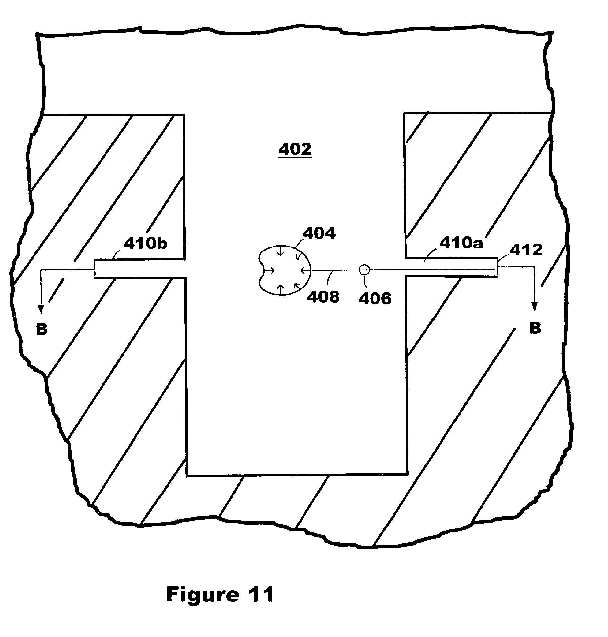
FIG. 12 is a top view looking into the pore of FIG. 11 showing multiple cavities formed at 90 degree angles in accordance with one embodiment of the present invention.

FIG. 13 is a top view looking into the cylindrical pore wherein a continuous slot has been fabricated in accordance with one embodiment of the present invention.

FIG. 14 is a cross sectional view of a cylindrical pore in where the re-entrant micro-jets from a working bubble directed through a target bubble are cutting a cavity at an angle not normal to the surface of the pore in accordance with one embodiment of the present invention.

FIG. 15 is a schematic view of a cavitation based process for injecting solution components into lissome in accordance with one embodiment of the present invention.

DETAILED DESCRIPTION OF THE PREFERRED EMBODIMENT(S)
The control and direction of the re-entrant micro-jet formed during the collapse of a cavitation bubble can provide a powerful tool for performing various fabrication and manipulation functions at a submicron and nanometer scale. A previous application (60/350,849 filed Jan. 18, 2002 entitled METHOD AND APPARATUS FOR THE CONTROLLED FORMATION OF CAVITATION BUBBLES) describes how these re-entrant micro-jets may be controlled through the use of an orifice placed between the work surface and the collapsing cavitation bubble. While the aforementioned techniques shall prove very useful for fabrication processes where the work surface can be placed in proximity to an orifice structure, there may be other applications where placing such a structure will be difficult or impossible. One example might be surgery inside the human eye, where a surgeon might wish to generate re-entrant micro-jets in the humus by focussing laser beams through the cornea. Another example might be to cut features into the side wall of micron sized pores in an integrated circuit structure where fabricating and placing submicron orifice structures would be very difficult.
The present invention teaches a technique by which the re-entrant micro-jet formed during the collapse of a cavitation bubble (working bubble) can be directed by the creation of a target bubble within a given proximity of the collapsing working bubble. Target bubbles can be created in any direction in 3d space relative to the center of the working bubble. All that is required is that there be a clear line of sight (relative to the radiation source needed to create the bubble) to the projected position of the target bubble, that the target bubble is formed within a given time period of the collapse of the working bubble, and that the target bubble be within a given proximity of the working bubble. The target bubble serves to attract the re-entrant micro-jet by creating a hydrodynamic condition similar to that of a solid work surface or an orifice. However, the target bubbles, unlike solid work surfaces, are transparent to the jets, and allow the jets to slice through them unimpeded. Target bubbles can therefore be used to direct the powerful re-entrant micro-jets toward a work surface or object without the need for an orifice. To be effective, a target bubble should be within approximately 6 working bubble diameters of the working bubble. A working bubble diameter is defined as the maximum diameter obtained by the working bubble just prior to collapse.
FIG. 1 is a cross sectional view of an apparatus 100 for generating target bubbles 102 and cavitation bubbles 104 in accordance with one embodiment of the present invention. A work piece 132 is placed in a container 134 filled with fluid 130. Components 108, 116, 118, 120, 124, and 138 make up the focussed laser device for creating the target bubble 102. Components 106, 110, 112, 114, 122, and 136 make up the focussed laser device for creating the cavitation working bubble 104. The lasers 106 and 108 may be chosen from among the group of CO2, Nd-YAG, dye, or excimer types. Other focussed energy devices such as x-ray and electrical discharge electrodes may also be used to create bubbles 104 and 106, as is well known to those skilled in the art. Alternatively, target bubbles 102 may be created by sparging gas though nozzles and orifices, and allowing them to rise through the fluid proximate to the working bubble. Radiation produced by laser 108 is collimated by lens components 116 and 120 and focussed distance 128 by lens 124. The intense laser radiation focussed into a small control volume vaporizes the liquid in that volume and creates the cavitation target bubble 102. In like manner, laser 106 and lens components 110, 114, and 122 create the cavitation working bubble 104 at a distance 126. Re-entrant micro-jet 140 is formed upon the collapse of the working cavitation bubble 104, and is attracted through target bubble 102 to work surface 132. By altering the angular orientation of lasers 106 and 108, and the focal distances 126 and 128, the re-entrant micro-jet can be positioned to impact anywhere on work surface 132. By altering the distance of the working bubble 104 to the work surface 132, the impact force of the jet may also be altered. To be effective in directing the re-entrant micro-jet, the target bubble should be approximately within six (maximum) working bubble diameters of the working bubble. The fluid in tank 134 can be any fluid that absorbs the laser radiation being utilized, but is preferably water or solutions containing water. The fluid may be re-circulated and filtered by additional pumps and components (not shown) to maintain an appropriate optical clarity.
FIG. 2 is a schematic view of a collapsing, working cavitation bubble 150 in relationship to a target bubble 152 in accordance with one embodiment of the present invention. As previously stated, distance 156 should be approximately less than six maximum working bubble diameters. To attract the re-entrant micro-jet formed as bubble 150 collapses, target bubble diameter 158 should be greater than approximately 10% of the maximum working bubble diameter. The projected path of the re-entrant micro-jet is shown by dashed line 154. Inwardly directed arrows 160 in bubble 150 illustrate the beginning collapse of the outer bubble surface. Concave surface 162 is indicative of the direction toward which the jet will be launched. Target bubble 152 may also be a cavitation bubble in an expanding or contracting state, as long as its diameter meets the minimum criteria stated above as working bubble 150 begins to collapse.
FIGS. 3a-3e are schematic diagrams showing a sequence for directing a re-entrant micro-jet toward a work surface through a target bubble in close proximity to the working bubble in accordance with one embodiment of the present invention.
FIG. 3a shows a target cavitation bubble 202 formed in close proximity to a working cavitation bubble 200. Both bubbles are initiated at approximately the same time, the arrows emanating from the surface pointing outward illustrate an expanding condition for each bubble. The target bubble 202 is placed between the working bubble 200 and the work piece 204. In this example; the target bubble 202 is within six working bubble diameters of the working bubble 200, and is also within six target bubble diameters of the working bubble 200. The working bubble 200 is greater than six working bubble diameters from the work piece 204. As illustrated, the target bubble 202 is smaller in diameter than the working bubble 200.
FIG. 3b shows the working bubble 206 and target bubble 208 at their maximum expanded diameters, just before they collapse.
FIG. 3c shows both bubbles 210 and 212 beginning to collapse, as illustrated by the inwardly directed arrows on their outer surface.
FIG. 3d shows the initial formation of the re-entrant micro-jets 216 and 218 by each of the bubbles 214 and 220, respectively. Due to their close proximity, opposing jets are launched from each bubble toward each other.
FIG. 3e shows the net effect of the re-entrant micro-jet 224 launched through the target bubble 220, 226 to the work surface 228. Since the working bubble 222 was initiated as a larger bubble in comparison to the target bubble, the re-entrant micro-jet launched from it (222) is dominant, resulting in a jet directed toward the work surface. However, the impact force imparted by jet 224 is reduced by the opposing interaction of jet 218 (launched from the target bubble 220, 226) on the initial jet 216. This phenomena may be utilized to moderate and control the impact force imparted by jet 224 on the work surface 204. The closer bubbles 206 and 208 are in maximum diameter, the lower the net force delivered to the work piece 204.
FIGS. 4a-4e are schematic diagrams showing a sequence for directing a re-entrant micro-jet toward a work surface through a target bubble far from the working bubble in accordance with one embodiment of the present invention.
FIG. 4a shows a target cavitation bubble 202 formed in moderate proximity to a working cavitation bubble 200. Both bubbles are initiated at approximately the same time, the arrows emanating from the surface pointing outward illustrate an expanding condition for each bubble. The target bubble 202 is placed between the working bubble 200 and the work piece 204. The working bubble 200 is greater than six working bubble diameters from the work piece 204. In this example, the target bubble 202 is within six working bubble diameters of the working bubble 200, but is greater than six target bubble diameters from the working bubble 200. As illustrated, the target bubble 202 is smaller in diameter than the working bubble 200.
FIG. 4b shows the working bubble 206 and target bubble 208 at their maximum expanded diameters, just before they collapse.
FIG. 4c shows both bubbles 210 and 230 beginning to collapse, as illustrated by the inwardly directed arrows on their outer surface.
FIG. 4d shows the initial formation of the re-entrant micro-jet 216 by bubble 214. Since target bubble 232 is further than six target bubble diameters from bubble 214, it does not "sense" (fluid mechanically) the presence of working bubble 214 and therefore will not launch a jet in its direction. However, target bubble 230 is within six working bubble diameters of bubble 214, attracting the re-entrant micro-jet from collapsing working bubble 214.
FIG. 4e shows the net effect of the re-entrant micro-jet 224 launched through the target bubble 226 to the work surface 228. The full force of the re-entrant micro-jet formed upon the collapse of the working cavitation bubble is applied to the work surface 228.
FIGS. 5a-5e are schematic diagrams showing a sequence for directing a re-entrant micro-jet toward a work surface at an angle in accordance with one embodiment of the present invention.
FIG. 5a shows a target cavitation bubble 202 formed in moderate proximity to a working cavitation bubble 200. Both bubbles are initiated at approximately the same time, the arrows emanating from the surface pointing outward illustrate an expanding condition for each bubble. The target bubble 202 is placed between the working bubble 200 and the work piece 204, situated to direct the re-entrant micro-jet from the working bubble 200 at an angle to the surface of 204. The working bubble 200 is greater than six working bubble diameters from the work piece 204. In this example, the target bubble 202 is within six working bubble diameters of the working bubble 200, but is greater than six target bubble diameters from the working bubble 200. As illustrated, the target bubble 202 is smaller in diameter than the working bubble 200.
FIG. 5b shows the working bubble 206 and target bubble 208 at their maximum expanded diameters, just before they collapse.
FIG. 5c shows both bubbles 210 and 230 beginning to collapse.
FIG. 5d shows the initial formation of the re-entrant micro-jet 216 by bubble 214. Since target bubble 232 is further than six target bubble diameters from bubble 214, it does not "sense" (fluid mechanically) the presence of working bubble 214 and therefore will not launch a jet in its direction. Target bubble 230 is within six working bubble diameters of bubble 214, attracting the re-entrant micro-jet from collapsing working bubble 214.
FIG. 5e shows the net effect of the re-entrant micro-jet 224 launched through the target bubble 226 to the work surface 234. The full force of the re-entrant micro-jet formed upon the collapse of the working cavitation bubble is applied to the work surface 234, at an angle 236. In this manner the target bubble may be used to direct the jet in any suitable angle with the work surface.
FIGS. 6a-6e are schematic diagrams showing a sequence for directing a re-entrant micro-jet toward a work surface at an angle, for working bubbles and target bubbles in close proximity to the working surface in accordance with one embodiment of the present invention.
FIG. 6a shows a target cavitation bubble 202 formed in moderate proximity to a working cavitation bubble 200. Both bubbles are initiated at approximately the same time, the arrows emanating from the surface pointing outward illustrate an expanding condition for each bubble. The target bubble 202 is placed between the working bubble 200 and the work piece 204, situated to direct the re-entrant micro-jet from the working bubble 200 at an angle to the surface of 204. The working bubble 200 is less than six working bubble diameters from the work piece 204. In this example, the target bubble 202 is within six working bubble diameters of the working bubble 200, but is greater than six target bubble diameters from the working bubble 200. As illustrated, the target bubble 202 is smaller in diameter than the working bubble 200.
FIG. 6b shows the working bubble 206 and target bubble 208 at their maximum expanded diameters, just before they collapse.
FIG. 6c shows both bubbles 240 and 242 beginning to collapse.
FIG. 6d shows the initial formation of the re-entrant micro-jet 248 by bubble 244. Since target bubble 246 is further than six target bubble diameters from bubble 244, it does not "sense" (fluid mechanically) the presence of working bubble 244 and therefore will not launch a jet in its direction. Since both the target bubble 246 and the working bubble 244 are within six working bubble diameters of the surface of work piece 204, the re-entrant micro-jet from collapsing working bubble 244 is launched in a direction between a path normal to the work surface and a path through target bubble 246. In the absence of any target bubble, the re-entrant micro-jet would be launched in a direction normal to the surface, but the location of impact would be unpredictable.
FIG. 6e shows the net effect of the re-entrant micro-jet 252 launched near the target bubble 254 (but not through it) to the work piece 204.
FIG. 7 is a schematic diagram of a working bubble 300 and a target bubble 304 directing convergent re-entrant micro-jets 302, 308 to a work surface 314 in accordance with one embodiment of the present invention. In this case, distance 312 is less than six working bubble diameters and distance 310 is less than six target bubble diameters. For target bubbles 304 significantly smaller than working bubbles 300, the re-entrant micro-jets emanating from the target bubble will be directed toward the surface 314. It is possible to adjust the spatial position of working bubble 300 in order to direct its re-entrant micro-jet 302 to a position convergent with jet 308 from the target bubble 304, as was shown in FIGS. 6a-e. This technique may be useful for amplifying the impact of the jets upon the work surface, or providing-jets from two different angles to the same location.
FIG. 8 is a schematic diagram 350 of three re-entrant micro-jets being directed at a movable work piece in accordance with one embodiment of the present invention. Three re-entrant micro-jets 370, 372, and 374 are directed at a movable section 354 of work piece 352. Jet 370 is formed by the collapse of cavitation bubble 356 through target bubble 362. Jet 372 is formed by the collapse of cavitation bubble 358 through target bubble 364. Jet 374 is formed by the collapse of cavitation bubble 360 through target bubble 368. Cavitation bubbles 356, 358, and 360 may be formed simultaneously or in a sequence, depending on the sequence of forces required to locate movable member 354 to its desired location 376. This process may be applied, for example, by a surgeon who wants to precisely locate a small section of tissue that has become detached from its desired position. A folded retina is one such possibility. By adjusting the distance of bubbles 356, 358, and 360 to work piece 354, and their maximum diameters, the forces imparted to tissue may be carefully adjusted to a level sufficient to do the job without imparting collateral damage to the structures being moved.
FIG. 9 is a cross sectional view 400 of a cylindrical pore 420 in which the re-entrant micro-jet 408 from a working cavitation bubble 404 directed through a target bubble 406 are cutting a cavity 410 in the side wall of the pore 402 in accordance with one embodiment of the present invention. Cavitation bubble 404 and target bubble 406 are nucleated within cylindrical pore 402. Re-entrant micro-jet 408 directed toward the wall of pore 402 cuts a channel 410 while impinging on surface 412. The depth of channel 410 will depend on the number of times bubbles 404 and 406 are generated. For pore diameters of 5 to 10 microns, re-entrant micro-jets on the order of 10 to 20 nanometers can be created, creating channels in the side walls in the 20 to 30 nanometer range. In silicon substrates, this could allow fabrication of trench capacitor structures of extremely small dimension, utilizing a volume of the substrate not accessible previously. The fabrication technology may enable true three dimensional device fabrication strategies to produce nanometer device geometry's without the use of lithography.
FIG. 10 is a top view looking into the cylindrical pore 402 of FIG. 9 in accordance with one embodiment of the present invention.
FIG. 11 is a cross sectional view of a cylindrical pore where the re-entrant micro-jets from a working bubble directed through a target bubble are cutting multiple cavities in accordance with one embodiment of the present invention. Cavitation bubble 404 is shown cutting multiple cavities 410a and 410b. This can be accomplished by placing target bubble 406 in the appropriate direction.
FIG. 12 is a top view looking into the pore of FIG. 11 showing multiple cavities formed at 90 degree angles in accordance with one embodiment of the present invention. By positioning the target bubble 406 on dotted circular path 414 at positions 418, 416, and 420 cavities 410b, 410c, and 410d can be fabricated, respectively. Although four cavities are shown in this figure, many others at any desired spacing can be fabricated as will be appreciated by those skilled in the art.
FIG. 13 is a top view looking into the cylindrical pore of FIG. 11 wherein a continuous horizontal slot has been fabricated in accordance with one embodiment of the present invention. When a series of cavitation target bubbles 406 are moved in a continues manner along path 414, a resulting horizontal slot at depth 412' can be produced. By altering the depth that working bubble 404 and target bubble 406 are situated in the pore 402, multiple horizontal slots at varying depths can be fabricated as well. Due to the intense power of the re-entrant micro-jets, the hardest materials can be eroded with this technique, including crystalline silicon. Multiple slots produced in a horizontal fashion could provide a basis for very high surface area capacitors for advanced memory devices.
FIG. 14 is a cross sectional view of a cylindrical pore 402 in where the re-entrant micro-jets 408 from a working bubble 404 directed through a target bubble 406 are cutting a cavity at an angle not normal to the surface of the pore in accordance with one embodiment of the present invention. In this case target bubble 406 is placed in a horizontal plane above or below cavitation bubble 404. If the position of bubbles 404 and 406are held constant, the re-entrant micro-jet 408 will cut a cavity 422 at an angle to the vertical wall of pore 402. By placing target bubble 406 at fixed depth intervals, cavities at various angles of depth 426 can be produced. By adjusting the depth of target bubble 406 in a continues manner, a larger cutout following the outline 424 may be obtained. By applying the techniques illustrated in the previous FIGS. 9-14, practically any profile or shape can be fabricated in the walls of a pore.
FIG. 15 is a schematic view of a cavitation based process for injecting solution components into liposomes in accordance with one embodiment of the present invention. Liposomes are microscopic, fluid-filled pouches whose walls are made of layers of phospholipids identical to the phospholipids that make up cell membranes. The fluid inside the pouch may contain soluble drugs designed to be delivered to cells when the liposomes merge with the cell walls of a targeted cell. One way to inject the drug into the interior of a liposome is shown in via the apparatus 450 in this figure. A container 452 contains a fluid solution 454, a liposome manufacturing module 456 (which can also reside outside the walls of container 452), and a nozzle 458 for delivering liposomes 460 to the fluid 454. The liposomes may be manufactured with no drugs in their interiors, some amount of the desired drug, or a mixture of completely different drugs. The drugs to be injected are present in the solution 454. In one example, a cavitation bubble 464 is nucleated within five bubble diameters of a liposome 460b. The liposome acts like a target bubble, attracting the re-entrant micro-jet 472. Adjustment of the control volume and initial energy dose will determine the size of the cavitation bubble, and therefore the size of micro-jet 472. The collapsing cavitation bubble entrains components of the solution 454, including the drugs to be injected, and the micro-jet 472 delivers these components through the wall of the liposome 460b. In a second example, a target bubble 468 is nucleated in the proximity to a working bubble 462, in such a manner as to direct a re-entrant micro-jet 470 into the interior of liposome 460a. This method allows the working bubble 462 to be a further distance from liposome 460a, allowing additional flexibility in reducing dosage levels injected into the liposome, as well as reducing the potentially damaging impact of a jet launched in close proximity.
US7517430
Method and apparatus for the controlled formation of cavitation bubbles
Method and apparatus for the controlled formation of cavitation bubbles
Inventor: LECLAIR MARK L [US]
EC: A61B18/26
IPC: A61B18/26 C23C16/00 H01B13/00
2009-04-1
The present invention discloses a method and apparatus for the directed formation of a re-entrant micro-jet formed upon the collapse of a cavitation bubble formed proximate to a work surface placed in a fluid. A mask containing an orifice, placed between the work surface and the cavitation bubble, is utilized to direct the re-entrant micro-jet to the work surface. The cavitation bubble may be formed in the desired location by focusing an energy flow proximate to the mask. The energy flow may be obtained by radiation from laser, x-ray, or electrical discharge sources.
Description
BACKGROUND OF THE INVENTION
1. Field of the Invention
This invention relates generally to the formation and control of individual micron size and submicron size cavitation bubbles for use in nanofabrication operations. More particularly, embodiments of the invention teach methods and apparatus for control of a re-entrant micro-jet formed upon collapse of an individual or array of cavitation bubbles and directing the impact of the micro-jet toward a work surface with a high degree of precision.
2. Description of the Related Art
In general, the production of cavitation has been a phenomena many have tried to avoid. Cavitation in a liquid is the formation, growth, and collapse of gaseous and vapor bubbles due to the reduction of pressure below the vapor pressure of the liquid at the working temperature. Pump impellers, boat props, and similar applications experience cavitation which can produce rapid damage and erosion of surfaces. It has been well known for many years that ultrasonic cleaning devices, which function by the creation of cavitation bubbles, can produce significant surface damage to even the hardest of materials. Studies by a number of authors have revealed that one significant element in producing the damage caused by cavitation occurs when a cavitation bubble collapses in the vicinity of a surface, launching what is called a re-entrant micro-jet toward the surface. This liquid jet can produce velocities as high as 1500 m/s, and is capable of damaging the hardest materials known.
Recently, a number of applications have been developed utilizing the formation of cavitation bubbles through the use of laser light or electrical discharge. Esch et al. (U.S. Pat. No. 6,139,543) and Herbert et al. (U.S. Pat. No. 6,210,400) disclose the use of laser light introduced into a catheter device for the purpose of creating cavitation bubbles, whose expansion and collapse are utilized to pump fluids in and out of the catheter. Hammer et al. (U.S. Pat. No. 5,738,676) discloses a laser surgical probe with a special lens designed to produce the cavitation bubbles further from the end of the fiber optics, to reduce the damage formed (presumably by the re-entrant micro-jets launching into the lens on the end of the cable). Such damage was also reported by Rol et al. in "Q Switched Pulses and Optical Breakdown Generation Through Optical Fibers", Laser and Light in Opthalmology, Vol. 3, No. 3, 1990. Palanker (U.S. Pat. No. 6,135,998) describes a method for performing electrosurgery using sub-microsecond, high power electrical pulses are applied to an electrosurgical probe interface. The tool described by Palanker provides a cutting force by both the plasma generated by the electrical arc and shock waves produced by collapsing cavitation bubbles.
In each of the prior art references cited above, there has been no attempt to control the direction and impact of the powerful micro-jets formed upon the collapse of the cavitation bubbles created when highly focused energy is introduced into a liquid. Without such control, concern of collateral damage cannot be avoided, especially when such tools are used in the human body in a medical application.
Recently as well, there has been a significant interest generated in the field of nanotechnology, for methods needed to fabricate micron and submicron devices and nanomachines. There are very few fabrication tools available that can cut, drill, peen, deform, or otherwise modify features of a surface on a submicron to nanometer scale. Much of the technology developed by the semiconductor industry requires the fabrication of structures utilizing photolithographic processing. This technology is not as flexible as may be required, and will have certain difficulties when applied to biological nanotechnology systems. Advancing the state of the art required by nanotechnology applications will require fabrication technologies operating at least 1 to 2 orders of magnitude below that capable in the semiconductor process arena.
The prior state of the art therefore has yet to provide a fabrication technology capable of operating in the nanometer region by harnessing the powerful phenomena of the re-entrant micro-jet formed during the collapse of a precisely located cavitation bubble.
SUMMARY OF THE INVENTION
An apparatus for the controlled formation of cavitation bubbles in accordance with the present invention includes a mask immersed in a liquid proximate to a work surface, wherein the mask has a first surface opposing and separate from the work surface, a second surface opposing the first surface, and at least one aperture extending from the first surface to the second surface. The apparatus further includes an energy source capable of generating an energy flow in the liquid sufficient to create at least one cavitation bubble, the cavitation bubble being located opposite the second surface proximate to the aperture, wherein a collapse of the cavitation bubble creates a re-entrant micro-jet directed through the aperture at the work surface.
BRIEF DESCRIPTION OF THE DRAWINGS
FIG. 1A is a schematic view of a cavitation initiation volume in accordance with one embodiment of the present invention.

FIG. 1B is a schematic view of a fully expanded cavitation bubble in accordance with one embodiment of the present invention.
FIG. 1C is a schematic view of a collapsing cavitation bubble in accordance with one embodiment of the present invention.
FIG. 1D is a schematic view of the initial formation of a re-entrant micro-jet induced by the collapsing cavitation bubble in accordance with one embodiment of the present invention.
FIG. 1E is a schematic view of a re-entrant micro-jet directed through an aperture to a work surface in accordance with one embodiment of the present invention.
FIG. 2 is a schematic view of a lens focused laser apparatus for producing cavitation induced re-entrant micro-jets in accordance with another embodiment of the present invention.

FIG. 3 is a schematic view of a parabolic mirror focused laser apparatus for producing cavitation induced re-entrant micro-jets in accordance with another embodiment of the present invention.

FIG. 4 is a schematic view of a lens focused x-ray source apparatus for producing cavitation induced re-entrant micro-jets in accordance with another embodiment of the present invention.

FIG. 5 is a schematic view of a parabolic mirror focused x-ray source apparatus for producing cavitation induced re-entrant micro-jets in accordance with another embodiment of the present invention.

FIG. 6 is a schematic view of spatial filter added to a lens focused laser apparatus for producing cavitation induced re-entrant micro-jets in accordance with another embodiment of the present invention.

FIG. 7 is a schematic view of an electric discharge apparatus for producing cavitation induced re-entrant micro-jets in accordance with another embodiment of the present invention.

FIG. 8 is an apparatus for the production of an array of cavitation induced re-entrant micro-jets in accordance with another embodiment of the present invention.

FIG. 9 is a schematic view of an apparatus for the welding of small particles in a cavitation induced re-entrant micro-jet in accordance with another embodiment of the present invention.
FIG. 10 is a table of parameters for the application of various pulsed Gaussian TEMOO lasers for a number of embodiments in accordance with the present invention.

FIG. 11 is a table of parameters for the application of an electric discharge for one embodiment in accordance with the present invention.

DETAILED DESCRIPTION OF THE PREFERRED EMBODIMENT(S)
The sequence illustrated in FIGS. 1A-E illustrate the formation of a re-entrant micro-jet from the formation and collapse of a cavitation bubble in accordance with the present invention.
FIG. 1A is a schematic view of a cavitation initiation volume in accordance with one embodiment of the present invention. The energy from a cavitation initiation device (not shown) is focused into a volume 2 aligned over aperture 4, at a nominal distance 3 from aperture mask 6 placed in proximity to a work piece surface 8. The intense energy focused into the small focus volume 2 is absorbed by the fluid 1, causing rapid boiling and expansion of vaporized gasses. Arrows 10 represent the rapid movement of the gas liquid boundary of the cavitation bubble formed in volume 2. Energy sources may include, but are not limited to: lasers, x-ray sources, ultrasound, electrical discharge, and positrons.
FIG. 1B is a schematic view of a fully expanded cavitation bubble in accordance with one embodiment of the present invention. Cavitation bubble 12, formed from the rapid expansion of vaporized fluid in volume 2 and the momentum of liquid moving away from the center of the focus volume 2, has reached its maximum diameter 5. Typically, the maximum diameter 5 of the fully expanded cavitation bubble 12 is approximately 10 to 50 times the diameter of the focus volume 2 shown in the previous FIG. 1A. Gas pressure inside fully expanded cavitation bubble 12 may be as low as the vapor pressure of fluid 1 at it's bulk temperature. The pressure of the surrounding fluid 1, typically at 1 atmosphere absolute or higher, creates a pressure differential on the outer surface of the bubble 12, driving its subsequent collapse. For fluids 1 such as water at 1 atmosphere and 25[deg.] C., the pressure differential can exceed 700 torr.
FIG. 1C is a schematic view of a collapsing cavitation bubble in accordance with one embodiment of the present invention. Cavitation bubble 14 has begun a rapid collapse illustrated by rapid inner movement of its outer surface and arrows 16.
FIG. 1D is a schematic view of the initial formation of a re-entrant micro-jet 20 induced by the collapsing cavitation bubble 16 in accordance with one embodiment of the present invention. Re-entrant micro-jet 20 is launched through aperture 4 toward work surface 8. Aperture mask 6 serves to block subsequent shock waves produced by collapsing cavitation bubble 16 from work surface 8, allowing only the high velocity, focused re-entrant micro-jet to impact the surface.
FIG. 1E is a schematic view of a re-entrant micro-jet directed through an aperture to a work surface in accordance with one embodiment of the present invention. The fully formed re-entrant micro-jet 24 impacts the work surface 8 through aperture 4. The re-entrant micro-jet 24 may impact the work surface with velocities as high as 1500 meters/second, and is capable of removing material from the hardest surfaces known, such as diamond. These jets may be used to cut, machine, drill through, erode or deform features on the work surface 8. The diameter of the jets are determined by the size of the cavitation bubble 12 formed, which in turn is determined by the dimensions of the focus volume 2 and the level of energy introduced into said focus volume. As will be illustrated in subsequent figures, the re-entrant micro-jet 24 diameters may vary from about 1 micron to about 1 nanometer for focused laser and x-ray energy sources. Electric discharge sources may produce re-entrant micro-jet diameters on the order of 10 to 15 microns. The velocity of the re-entrant micro-jet through the aperture is primarily determined by the distance 3 of the focus volume 2 to the aperture mask 6, and can vary from [1/2] the expanded bubble diameter 5 to about 6 times the expanded bubble diameter 5, with the optimum distance being approximately 3 expanded bubble diameters 5. The impact force of the re-entrant micro-jet 24 on work surface 8 may be adjusted by altering the distance 7 between the aperture mask 6 and the work surface 8. At a given jet velocity (or fixed distance between the focus volume 2 and aperture mask 6), the impact force will vary inversely with the distance 7, in a range from approximately zero to 6 expanded bubble diameters 12, but preferably in a range from zero to 4 bubble diameters 12. The diameter of the aperture 4 can be in a range from about 1% to 30% of the expanded bubble diameter. The re-entrant micro-jet diameter is on the order of about 0.2% of the expanded bubble diameter 12.
The aperture mask 6 and aperture 4 play an essential role in directing and controlling the action of the re-entrant micro-jet 24. Without the aperture mask, the collapse of the cavitation bubble (12, 14, 16) would still launch a re-entrant micro-jet toward the surface 8, but the location of impact and the force imparted would be unpredictable, especially on a nanometer scale. In addition, the aperture mask tends to keep shock waves created in the expansion and contraction stages from damaging the surface 8. Accurate placement of the aperture and the focus volume allow nanometer scale precision cutting, punching, peening, drilling, or deforming operations on sub-micron scale features of the work surface. Many prior art applications are capable of accurate placement of the initial focus volume, but do little or nothing to control the shock waves and re-entrant micro-jet formed upon collapse of the cavitation bubble.
FIG. 2 is a schematic view of a lens focused laser apparatus for producing cavitation induced re-entrant micro-jets in accordance with another embodiment of the present invention. Sealed tank 30 contains liquid filled to a level 32. Various liquids can be used, but high purity water (>100 k ohms resistivity) is preferred. The beam from laser 34 is directed to lenses 40a and 40b to collimate the beam, which is then focused by lens 48 at a focal distance 50. Beam focus positioner 36 determines the location of the focus volume 2 relative to the aperture mask 6, at a distance 52. Work surface 8 is moved by precision XYZ stage 60, to adjust the distance from aperture mask 6 to the work surface, as well as locate the specific area on the work surface to be impacted by the jet 24. Recall from previous FIGS. 1A-E, that the position of the focus volume determines the location of the subsequent cavitation bubble 44 and re-entrant micro-jet 24. Fluid inlet 56 and outlet 58 are utilized to provide a constant flushing of the fluid in the tank 30, in part to remove any debris produced by the machining occurring on the work surface 8. This debris may negatively impact the absorption of subsequent laser light pulses in the focus volume, as well as potentially contaminate the surface with entrained particle matter introduced into the re-entrant micro-jet. For similar reasons, it may be desirable (although not essential) to filter the incoming fluid stream 62 to remove any particulate contamination. Tank 30 is equipped with a pressure transducer 38 to monitor and control the back pressure. For a sealed tank as shown, this may be done simply by raising the inlet pressure of incoming fluid stream 62 with respect to the outlet pressure of outlet stream 64, by choking the outlet flow until the tank ambient pressure is as desired, the re-equilibrating the flows once again.
FIG. 3 is a schematic view of a parabolic mirror focused laser apparatus for producing cavitation induced re-entrant micro-jets in accordance with another embodiment of the present invention. As was shown in FIG. 2, laser 34 directs a beam into collimator lenses 40a and 40b. The collimated beam is directed onto a parabolic mirror 66, which also contains the aperture 4. Parabolic mirror 66 focuses the collimated laser beam to a focus volume at a distance 52 from the aperture. In this embodiment, distance 52 is fixed by the curvature parameters of the parabolic mirror 66, and therefore the velocity of the re-entrant micro-jet 24 is also fixed. An XYZ stage 60 determines the distance 54 from the aperture to the work surface, as well as the XY coordinates of the area to be worked on. All other features are as described in FIG. 2.
FIG. 4 is a schematic view of a lens focused x-ray source apparatus for producing cavitation induced re-entrant micro-jets in accordance with another embodiment of the present invention. X-ray source 70 directs a beam into x-ray lens 72, which focuses and concentrates the x-ray beam into a focus volume at a distance 52 from an aperture mask 6. Aperture positioner 76 adjusts distance 52 to alter re-entrant micro-jet velocity through the aperture 4. Dimension 54, or the distance of the aperture mask to the work surface 8 is adjusted by XYZ stage as has been previously described. All other features are as described in FIG. 2.
FIG. 5 is a schematic view of a parabolic mirror focused x-ray source apparatus for producing cavitation induced re-entrant micro-jets in accordance with another embodiment of the present invention. X-ray source 70 directs a beam onto parabolic x-ray mirror 80 containing an aperture 4. The x-ray beam is focused into a focus volume at a distance 52 from the aperture 4. The dimension 54 between the aperture mask 6 and work surface 8 is adjusted by the XYZ stage 60. In this embodiment, distance 52 is fixed by the curvature parameters of the parabolic mirror 80, and therefore the velocity of the re-entrant micro-jet 24 is also fixed.
FIG. 6 is a schematic view of spatial filter added to a lens focused laser apparatus for producing cavitation induced re-entrant micro-jets in accordance with another embodiment of the present invention. Spatial filter 86 can be optionally added to the previously described embodiments to further clean up the laser beam or x-ray beam to allow smaller focus volumes. The spatial filter 86 comprises a entrance lens 82, a pinhole 85, and an exit lens 83. Exit lens 83 and lens 40 makes up part of the collimator lens pair as shown in previous figures.
FIG. 7 is a schematic view of an electric discharge apparatus for producing cavitation induced re-entrant micro-jets in accordance with another embodiment of the present invention. A positive electrode 88 and negative electrode 90 are immersed in fluid 32 and positioned to generate an arc at a position a distance 52 above aperture mask 6. Actuator 76 adjusts dimension 52 to position the focus volume a known distance from the aperture mask 6. The arc is created by rapid discharge of capacitor 96 through switch 94. Full circuit details are not shown in FIG. 7, but are well known to those skilled in the art. Capacitor 96 is a low inductance, high voltage device as is used in pulse lasers and flash tubes. The rapid discharge and subsequent transient arc create a cavitation bubble 44 as illustrated in FIGS. 1A-E.
FIG. 8 is an apparatus for the production of an array of cavitation induced re-entrant micro-jets in accordance with another embodiment of the present invention. Work surface 8 is placed parallel to an aperture mask 6' containing a plurality of apertures. Cavitation bubbles 44a, 44b (only two are shown for clarity) are formed directly over each aperture in the array by any number of techniques, as previously discussed, such that the re-entrant micro-jets 24a, 24b formed following the collapse of the cavitation bubbles are directed through the apertures 4a, 4b normal to the surface 6' and impact work surface 8. The cavitation bubbles may be formed simultaneously or sequentially, or in some other pattern (such as every other aperture, every two apertures, etc.). If the cavitation bubbles 44 are formed over each aperture simultaneously, then the aperture spacing dimensions 100 and 102 must be determined such that they are at least 6 expanded bubble diameters 12 long. These dimensions may be shortened, for example, to 3 expanded bubble diameters 12 if the cavitation bubbles are formed over every other aperture, as long as there remains at least 6 fully expanded bubble diameters between any two cavitation bubbles in the array being formed simultaneously. For cavitation bubble spacing closer than the 6 expanded bubble diameters, there is some probability (increasing with decreasing bubble spacing) that the re-entrant micro-jets produced on collapse of the adjacent cavitation bubbles will be directed toward each other, as opposed to being directed through the apertures. This is undesirable. Alternatively, aperture mask 6' may be moved relative to work surface 8 to place the impact location of the various re-entrant micro-jets in any desired location on the work surface.
The array of cavitation bubbles may be produced by a number of techniques in accordance with the present invention. For example, an array of lasers as illustrated in FIGS. 2, 3, and 6 may be employed. Or a single laser having a fiber optic array employing multiple collimators located over each aperture 4a, 4b may also be used. Additionally, a single laser and collimator may be scanned over the aperture array such that each "firing" of the pulse laser produces a focus volume of light energy over the appropriate aperture position. The same process may also be utilized with the x-ray source. Additionally, the aperture location may be moved by XYZ stage 60 while holding the aperture mask 6' fixed over the work surface 8, utilizing a single laser or x-ray source. For the case of the electrical discharge, a multiple electrode array may be used, or the array may be positioned under a single electrode pair via the XYZ stage. An array of cavitation bubbles may also be produced by ultrasound techniques. It is well known to those skilled in the art, that many ultrasound transducers produce a three dimensional array of cavitation bubbles in a tank of fluid corresponding to a standing wave pattern of sound waves in the fluid. By creating and positioning such a standing wave pattern over the aperture mask 6', cavitation bubbles formed due to the ultrasound will collapse, directing the previously described re-entrant micro-jets through the apertures to the work surface. Not every cavitation bubble produced in the standing wave field need be located over an aperture. Those that are not will simply launch their respective jets against the mask 6'. It is important that no cavitation bubbles are formed between the mask 6' and the work surface 8. These bubble may damage the surface since the impact of their jets would uncontrolled and potentially misdirected. The properties of the ultrasound generated cavitation bubbles should conform to previously determined requirements as discussed in FIG. 1E.
FIG. 9 is a schematic view of an apparatus for the welding of small particles in a cavitation induced re-entrant micro-jet in accordance with another embodiment of the present invention. Introduction of particulate matter 112 into the re-entrant micro-jet may result in the welding of the particles to each other and/or to the work surface 8. Small particles 108 stored in a container 106 are released into solution via valve 110 in the vicinity of the focus volume 2, where a cavitation bubble will be nucleated, as previously described. Particles 108 may be stored in a dry form, but preferably are mixed and suspended in a compatible fluid. Once in solution, these particles 112 will accumulate at the gas liquid interface of the cavitation bubble, and may be entrained into the re-entrant micro-jet as the cavitation bubble collapses. The very high impact forces of the micro-jet hitting the work surface causes the welding of these particles to each other and the work surface 8. This process may be used to build microstructures of various types of materials on the work surface. One application of importance would include the construction of photo resist masks for micro and nano circuit fabrication. Since photo lithography is not required for this process, the lower limits imposed by that process can be easily exceeded. The fabrication of submicron and nano scale particles is well known to those skilled in the art, as is the technology for suspending such particles in a fluid. By translating work surface 8 under aperture 4 while sequentially forming a series of cavitation bubbles 2, many types of submicron layer structures can be built. The materials making up these structures can also vary considerably, and may include polymers, metals, and inorganic ceramic materials. Some of these materials may have superior etch, resist properties that conventional organic films used today do not posses. Additionally, cavitation welded films may not need curing and baking as is required for conventional polymer photo resists.
FIG. 10 is a table of parameters for the application of various pulsed Gaussian TEM00 lasers for a number of embodiments in accordance with the present invention. In this table, the relationships between various laser parameters (such as laser type, spectrum of the emitted radiation and wavelength, collimated beam radius, focus diameter, and cylindrical focus volume) and the resulting cavitation bubble parameters (such as the cavitation bubble diameter and the re-entrant microjet diameter) are shown. All parameters are normalized to a collimated laser beam diameter of 10 mm. This dimension was chosen for convenience, and does not imply that collimated laser beams of larger or smaller dimensions are not applicable. In one example, a CO2 laser beam of 10 mm producing an infra-red wavelength of 10.6 microns is focused to a 10.8 micron diameter in the fluid. This focused beam results in a control volume 2.8*10<-9 >cm<3>, generating a cavitation bubble 520 microns in size at maximum diameter. After collapse, this cavitation bubble produces a re-entrant micro-jet of 1200 nanometers in diameter. In a second example, an excimer laser beam of 10 mm producing an ultra-violet wavelength of 0.13 microns is focused to a 0.13 micron diameter in the fluid. This focused beam results in a control volume 5.1*10<-15 >cm<3>, generating a cavitation bubble 6.4 microns in size at maximum diameter. After collapse, this cavitation bubble produces a re-entrant micro-jet of 14 nanometers in diameter. In yet a third example, an x-ray beam of 10 mm producing an x-ray wavelength of 0.01 microns is focused to a 0.01 micron diameter in the fluid. This focused beam results in a control volume 2.3*10<-18 >cm<3>, generating a cavitation bubble 0.49 microns in size at maximum diameter. After collapse, this cavitation bubble produces a re-entrant micro-jet of 1.1 nanometer in diameter. As can been seen from the aforementioned examples, re-entrant micro-jets ranging over 3 orders of magnitude in diameter can be produced by changing the type of laser energy used to create the cavitation bubble, and can produce the smallest jets on the order of 1 nanometer in diameter.
FIG. 11 is a table of parameters for the application of an electric discharge for one embodiment in accordance with the present invention. For convenience, the data presented is based on the discharge of a 1 micro Farad capacitor. Capacitor values greater or smaller than this value are also equally applicable. In one example, the 1 micro Farad capacitor is charged to 5000 volts and discharged into the fluid generating a cavitation bubble 6 mm in diameter, creating a re-entrant micro-jet of approximately 14 microns in diameter. In a second example, the 1 micro Farad capacitor is charged to 2000 volts and discharged into the fluid generating a cavitation bubble 3 mm in diameter, creating a re-entrant micro-jet of approximately 8 microns in diameter.
US5522553
Method and apparatus for producing liquid suspensions of finely divided matter
Method and apparatus for producing liquid suspensions of finely divided matter
Inventor: LECLAIR MARK L [US]
HIGGINS JOHN A [US]
Applicant: KADY INTERNATIONAL [US]
EC: B02C18/00W2 B02C18/06B
IPC: B02C18/06 (IPC1-7):B02C18/40
1996-06-04


