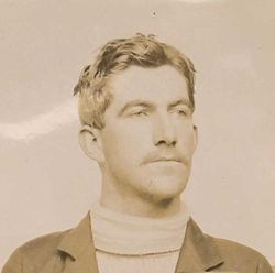
Roy J. MEYERS
Absorber
C. Edholm: "Picks Power from Air" ( Technology
World
Magazine, 1912 ? )
Dr L. Hirshberg: "Electricity from Air New
Great Discovery (Modern Electrics, 1914 ? )
R. J. Meyers: British Patent # 1098
(1913) --- Improvements in and Relating to
Apparatus for Producing Electricity
Notes & Comments
R. J. Meyers: British Patent # 1098 (1913)
--- JPG version
A remarkable scene took place in the legislature of Arizona this spring when the lawmakers enthusiastically voted for the parole of a certain convict in the State penitentiary, granting him a leave of absence for 30 days and by means of private contributions raising a fund to defray his expenses to Washington DC and return.
The prisoner, Roy J. Meyers, is serving a 3-1/2 year sentence, but in spite of the fact that he bears the stigma of a convicted lawbreaker, he has demonstrated that a convict can be a useful member of society. During his imprisonment he perfected an electrical device of such original character as to arouse feelings of wonder and skepticism until experts had seen it in actual operation. It is a device to draw electricity from the atmosphere for light and power, and the 30-day parole was granted in order that the inventor might protect his rights through the patent office at Washington.
With the acquiescence of the legislature, Governor Hunt granted the parole and the prisoner was allowed to go free without any guard or any assurance but his word of honor that he would return. Two days before the period had elapsed, Meyer again presented himself before the governor, having accomplished his mission, and then returned to the penitentiary at Florence, where he continues to serve his sentence.
This, in brief, is the picturesque story which has called attention of the civilized world to a newly discovered electrical genius, and to another feature of the case which is of equal importance and human interest; namely, the enlightened policy pursued by our youngest State in its treatment of convicts...
Before entering the prison, Meyer had already applied for various patents, among them one for an improved trolley wheel head which prevents the trolley wheel from jumping the wire. Meyers had a conference with Superintendent Sims and Parole Clerk Sanders, and it was to these gentlemen that the inventor first explained the principles of his new device for securing electrical energy from the air. The officials were willing to give the man the opportunity to develop his plan and a little wooden building outside the walls was turned over to Meyers and was fitted up as a workshop and a laboratory. The first demonstration of the new apparatus was made shortly thereafter, the electricity drawn from the atmosphere being used to spark the gas engines of the pump house, and although the device was crude yet it did the work, and removed the doubts of his friends. Furtter development of the "absorber" followed, and his second model was constructed, and developed 8 volts. The machine came to the attention of the remarkable woman who brought his name before the legislature.
This was Miss Kate Barnard, State Commissioner of Charities and Corrections of Oklahoma, who was a guest of Mr. Sims, while studying prison conditions. She saw the machine at work, became familiar with the facts of Meyers' case, and was impressed by his rather blunt and unaffected personality, for Meyers has nothing of the polish or glibness of the poseur. He is a simple, earnest student of mechanical problems and not the sort of man to make a sentimental appeal for sympathy because of any grace of person or manner. Therefore it was the value of Meyers' invention, together with his essential integrity (in spite of his lapse) which so strongly impressed Miss Barnard that when she appeared before the Arizona legislature not long afterwards, addressing that body on the need of enlightened legislature along the line of her own work, she told the story of Roy Meyers and his epoch-making invention.
So, early in May, Meyers set out for Washington, unaccompanied.
In his own words: "When I arrived in Washington and laid my plans before the patent office experts, they merely smiled and told me that I would have to build a model and demonstrate my claims --- that it seemed strange that I, unknown as I am in the electrical world, should have accomplished the things for which Edison, Tesla and other experts have been striving for years.
"They could grasp the meaning of my drawings nor the explanation I tried to make to them. There was little time to spare, as I had only 20 days left of my leave, but I set to work in a few days was able to take a crude model around to the patent office to make a demonstration.
"Arriving at the patent office I telephoned to a friend who had been so kind as to introduce me and aid me in reaching the proper officials. The absorber was hoisted on two short poles and made to work. While they were as yet unable to understand the principles involved and hardly willing to believe their eyes, they were forced to admit that I had something new and different, and they told me that there would be no further objection; that I might file my application without further delay.
"I hope to construct my first large machine right here in Phoenix. I feel grateful; to Governor Hunt and others for what they have done for me and to the help they have given in securing protection I might not otherwise have had, and I am desirous of demonstrating this gratitude. I am going back to Florence today to resume the serving of my sentence, which will expire in 10 months. Then, here in Phoenix, I will begin the work of making my machines."
While there are some details of the device which the inventor refuses to make public, yet there are many general features that may be explained. It is planned that the machine, to be set up in Phoenix, will generate sufficient power to light the city, and will consist of a 200 foot tower upon which is placed the "absorber". The latter consists of a series of magnetized steel plates set in a circle (the manner of preparing them is kept secret) and this mechanism attracts the electricity from the atmosphere. This is carried by wires to a transformer in the engine house below and thence is applied to produce either power or light after the usual manner.
In an authorized statement Meyers says: "The flow of electricity is constant. When it emerges into the transformer it is in the form of a direct current. It will absorb the electricity day and night and will work whenever the wireless will work. I can put up a plant to supply such a building as the Adams Hotel for about $1500, and one of the principal items of the expense is the cost of the towers, the wires, the magnetizing of one set of plates, which is part of the secret of the treatment which makes it respond to the accumulations of the atmosphere.
"For use in the case of an electrical storm I have made what I call a modified form of circuit breaker, such as is commonly used as a lightning arrester on telegraph lines. In case of a storm the accumulator would suddenly become overcharged, possibly, and as the electricity would not of itself flow back into the air, the result might be disastrous. So I send it down into the ground, whenever the voltage rises above a certain amount."
Roy J. Meyers & the "Absorber"

Electricity From Air New Great Discovery
by Dr Leonard Keene Hirshberg
Working quietly in the heart of Baltimore for weeks on an invention which some critics say will revolutionize the method of converting electricity to practical use has been Roy J. Meyers, who like Benjamin Franklin, extracts the electric current from the air.
Mr Meyers invention was made last summer while he was confined in the penitentiary at Florence, Arizona. His first finished apparatus was made in Baltimore.
A practical, unlettered electrician, Mr Meyers, while in Arizona, was arrested on a comparatively minor charge and sent to the penitentiary. There he was placed in charge of the prison electrical plant, and there he says he made his discovery that the current which the civilized world is beginning to use most extensively for light and power could be transformed from the atmosphere without the aid of moving machines or batteries.
Miss Kate Barnard, Commissioner of Charities and Corrections, of Oklahoma, hearing of Meyers’ invention and of his desire to have it patented, appeared before the Arizona Legislature to make an appeal in behalf of the young convict. As a result a special bill was passed which granted Meyers a month’s leave of absence on parole. He went unaccompanied to Washington, filed his patent applications and returned to the penitentiary. Since then he has been indefinitely paroled.
He came to Baltimore as the place where he could easily obtain the mechanical parts needed to make a more nearly perfect machine than the crude model he has fashioned in the penitentiary workshop, and is making his headquarters here while working on his invention. With him is W.E. Chenot, who has been his assistant in assembling and testing the machine and who says that he has bought Meyers’ patent rights for Germany.
They have proved beyond doubt that the invention is practical and that when finally brought to a state of perfection it will introduce a new epoch in the industrial use of electricity. By Westinghouse meters they tested the strength of the current gathered from the air, and with the use of only two of the four rectifying transformers the voltmeter recorded four and one-half volts, and the ammeter, which had the capacity of recording 75 amperes, was broken by the force of the current.
The machine itself is simple. It is in reality a transformer, which is familiar to anyone knowing anything at all about electricity in its practical uses. On a high tripod, which resembles somewhat the framework of a windmill tower, is the transformer, which Mr Meyers calls his ‘absorber’. It is made up of an iron core, wrapped with copper wire. The secret of the invention is the manner in which the disks composing this ‘absorber’ are magnetized, and this secret Meyers says he found by accident while at work in prison.
What the machine, when finally perfected, will do is yet to be seen. Its inventor claims that it will greatly reduce the cost of making electricity. No batteries of any kind are needed, he says, and not a part of the machine turns upon the other. It is as durable, apparently, as an electric light pole. One of these machines, says Meyers, when perfected may be placed on a vehicle and transform enough electricity to give motive power, be that vehicle a locomotive or an automobile. He declared it can be placed on a building to furnish electric lights or power, and that the only wear will be upon the machinery which its current runs.
Meyers is 34 years old and he gained his knowledge of electricity by working in shops along the Pacific Coast. The depths of the mysteries of electricity he has not explored, but he is certain that he has found the means of absorbing it from the air and of converting it to the use of mankind.
GB191301098
Improvements in and Relating to Apparatus for Producing
Electricity.
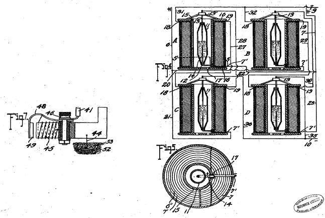
Abstract ~ Vapour apparatus, arrangements of. - A rectifier for use with apparatus for producing electricity from the earth consists of mercury- vapour lamps constructed and arranged as shown in Fig. 4. Each lamp comprises two wires 6<1>, 7<1> wound around a steel tube 15 surrounding a mercury tube 11 preferably of copper. The coil 6<1> is connected between the electrode 14 and the terminal 18, and the coil 7<1> between the terminals 19, 5. The coils 6<1>, 7<1> are preferably composed of soft iron. Reference has been directed by the Comp- troller to Specifications 16,709/87, 14,033/99, and 5457/11, [all in Class 53, Galvanic batteries], and 15,412/06.
This invention relates to improvements in apparatus for the production of electrical currents, and the primary object in view is the production of a commercially serviceable electrical current without the employment of mechanical or chemical action. To this end the invention comprises means for producing what I believe to be dynamic electricity from the earth and its ambient elements.
I am, of course aware that it has been proposed to obtain static charges from upper strata of the atmosphere, but such charges are recognized as of widely variant potential and have thus far proved of no practical commercial value, and the present invention is distinguished from all such apparatus as has heretofore been employed for attracting static charges by the fact that this improved apparatus is not designed or employed to produce or generate irregular, fluctuating or other electrical charges which lack constancy, but on the other hand I have by actual test been able to produce from a very small apparatus at comparatively low elevation, say about 50 or 60 feet above the earth’s surface, a substantially constant current at a commercially usable voltage and amperage. This current I ascertained by repeated tests is capable of being readily increased by additions of the unit elements in the apparatus hereinafter set forth, and I am convinced from the constancy of the current obtained and its comparatively low potential that the current is dynamic and not static, although, of course, it is not impossible that certain static discharges occur and, in fact, I have found occasion to provide against the damage which might result from such discharge by the provision of lightning arresters and cut-out apparatus which assist in rendering the obtained current stable by eliminating sudden fluctuations which sometimes occur during conditions of high humidity from what I consider static discharges. The nature of my invention is obviously such that I have been unable to establish authoritatively all of the principles involved, and some of the theories herein expressed may possibly prove erroneous, but I do know and am able to demonstrate that the apparatus which I have discovered does produce, generate, or otherwise acquire a difference of potential representing a current amperage above stated, or varied therefrom at the will of the operator according to the uses which the current is to be subjected.
The invention comprises generically means for producing electrical currents of serviceable potential substantially without the employment of mechanical or chemical action, and in this connection I have been able to observe no chemical action whatever on the parts utilized although deterioration may possibly occur in some of the parts, but so far as I am able to determine such deterioration does not add to the current supply but is merely incidental to the effect of climatic action.
The invention more specifically comprises the employment of a magnet or magnets and a co-operating element, such as zinc disposed adjacent to the magnet or magnets and connected in such manner and arranged relative to the earth so as to produce current, my observation being that current is produced only when such magnets have their poles facing substantially to the north and south and the zincs are disposed substantially along the magnets.
The invention also comprehends other details of construction, combinations and arrangements of parts as will hereinafter be fully set forth and claimed.
In the accompanying drawings:
Figure 1 is a top plan view of an apparatus embodying the features of the present invention, the arrow accompanying the figure indicating substantially the geographical north, parts of the figure being diagrammatic for condensing the showing.

Figure 2 is a view is side elevation of the parts seen in plan in Figure 1.

Figure 3 is a vertical section taken on the plane indicated by the line 3-3 of Figure 2 and looking in the direction indicated by the arrow.

Figure 4 is a detail view partly in elevation and partly in section showing the detail connections of the converter and intensifier.

Figure 5 is a transverse section taken on the planes indicated by line 5-5 of Figure 4 and looking downwardly.

Figure 6 is an enlarged detail fragmentary section illustrating the parts at the juncture of the conductors and one of the intensifiers.

Figure 7 is an enlarged detail view partly in elevation and partly in section of one of the automatic cut-outs and

Figure 8 is a diagrammatic view of one of the simplest forms of embodiment of the invention.

Referring to the drawing by numerals, 1,1 indicates magnets connected by a magnetic substance 2, preferably an iron wire. The magnets 1 are arranged in pairs, one pair being spaced beneath the other, and interposed between the magnets are zinc plates 3,3 connected by an iron wire conductor 4. Suitable insulating supports 5 are arranged for sustaining the respective magnets 1 and plates 3,3. Each plate 3 is preferably bent substantially into V form, as clearly seen in Figure 1, and the V1 of one of the plates opens or faces toward the north and the V of the other plate to the South. I have determined by experimentation that it is essential that the plates 3 be disposed substantially north and south with their flat faces approximately parallel to the adjacent faces of the co-operating magnets, although by experience I have not discovered any material difference in the current obtained when the plates are disposed slightly to one side of north and south, as for instance when the plates are disposed slightly to one side of north and south, as for instance when disposed in the line of the magnetic polarity of the earth. The same is true with respect to the magnets 1, the said magnets being disposed substantially north and south for operative purposes, although I find that it is immaterial whether the north pole of one of the magnets is disposed to the north and the south pole to the south, or vice versa, and it is my conviction from experience that it is essential to have the magnets of each pair connected by magnetic material so that the magnets substantially become one with a pole exposed to the north and a pole exposed to the north. In Figure 1, I have indicated in full lines by the letters 8 and N the respective polarities of the magnets 1, and have indicated in dotted lines the other pole of those magnets when the connection 2 is severed. I have found that the magnets and zinc plates operate to produce, whether by collection or generation I am not certain, electrical currents when disposed substantially north and south, but when disposed substantially east and west no such currents are produced. I also find that the question of elevation is by no means vital, but it is true that more efficient results are obtained by placing the zincs and magnets on elevated supports. I furthermore find from tests that it is possible to obtain currents from the apparatus with the zincs and magnets disposed in a building or otherwise enclosed, although more efficient results are obtained by having the said elements arranged in the open.
While in Figures 1, 2, and 3, I have shown the magnets and the zinc plates as superimposed, it will be apparent, as hereinafter fully set forth, that these elements may be juxtaposed in horizontal planes, and substantially the same results will be secured. Furthermore, the magnets 1 with the interposed zincs 3, as shown in Figures 1, 2 and 3 merely represent a unit which may be repeated either horizontally or vertically for increasing the current supply, and when the unit is repeated the zinc plates are arranged alternating with the magnets throughout the entire series as hereinafter indicated.
A conductor 6 is connected in multiple with the conductors 2 and a conductor 7 is connected with conductor 4, the conductor 6 extending to one terminal of a rectifier which I have indicated by the general reference character 8, and the conductor 7 extending to the other terminal of said rectifier. The rectifier as seen in diagram in Figure 1 may assume any of several well known embodiments of the electrical valve type and may consist of four asymmetric cells or Cooper-Hewitt mercury vapor lamps connected as indicated in Figure 1 for permitting communication of the positive impulses from the conductor 6 only to the line conductor 9 and the negative impulses from conductor 6 on only to the line conductor 10. The current from this rectifier may be delivered through the conductors 9 and 10 to any suitable source for consumption.
While the said rectifier 8 may consist of any of the known types, as above outlined, it preferably consists of a specially constructed rectifier which also has the capacity of intensifying the current and comprises specifically the elements shown in detail in Figures 4, 5, and 6 wherein I have disclosed the detail wiring of the rectifier when composed of four of the rectifying and intensify in elements instead of asymmetric cells or simple mercury vapor valves. As each of these structures is an exact embodiment of all the others, one only will be described, and the description will apply to all. The rectifying element of each construction consists of a mercury tube 11 which is preferably formed of glass or other suitable material, and comprises a cylinder having its end portions tapered and each terminating in an insulating plug or stopper 12. Through the upper stopper 12 is extended the electrode 13 which extends well into the tube and preferably substantially one-half the length thereof to a point adjacent the inner end of an opposing electrode 14 which latter electrode extends thence downwardly through the insulation 12 at the lower end of the tube. The tube 11 is supplied with mercury and is adapted to operate on the principle of the mercury vapor lamp, serving to rectify current by checking back impulses of one sign and permitting passage of impulses of the other. To avoid the necessity for utilizing a starter, as is common with the lamp type of electrical valve, the supply of mercury within the tube may be sufficient to contact with the lower end of the electrode 13 when current is not being supplied, so that as soon as current is passed from one electrode to the other sufficiently for volatilizing that portion of the mercury immediately adjacent the lower end of electrode 13, the structure begins its operation as a rectifier. The tube 11 is surrounded by a tube 15 which is preferably spaced from tube 11 sufficiently for allowing atmospheric or other cooling circulation to pass the tube 11. In some instances, it may be desirable to cool the tube 11 by a surrounding body of liquid, as hereinafter indicated. The tube 15 may be of insulating material but I find efficient results attained by the employment of a steel tube, and fixed to the ends of the of the tube are insulating disks 16, 16 forming a spool on which are wound twin wires 6^1 and 7^1, the wire 6^1 being connected at the inner helix of the coil with the outer end of the electrode 14, the lower portion of said electrode being extended to one side of the tube 11 and passed through an insulating sleeve 17 extending through the tube 15, and at its outer end merging into the adjacent end of the wire 6^1. The wire 7^1 extends directly from the outer portion of the spool through the several helices to a point adjacent the juncture of the electrode 14 with wire 6^1 and thence extends in mechanical parallelism with the wire throughout the coil, the wire 6^1 ending in a terminal 18 and the wire 7^1 ending in a terminal 19. For the sake of convenience of description and of tracing the circuits, each of the apparatus just above described and herein known as an intensifier and rectifier will be mentioned as A, B, C and D, respectively. Conductor 6 is formed with branches 20 and 21 and conductor 7 is formed with similar branches 22 and 23. Branch 20 from conductor 6 connects with conductor 7^1 of intensifier B and branch 21 of conductor 6 connects with the conductor 7^1 of intensifier C, while branch 22 of conductor 7 of intensifier C, while branch 22 of conductor 7 connects with conductor 7^1 of intensifier D. A conductor 27 is connected with terminal 19 of intensifier A and extends to and is connected with the terminal 18 of intensifier C, and a conductor 7 connects with conductor 7^1 of intensifier D. A conductor 27 is connected with terminal 19 of intensifier A. and extends to and is connected with terminal 18 of intensifier C, and a conductor 28 is connected with the terminal 19 of intensifier C and extends from the terminal 19 of intensifier B to the terminal 18 of intensifier D to electrode 13 of intensifier B. Each electrode 13 is supported on a spider 13^1 resting on the upper disk 16 of the respective intensifier. Conductors 31 and 32 are connected with the terminals 18 of intensifiers A and B and are united to form the positive line wire 9 which co-operates with the negative line wire 10 and extends to any suitable point of consumption. The line wire 10 is provided with branches 35 and 36 extending to the electrodes 13 of intensifiers C and D for completing the negative side of the circuit.
Thus it will be seen that alternating currents produced in the wires 6 and 7 will be rectified and delivered in the form of a direct current through the line wires 9 and 10, and I find by experiment that the wires 6 and 7 should be of iron, preferably soft, and may of course be insulated, the other wiring not specified as iron being of copper or other suitable material.
In carrying out the operation as stated, the circuits may be traced as follows: A positive impulse starting at the zincs 3 is directed along conductor 7 to branch 23 to conductor 7^1 and the winding of the rectifier of intensifier B through said rectifier to the conductor 6^1, through the winding thereof to the contact 18, conductor 32 and to the line wire 9. The next or negative impulse directed along conductor 7 cannot find its way along branch 23 and the circuit just above traced because it cannot pass across the rectifier of intensifier B but instead the negative impulse passes along conductor 22 to conductor 7 of intensifier A and the winding thereof to the contact 19 and to conductor 27 to contact 18 of intensifier C, to the winding of the wire 6^1 thereof to the electrode 14 through the rectifier to the of the electrode 13 and conductor of intensifier A, electrode 14 thereof and conductor 6^1 to contact 18 and wire 31 to line wire 9. Obviously the positive impulse cannot pass along the wire 20 because of its inverse approach to the rectifier of intensifier B. The next impulse or negative impulse delivered to conductor 6 cannot pass along conductor 21 because of its connection with electrode 13 of the rectifier of intensifier A, but instead passes along conductor 20 to the wire 7^1 and its winding forming part of intensifier B to the contact 19 and conductor 29 to contact 18 and the winding of wire 6^1 of intensifier D to the electrode 14 and through the rectifier to the electrode 13 and conductor 35 to line wire 10. Thus the current is rectified and all positive impulses directed along one line and all negative impulses along the other lie s that the potential difference between the two lines will be maximum for the given current of the alternating circuit. It is, of course, apparent that a less number of intensifiers with their accompanying rectifier elements may be employed with a sacrifice of the impulses which are checked back from a lack of ability to pass the respective rectifier elements, and in fact I have secured efficient results by the use of a single intensifier with its rectifier elements, as hereinafter set forth.
Grounding conductors 37 and 38 are connected respectively with the conductors 6 and 7 and are provided with the ordinary lightning arresters 39 and 40 respectively for protecting the circuit against high tension static charges.
Conductors 41 and 42 are connected respectively with the conductors 6 and 7 and each connects with an automatic cutout 43 which is grounded as at 4. Each of said automatic cutouts is exactly like the other and one of the same is shown in detail in Figure 7 and comprises the inductive resistance 45 provided with an insulated binding post 46 wit which the respective conductor 6 or 7 is connected, said post also supporting a spring 48 which sustains an armature 49 adjacent to the core of the resistance 45. The helix of resistance 45 is connected preferably through the spring to the binding post at one end and at the other end is grounded on the core of the resistance, the said core being grounded by ground conductor 44 which extends to the metallic plate 52 embedded in moist carbon or other inductive material buried in the earth. Each of the conductors 41, 42 and 44 is of iron, and in this connection I wish it understood that where I state the specific substance I am able to verify the accuracy of the statement by the results of tests which I have made, but of course I wish to include along with such substances al equivalents, as for instance, where iron is mentioned its byproducts, such as steel, and its equivalents such as nickel and other magnetic substances are intended to be comprehended. The cutout apparatus seen in detail in Figure 7 is employed particularly for insuring against high tension currents, it being obvious from the structure shown that when potential rises beyond the limit established by the tension of the spring sustaining the armature 40, the armature will be moved to a position contacting with the core of the cutout device and thereby directly close the ground connection for line wire 41 with conductor 44, eliminating the resistance of winding 45 and allowing the high tension current to be discharged to the ground. Immediately upon such discharge the winding 45 losing its current will allow the core to become demagnetized and release the armature 49 whereby the ground connection is substantially broken leaving only the connection through the winding 45 the resistance of which is sufficient for insuring against loss of low tension current.
In Figure 8 I have illustrated an apparatus which though apparently primitive in construction and arrangement comprehends the first successful embodiment which I produced in the course of discovery of the present invention, and it will be observed that the essential features of the invention are therein disclosed. The structure delineated in said figure consists of horseshoe magnets 54, 55, one facing north and the other south, that is, each opening in the respective directions indicated and the two being connected by an iron wire 55 which is uninsulated and wrapped about the respective magnets each end portion of the wire 55 being extended from the respective magnets to and connected with, as by being soldered to, a zinc plate 56, there being a plate 56 for each magnet and each plate being arranged longitudinally substantially parallel with the legs of the magnet and with the faces of the plate exposed toward the respective legs of the magnet, the plate being thus arranged endwise toward the north and south. An iron wire 57 connects the plates 56, the ends of the wire being preferably connected adjacent the outer ends of the plates but from experiment I find that the wire may be connected at practically any point to the plate. Lead wires 58 and 59 are connected respectively with the wires 55 and 57 and supply an alternating current at a comparatively low tension, and to control such current the wires 58 and 59 may be extended to a rectifier or combined rectifier and intensifier, as above set forth.
The tests which I have found successful with the apparatus seen in Figure 8 were carried out by the employment first of horseshoe magnets approximately 4 inches in length, the bar comprising the horseshoe being about one inch square, the zincs being dimensioned proportionately and from this apparatus with the employment of a single intensifier and rectifier, as above stated, I was able to obtain a constant current of 8 volts.
It should be obvious that the magnets forming one of the electrodes of this apparatus may be permanent or may be electromagnets, or a combination of the two.
While the magnets mentioned throughout the above may be formed of any magnetic substance, I find the best results obtained by the employment of the nickel chrome steel.
While the successful operation of the various devices which I have constructed embodying the present invention have not enabled me to arrive definitely and positively at fixed conclusion relative to the principles and theories of operation and the source from which current is supplied, I wish it to be understood that I consider myself as the first inventor of the general type hereinbefore described capable of producing commercially serviceable electricity, for which reason my claims hereinafter appended contemplate that I may utilize a wide range of equivalents so far as concerns details of construction suggested as preferably employed.
The current which I am able to obtain is dynamic in the sense that it is not static and its production is accomplished without chemical or mechanical action either incident to the actual chemical or mechanical motion or incident to changing caloric conditions so that the elimination of necessity for the use of chemical or mechanical action is to be considered as including the elimination of the necessity for the use of heat or varying degrees thereof.
Having now particularly described and ascertained the nature of my said invention, and in what manner the same is to be performed, I declare that what I claim is: --- [Claims not included here]
From the Article in Tech. World Mag.:
1. First demo model
was powerful enough to spark a gas engine.
2. Second model developed 8 volts.
3. Demo model at Patent Office was elevated on short poles.
4. The model planned to power Phoenix AZ would be elevated 200
feet.
5. The Absorber "consists of a series of magnetized steel
plates set in a circle (the manner of preparing them is kept
secret)".
6. "[T]he magnetizing of one set of plates... is part of the
secret of the treatment which makes it respond to the
accumulations of the atmosphere".
From British Patent # 1098 (1913):
"I have been able... to produce from a very small apparatus at comparatively low elevation, say about 50 or 60 feet above the earth’s surface, a substantially constant current at a commercially useable voltage and amperage".
"This current... is capable of being readily increased by additions of the unit elements in the apparatus".
Fig. 1 and Fig. 2 show the magnet poles are connected N-S by a thick iron rod (thick compared to the lines used for wires in the drawings).
No angle is specified for the V-shaped zinc plates. The article (but not the patent) states that the plates are magnetized (obviously not zinc). Zinc-galvanized steel? Will a thin film of Zn work? Or, powdered Zn in a binder (more surface area)? Or, zinc-galvanized iron wire in a coil?
The Palmer Craig device ( www.rexresearch.com/craig/craig.htm ) is powered by the terrestrial magnetic field, and employs a thin film of bismuth to capture the energy as diamagnetism. Perhaps this can be integrated with Meyers’ device.
Figure 8 (the demonstration of principle) show uninsulated iron wire being used to connect the plates and magnets. The wire is wound around the Bloch wall area of the horseshoe magnets. Perhaps Coler-type windings around the poles could be used here ( See: www.rexresearch.com/coler/coler.htm ). Coler used copper plates as "condensers" in his device. Could copper plates be used for the Meyers device? Perhaps flat (Tesla non-inductive) coils could be integrated here.
"It is essential that the plates 3 be disposed substantially N and S with their flat faces approximately parallel to the adjacent faces of the co-operating magnets....
"I find that it is immaterial whether the N pole of one of the magnets is disposed to the N and the S pole to the S, or vice versa".
"[T]he magnets and zinc plates... produce electrical currents when disposed... N and S, but when disposed... E and W no such currents are produced".
"[E]levation is by no means vital, but... more efficient results are obtained by placing the zincs and magnets on elevated supports".
"The elements may be disposed in horizontal planes [or vertically]...".
The "zinc plate 56... [is] arranged longitudinally substantially parallel with the legs of the magnet and with the faces of the plate exposed toward the respective legs of the magnet, the plate being thus arranged endwise toward the north and south".
The first model used "horseshoe magnets approximately 4 inches in length, the bar comprising the horseshoe being about one inch square, the zincs being dimensioned proportionately and from this apparatus with the employment of a single intensifier and rectifier, as above stated, I was able to obtain a constant current of 8 volts... [T]he magnets... may be permanent or may be electromagnets, or a combination of the two... I find the best results obtained by... nickel chrome steel".
Comments & Questions:
The rectifier is described as a preferred embodiment, but other designs also work. The Ed Gray capacitor design comes to mind ( www.rexresearch.com/evgray/1gray.htm ). The Tate Ambient Power Module also might apply ( www.rexresearch/tate/tate.htm ).
Would non-ferrous magnets work? Is there a frequency involved (oscilloscope tests)? Coler found that ferromagnetism has a resonant frequency about 180 KHz. Can the components be made adjustable for RLC-resonance?


Timothy Hughes Rare & Early Newspapers
The front page has one column headlines that include: "MYSTERY OF CENTURIES SOLVED BY CONVICT", "Convinced of Truth of This, the Governor of Arizona Releases Prisoner so May Obtain the Patents", "Collects Electricity From The Atmosphere", and more. This is coverage on the invention by Roy. J. Meyers in which he called the "Absorber".


https://www.findagrave.com/memorial/75421134/roy-jerome-meyers
Roy Jerome Meyers
Birth -- 18 Aug 1879 Iowa, USA
Death -- 5 May 1958 (aged 78) Sacramento County, California, USA
Burial -- Sunset Lawn Chapel of the Chimes Memorial Park Sacramento, Sacramento County, California, USA
Memorial ID 75421134 · View Source
Roy Jerome Meyers was the son of Charles Morton Smith and Alzoa Amy Minkler. He changed his name to Meyers as a young man. He was born in Edgewood, Iowa. His father died when he was 11 and he went to work to support his family. A few years later his sister died. Roy hit the road and made some bad mistakes. He was socially inept and didn't choose good company. But he married a good woman, Carrie Weller, and she stuck with him through thick and thin. He worked hard all his life.
Roy became well known in 1912 as the "convict inventor" and again in 1931-32 as the most highly publicized compressed air car inventor of the 1930s. In 1912 he was befriended by the first governor of the new state of Arizona who gave him a job in a nearby town. The state legislators paid out of their own pockets for him to take his first invention to the patent office in Washington DC.
Roy was a professional machinist, and a self-taught electrician and mechanic. He also worked as a chauffeur. During his life he lived in Northern California, Southern California, New Orleans, Nebraska, and Arizona. He also lived briefly in other places including Alaska, Baltimore, Chicago, and New York City.
Dorothy S (Meyers) Weitz is his daughter. She is buried in Roswell, New Mexico.
His last patent was granted a few weeks after his death. It was for a merry-go-round powered by a teeter-totter.
https://www.douglashistory.co.uk/famgen/getperson.php?personID=I38684&tree=tree1
Roy Jerome Meyers
Roy J Meyers became famous twice in his life for inventions. The first time was 1912 when he cashed a bad check for a friend. While in prison in Arizona, he invented a machine that supposedly absorbed small amounts of electricity from the environment. He was released on his own recognizance to travel to Washington DC to apply for a patent. He was an obsessive, intelligent inventor, but lacked social skills. He was married to a girl from a prominent Southern family who stayed with him through his trials and tribulations. He obtained several US patents and patents from other countries. He was a self-taught electrician, mechanic, and machinist.
He and his wife Carrie had one daughter.
His inventions were featured in magazines such as Popular Science and newspapers across the US reported on his compressed air car. Around 1918(?) he was accused of insurance fraud, in New Orleans, and then later in the early stages of his air car work he was arrested when a financier accused him of making claims he could not back up. Nothing came of this arrest (as far as I know). This sort of things happens to inventors all the time when they get too excited and use someone else's money to "finish" an invention, only to find it is not possible to keep their promises to the financier. History suggests that at around this point he stopped using terms like "perpetual motion" and kept his claims within reason. Learning this lesson must have helped make him the most famous air car inventor of the 1930s.
https://www.theguardian.com/science/2005/mar/31/farout
Science in chains
Mark Pilkington
Wed 30 Mar 2005
America's prisons are a traditional source of cheap labour, churning out blue jeans, licence plates, glasses and cardboard boxes. But, according to a 1912 Technology World magazine article, one prisoner's engineering project at Arizona state penitentiary so impressed his keepers that he was given 30 days' parole to patent it.
Roy J Meyers was serving three and a half years at the time, spring 1912, though the article doesn't say what for. Before his conviction, he had applied for a number of patents, including one for a tram wheel, but his new idea was altogether grander. Called the "Absorber", Meyers' invention would, he claimed, draw energy from the atmosphere and convert it to electricity.
The prison authorities, perhaps hoping they had another Edison or Tesla on their hands, gave Meyers use of a workshop, located just outside the prison walls. Within a few weeks, a demonstration model was igniting gas engines at the prison pump house, followed by a second device, which produced a modest output of eight volts.
A visiting prison reformer, Kate Barnard, suggested that Meyers be granted parole to pursue his work. She took his case to the state governor, who gave him 30 days' leave to bring his project to fruition.
Meyers' first stop was the Patent Office in Washington DC. Already used to grandiose claims from would-be free energy pioneers, it suggested that he returned with a working model. This he did, and so filed an application.
Details are scant, but a photograph of a six-foot model shows a wooden tower, atop which sits the Absorber itself: a ring of specially coated, magnetised steel plates connected to a transformer below. How it worked was a secret, and remains one to this day.
Meyers returned to Florence to serve the last 10 months of his sentence, two days before his allotted time was up. On his release, he told the Technology World article's author, that he planned to build a 200ft Absorber that would provide enough direct current to power the city of Phoenix. And that is where this tantalising story ends.
Did Meyers ever build his full-size Absorber, or was he just another conman or crackpot? Unfortunately, barring a trip to Florence, Arizona and the US Patent Office, we may never find out.