Microwave
Hydrogen Generators
http://emediapress.com/2016/05/12/water-powered-moped/
2016-05-12
WATER
POWERED MOPED?
Aaron Murakami
Aaron Murakami
Makis Triantafillopoulos in Greece claims to have created a moped that runs on water.
He uses milliwatts of RF to separate hydrogen from salt water – this process is reminiscent of the late John Kanzius who was able to “burn” salt water.
This is a Greek website translated into English :
http://translate.google.com/translate?u=http%3A%2F%2Fwww.zougla.gr%2Fgreece%2Farticle%2Fi-kinisi-me-idrogono-apoteli-pragmatikotita&langpair=auto|en&hl=en
The formula to his claim is not revealed as it appears he is waiting for worldwide patent protection.
https://www.youtube.com/watch?v=RDJh2j-Skds
Zougla.gr reportage for the invention of Peter Campus
https://www.youtube.com/watch?v=Z_DmWEQf7_0
New details about his invention presented by physicist Peter Painter [ Campus ], the show "Yellow Press" with Makis Triantafillopoulos presence of scientists and specialists.
https://www.youtube.com/watch?v=rA7UseeKEvM
P. Painter [ Campus ] produces electricity from water. The patent yiothetithike the MoD
https://www.youtube.com/watch?v=kRwfx2Ktzx8
Special scientific conference for the invention of Peter Campus
https://www.youtube.com/watch?v=TaPonbPUQ_I
Live hydrogen production demonstration to show Yellow Type
http://www.zougla.gr/greece/article/i-kinisi-me-idrogono-apoteli-pragmatikotita
A new application of the inventor Peter Campus hydrogen technology was presented Thursday to show "Yellow Press" Makis Triantafillopoulos.
Breaking with innovative, direct and inexpensive way plain water into its components, using a device small, produced hydrogen that with appropriate -aples- conversions, can replace the known gasoline engine and operate the vehicle engines.
The presentation of this application was made Thursday morning at Salamis, with the TV crew of zougla.gr record from the first moment all conversion processes of a vehicle capacity of 50 ml to move to hydrogen energy.
Revving ... the tank with water to feed the engine with hydrogen
Mr. Painter launched the device and then the low cylinder capacity motorcycles which traveled 10 km by consuming hydrogen, ie essentially ... plain water!
Easily perceived the huge importance of this invention, in a simple manner and appropriate adjustments can be fitted to any vehicle holistically changing the way the economy and societies around the world.
"No one can stop the spread of this invention," said Makis Triandafyllopoulos, to scientists who framed the emission panels to cheer recognizing the importance and impact that may have the apparatus of Peter Campus.
While extensively discussed all the details surrounding the groundbreaking experiment scientists to submit their views on the great Greek invention.
The development of the invention for a few weeks is done with the cooperation and under the protection of the Ministry of Defense.

\

GR1007830
METHOD AND DEVICE FOR WATER ELECTROLYSIS AND PRODUCTION OF HYDROGEN TO BE USED AS COMBUSTIBLE UPON UTILISATION OF COMBINED FREQUENCIES
METHOD AND DEVICE FOR WATER ELECTROLYSIS AND PRODUCTION OF HYDROGEN TO BE USED AS COMBUSTIBLE UPON UTILISATION OF COMBINED FREQUENCIES
Inventor: ZOGRAFOS PETROS EVANGELOU, SPILIOPOULOS IOANNIS DIMITRIOU
Novelty: There are disclosed a method and a device destined for water electrolysis and production of hydrogen to be used as combustible by combination of high frequencies produced by semitonic oscillators; when mixed, reinforced and combined, said frequencies contrive to break water into its elements (hydrogen and oxygen) upon influence of the coordination effect. Secondary frequencies configurating the structure of the primary frequencies for obtaining adequately-combined frequencies by means of the respective electronic circuit composed of an isolator, a mixer, a directional coupler, a multiplier, configurators, digital frequency controllers, and linear amplifiers can be introduced with the assistance of adequate main and auxiliary treatment equipments into the primary frequencies produced by the semitonic oscillators. The vibration of water molecules and the breaking thereof into hydrogen and oxygen are obtained by suitably-coordinated frequencies. The gases are, thereafter, separated by special sorting guides while the producing hydrogen.

http://chemistry.stackexchange.com/questions/8642/how-does-high-frequency-water-electrolysis-work
How
Does High Frequency Electrolysis Work ?
"I found a bunch of nonsense claims in the internet, about the resonance frequency of water helping to split bonds.
The first thing to realize here is that there is no one resonance frequency of water. With suitable energy, you can excite rotational, vibrational and electronic states (I left out translation - there transition energies minute). At room temperature you can say as a rule of thumb that most molecules will be in some excited rotational state, but in the vibrational and electronic ground states. Excitation energies for rotation are in the far infrared or microwave energy/frequency region. Widely used e.g. in the microwave oven at 2.45 GHz (≈ 12 cm). Actually, the whole region is full of bands where water absorbs. Note that microwave heating of water does not cause electrolysis. Vibrational transitions are around 2.9 μm = 105 THz = 3500 cm⁻¹ and 6μm = 50 THz = 1635 cm⁻¹ with lots of combinations and overtones throughout the near infrared region. Quite exceptionally, the visible region is basically free of water absorption. Electronic transitions (breaking of bonds) need energies in the UV, and here we meet bands that lead to photodissociation, e.g. at 166nm (taken from Wikipedia). That corresponds to 1.8 PHz = 1.8⋅1015 Hz. Compare this to the kHz and MHz where your link claims dissociation.
This doesn't mean that the pulsed DC cannot help, nor that impedance spectroscopy won't give important information. But resonance frequencies in the kHz range are electrical LC-circuit resonances depending on cell and electrode geometries and electrical double layers etc. But neither on vibrations nor breaking of the bonds of the water molecule.
To give the "method" you ask about some real world numbers, at the very end of the Wiki page the energy efficiency for industrial water electrolysis is cited as usually between 50 and 80 %.
The paper then proposes to burn the gas in an internal combustion machine. As such a stationary process could be adjusted so that the engine is at its maximum efficiency, we may assume 1/3 or 35% efficiency here.
We then need a generator to convert the mechanical energy into electric energy. Fortunately, that step is rather efficient. Say, 95 %.
A fuel cell would be more efficient than the combustion - generator combination: ca. 40 - 60 % according to Wikipedia.
Unfortunately, also battery charging is not 100% efficient. Let's assume 80–90% (taken from Wikipedia on Li-ion batteries) For batteries that are charged with higher current (or current density) efficiency is less. Example would be lead-acid batteries as used in cars. Wiki quotes efficiencies between 50 and 80 %.
Taking these numbers together, I conclude that after going once through the cycle of the proposed "perpetuum mobile", 8 - 24 % of the energy are retained in a "useful state" while 76 - 92 % became heat. With fuel cell, we may be able to "boost" the energy efficiency to 43%...
Resonant
Frequencies of Water
http://www.schoolphysics.co.uk/age16-19/Wave%2520properties/Wave%20properties/text/Microwave_ovens/index.html
Microwave ovens operate at a frequency of 2.45 GHz (2.45x10⁹ Hz) and this is NOT the resonant frequency of a water molecule…
Water and microwaves
Water molecules contain three atoms and so can vibrate in a number of different ways. This makes calculating their resonant frequency very difficult. However microwave radiation of any frequency will affect them although they may not resonate.
Some vibrations of a three atom molecules are shown in the diagram. They are not to scale and are only meant to represent possible states of vibration.
When microwaves pass through water the water molecules absorb some of the microwave energy and as a result they twist and turn, writhing around, as the radiation passes by. However after the microwaves have gone the molecules stop moving again, remitting the energy as more microwaves. In free water molecules this does not result in a heating.
In a liquid things are rather different. The water molecules are close to reach other and so there is "friction" between them. It is the rubbing of one molecule against another as in liquid water that allows the energy to be retained and prevents it being reemitted as microwaves. The "friction" between the writhing water molecules and other molecules in a solid also heats up the solid.
Microwave ovens operate at a frequency of 2.45 GHz (2.45x10⁹ Hz) and this is NOT the resonant frequency of a water molecule. This frequency is much lower than the diatomic molecule resonant frequencies mentioned earlier. If 2.45 GHz were the resonant frequency of water molecules the microwaves would all be absorbed in the surface layer of a substance (liquid water or food) and so the interior of the food would not get cooked at all.
The 2.45 GHz is a kind of useful average frequency. If the frequency was much higher then the waves would penetrate less well, lower frequencies would penetrate better but are absorbed only weakly and so once again the food would not absorb enough energy to cook well.
Standing waves set up within the oven. A standing wave is formed whenever two waves travelling in opposite directions meet in a "restricted area". This restricted area could be a metal box (as in a microwave oven) or a stretched string as in a violin.
Microwave ovens cook unevenly because a pattern of standing waves forms inside the oven chamber, and the pattern creates an array of hotspots throughout the oven's volume. An operating frequency of 2.45 GHz will produce a wavelength of around 12.25 cm, and the regions of maximum intensity (hotspots) will be at half-wave points, or every 6.125 cm, but in a complex 3D pattern.
This standing wave pattern explains why microwave ovens only work effectively if the food is rotated through the standing waves and why some ovens actually move the pattern by rotating the transmitter.
http://www.colorado.edu/physics/2000/applets/h2o.html
Water
Molecule in a Microwave Field
Adjust the power of the microwave field to see how it affects the water molecule.
Zoom in and out with the zoom slider.
http://www1.lsbu.ac.uk/water/water_vibrational_spectrum.html
Water
Absorption Spectrum
Water absorbs a wide range of electromagnetic radiation with rotational transitions and intermolecular vibrations responsible for absorption in the microwave (~1 mm - 10 cm wavelength) and far-infrared (~10 µ - 1 mm), intramolecular vibrational transitions in the infrared (~1 µ- 10 µ) and electronic transitions occurring in the ultraviolet region (< 200 nm)
http://physics.stackexchange.com/questions/169173/what-is-the-resonant-frequency-of-liquid-water
What
is the resonant frequency of liquid water?
The lowest resonance of the water molecule is 22.235 GHz. This frequency is almost 10 times higher than the operating frequency of the microwave oven (2.45 GHz)…
What is important in the idea of resonance with water is to establish a frequency of excitation that causes the natural frequencies to superimpose or wave superposition. By achieving wave superposition the amplitude of the oscillations will have the greatest potential of breaking the molecule into its elemental constituents thereby creating free atoms that can recombine to form the diatomic molecules desired. H2 and O2 Oddly enough chemistry and properties of elements can play into this process as the electrodes used if they are constructed of platinum will result in a better yield from hydrolysis. This may be the result of how the atomic structure of platinum releases electrons through solution. A similar process has been observed in certain solar cells as alloys of atoms are placed on layers of silicon substrate creating a resonant cavity to enhance voltage production through the capture of photons. The explanation comes from the energy level of exchange of electrons during enthalpy processes that exceed the enthalpy energy required to break the covalent bonds of H2O…
http://www.experienceproject.com/question-answer/What-Frequency-Does-Water-Resonate-At-Pleae-Dont-Say-24GHz--In-A-Microwave-They-Jst-Vibrate-At-That-Frequenc/13329
It's quite easy... Most high power SONAR systems can do it. Cavitation was always a concern of the higher power SONAR heads. Things that could do 230-235 dB at 38 to 50 kHz. Even higher, further up in frequency. And could be done with just 300-500W of power.
Look for info on SONAR head design. However, if you're looking to do it for energy generation via release of hydrogen, it's terribly inefficient. It'll take A few hundred Watts to get a few Watts of hydrogen...
It's 42 kHz which can be be achieved by either ultrasound or radiowaves or both but because you need pure water to split it at this frequency so it's kinda impractical - tho if you vibrate water at this frequency it makes standard electrolysis more efficient - several designs to do this exist in the literature
http://overunity.com/8788/frequencies-and-resonance/#.VzpZT4U9ByQ
A high amplitude transmitter signal of 1420405751.768 Hz(1420 Mhz UHF) should cause Saltwater to spontaneously ignite, 1420MHz is the hyperfine resonate frequency of Hydrogen Plasma and the focused transmitted signal should directly interact with Hydrogen Molecules.
I don't know what frequency this gentleman [ Kanzius ] is using but near the end of the video he shows the theory.
http://www.youtube.com/watch?v=aGg0ATfoBgo
1420 MHz should be the optimum frequency to make it as efficient that it can be for Hydrogen.
http://www.keelynet.com/energy/docx.htm
Verification
of Frequency to produce Etheric Force from Water
A recent (1965) possible verification of the frequency Keely used to dissociate water into etheric force was related to me by a scientist when we were discussing certain aspects of free energy. He wishes to remain anonymous for obvious reasons, but his name is on file. I have no other verification of this experiment, however I believe it merits telling.
The scientist, I shall call him Dr. X, was doing experiments with ultrasonic sound in a column of water. The object of the experiments was to devise a means of separating various densities of materials by injecting them into a column of water which was subjected to an ultrasonic standing wave vibration. The experimental setup is sketched in Figure 3-3 (for BBS considerations a description follows).
A Barium Titanate ultrasonic transducer was fixed to the bottom of a quartz tube which was closed at the bottom and open at the top. Pure water was poured into the tube and the water column was "tuned" so that a standing wave was produced at 40,000 CPS (cycles per second). The transducer was powered by a 700 Watt power amplifier which was driven by an ultrasonic frequency generator.
Because of the large amount of power put into the column of water a certain amount of evaporation took place at a constant rate when the transducer was energized. Therefore, to maintain a standing wave in the water column a feedback device caused the frequency to be raised as the water evaporated and the temperature changed.
As a test, Dr. X decided to run through the experiment with only water in the tube to insure that a standing wave was maintained as the water evaporated and the frequency rose higher and higher. When the experiment was started everything worked beautifully.
Dr. X took periodic readings of his instrumentation and was assured that the standing wave was being maintained. Suddenly, with no warning whatever the water disappeared from the open quartz tube. He looked up thinking to see the water splashed on the ceiling when to his amazement a clean hole went right through the ceiling. The hole was the same size as the inside of the quartz tube.
Further investigation showed the hole continued on through the roof also! Dr. X checked his notebook and found the last frequency entry to be 41,300 CPS. It was shortly after this that the water disappeared.
Because of the time interval between the last reading and the disappearing water, the frequency sent to the transducer was higher than the last reading and Dr. X said it could well have been very close to 42,800 CPS, the Keely dissociation frequency. (11)
This obviously dangerous event caused Dr. X to dismantle the equipment and try some other approach to his problem. This experiment points the way to the use of our modern technology in conjunction with Keely's laws of dissociation to change matter into energy without the use of radioactive materials or extremely expensive atomic accelerators…
Recently we learned that the Water Disrupting Spark Plug promoted around 1994 by Stan Meyers was in fact suggested to him by Dale Pond at a conference in Switzerland back in 1989. The idea was you should be able to use Keely's 42.8khz emitted from a spark plug to instantly dissociate the water molecule to hydrogen and oxygen which would then be exploded to drive the piston.
Meyer took this idea, claimed it as his own and never credited Dale with the idea. He cannot patent it because it was disclosed in a public place in the presence of witnesses. Needless to say, like all of Meyer's other claims, nothing has come of it.
KANZIUS,
John : Salt-Water Fuel
https://www.youtube.com/watch?v=p8xYUDiSGDk
Water
as Fuel Unlocked by Frequency Resonance
Water's oxygen hydrogen bonds can be broken in many ways resulting in high energy outputs that are stored in water. Since water contains an enormous amount of energy, the potentials are endless. This video demonstrates a single method of water bond breaking using radio frequency.
http://www.wpbf.com/news/13383827/detail.html
http://www.wpbf.com/health/11125485/detail.html
Video: http://www.wpbf.com/video/13382787/index.html
Fla.
Man Invents Machine To Turn Water Into Fire
SANIBEL ISLAND, Fla. -- A Florida man may have accidentally invented a machine that could solve the gasoline and energy crisis plaguing the U.S., WPBF News 25 reported.
Sanibel Island resident John Kanzius is a former broadcast executive from Pennsylvania who wondered if his background in physics and radio could come in handy in treating the disease from which he suffers: cancer.
Kanzius, 63, invented a machine that emits radio waves in an attempt to kill cancerous cells while leaving normal cells intact. While testing his machine, he noticed that his invention had other unexpected abilities.
Filling a test tube with salt water from a canal in his back yard, Kanzius placed the tube and a paper towel in the machine and turned it on. Suddenly, the paper towel ignited, lighting up the tube like it was a wax candle.
"Pretty neat, huh?" Kanzius asked WPBF's Jon Shainman.
Kanzius performed the experiment without the paper towel and got the same result -- the saltwater was actually burning.
The former broadcasting executive said he showed the experiment to a handful of scientists across the country who claim they are baffled at watching salt water ignite.
Kanzius said the flame created from his machine reaches a temperature of around 3,000 degrees Farenheit. He said a chemist told him that the immense heat created from the machine breaks down the hydrogen-oxygen bond in the water, igniting the hydrogen.
"You could take plain salt water out of the sea, put it in containers and produce a violent flame that could heat generators that make electricity, or provide other forms of energy," Kanzius said.
He said engineers are currently experimenting with him in Erie, Pa. in an attempt to harness the energy. They've built an engine that, when placed on top of the flame, chugged along for two minutes, Kanzius told WPBF.
Kanzius admits all the excitement surrounding a new possible energy source was a stroke of luck. Someone who witnessed his work on the cancer front asked him if perhaps the machine could be used for desalinization.
"This was an experiment to see if I could heat salt water, and instead of heat, I got fire," Kanzius said.
Kanzius said he hoped that his invention could one day solve a lot of the world's energy problems.
"If I were to be bold enough, I think one day you could power an automobile with this, eventually," Kanzius told WPBF.


WSEE-TV
http://www.goerie.com/apps/pbcs.dll/article?AID=/20070518/WSEE01/70517027/-1
VIDEO : http://interface.audiovideoweb.com/lnk/va92win15111/CURRAN051707.wmv/play.asx
May 18. 2007
KANZIUS
DISCOVERS ALTERNATIVE FUEL
John Kanzius may have found a cure for cancer and a renewable energy source too…
John Kanzius may have found a cure for cancer and a renewable energy source too…
MX2009005080
RF SYSTEMS AND METHODS FOR PROCESSING SALT WATER
Inventor: KANZIUS JOHN [US] ; RUSTUM ROY
Also published as: WO2008064002 // JP2010509565 // EP2109500 // CA2669709
Abstract -- Systems and methods for processing salt water and/or solutions containing salt water with RF energy. Exemplary systems and methods may use RF energy to combust salt water, produce hydrogen from salt water or solutions containing salt water, to volatilize a secondary fuel present in solutions containing salt water, to produce and combust hydrogen obtained from salt water or solutions containing salt water, to volatilize and combust secondary fuel sources present in solutions containing salt water, to desalinate seawater, and to carry out the electrolysis of water are presented. An exemplary system may comprise a reservoir for containing a salt water solution or salt water mixture; a reaction chamber having an inlet and an outlet; a feed line operatively connecting the reservoir to the inlet of the reaction chamber; an RF transmitter having an RF generator in circuit communication with a transmission head, the RF generator capable of generating an RF signal absorbable by the salt water solution or the salt water mixture having a frequency for transmission via the transmission head; and an RF receiver; wherein the reaction chamber is positioned such that it is between the RF transmission head and the RF receiver.


Other patents & applications by John KANZIUS :
US Patent Application # 20060190063
Enhanced Systems and Methods for RF-Induced Hyperthermia
US Patent Application # 20050251234
Systems and Methods for RF-Induced Hyperthermia Using Biological Cells and Nanoparticles as RF Enhancer Carriers
US Patent Application # 20050251233
System and method for RF-induced hyperthermia
US Patent Application # 20050273143
Systems and Methods for Combined RF-Induced Hyperthermia and Radioimmunotherapy
WO2007027620
ENHANCED SYSTEMS AND METHODS FOR RF-INDUCED HYPERTHERMIA II
SYSTEM AND METHOD FOR RF-INDUCED HYPERTHERMIA
WO2005110544
Similar Method & Apparatus Patents --
CN104630814
Automobile water fuel system with high efficiency and low consumption
Automobile water fuel system with high efficiency and low consumption
Inventor(s): ZHOU YANHUI
The invention discloses an automobile water fuel system with high efficiency and low consumption. The system is composed of a high frequency and high voltage power supply, a microwave source and a hydrogen oxygen generator. The high frequency and high voltage power supply comprises a storage battery, a high frequency oscillator and a high voltage coil; the microwave source is composed of a microwave oven magnetron and an assorted circuit; the hydrogen oxygen generator is a reformed miniature water welding machine. The storage battery converts direct current into alternating current through the high frequency oscillator, boosts the alternating current into high frequency and high voltage through the high voltage coil and provides the alternating current to the magnetron; the magnetron generates 2450 MHz microwaves, and the microwaves are introduced into a resonant cavity of the hydrogen oxygen generator to drive water molecules to generate resonance to crack into H<+> and OH<-> ions and generate hydrogen and oxygen under the action of a direct current electric field. A mixed gas with a volume ratio of 2:1 is prepared from the hydrogen and the oxygen by a flow adjusting valve, and the mixed gas is conveyed into an engine compartment for burning to propel a crank shaft to rotate. The system is small in volume, high in efficiency and low in energy consumption, and the gas production speed can satisfy the requirements of the engine, so that the system can be used as the fuel systems of all internal combustion engines.

CN103848397
Hydrogen production device
Hydrogen production device
Inventor(s): WEI WEI
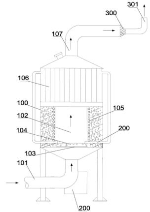
The invention discloses a hydrogen production device which is used for solving a problem that the conventional hydrogen production device is high in hydrogen production cost, and wastes energy resources. The hydrogen production device comprises a reaction furnace, a reaction cavity, a heating device, a steam generator, a gas outlet tube, a microwave plasma generator and a hydrogen ventilating molecular sieve, wherein the reaction furnace comprises a gas inlet tube arranged below the reaction furnace; the reaction cavity is communicated with the gas inlet tube, a reaction sieve and a catalyst arranged on the reaction sieve are arranged in the reaction cavity; the heating device is arranged on the outer part of the reaction cavity; the steam generator is arranged above the reaction furnace and communicated with the reaction cavity; the gas outlet tube which is used for outputting a gas generated in the reaction cavity is communicated with the reaction cavity; the microwave plasma generator is used for enabling a nitrogen gas and an oxygen gas entering from the gas inlet tube in air to be converted into a plasma state, and enabling the nitrogen gas and the oxygen gas in the plasma state to quickly react to generate nitrogen monoxide, arranged at a gas inlet of the gas inlet tube and communicated with the gas inlet tube; and the hydrogen ventilating molecular sieve is used for separating out the hydrogen gas from the gas generated in the reaction cavity. The hydrogen production device disclosed by the invention is low in hydrogen production cost, high in efficiency, energy-saving and environment-friendly.


RO129234
HYDROGEN GENERATOR USING WATER AND SOLID ELECTROLYTE
HYDROGEN GENERATOR USING WATER AND SOLID ELECTROLYTE
Inventor(s): ARGHIRESCU MARIUS, et al.
The invention relates to a hydrogen generator which uses water and a solid electrolyte. According to the invention, the generator comprises an electrolyzer (A) provided with a non-metal support (1) wherein there are fixed a metal body (2) and an electrode-pipe (3) with a water intake nozzle ( c) connected to an electrically operated valve (8) controlled by a level detector (9) and an electrolytic assembly with porous electrodes of sintered metal powder with a catalytic layer, preferably Ni or Ni-Fe, and a medial solid electrolyte (4) arranged as an electrolytic sandwich in the shape of a rosette or a spiral, provided with some spacers (I) as small plates which are heat resistant on one face. Above the electrolytic sandwich there is fixed a selective hydrophobic membrane (6), the created Brown's gas being discharged through a tube (d) of a non-metal cap (5). The electrolyzer (A) also comprises a solenoid winding (7) of a transformer with a primary (e) and a secondary winding (e'), with a rectifying diode and the ends connected to the electrode-pipe (3) and to the body (2), placed either on the metal body (2) or at the bottom of the electrode-pipe (3), which is partially filled with thermally conductive powder (j) for storing thermal energy produced by the induction micro currents generated by the electromagnetic field generated inside the electrolyzer (A) and for producing hot water or steam which passes into the electrolysis space through some orifices ( r) in the electrode-pipe (3). In particular, for steam producing purposes, the electrode-pipe (3) or the metal body (2) has the shape of a microwave guide for a microwave generator (B) of the type of resonant cavity (10) with a magnetron (11), the generated microwaves heating some thermally conductive granules (j') made of porous ceramic or carborundum.

RO128392
HYDROGEN GENERATOR PRODUCING IT FROM WATER, BY MEANS OF MICROWAVES...
Inventor(s):
ARGHIRESCU MARIUS, et al. HYDROGEN GENERATOR PRODUCING IT FROM WATER, BY MEANS OF MICROWAVES...
The invention relates to a hydrogen generator producing it from water, by using microwaves, and to an autonomous hydrogen-producing station using the same. According to the invention, the hydrogen generator comprises a microwave generator (A) with simple or multiple waveguide (1) and magnetron (2), and at least one electrolyser (B) with solid electrolyte, coupled with the open end of the waveguide (1) by a horn-antenna (4) containing balls (b) or porous ceramics or corundum particles (b'), in order to convert the water fed thereinto by a nozzle (3) with an electrically-operated valve (5), the electrolyser (B) comprising within a ceramic or metallic tank (6) some porous metallic electrode-plates (7 and 7') made of Ni or stainless steel with Ni, provided with some extensions (h) for electrical connection, fixed in an insulating support (i), between the electrode-plates (7 and 7'); there being placed two or three successive layers (m, m' and m'), as follows: a first insulating layer (m) made of porous ceramic balls, a second semiconductor layer (m') made of silicon carbide and a third conductor layer (m') made of metal powder of Ni or steel with Ni, within the third layer (m') there being placed some thin separating blades (12) of porous ceramics, each of them being plated on its face with a coat (n and n') of porous Ni and fixed in the support (i) in which there is also fixed a micro porous membrane (9) permeable only for the produced Brown gas, and an insulating plate (10) for separating the electric connections of the extensions (h), the so produced Brown gas being collected through an outlet (l) from an electrically insulating cap (11), positioned between the insulating plate (10) and the membrane (9). The hydrogen station uses generators with two horn-antennas (4 and 4') with electrolysers (B and B') coupled to a waveguide (1) opened at both ends and is supplied with electric power produced by a wind turbine (D) or by a solar panel (19).
JP2011162365
GAS GENERATOR
GAS GENERATOR
Inventor(s): HIRAYAMA KAZU, et al.
PROBLEM TO BE SOLVED: To provide a gas generator recoverable of only hydrogen gas without including carbon monoxide and carbon dioxide in reacted gas. SOLUTION: A pedestal 26, a support 28, a carbonaceous material 32 and a metal wire 34 are disposed in a reaction tube section 20. Methane gas is made to flow into the reaction tube section 20 at a flow rate of 0.0002 m<SP>3</SP>/min and irradiated with microwave energy. Methane gas is not decomposed only by irradiation with microwave energy. Discharge occurs in the presence of the carbonaceous material 32 and the metal wire 34 constituting a reactant portion 30 in the reaction tube section 20, whereby the methane gas is decomposed and hydrogen gas is generated.

WO2012023858
AN APPARATUS, A SYSTEM AND A METHOD FOR PRODUCING HYDROGEN
AN APPARATUS, A SYSTEM AND A METHOD FOR PRODUCING HYDROGEN
Inventor(s): RISPY PHILLIP, et al.
An apparatus, a system and a method for producing hydrogen from gaseous hydrocarbon comprises a gas pre-treatment module (2) fluidly connected to a gas reservoir (66) and to at least one hydrogen generator (100); and a hydrogen post- processing module (3) fluidly connected via a feeding conduit (81) to the generator and to a storage and distribution module (5). The hydrogen generator comprises plasma nozzles (105); a reaction chamber (102) coupled to each of the plasma nozzles; each plasma nozzle comprising a microwave plasma generator (301, 302) and a feed tube (303) for directing a flow of the gaseous hydrocarbon via the plasma generator to respective inlets to the reaction chamber, whereby the plasma generator at least partly ionises gaseous hydrocarbon to form a plasma prior to entry of the at least partly ionised hydrocarbon into the reaction chamber, and the reaction chamber comprises at least one outlet (101) via which hydrogen is conveyed to the post-processing module (3).

CN201650445
Full alcohol-hydrogen fuel engine device
Full alcohol-hydrogen fuel engine device
Inventor(s): LIMIN ZENG, et al.
The utility model relates to a full alcohol-hydrogen fuel engine device, which comprises an engine of alcohol-hydrogen fuel, a microwave generator, an infrared cooker or an electromagnetic cooker splitting alcohol-hydrogen producing device, an alcohol box, an alcohol pump, a gas storage barrel, a computer controller, an electromagnetic valve, a connection tube, an alcohol feed spraying nozzle and a control valve, and is characterized by further comprising an engine-end gas splitting alcohol-hydrogen producing device connected with the alcohol box and the gas storage barrel through the connection tube; the engine-end gas splitting alcohol-hydrogen producing device consists of four alcohol splitting chambers in serial connection and an end gas heating device connected with an alcohol splitting chamber; and the end gas heating device consists of an evaporation chamber and a super heating chamber. The device can lead an engine to use alcohol hydrogen to serve as engine fuel one hundred percent without using gasoline, diesel oil, natural gas, methanol gasoline, liquid hydrogen, compressed hydrogen and the like, and is a novel engine fully using alcohol hydrogen as fuel.


JP2010138983
HYDROGEN GAS GENERATOR AND FUEL CELL
HYDROGEN GAS GENERATOR AND FUEL CELL
Inventor(s): NAKAMICHI KENJI , et al.
PROBLEM TO BE SOLVED: To provide a hydrogen generator capable of reducing intrusion heat when hydrogen gas is generated, and capable of taking out the hydrogen gas when required. ;SOLUTION: This hydrogen generator 10A includes an insulated vacuum vessel 11 for storing liquid hydrogen 12 in its inside, a dielectric substance 14 immersed into the liquid hydrogen 12, and a microwave transceiver 13 for generating a microwave in the dielectric substance 14, and for vaporizing the liquid hydrogen 12 by an interaction between the microwave and the dielectric substance 14, to obtain the hydrogen gas

US2009272653
Hydrogen Production
Hydrogen Production
Inventor(s): BEECH PHILIP, et al.
A process and apparatus are provided for producing hydrogen from a hydrocarbon fuel by combining the fuel with a gas comprising both oxygen and steam, and passing the resulting mixture through a plasma generated by a microwave plasma generator between opposed electrodes. At least one of the electrodes defines a duct for outflow of gaseous material from the vicinity of the plasma, and the gas mixture emerging from the outflow duct contains hydrogen. The fuel undergoes partial oxidation and steam reforming, the reactions being initiated by the plasma rather than by a catalyst.


JP2006089322
HYDROGEN PRODUCTION METHOD AND DEVICE
HYDROGEN PRODUCTION METHOD AND DEVICE
Inventor(s): INAGE SHINICHI, et al.
PROBLEM TO BE SOLVED: To realize a compact and lightweight hydrogen production device capable of generating hydrogen with high efficiency using carbon. ;SOLUTION: Steam 1 fed from a steam feed port and activated carbon fed from an activated carbon feed port 2 are held to the upper part of a porous plate 8 installed in the lower part of a reaction tube 9. A microwave 4 generated at a microwave generator passes through a waveguide 5 and is irradiated to the reaction tube 9. The microwave raises the temperature of the activated carbon 7 to about 1,000[deg.]C by self-heating. Under the condition of temperature 1,000[deg.]C, carbon and steam are reacted as shown in C+H<SB>2</SB>O->CO+H<SB>2</SB>, so as to generate hydrogen and carbon monoxide. The hydrogen and carbon monoxide generated by the above reaction pass through the porous plate 8, and are recovered as gaseous hydrogen and carbon monoxide 16 at the outside of the reaction tube 9.

WO0228771
METHOD AND APPARATUS FOR PLASMA-CATALYTIC CONVERSION OF FOSSIL FUELS INTO A HYDROGEN-RICH GAS
METHOD AND APPARATUS FOR PLASMA-CATALYTIC CONVERSION OF FOSSIL FUELS INTO A HYDROGEN-RICH GAS
Inventor(s): VLADIMIR FATEEV, et al.
The method involves pre-heating the raw materials, fuel and water, which have been previously evaporated in corresponding evaporators (EC, EA) and the air coming from the corresponding feeder (AA) in a heat exchanger (IC). From said exchanger, the materials are fed into an input chamber (CE), then to a mixing chamber (CM) and finally to a plasma-catalytic reactor (RQ) assisted by a microwave generator (GM). The corresponding synthesis gas (GS) that is used as heat source in the heat exchanger (IC) is obtained from the plasma-catalytic reactor in which the plasma acts as catalyst accelerating the conversion of fossil fuel into synthesis gas.


CN1072465
HYDROGEN PREPARATION FROM MICROWAVE ELECTROLYSIS OF WATER STEAM
HYDROGEN PREPARATION FROM MICROWAVE ELECTROLYSIS OF WATER STEAM
Inventor(s): JINGYU ZHENG, et al.
A method and apparatus of preparing hydrogen by microwave electrolysis of steam is disclosed. The apparatus consists of microwave generator and electrolysis tank. Microwave, which comes from the generator passes through the energy entrance of the electrolysis tank into the tank, heats the water in the bottom of tank and vaporizes it. Steam is excited to high energy status, electrolysis is conducted, and hydrogen and oxygen are produced. Under the following conditions: absolute pressure 0.1 MPa-1MPa, temp. 100-180 deg.C. microwave power density 0.1W/cm3-1.2W/cm3, microwave frequency 800-22200 megacycles per second, field intensity of direct current 200-800V/m.


Method
and apparatus for splitting water molecules
US 4394230
US 4394230
Inventors : Henry K. Puharich

Disclosed herein is a new and improved thermodynamic device to produce hydrogen gas and oxygen gas from ordinary water molecules or from seawater at normal temperatures and pressure. Also disclosed is a new and improved method for electrically treating water molecules to decompose them into hydrogen gas and oxygen gas at efficiency levels ranging between approximately 80-100%. The evolved hydrogen gas may be used as a fuel; and the evolved oxygen gas may be used as an oxidant…
COMPONENT I. The Electrical Funtion Generator
This device has an output consisting of an audio frequency (range 20 to 200 Hz) amplitude modulation of a carrier wave (range 200 Hz to 100,000 Hz). The impedance of this output signal is continuously being matched to the load which is the second component, the thermodynamic device.
The electrical function generator represents a novel application of circuitry disclosed in my earlier U.S. Pat. Nos. 3,629,521; 3,563,246; and 3,726,762, which are incorporated by reference herein. See FIG. 1 for the block diagram of Component I…
To make the new system operational, the Component I output electrodes are connected to component II, but no water is placed in the cell of Component III. When Component I output is across the load of Component II we observe the following electrical parameters are observed:
Range of current (I) output with (dry) load:
0 to 25 mA (milliamperes) rms.
Range of voltage (E) output with (dry) load:
0 to 250 Volts (AC) rms.
There is no distortion of the amplitude modulated (AM), or of the sine wave carrier whose center frequency, fc'
Ranges between 59,748 Hz to 66, 221 Hz
with fc average=62, 985 Hz
The carrier frequency varies with the power output in that fc goes down with an increase in amperes (current). The AM wave form is shown in FIG. 5. It is to be noted here that the electrical function generator, Component I, has an automatic amplitude modulation volume control which cycles the degree of AM from 0% to 100%, and then down from 100% to 0% ≅ every 3.0 seconds. This cycle rate of 3.0 seconds corresponds to the nuclear spin relaxation time, τ/sec, of the water in Component III…
Appearance of Rippled Square Waves
Phase 1: At the end of the Stage A dry charging, the output of Component I is lowered to a typical value of:
I=1mA. E=24VAC. fc ≅66,234 Hz.
Phase 2: Then water is added to the Component III water cell drop by drop until the top of the center electrode, 1', in FIG. 3 is covered, and when this water just makes contact with the inner surface of the top outer electrode at 2'. As this coupling of the two electrodes by water happens, the following series of events occur:
Phase 3: The fc drops from 66,234 Hz, to a range from 1272 Hz to 1848 Hz. The current and voltage both drop, and begin to pulse in entrainment with the water nuclear spin relaxation constant, τ=3.0 sec. The presence of the nuclear spin relaxation oscillation is proven by a characteristic hysteresis loop on the X-Y axes of an oscillscope.
I=0 to 0.2mA surging at τ cycle
E=4.3 to 4.8VAC surging at τ cycle
The sine wave carrier converts to a rippled square wave pulse which reflects the RC time constant of water, and it is observed that the square wave contains higher order harmonics. See FIG. 6:
With the appearance of the rippled square wave, the threshold of hydrolysis may be detected (just barely) as a vapor precipitation on a cover glass slip placed over the Component III cell and viewed under a low power microscope...
The `Open Circuit` Reversible Threshold Effect
Phase 4: A secondary effect of the change in the RC constant of water on the wave form shows up as a full half wave rectification of the carrier wave indicating a high level of polarization of the water molecule in tetrahedral form at the outer electrode.
With the already noted appearance of the rippled square wave, and the signs of faint vapor precipitation which indicate the earliest stage of electrolysis, it is possible to test for the presence of a reversible hydrolysis threshold. This test is carried out by creating an open circuit between Components I and II, i.e., no current flows. This is done by lowering the water level between the two electrodes in the region--1' and 2' shown in FIG. 3; or by interrupting the circuit between Component I and II, while the Component I signal generator is on and oscillating.
Immediately, with the creation of an `open circuit` condition, the following effects occur:
(a) The carrier frequency, fc, shifts from Phase 4 valve 1272 Hz to 1848 Hz to 6128 Hz.
(b) The current and voltage drop to zero on the meters which record I and E, but the oscilloscope continues to show the presence of the peak-to-peak (p-p) voltage, and the waveform shows a remarkable effect. The rippled square wave has disappeared, and in its place there appear unipolar (positive) pulses as follows in FIG. 6A.
The unipolar pulse frequency stabilizes to ca. 5000 Hz. The unipolar pulses undergo a 0 to 1.3 volt pulsing amplitude modulation with τ at 3.0 seconds.
Thus, there exists a pure open circuit reversible threshold for water electrolysis in which the water molecules are capacitor charging and discharging at their characteristic low frequency RC time constant of 0.0002 seconds. It is to be noted that pure water has a very high dielectric constant which makes such an effect possible. The pulsing amplitude modulation of the voltage is determined by the Hydrogen Nuclear Spin Relaxation constant, where τ≅3.0 seconds. It is to be noted that the positive pulse spikes are followed by a negative after-potential. These pulse wave forms are identical to the classic nerve action potential spikes found in the nervous system of all living species that have a nervous system. The fact that these unipolar pulses were observed arising in water under the conditions of reversible threshold hydrolysis has a profound significance. These findings illuminate and confirm the Warren McCulloch Theory of water "crystal" dynamics as being the foundation of neural dynamics; and the converse theory of Linus Pauling which holds that water clathrate formation is the mechanism of neural anesthesia.
Phase 5: The effects associated with reversible threshold electrolysis are noted only in passim since they reflect events which are occurring on the electrode surfaces of Component II, the Thermodynamic Device.
A principal effect that occurs in Stage B, Phase 3, in Component II, the thermodynamic device, is that the two electrodes undergo stages of polarization. It has been observed in extensive experiments with different kinds of fluids in the cell of Component II i.e., distilled water, sea water, tap water, Ringers solution, dilute suspensions of animal and human blood cells, that the inner surface of the outer ring electrode at 3' in FIG. 3 (the electrode that is in contact with the fluid) becomes negatively charged. Referring to FIG. 7, this corresponds to the left hand columnar area marked, Electrode ⊖.
Electrode Polarization Effects at the Interface Between Components II and III
Concurrently with the driver pulsing of Component I at the τ constant cycle which leads to electrode polarization effects in Component II, there is an action on Component III which energizes and entrains the water molecule to a higher energy level which shifts the bond angle from 104° to the tetrahedral form with angle 109°28' as shown in FIGS. 8 and 15. This electronic pumping action is most important, and represents a significant part of the novel method of this invention for several reasons. First, the shift to the tetrahedral form of water increases the structural stability of the water molecule, thereby making it more susceptible to breakage at the correct resonant frequency, or frequencies. Second, increasing the polarization of the water molecule makes the lone pair electrons, S- connected with the oxygen molecule more electronegative; and the weakly positive hydrogen atoms, S+ more positive. See FIG. 9 and FIG. 22.
As the outer electrode becomes more electronegative, the center electrode concomitantly becomes more electropositive as will be shown. As the polarity of the water molecule tetrahedron increases, a repulsive force occurs between the two S+ apices of the water tetrahedron and the negatively charged electrode surface within the region of the Helmholtz layer, as shown in FIG. 7. This effect "orients" the water molecule in the field, and is the well-known "orientation factor" of electrochemistry which serves to catalyse the rate of oxygen dissociation from the water molecule, and thereby causes the reaction rate to proceed at the lowest energy levels. See FIG. 10 for an example of how the orientation factor works.
Near the end of Stage B, the conditions are established for the beginning of the next stage, the stage of high efficiency electrolysis of water.
STAGE C
Generation of the complex wave form frequencies from Component I to match the complex wave form resonant frequencies of the energized and highly polarized water molecule in tetrahedral form with angles, 109°28' are carried out in Stage C.
In the operation of the invention active bubble electrolysis of water is initiated following Stage B, phase 3 by setting (automatically) the output of Component I to:
I=1mA., E=22VAC-rms,
causing the rippled square wave pulses to disappear with the appearance of a rippled sawtooth wave. The basic frequency of the carrier now becomes, fc =3980 Hz.
The wave form now automatically shifts to a form found to be the prime characteristic necessary for optimum efficiency in the electrolysis of water and illustrated in FIG. 11. In the wave form of FIG. 11, the fundamental carrier frequency, fc =3980 Hz., and a harmonic modulation of the carrier is as follows:
1st Order Harmonic Modulation (OHM)=7960 Hz.
2nd Order Harmonic Modulation (II OHM)=15,920 Hz.
3rd Order Harmonic Modulation (III OHM)=31,840 Hz.
4th Order Harmonic Modulation (IV OHM)=63,690 Hz.
What is believed to be happening in this IV OHM effect is that each of the four apices of the tetrahedron water molecule is resonant to one of the four harmonics observed. It is believed that the combination of negative repulsive forces at the outer electrode with the resonant frequencies just described work together to shatter the water molecule into its component hydrogen and oxygen atoms (as gases). This deduction is based on the following observations of the process through a low power microscope. The hydrogen bubbles were seen to originate at the electrode rim, 4', of FIG. 3. The bubbles then moved in a very orderly `pearl chain` formation centripetally (like the spokes of a wheel) toward the center electrode, 1' of FIG. 3. FIG. 12 shows a top view of this effect.
Thereafter, upon lowering the output of Component I, the threshold for electrolysis of water as evidenced by vapor deposition of water droplets on a glass cover plate over the cell of Component III, is: ##EQU1## with all other conditions and waveforms as described under Stage C, supra. Occasionally, this threshold can be lowered to: ##EQU2##
This Stage C vapor hydrolysis threshold effect cannot be directly observed as taking place in the fluid because no bubbles are formed--only invisible gas molecules which become visible when they strike a glass plate and combine into water molecules and form droplets which appear as vapor.
STAGE D
Production of hydrogen and oxygen gas at an efficient rate of water electrolysis is slowed in Stage D when a barrier potential is formed, which barrier blocks electrolysis, irrespective of the amount of power applied to Components II and III.
A typical experiment will illustrate the problems of barrier potential formation. Components I, II, and III are set to operate with the following parameters: ##EQU3##
This input to Component III yields, by electrolysis of water, approximately 0.1 cm3 of hydrogen gas per minute at one atmosphere and 289° K. It is observed that as a function of time the fc crept up from 2978 Hz to 6474 Hz over 27 minutes. The current and the voltage also rose with time. At the 27th minute a barrier effect blocked the electrolysis of water, and one can best appreciate the cycle of events by reference to FIG. 13…
STAGE F
Region C: It was found that the barrier effect could be unblocked by some relatively simple procedures:
(a) Reversing the output electrodes from Component I to Component II, and/or:
(b) Mechanically tapping the Component III cell at a frequency T/2=1.5 seconds per tap.
These effects are shown in FIG. 12 and induce the drop in barrier potential from: ##EQU4##
Upon unblocking of the barrier effect, electrolysis of water resumed with renewed bubble formation of hydrogen gas.
The barrier potential problem has been solved for practical application by lowering the high dielectric constant of pure water, by adding salts (NaCl, KOH, etc.) to the pure water thereby increasing its conductivity characteristics. For optimum efficiency the salt concentration need not exceed that of sea water (0.9% salinity) in Section 3, "Thermodynamics of the Invention", it is to be understood that all water solutions described are not "pure" water as in Section B, but refer only to salinized water…
A typical set of experiments (using water in the form of 0.9% saline solution =0.1540 molar concentration) to obtain high efficiency hydrolysis gave the following results:
rms Current=I=25 mA to 38 mA (0.025 A to 0.038 A)
rms Volts=E=4 Volts to 2.6 Volts
The resultant ratio between current and voltage is dependent on many factors, such as the gap distance between the center and ring electrodes, dielectric properties of the water, conductivity properties of the water, equilibrium states, isothermal conditions, materials used, and even the presence of clathrates. The above current and voltage values reflect the net effect of various combinations of such parameters. The product of rms current, and rms volts is a measure of the power, P in watts:
P=I×E=25 mA×4.0 volts=100 mW(0.1 W)
P=I×E=38 mA×2.6 volts=98.8 mW(0.0988 W)
At these power levels (with load), the resonant frequency of the system is 600 Hz (±5 Hz) as measured on a precision frequency counter. The wave form was monitored for harmonic content on an oscilloscope, and the nuclear magnetic relaxation cycle was monitored on an X-Y plotting oscilloscope in order to maintain the proper hysteresis loop figure. All experiments were run so that the power in Watts, applied through Components I, II, and III ranged between 98.8 mW to 100 mW…
http://www.aetec.org.br/conferencia_internacional/trab25.htm
HYDROGEN
OBTAINING WITH RESONANT ELETROLYSIS OF HIGH FREQUENCY.
Dr. Eduardo López Sandoval
Centro Brasileiro de Pesquisas Físicas
Dr. Eduardo López Sandoval
Centro Brasileiro de Pesquisas Físicas
ABSTRACT
Several processes have been considered for hydrogen obtaining of water, being the electrolysis the most important of them. The problem with all those is that the expense of energy to liberate hydrogen of the molecule that contains it is greater that the energy gotten for the release of hydrogen. The same situation happens in the case of eletrolise of water.
Our system, which differs from conventional electrolyses (constant voltage), consists of an arrangement of two plates parallel bars with a capacitor, where the pure water acting as a dielectric in a resonant circuit that includes an inductor in series with the capacitor. Submitting the capacitor the pulses of unipolar voltage with a frequency of approximately 45 kHz, induces a frequency of resonance to the water molecule. The energy supplied to each oscillation of the molecule is absorbed until the separation of its principal components (hydrogen and oxygen).
By the nature of the resonance, this is a much more efficient system that conventional electrolysis or any another form of hydrogen obtaining.
Numerous processes have been proposed for separating water molecule into its elemental hydrogen and oxygen components, like steam reforming of water, or electrolysis. The electrolysis of water is a simple method of producing hydrogen, although the resulting hydrogen necessarily has less energy content than was required to produce it.
In this work, we continued the pionering work of Stanley Mayer1 for obtaining hydrogen providing a capacitor, in which water is included as a dielectric between capacitor plates, and subjeting this to a pulsating unipolar electric charging voltage.
[ Meyer, Stanley A., Method for the production of a fuel gas, U.S. Patent 4,936,961 ]
Briefly, the method used in the first stage consists, in agreement with Mayer, of:
(A) providing a capacitor, in which the water is included as a dielectric liquid between capacitor plates, in a resonant charging choke circuit that includes an inductance in series with the capacitor (see Figures 1 and 2);
(B) subjecting the capacitor to a pulsating unipolar electric voltage field in which the polarity does not pass beyond an arbitrary ground, whereby the water molecules within the capacitor are subjected to a charge of the same polarity and the water molecules are distended by their subjection to electrical polar forces;
(C) further subjecting the water, such capacitor pulsating an electric field to achieve a pulse frequency such that the electric field induces a resonance within the water molecule;
(D) continuing the application of the pulsing frequency to the capacitor cell after resonance occurs, so that the energy level within the molecule is increased in cascading incremental steps in proportion to the number of pulses;
(E) maintaining the charge of capacitor during the application of the pulsing field, whereby the covalent electrical binding of the hydrogen and oxygen atoms within their molecules is destabilized such that the force of the electrical field applied, as same as the force is effective within the molecule, exceeds the binding force of the molecule, and hydrogen and oxygen atoms are liberated from the molecules as elemental gases; and
(F) collecting the hydrogen and oxygen gases, and any other gases that were formerly dissolved within the water, and discharging the collected gases as a fuel gas mixture (Figure 2).
Figure 1. The circuit used to drive the capacitor to pulsating unipolar electric voltage field.

Figure 2. The chamber with capacitor and resonant circuit.

The water molecules are subjected to increasing electrical forces. In normal conditions of temperature (25°C) and pression (1atm), randomly oriented water molecules are aligned with respect to a molecular polar orientation. They are themselves polarized and elongated by the application of an electric potential. Water in the fuel cell is subjected to a pulsating polar electric field produced by the electrical circuit whereby the water molecules are distended by reason of their subjection to electrical unipolar forces of the capacitor plates. The positively electrically charged hydrogen atoms of such aligned molecules are attracted in a direction opposite to the negatively charged oxigen atom, because this is repeled for the plate of the same charge, as shown in Fig. 3. This effect is different when the plates are dipolar, since in this case the molecule will be only aligned in the direction of the field produced by them with its variation in time. In our unipolar case, the variation alternate in the time will produce that the atoms of the molecule oscillate around their center of charge, and undergo a elongation in this direction. Then, the polar pulsating frequency of the circuit, which generates a symetricel squarewave applied, is such that the pulsating electric field induces a resonance in the molecule. The hydrogen and oxygen atomic gases, and other gas components formerly entrapped as dissolved gases in water, are released when the resonant energy exceeds the covalent binding force of the water molecule. A cascade effect occurs, and the overall energy level of specific water molecules is increased in cascading incremental steps. In the process, the point of optimum gas release is reached at a circuit resonance.
Figure 3. The hydrogen elongated process.

For a given power, resonant electrolysis increases the hydrogen liberation, in comparison to electrolysis with constant voltage, since the transformer of the circuit increases the voltage in a proportion of thousands of times, at the cost of diminishing the current to miliamperers, but letting the power remains constant. According to it, the dissociation of the water in its components could be the resonance of the circuit exerts on the dielectric properties of the water locked up within the capacitor. We think that, in order that must molecular resonance induced by this circuit. The high voltage can help this one phenomenon that is applied simultaneously separating the atoms. In a future work, we will try to demonstrate the hypothesis of the molecular resonance trying to reproduce this effect with voltages smaller to 1.5 V, that is the necessary one to separate hydrogen of the water by electrolysis, and that could possibly help to discard or to confirm this one effect, and the other of ionization by high voltage.
This is a much more efficient system that conventional electrolysis or any another form of hydrogen obtaining, because the energy to the proper frequency of natural resonance of the water is injected, being the absorption of this almost total.