ORNITHOPTERS
Bird
Flight Muscular System

The supracoracoideus works using a pulley like system
to lift the wing while the pectorals provide the powerful
downstroke.
Most birds have approximately 175 different muscles, mainly controlling the wings, skin, and legs. The largest muscles in the bird are the pectorals, or the breast muscles, which control the wings and make up about 15 - 25% of a flighted bird’s body weight. They provide the powerful wing stroke essential for flight. The muscle ventral (underneath) to the pectorals is the supracoracoideus. It raises the wing between wingbeats. The supracoracoideus and the pectorals together make up about 25 – 35% of the bird's full body weight.
The skin muscles help a bird in its flight by adjusting the feathers, which are attached to the skin muscle and help the bird in its flight maneuvers.
There are only a few muscles in the trunk and the tail, but they are very strong and are essential for the bird. The pygostyle controls all the movement in the tail and controls the feathers in the tail. This gives the tail a larger surface area which helps keep the bird in the air.
[ An outstanding
website for ornithopterists ... lots of experimental detail
]
http://www.ornithopter.de
When designing ornithopter models there are mainly two major tasks, the development of the drive technology and the development of the flapping wing. In general, the wide interest lies in the drive systems and components. But the main problem in the development of such aircrafts are the flapping wings. In this field of design desire differs very widely from reality.
Below, the attempt is being made, to give a rough overview about the physical characteristics of known flapping wings. But this collection doesn't claim to be complete.
1. The bird wing, the ideal
Naturally, the great archetype for technical flapping wings is the living bird wing. His great effectiveness due to his manifold possibilities to move purposeful and to change the shape will certainly be unobtainable in aero modelling for a long time. This is also true for his weight distribution and his sensor technology.
 [ bird-wing ]
In this drawing by K. Herzog the anatomic subdivision of the bird's wing in arm- and hand section is pictured. It can also to be used advantageously when describing technical flapping wings. The longitudinal parts of these wing sections are rather different depending on bird species. External link 1, 2
2. Membrane flapping wings
Membrane flapping wings especially are changing the chamber direction in the hand wing section according to the flapping direction. This way, they can produce much thrust and achieve steep climbing flights (Flying with Thrust). But up to now they are less suited for gliding flights and for flying with lift.
2.1 The sail as archetype
A sail - though in other circumstances - has about the same function as a flapping wing. It shall generate as much thrust as possible under changing approach flow directions.
By material selection, layout, division into parts, sail trim and rig tuning the sail characteristics can vary in wide ranges. Battens give the sail more stability and an optimal shape. A lot of descriptions with sophisticated tips about the fabrication of the sail and its practical use can be found.
Indeed, a lot of membrane flapping wing systems have been developed, but detailed information about them is barely available (exception External link 3.
2.2 Simple membrane flapping wings
The pinion feather by Alexander Lippisch (ca 1937) obviously was optimized for thrust generation. Therefore, he increased the chord in the outer wing area. But this pinion feather was not intended for generating lift at the same time. She's merely a propeller with changing rotation direction.
Tim was the first in mass-produced rubber powered flapping wing model - with simple membrane flapping wings - invented by Albertini Prosper and de Ruymbecke Gérard (France 1969).
The membrane printing of Tim in the marginal picture was drafted by K. Herzog Under the designation Tim Bird this model is available in trade till today.
2.3 Simple membrane flapping wing with battens
Here a famous Membrane Flapping Wing, equipped with small battens for stabilisation of the membran, developed by A. Pénaud (France 1872). (More informations at external link 4.
2.4 Active twisting by spar rotation
Membrane flapping wing by Erich v. Holst (1943) with drive-controlled wing twisting in the arm wing section by spar rotation. Only the rib at the end of the arm wing (number 9) is fixed to the spar. It is linked with a crank drive which effects the stroke movement as well as the rotary movement of the spar.
The twisting in the hand wing section happens largely passively. In addition, a transition from cross to longitudinal battens can be seen. In spite of alternating profile chamber direction during a flapping cycle a relatively purposeful increase of wing twisting tipwards is made possible. The bird models by K. Herzog (1963) follow this scheme, too.
2.5 Aeroelastically twisting by spar torsion
The flapping wing model of the Czech Cenek Chalupsky (1934) was flying steadily without a tail unit. Its achieved climb power is still considered remarkable today. Each flapping wing of this ornithopter has two spars. The straight, bending resistant spar (H1) transmits the power of the stroke motion. The bended torsion elastic spar (H2)determines the magnitude of the wing twisting. Both spars cross approximately in the center of the half span. At the crosspoint they are movably interlinked. For the torsion elastic spar (H2) not to bent backward too much a string or an elastic thread is apparently tightened between the tips of the spars.
During downstroke of the wings the lifting forces are increased. The spar H2 and the wing are twisting. The magnitude of the twisting acts in accordance with the magnitude of the lift force and the stiffness of the spar. It therefore happens aeroelastically.
Additionally to the twisting the tip of the spar H2 bends upwards during downstroke. As a reaction it bends downwards at the other side of the crosspoint - thus, in the section of the arm wing. Thereby, the camber of the airfoil is increased a little. Thereby, an adaptation to the requirements of an effective stroke motion takes place.
2.6 Flying wing ornithopter
Ornithopter without a tail unit, developed by Jean-Louis Solignac (France, 2000).
The flapping wing model has a very simple and light driving mechanism and is powered by a rubber drive. With a wing span of 15 cm (5.9 in) it has a weightof only 0.6 gramms (0.021 oz [US]). The airplane performances are amazingly good. (For the construction of the flapping wing model External link 6.
The particular about this flapping wings is the down cambered airfoil shaped by battens. Thereby it flies in a stable attitude without a tail unit. This can theoretically be explained with the shifting of the pressure point of thin airfoils. It can be tested in the adjacent experiment with a paper airplane. The cross-section of this paper airplane equates to a down chambered airfoil.
2.7 In tandem
Ornithopter with two sets of flapping wings based on a dragonfly, developed by Erich von Holst (1943).
Here, for simplifying the mechanism both opposite halves of a wing are rigidly fixed to a unit. This way, the pressure point of the model is fixed between the two wing units.
In such tandem arrangements with wings flapping in opposite directions the vertical pendulousness of the fuselage should be avoided. This, however, bears the disadvantage that the backmost flapping wing is in the turbulence wake of the front one. Only for very small wings and at very small Reynold's numbers this may be beneficial. Model by Horst Händler (1988).
 [
tandem ]
[
tandem ]
2.8 Thrust-wing
By mechanisation of a dragonfly's flight principle Erich von Holst has developed his thrust-wing model with two in the opposite direction rotating three-blade wings (1940). The flapping angle in one stroke direction constitutes 180° and 360° for a complete flapping cycle respectively ( Video at external link 7).
Three instead of two wing blades per rotor offer a constant supporting force (See also configuration of the rubber powered model ENTOID by Velko T. Velkov (2007) external link 8).
In contrast to a propeller a lift force perpendicular to the thrust is generated at the thrust-wing, too. One must only increase the "thrust-wing advance ratio" (v/u) - similar to a flapping wing - and fly with a positive angle of attack of the thrust-wing axis.
This is a fine example for an innovative transfer biological principles of a flapping wing in engineering. But the specialism bionics did not exist at that time.
 [ thrust-wing ]
2.9 Thrust generation with an oscillating wing
Thrust also can be produced by raising and lowering a rigid wing in flight. But thereto the lift and the transverse force respectively during the upward motion must be smaller than during downward motion. The bigger the difference, the better for the thrust principle of flight . Furthermore, a continual alignment of the angle of incidence is normally necessary.
Here a strikingly simple generation of an accordant oscillating motion of the wing by using an eccentrically pivoted rotating mass consisting of the mainspring and the gear. In this case the wing is aeroelastically twistable. The idea was coined by W. B. Mituritscha (probably from Russia, 1953).
Unfortunately, a forward and backward motion of the wing occurs along the way. However, this can be avoided by a second counterrotating mass.
There are diverse proposals to generate an oscillation motion of the wing by a pilot who is flying in a hang-glider or an other ultralight aircraft - for example by fast press-ups or knee-bends.
For new experiments with oscillating wings, please take a look at external link 9.
2.10 Rotating wings
To avoid the accelerating forces at the final stroke positions flapping wingsrotating on a cone-shaped shell where sometimes built whose apex lies at the wingroot.
Examples: The Rotor Dragonfly by Adolf Piskorsch (1944 and 1989 respectively) and the flight model by Horst Händler (1989). Both ends of the driveshaft are bended in Horst Händler's model. Thereon, the wings are attached freely twistable. The angles of incidence is guided by the upward pointing levers on the wings.
2.11 With non-twistable arm wing section
Membrane flapping wing with a non-twistable arm wing section and passive twisting at hand wing section. The arm wing is triangle shaped and has a large wing depth at the wing root. Arm- and hand wing membrane overlap in wing span direction. Obviously, the hand wing spar could make a little flap movement at the wrist. Later the hand wing depth was enlarged (Please also take a look at the construction of the pinion feather by Alexander Lippisch). This daedalean flapping wing design of the <q>Seagullwas developed by Percival H. Spencer (USA 1958) (Please look at external link 10).
Today, this design principle of flapping wings with inserted battens is widely-used.
3. Profiled flapping wings
Profiled flapping wings respectively double-sided covered wings may work with a very high efficiency. With their mostly relatively low flapping frequency and the small operating range of lift coefficient of a simple airfoil not much thrust can be produced. Not, at least, if the full lift must be generated concurrently (flying with lift). Therefore, profiled flapping wings are suited especially for a level flight, the gently inclined climbing flight and of course for changing to gliding flight.
3.1 With artificial feathers
To ease the twisting, the closed airfoil can be faned out. So far, this is particularly used for large manned ornithopters.
Adjacent, a flapping wing with staggered wing tips of the manned Schwan 1 , developed by Walther Filter (1956, at the Hannover fair 1958). The angle of incidence deflection of the feathers designed as several wings was controllable.
Even for splay and straddle movement of the feathersthere are old design proposals. In contrast, with EV7b only with simple feather implementations experiments have been made.
A further example for artificial feathers is the Ikarusby Emiel Hartman (England 1959). More recent experiments with artificial feathers are to be seen at gliders with out-faned wing tips
by Johannes Huser, at the BirdmanGeorges Fraise (France 2005) and at the Ornithopter Project by Ryszard Szczepañski (Poland 2002). External links 11, 12 and 13)
3.2 With inclined hinge of the hand wing
A special version of a flapping wing derives from K. Herzog (1963). With this wing, the rotation and the twist axis, respectively, is not standing vertical to the stroke axis.
The arm wing should perform a flapping motion and a twisting motion at the shoulder hinge. With rubber threads between arm- and handwing the latter was pulled down a little (aeroelastically wing).
This is also an early suggestion for an articulated flapping wing with an additional flap movement of the hand wing. The kink of the profile between the arm and the hand wing lies approximately at the same location as on the above-mentioned membrane wing by P. H. Spencer.
3.3 Twisting by tilting the leading edge of the wing
The feature of the pitch propellerby John Drake lies in the twisting of the leading edge, not the trailing edge of the flapping wing (England, flight tests in 1978).
3.4 With stepped twisting
An approximate wing twisting can also be achieved by a stepped rotation of relative non-twistable wing sections. The model EV4 (1979) was also equipped with such a rotation of single wing sections. But in this case, the rotations was controlled by the wing drive.
A typical representative of a passive stepped twisted wing is the Step-Twister</q> with his foam wings (Depron) by Karel Pustka (2004). The developing gap between the wing sections is covered with a membrane.
3.5 Twisting by stroke movement of the auxiliary spar.
Here, the wing twisting is generated by a phase-delayed stroke movement of the main and auxiliary spar - developed by Emile Räuber
(France 1909).
This technology was also used at the EV2 (1976). In the margin, the wings with their two spars powered separately are to be seen. The function is similar to the wing of a dragonfly. Here, too, the phase-delayed flapping movement of the main and auxiliary spar determines the amount of the wing twisting.
Furthermore, the dragonfly obviously works with a strong spar at the leading edge. With the phase-delayed flapping movement of three spars the camber of the airfoil can be influenced, too. Supports or linkages of the three spars at the body are clearly recognisable as dark partly cross over structures at the back of the dragonfly.(Please also take a look to External link 14 and 15).
 [
dragonfly ]
[
dragonfly ]
3.6 Servo controlled wing twisting
This is a lifelike and airworthy replica of a pterosaurs - a Quetzalcoatlus Northropi (QN). The aerodynamics of this ornithopter should fully equate the original. The idea come from the creative genius Dr. Paul MacCready (USA 1985).
The twisting of the wings was controlled by servos and the flight attitude was stabilized by backward and forward motions of the wing tips and nodding motions of the head.
For details - including the principle of the drive mechanism - please take a look to the articles (in German) about the project by Paul MacCready and for further informations via External link 16.
 [ macready ]
3.7 Shearflex principle
Here an aeroelastically twistable profiled flapping wing according to the Shearflex Principle. This system makes a relatively inelastic covering applicable. If the twisting along the wing is constant and not to excessive, the airfoil contour accuracy is therefore very good.
Here, the twist elasticity will mainly be determinated by the spar designed as wing leading edge.This system was invented by Professor James D. DeLaurier and Jeremy M. Harris (Canada 1994).
The ornithopter with its tripartition of the flapping wing is interesting, too. Jeremy M. Harris 1977 has applied it for patent.
On the adjacent photo James D. DeLaurier and Jeremy M. Harris can be seen with their remote-controlled model, 3 m in span and with combustion
motor. A sustained flight was achieved 1991. A video is available External link 17.
Here, a corresponding replica with an electrical drive system by Horst Händler (1994).
 [ delaurier-harris ]

 [ haendler
]
[ haendler
]
3.8 Shell wing
with active wing twisting by a drive controlled spar rotation, developed by Albert Kempf (France 1998). External link 18
Apparently, the upper side of the wing consists of a cambered hard shell, which is shaped with foam on the lower side to a profiled airfoil wing. A long thin plate with a cambered cross section may be twisted easily and creaselessly. Also the aforesaid shearflexed wing is using this property. This flapping wing category here is called shell wing. The such equipped Truefly is to be seen in the adjacent picture - an ornithopter with a wonderful flying sight. It also was the first ornithopter which achieved strong climbing flights with profiled flapping wings.
In the essay ( http://www.ornithopter.de/daten/fluegel.pdf ) Flapping Wing Designs (38 pages in German, version 2.3, PDF 1.8 MB) additional information about these flapping wing designs can be found.
In conjunction with the EV-models developed flapping wings are to find on site: http://www.ornithopter.de/english/articulated.htm [ Articulated flapping wings ]
4. External links to other flapping wing designs
Longitudinal part of the hand wing section of birds:
http://www.fen-net.de/oag-mittelfranken/hilfkipp.htm
Bionics, airfoils and wing cross sections of birds by Johannes Huser:
http://www.geier-segelflug.de/bionik.htm
Construction of Membrane Wings by Nathan Chronister:
Alphonse Pénaud, (1850 - 1880):
http://www.ctie.monash.edu.au/hargrave/penaud.html
Video about a flapping wing model by Cenek Chalupsky:
http://ovirc.free.fr/Clips_video.php
Construction method of the flapping wing model by Jean-Louis Solignac:
http://ovirc1.free.fr/solignac-ornitho.htm
Video about flapping wing models by Erich von Holst:
http://www.ornithopter.org/video.shtml
Thrust-wing model ENTOID by Velko T. Velkov:
http://velkovelkov.blogspot.com/2009/09/entoid.html
The "Double flapping wing airplane" by Karl-Heinz Helling is flying:
http://www.modellbau-thiele.de/schlagfluegel.htm
http://www.mfc-rossendorf.de/fileadmin/Projekte/SchlagfluegelProjekt/SchlagfluegelProjekt.htm
Report about Percival H. Spencer:
http://www.seabee.info/spencer.htm
Gliders with out-faned wing tips by Johannes Huser:
http://www.geier-segelflug.de/flugmodelle.htm
Out-faned wings of the Birdman Georges Fraise:
http://ovirc.free.fr/GFraise.php
Out-faned wing tips at the Ornithopter Project by Ryszard Szczepañski:
http://www.ornithopter.com.pl
Close-up view of an orange colored dragonfly:
http://www.grahamowengallery.com/photography/dragonfly_photography.html">http://www.grahamowengallery.com/photography/dragonfly_photography.htmlRubber-protein Resilin enables dragonfly wings for acrobatic flight:
http://www.springerlink.com/content/g5w5gq0l7lxhx202/">http://www.springerlink.com/content/g5w5gq0l7lxhx202/
Replicating of biological membranes, pterosaurs by Paul McCready
http://pterosaur.stanford.edu/Proposals/ProjectDescription.pdf
http://ovirc.free.fr/McCready.php
Video of the proof-of-concept model for a manned ornithopter flight
by James D. DeLaurier:
http://www.ornithopter.net/MediaGallery/Videos/index_e.html
Ornithopter model Truefly by Albert Kempf:
http://truefly.chez.com
http://www.ornithopter.de
How
Ornithopters Fly - Other Flapping Wing Designs
When designing ornithopter models there are mainly two major tasks, the development of the drive technology and the development of the flapping wing. In general, the wide interest lies in the drive systems and components. But the main problem in the development of such aircrafts are the flapping wings. In this field of design desire differs very widely from reality.
Below, the attempt is being made, to give a rough overview about the physical characteristics of known flapping wings. But this collection doesn't claim to be complete.
1. The bird wing, the ideal
Naturally, the great archetype for technical flapping wings is the living bird wing. His great effectiveness due to his manifold possibilities to move purposeful and to change the shape will certainly be unobtainable in aero modelling for a long time. This is also true for his weight distribution and his sensor technology.
[ bird-wing ]In this drawing by K. Herzog the anatomic subdivision of the bird's wing in arm- and hand section is pictured. It can also to be used advantageously when describing technical flapping wings. The longitudinal parts of these wing sections are rather different depending on bird species. External link 1, 2
2. Membrane flapping wings
Membrane flapping wings especially are changing the chamber direction in the hand wing section according to the flapping direction. This way, they can produce much thrust and achieve steep climbing flights (Flying with Thrust). But up to now they are less suited for gliding flights and for flying with lift.
2.1 The sail as archetype
A sail - though in other circumstances - has about the same function as a flapping wing. It shall generate as much thrust as possible under changing approach flow directions.
By material selection, layout, division into parts, sail trim and rig tuning the sail characteristics can vary in wide ranges. Battens give the sail more stability and an optimal shape. A lot of descriptions with sophisticated tips about the fabrication of the sail and its practical use can be found.
Indeed, a lot of membrane flapping wing systems have been developed, but detailed information about them is barely available (exception External link 3.
2.2 Simple membrane flapping wings
The pinion feather by Alexander Lippisch (ca 1937) obviously was optimized for thrust generation. Therefore, he increased the chord in the outer wing area. But this pinion feather was not intended for generating lift at the same time. She's merely a propeller with changing rotation direction.
Tim was the first in mass-produced rubber powered flapping wing model - with simple membrane flapping wings - invented by Albertini Prosper and de Ruymbecke Gérard (France 1969).
The membrane printing of Tim in the marginal picture was drafted by K. Herzog Under the designation Tim Bird this model is available in trade till today.
2.3 Simple membrane flapping wing with battens
Here a famous Membrane Flapping Wing, equipped with small battens for stabilisation of the membran, developed by A. Pénaud (France 1872). (More informations at external link 4.
2.4 Active twisting by spar rotation
Membrane flapping wing by Erich v. Holst (1943) with drive-controlled wing twisting in the arm wing section by spar rotation. Only the rib at the end of the arm wing (number 9) is fixed to the spar. It is linked with a crank drive which effects the stroke movement as well as the rotary movement of the spar.
The twisting in the hand wing section happens largely passively. In addition, a transition from cross to longitudinal battens can be seen. In spite of alternating profile chamber direction during a flapping cycle a relatively purposeful increase of wing twisting tipwards is made possible. The bird models by K. Herzog (1963) follow this scheme, too.
2.5 Aeroelastically twisting by spar torsion
The flapping wing model of the Czech Cenek Chalupsky (1934) was flying steadily without a tail unit. Its achieved climb power is still considered remarkable today. Each flapping wing of this ornithopter has two spars. The straight, bending resistant spar (H1) transmits the power of the stroke motion. The bended torsion elastic spar (H2)determines the magnitude of the wing twisting. Both spars cross approximately in the center of the half span. At the crosspoint they are movably interlinked. For the torsion elastic spar (H2) not to bent backward too much a string or an elastic thread is apparently tightened between the tips of the spars.
During downstroke of the wings the lifting forces are increased. The spar H2 and the wing are twisting. The magnitude of the twisting acts in accordance with the magnitude of the lift force and the stiffness of the spar. It therefore happens aeroelastically.
Additionally to the twisting the tip of the spar H2 bends upwards during downstroke. As a reaction it bends downwards at the other side of the crosspoint - thus, in the section of the arm wing. Thereby, the camber of the airfoil is increased a little. Thereby, an adaptation to the requirements of an effective stroke motion takes place.
2.6 Flying wing ornithopter
Ornithopter without a tail unit, developed by Jean-Louis Solignac (France, 2000).
The flapping wing model has a very simple and light driving mechanism and is powered by a rubber drive. With a wing span of 15 cm (5.9 in) it has a weightof only 0.6 gramms (0.021 oz [US]). The airplane performances are amazingly good. (For the construction of the flapping wing model External link 6.
The particular about this flapping wings is the down cambered airfoil shaped by battens. Thereby it flies in a stable attitude without a tail unit. This can theoretically be explained with the shifting of the pressure point of thin airfoils. It can be tested in the adjacent experiment with a paper airplane. The cross-section of this paper airplane equates to a down chambered airfoil.
2.7 In tandem
Ornithopter with two sets of flapping wings based on a dragonfly, developed by Erich von Holst (1943).
Here, for simplifying the mechanism both opposite halves of a wing are rigidly fixed to a unit. This way, the pressure point of the model is fixed between the two wing units.
In such tandem arrangements with wings flapping in opposite directions the vertical pendulousness of the fuselage should be avoided. This, however, bears the disadvantage that the backmost flapping wing is in the turbulence wake of the front one. Only for very small wings and at very small Reynold's numbers this may be beneficial. Model by Horst Händler (1988).
[
tandem ]2.8 Thrust-wing
By mechanisation of a dragonfly's flight principle Erich von Holst has developed his thrust-wing model with two in the opposite direction rotating three-blade wings (1940). The flapping angle in one stroke direction constitutes 180° and 360° for a complete flapping cycle respectively ( Video at external link 7).
Three instead of two wing blades per rotor offer a constant supporting force (See also configuration of the rubber powered model ENTOID by Velko T. Velkov (2007) external link 8).
In contrast to a propeller a lift force perpendicular to the thrust is generated at the thrust-wing, too. One must only increase the "thrust-wing advance ratio" (v/u) - similar to a flapping wing - and fly with a positive angle of attack of the thrust-wing axis.
This is a fine example for an innovative transfer biological principles of a flapping wing in engineering. But the specialism bionics did not exist at that time.
[ thrust-wing ]2.9 Thrust generation with an oscillating wing
Thrust also can be produced by raising and lowering a rigid wing in flight. But thereto the lift and the transverse force respectively during the upward motion must be smaller than during downward motion. The bigger the difference, the better for the thrust principle of flight . Furthermore, a continual alignment of the angle of incidence is normally necessary.
Here a strikingly simple generation of an accordant oscillating motion of the wing by using an eccentrically pivoted rotating mass consisting of the mainspring and the gear. In this case the wing is aeroelastically twistable. The idea was coined by W. B. Mituritscha (probably from Russia, 1953).
Unfortunately, a forward and backward motion of the wing occurs along the way. However, this can be avoided by a second counterrotating mass.
There are diverse proposals to generate an oscillation motion of the wing by a pilot who is flying in a hang-glider or an other ultralight aircraft - for example by fast press-ups or knee-bends.
For new experiments with oscillating wings, please take a look at external link 9.
2.10 Rotating wings
To avoid the accelerating forces at the final stroke positions flapping wingsrotating on a cone-shaped shell where sometimes built whose apex lies at the wingroot.
Examples: The Rotor Dragonfly by Adolf Piskorsch (1944 and 1989 respectively) and the flight model by Horst Händler (1989). Both ends of the driveshaft are bended in Horst Händler's model. Thereon, the wings are attached freely twistable. The angles of incidence is guided by the upward pointing levers on the wings.
2.11 With non-twistable arm wing section
Membrane flapping wing with a non-twistable arm wing section and passive twisting at hand wing section. The arm wing is triangle shaped and has a large wing depth at the wing root. Arm- and hand wing membrane overlap in wing span direction. Obviously, the hand wing spar could make a little flap movement at the wrist. Later the hand wing depth was enlarged (Please also take a look at the construction of the pinion feather by Alexander Lippisch). This daedalean flapping wing design of the <q>Seagullwas developed by Percival H. Spencer (USA 1958) (Please look at external link 10).
Today, this design principle of flapping wings with inserted battens is widely-used.
3. Profiled flapping wings
Profiled flapping wings respectively double-sided covered wings may work with a very high efficiency. With their mostly relatively low flapping frequency and the small operating range of lift coefficient of a simple airfoil not much thrust can be produced. Not, at least, if the full lift must be generated concurrently (flying with lift). Therefore, profiled flapping wings are suited especially for a level flight, the gently inclined climbing flight and of course for changing to gliding flight.
3.1 With artificial feathers
To ease the twisting, the closed airfoil can be faned out. So far, this is particularly used for large manned ornithopters.
Adjacent, a flapping wing with staggered wing tips of the manned Schwan 1 , developed by Walther Filter (1956, at the Hannover fair 1958). The angle of incidence deflection of the feathers designed as several wings was controllable.
Even for splay and straddle movement of the feathersthere are old design proposals. In contrast, with EV7b only with simple feather implementations experiments have been made.
A further example for artificial feathers is the Ikarusby Emiel Hartman (England 1959). More recent experiments with artificial feathers are to be seen at gliders with out-faned wing tips
by Johannes Huser, at the BirdmanGeorges Fraise (France 2005) and at the Ornithopter Project by Ryszard Szczepañski (Poland 2002). External links 11, 12 and 13)
3.2 With inclined hinge of the hand wing
A special version of a flapping wing derives from K. Herzog (1963). With this wing, the rotation and the twist axis, respectively, is not standing vertical to the stroke axis.
The arm wing should perform a flapping motion and a twisting motion at the shoulder hinge. With rubber threads between arm- and handwing the latter was pulled down a little (aeroelastically wing).
This is also an early suggestion for an articulated flapping wing with an additional flap movement of the hand wing. The kink of the profile between the arm and the hand wing lies approximately at the same location as on the above-mentioned membrane wing by P. H. Spencer.
3.3 Twisting by tilting the leading edge of the wing
The feature of the pitch propellerby John Drake lies in the twisting of the leading edge, not the trailing edge of the flapping wing (England, flight tests in 1978).
3.4 With stepped twisting
An approximate wing twisting can also be achieved by a stepped rotation of relative non-twistable wing sections. The model EV4 (1979) was also equipped with such a rotation of single wing sections. But in this case, the rotations was controlled by the wing drive.
A typical representative of a passive stepped twisted wing is the Step-Twister</q> with his foam wings (Depron) by Karel Pustka (2004). The developing gap between the wing sections is covered with a membrane.
3.5 Twisting by stroke movement of the auxiliary spar.
Here, the wing twisting is generated by a phase-delayed stroke movement of the main and auxiliary spar - developed by Emile Räuber
(France 1909).
This technology was also used at the EV2 (1976). In the margin, the wings with their two spars powered separately are to be seen. The function is similar to the wing of a dragonfly. Here, too, the phase-delayed flapping movement of the main and auxiliary spar determines the amount of the wing twisting.
Furthermore, the dragonfly obviously works with a strong spar at the leading edge. With the phase-delayed flapping movement of three spars the camber of the airfoil can be influenced, too. Supports or linkages of the three spars at the body are clearly recognisable as dark partly cross over structures at the back of the dragonfly.(Please also take a look to External link 14 and 15).
[
dragonfly ]3.6 Servo controlled wing twisting
This is a lifelike and airworthy replica of a pterosaurs - a Quetzalcoatlus Northropi (QN). The aerodynamics of this ornithopter should fully equate the original. The idea come from the creative genius Dr. Paul MacCready (USA 1985).
The twisting of the wings was controlled by servos and the flight attitude was stabilized by backward and forward motions of the wing tips and nodding motions of the head.
For details - including the principle of the drive mechanism - please take a look to the articles (in German) about the project by Paul MacCready and for further informations via External link 16.
[ macready ]3.7 Shearflex principle
Here an aeroelastically twistable profiled flapping wing according to the Shearflex Principle. This system makes a relatively inelastic covering applicable. If the twisting along the wing is constant and not to excessive, the airfoil contour accuracy is therefore very good.
Here, the twist elasticity will mainly be determinated by the spar designed as wing leading edge.This system was invented by Professor James D. DeLaurier and Jeremy M. Harris (Canada 1994).
The ornithopter with its tripartition of the flapping wing is interesting, too. Jeremy M. Harris 1977 has applied it for patent.
On the adjacent photo James D. DeLaurier and Jeremy M. Harris can be seen with their remote-controlled model, 3 m in span and with combustion
motor. A sustained flight was achieved 1991. A video is available External link 17.
Here, a corresponding replica with an electrical drive system by Horst Händler (1994).
[ delaurier-harris ] [ haendler
]3.8 Shell wing
with active wing twisting by a drive controlled spar rotation, developed by Albert Kempf (France 1998). External link 18
Apparently, the upper side of the wing consists of a cambered hard shell, which is shaped with foam on the lower side to a profiled airfoil wing. A long thin plate with a cambered cross section may be twisted easily and creaselessly. Also the aforesaid shearflexed wing is using this property. This flapping wing category here is called shell wing. The such equipped Truefly is to be seen in the adjacent picture - an ornithopter with a wonderful flying sight. It also was the first ornithopter which achieved strong climbing flights with profiled flapping wings.
In the essay ( http://www.ornithopter.de/daten/fluegel.pdf ) Flapping Wing Designs (38 pages in German, version 2.3, PDF 1.8 MB) additional information about these flapping wing designs can be found.
In conjunction with the EV-models developed flapping wings are to find on site: http://www.ornithopter.de/english/articulated.htm [ Articulated flapping wings ]
4. External links to other flapping wing designs
Longitudinal part of the hand wing section of birds:
http://www.fen-net.de/oag-mittelfranken/hilfkipp.htm
Bionics, airfoils and wing cross sections of birds by Johannes Huser:
http://www.geier-segelflug.de/bionik.htm
Construction of Membrane Wings by Nathan Chronister:
Alphonse Pénaud, (1850 - 1880):
http://www.ctie.monash.edu.au/hargrave/penaud.html
Video about a flapping wing model by Cenek Chalupsky:
http://ovirc.free.fr/Clips_video.php
Construction method of the flapping wing model by Jean-Louis Solignac:
http://ovirc1.free.fr/solignac-ornitho.htm
Video about flapping wing models by Erich von Holst:
http://www.ornithopter.org/video.shtml
Thrust-wing model ENTOID by Velko T. Velkov:
http://velkovelkov.blogspot.com/2009/09/entoid.html
The "Double flapping wing airplane" by Karl-Heinz Helling is flying:
http://www.modellbau-thiele.de/schlagfluegel.htm
http://www.mfc-rossendorf.de/fileadmin/Projekte/SchlagfluegelProjekt/SchlagfluegelProjekt.htm
Report about Percival H. Spencer:
http://www.seabee.info/spencer.htm
Gliders with out-faned wing tips by Johannes Huser:
http://www.geier-segelflug.de/flugmodelle.htm
Out-faned wings of the Birdman Georges Fraise:
http://ovirc.free.fr/GFraise.php
Out-faned wing tips at the Ornithopter Project by Ryszard Szczepañski:
http://www.ornithopter.com.pl
Close-up view of an orange colored dragonfly:
http://www.grahamowengallery.com/photography/dragonfly_photography.html">http://www.grahamowengallery.com/photography/dragonfly_photography.htmlRubber-protein Resilin enables dragonfly wings for acrobatic flight:
http://www.springerlink.com/content/g5w5gq0l7lxhx202/">http://www.springerlink.com/content/g5w5gq0l7lxhx202/
Replicating of biological membranes, pterosaurs by Paul McCready
http://pterosaur.stanford.edu/Proposals/ProjectDescription.pdf
http://ovirc.free.fr/McCready.php
Video of the proof-of-concept model for a manned ornithopter flight
by James D. DeLaurier:
http://www.ornithopter.net/MediaGallery/Videos/index_e.html
Ornithopter model Truefly by Albert Kempf:
http://truefly.chez.com
These patents were retrieved from espacenet.com's
advanced search. To acquire the complete patent ( PDF ), copy
the patent number and paste it into the Publication Number.
Ornithopter
having a wing structure and a mechanism for imparting
realistic, bird-like motion thereto
US7607610
US7607610
Inventor(s): STERCHAK ROBERT
Abstract -- An ornithopter having segmented, flapping wings and capable of bird-like flight. A main driv system provides flapping motion to the wings. Servo systems are provided for independently moving each wing forward and backward along a major axis of the aircraft fuselage, thereby providing a balance subsystem. A single servomechanism controls upward and downward direction of the wings thereby providing a center angle control subsystem. Two additional servo systems are provided to control a tail assembly that provides steering and other ancillary control functions. Each subsystem is controlled by a dedicated, onboard microcontroller. One embodiment of the aircraft is remotely controlled by a wireless data communication link. The aircraft may be constructed to resemble a natural bird, in both static appearance and flight characteristics. The aircraft may be scaled from model size to a full-size, passenger carrying aircraft.
Abstract -- An ornithopter having segmented, flapping wings and capable of bird-like flight. A main driv system provides flapping motion to the wings. Servo systems are provided for independently moving each wing forward and backward along a major axis of the aircraft fuselage, thereby providing a balance subsystem. A single servomechanism controls upward and downward direction of the wings thereby providing a center angle control subsystem. Two additional servo systems are provided to control a tail assembly that provides steering and other ancillary control functions. Each subsystem is controlled by a dedicated, onboard microcontroller. One embodiment of the aircraft is remotely controlled by a wireless data communication link. The aircraft may be constructed to resemble a natural bird, in both static appearance and flight characteristics. The aircraft may be scaled from model size to a full-size, passenger carrying aircraft.
Wing-Flapping
Flying Apparatus and Method of Using the Same
US2008251632
US2008251632


Inventor(s): KIM KWANG HO ; JEON JAE
HAK ; KIM YOON JOO
Also published as: WO2007013721 // KR100587446
Abstract -- The present invention provides a wing-flapping flying apparatus, which can fly by moving its wings similar to a bird hovering or flying in the air by flapping its wings. The wing-flapping flying apparatus comprises: a body; a rotating shaft rotatably joined to the body; driving means for rotating the rotating shaft; and wings reciprocated between two points and connected to the rotating shaft so as to be rotated together with the rotating shaft and to be relatively torsionally rotated with respect to the rotating shaft. The wing-flapping flying apparatus generates lift throughout an entire wing-flapping movement without generating lift only throughout the half of a wing-flapping movement or offsetting the generated lift by the other half of the wing-flapping movement. Therefore, the wing-flapping flying apparatus can provide not only a stable flight but also a softly hovering or ascending and descending flight.
Flapping wing mechanism for a model aircraft
FR2776937
FR2776937


Inventor(s): KEMPF ALBERT
Abstract -- The mechanism consists of a double crankshaft (4) rotated e.g. by an elastic motor (9) and having two sections (4a, 4b) offset at an angle to one another and connected by arms (10a, 10b) to a slider (11). The arms and slider convert the crankshaft rotation into a reciprocating and rocking motion transmitted by rods (13) to longerons (14) which make the wings flap and twist, simulating the motion of bird wings.
Abstract -- The mechanism consists of a double crankshaft (4) rotated e.g. by an elastic motor (9) and having two sections (4a, 4b) offset at an angle to one another and connected by arms (10a, 10b) to a slider (11). The arms and slider convert the crankshaft rotation into a reciprocating and rocking motion transmitted by rods (13) to longerons (14) which make the wings flap and twist, simulating the motion of bird wings.
Device for
controlling gliding flight of bird-like aircraft -
controls flight using combinations in proportion of tail
movements, body position changes and twisting and folding
of wings FR2697442

Inventor(s): PHILIPPE GRISEZ
Abstract -- The control device is for a full size or model aircraft provides commands so that the aircraft simulates the real gliding flight of a bird. Each command affecting the centres of gravity, lift and drag is a proportional combination of four basic commands for tail, body and wings. The first basic command (1) controls tail position about the horizontal vertical and longitudinal axes and the second (2) displaces the centre of gravity of the fuselage. The third (3) provides for extension and folding of upper and lower wings during a turn and the fourth (4) for differential twisting of wing halves. ADVANTAGE - Control system gives aircraft realistic birdlike flight.
Abstract -- The control device is for a full size or model aircraft provides commands so that the aircraft simulates the real gliding flight of a bird. Each command affecting the centres of gravity, lift and drag is a proportional combination of four basic commands for tail, body and wings. The first basic command (1) controls tail position about the horizontal vertical and longitudinal axes and the second (2) displaces the centre of gravity of the fuselage. The third (3) provides for extension and folding of upper and lower wings during a turn and the fourth (4) for differential twisting of wing halves. ADVANTAGE - Control system gives aircraft realistic birdlike flight.
US5170965
Man-powered hang glider
Man-powered hang glider


Inventor(s): YASUDA HIROAKI [JP]
Abstract -- A man-powered hang glider having main wings (8a,8b) which are attached swingably to posts (1) through the medium of a telescopic joint (10). A rope (15)is looped between a pedal (14) provided at a lower part of the post (1) and the main wing (8) and is fixed to the pedal (14) and the main wing. By operation of the pedal (14), the wing (8) is flapped as the flapping of a bird wing. By flapping action of the main wings (8), the hang glide is enabled to fly, irrespective of upcurrents.
Abstract -- A man-powered hang glider having main wings (8a,8b) which are attached swingably to posts (1) through the medium of a telescopic joint (10). A rope (15)is looped between a pedal (14) provided at a lower part of the post (1) and the main wing (8) and is fixed to the pedal (14) and the main wing. By operation of the pedal (14), the wing (8) is flapped as the flapping of a bird wing. By flapping action of the main wings (8), the hang glide is enabled to fly, irrespective of upcurrents.
Man-powered
ornithopter-sailplane
US7410121
US7410121


Inventor(s): DAINYS REMIGIJUS
Also published as: // UA80641 // WO2005023647 // LT2003081 // LT5212
Abstract -- A man-powered ornithopter-sailplane, which has one or two pair of flapping wings and a hang-glider wing wherein substantially novel femoral and humeral muscular propulsion engines with the aid of which the body members connected thereto form integrated moving-flying and controlling-guiding mechanisms. Femoral arms are fixed to the torso base from which the movements for the wings flapping with respect to axles inclined to a horizontal direction are transmitted through the intermediate links of a cinematic chain. The wings comprise a row of rotational rods arranged therein and provided with elastic feather-like panels which produced during flapping, in a closed or turned position thereof, aerodynamic profiles and corresponding lifting and propulsion aerodynamic forces.; The controlling-guiding movements are transmitted from the humeral arms to the flapping wings by means of movable ball joints. The diversity of movements of the femoral arms, humeral arms, hang-glider wing make it possible to control the flight.
MANPOWER FLYING
VEHICLE
CN1061193
CN1061193


Inventor(s): BAISHOU GAO
Abstract -- The " manpower flight device " provides a flight vehicle which uses the people's physical strength as the power source. It is not only a kind of traffic tool, but also can be used as a physical traning equipment and recreational tool. Said flight device has the double-layer wing structure, and its upper layer is a pair of fixed wings so as to pledge providing the necessary lifting force, and its lower layer is a pair of movable " bird wings ", which can be flapped up and down as bird wings by means of the combination action of flayer's foot-treading and hand-pulling so as to provide the pushing force and auxiliary lifting force for flighting. The framework of said flight device is made from aluminium alloy material and its wing film is made of high-quality nylon.
Abstract -- The " manpower flight device " provides a flight vehicle which uses the people's physical strength as the power source. It is not only a kind of traffic tool, but also can be used as a physical traning equipment and recreational tool. Said flight device has the double-layer wing structure, and its upper layer is a pair of fixed wings so as to pledge providing the necessary lifting force, and its lower layer is a pair of movable " bird wings ", which can be flapped up and down as bird wings by means of the combination action of flayer's foot-treading and hand-pulling so as to provide the pushing force and auxiliary lifting force for flighting. The framework of said flight device is made from aluminium alloy material and its wing film is made of high-quality nylon.
AEROFOIL WITH
FUNCTION OF BIRD WING
JP53071499
Inventor(s):
TEZUKA SHIYOUZOUJP53071499
Ornithopter
WO 2009074349
WO 2009074349


Abstract --
The invention relates to a muscle-powered ornithopter
comprising a fuselage, a pair of flapping wings which have a
modifiable profile or an aileron in an external wing section
located at a distance from the fuselage, said modifiable
profile or aileron allowing the lift to be modified in a
predefined current, and an elevator unit in which the
deflection of the elevator can be modified. The pair of
flapping wings and the fuselage are made of an elastic
material, the elasticity of which allows the pair of flapping
wings to be flapped. The flapping wings are curved downward in
a resting position. The elasticity is calculated such that the
flapping wings are urged into a neutral position during a
flight because of the pilot's weight.; The fuselage is
designed to accommodate the pilot in a vertical position
relative to a longitudinal axis of the fuselage such that the
pilot can apply stress to and relieve stress from the aircraft
in phases by stretching and bending his or her legs. The
ornithopter further comprises mechanisms which allow the
modifiable external wing sections and the modifiable
deflection of the elevator to be actuated in phase with the
movement of the flapping wings.
HELICOPTER, FOR
EXAMPLE A MAN-POWERED AIRCRAFT
WO2009022886
WO2009022886

Inventor(s): BADYROV OLEG KAPANOVICH [KZ]
Abstract -- The invention relates to flying vehicles designed according to a helicopter layout, in particular to man-powered flying vehicles in which lifting force is produced by the rotation of a lifting rotor provided with aerodynamic wings. The inventive helicopter, in particular a man-powered aircraft comprises a lifting rotor, the rotation of which is carried out in the more economical manner in comparison with the known prior art due to the pulsed application of torque to the rotor wings. The technical result is achieved by the use of the ornithopter principle for rotating the rotor wings, when energy is periodically transmitted by pulses from the engine of the craft (from the pilot, i.e., from his legs) to a drive for carrying out flapping motions by the wings and a horizontal "pulling" component of the lifting force, produced on the flapping wings, generates torque on the aircraft rotor.
Abstract -- The invention relates to flying vehicles designed according to a helicopter layout, in particular to man-powered flying vehicles in which lifting force is produced by the rotation of a lifting rotor provided with aerodynamic wings. The inventive helicopter, in particular a man-powered aircraft comprises a lifting rotor, the rotation of which is carried out in the more economical manner in comparison with the known prior art due to the pulsed application of torque to the rotor wings. The technical result is achieved by the use of the ornithopter principle for rotating the rotor wings, when energy is periodically transmitted by pulses from the engine of the craft (from the pilot, i.e., from his legs) to a drive for carrying out flapping motions by the wings and a horizontal "pulling" component of the lifting force, produced on the flapping wings, generates torque on the aircraft rotor.
Wing of
ornithopter
CN101417708
CN101417708
Inventor(s): YUNFU XU [CN]
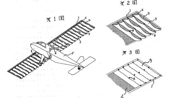
Abstract -- A wing of an ornithopter comprises an inner wing section and an outer wing section. A middle frame of the outer wing section and a pull rod connected with the middle frame are respectively threaded through a connecting part of the front section and the back section of wing ribs of the inner section and the outer wing section; when the outer wing section is pulled by the pull rod and the wing is raised, the wing rib is folded with a connecting point as the axis and when the wing swoops, the wing rib is unfolded. An angle limiter is respectively arranged on the front wing rib and the back wing rib to control the folding angle of the front wing rib and the back wing rib so as to lead the wing of the ornithopter to acquire higher rising and flying force when the wing flutters.
Abstract -- A wing of an ornithopter comprises an inner wing section and an outer wing section. A middle frame of the outer wing section and a pull rod connected with the middle frame are respectively threaded through a connecting part of the front section and the back section of wing ribs of the inner section and the outer wing section; when the outer wing section is pulled by the pull rod and the wing is raised, the wing rib is folded with a connecting point as the axis and when the wing swoops, the wing rib is unfolded. An angle limiter is respectively arranged on the front wing rib and the back wing rib to control the folding angle of the front wing rib and the back wing rib so as to lead the wing of the ornithopter to acquire higher rising and flying force when the wing flutters.
Ornithopter
CN201183610
CN201183610

Inventor(s): GUANGFU HUANG [CN]; CHEN HUANG [CN]
Abstract -- The utility model relates to a flapping-wing aircraft and aims at overcoming the defects that prior flapping-wing aircraft imitates the flying principle of birds, has complicated structure large energy consumption and slow flying speed. For the aircraft, a wing flap is arranged above the fuselage through a fixed frame; a transmission system, a wing-turning device and a retractable device are arranged in the wing flap; a wing with a retractable fan shape is arranged beside the wing flap. Therefore, the wing acquires sufficient lifting force and high speed so that the aircraft can independently accomplish vertical take-off, landing, forward flight, backward flight, turning and horizontal flight without deviation. The aircraft can achieve catapult parachuting; the device has flying flexibility and reliability as well as practicality.
Abstract -- The utility model relates to a flapping-wing aircraft and aims at overcoming the defects that prior flapping-wing aircraft imitates the flying principle of birds, has complicated structure large energy consumption and slow flying speed. For the aircraft, a wing flap is arranged above the fuselage through a fixed frame; a transmission system, a wing-turning device and a retractable device are arranged in the wing flap; a wing with a retractable fan shape is arranged beside the wing flap. Therefore, the wing acquires sufficient lifting force and high speed so that the aircraft can independently accomplish vertical take-off, landing, forward flight, backward flight, turning and horizontal flight without deviation. The aircraft can achieve catapult parachuting; the device has flying flexibility and reliability as well as practicality.
Ornithopter
transmission mechanism capable of being separated into two
segments
CN201143993
CN201143993

Inventor(s): YUNFU XU [CN]
Abstract -- An actuating mechanism for a folding two-section ornithopter is provided. The utility model drives a transmission shaft (2) via an engine or a motor (1); then, the utility model drives a left side transmission gear (4) and a left side transmission crankshaft (5); the top section (10) of the left side transmission crankshaft is connected to a tie bar on a left side wing of the ornithopter. Meanwhile, the left side transmission gear (4) is horizontally connected with a right side transmission gear (6); the left side transmission gear (6) drives a left side transmission crankshaft (7); the top section (11) of the left side transmission crankshaft (7) is connected with a tie bar on a right side wing of the ornithopter. Therefore, the left side transmission gear and the right side transmission gear in the utility model can rotate synchronically towards different direction.
Abstract -- An actuating mechanism for a folding two-section ornithopter is provided. The utility model drives a transmission shaft (2) via an engine or a motor (1); then, the utility model drives a left side transmission gear (4) and a left side transmission crankshaft (5); the top section (10) of the left side transmission crankshaft is connected to a tie bar on a left side wing of the ornithopter. Meanwhile, the left side transmission gear (4) is horizontally connected with a right side transmission gear (6); the left side transmission gear (6) drives a left side transmission crankshaft (7); the top section (11) of the left side transmission crankshaft (7) is connected with a tie bar on a right side wing of the ornithopter. Therefore, the left side transmission gear and the right side transmission gear in the utility model can rotate synchronically towards different direction.
ORNITHOPTER
JP2008254714
JP2008254714
Inventor(s): ISOGAI KOJI; SATO HIROYUKI
Abstract -- PROBLEM TO BE SOLVED: To provide an excellent ornithopter which quickly flies high, by outputting large thrust by realizing ideal flapping motion, by providing flapping amplitude of vibration and feathering amplitude of vibration of large amplitude of a flapping wing in a high flapping frequency, without requiring a complicated and heavy driving control circuit device. ; SOLUTION: In this resonance type ornithopter, the flapping wing is constituted by bonding and fixing one elastic plate material to one elastic bar material as a wing plate, with the one elastic bar material as a wing shaft. By forcibly vibrating and driving the flapping wing in specific amplitude in the flapping motion direction in a natural frequency of the one elastic bar material, the one elastic bar material is resonantly vibrated in the flapping motion direction, and flapping motion is provided by aerodynamically elastically deforming the one elastic plate material.
Abstract -- PROBLEM TO BE SOLVED: To provide an excellent ornithopter which quickly flies high, by outputting large thrust by realizing ideal flapping motion, by providing flapping amplitude of vibration and feathering amplitude of vibration of large amplitude of a flapping wing in a high flapping frequency, without requiring a complicated and heavy driving control circuit device. ; SOLUTION: In this resonance type ornithopter, the flapping wing is constituted by bonding and fixing one elastic plate material to one elastic bar material as a wing plate, with the one elastic bar material as a wing shaft. By forcibly vibrating and driving the flapping wing in specific amplitude in the flapping motion direction in a natural frequency of the one elastic bar material, the one elastic bar material is resonantly vibrated in the flapping motion direction, and flapping motion is provided by aerodynamically elastically deforming the one elastic plate material.
An ornithopter
mechanism
GB2444068
GB2444068

Inventor(s): CHILD ROBIN EDWARD
Abstract -- A Scotch yoke mechanism provides a primary reciprocating motion, and a secondary reciprocating motion which is 90 degrees out of phase with the primary reciprocation motion. A motor rotates an eccentric crank having a drive pin 5, which cooperates with a slot in a yoke 8 to cause reciprocation thereof. Attached to the drive pin 5 are two independently rotating pulleys 21, 22, each pulley carrying lines or belts 20 which arrive and leave in a direction normal to the reciprocation of the yoke 8 when in use. The belts are wrapped half way around each pulley 21, 22, and each belt engages further idler pulleys 19 located on the same plane and mounted on the yoke. The mechanism attempts to mimic the flapping motion in flight of hummingbirds, and insects, eg. bees. The motion of the lines 20 may be transmitted via racks, pinions, bevel gears, or shafts to operate the wings
Abstract -- A Scotch yoke mechanism provides a primary reciprocating motion, and a secondary reciprocating motion which is 90 degrees out of phase with the primary reciprocation motion. A motor rotates an eccentric crank having a drive pin 5, which cooperates with a slot in a yoke 8 to cause reciprocation thereof. Attached to the drive pin 5 are two independently rotating pulleys 21, 22, each pulley carrying lines or belts 20 which arrive and leave in a direction normal to the reciprocation of the yoke 8 when in use. The belts are wrapped half way around each pulley 21, 22, and each belt engages further idler pulleys 19 located on the same plane and mounted on the yoke. The mechanism attempts to mimic the flapping motion in flight of hummingbirds, and insects, eg. bees. The motion of the lines 20 may be transmitted via racks, pinions, bevel gears, or shafts to operate the wings
ORNITHOPTER
JP2008081094
JP2008081094

Inventor(s): ISOGAI KOJI; UESAWA YUICHI
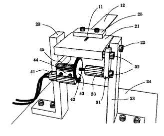
Abstract -- PROBLEM TO BE SOLVED: To provide an excellent ornithopter having an excellent power transmission efficiency and capable of performing an alert and highly maneuvarable flight by performing a flapping motion with a high flapping frequency since a large output can be provided by rotatingly driving a rotary motor at high speeds without requiring a complicated and heavy drive control circuit device and the large output from the rotary motor is converted into a flapping motion without a large mechanical loss. ; SOLUTION: In this resonance ornithopter, a flapping blade forms a blade vibration system performing a compound resonance in two degree-of-freedom; flapping vibration and feathering vibration. A vibrating motor generating an inertia force in the circumferential direction by the flapping blade pivotally supported on a flapping vibration pivot shaft is supportedly installed. A flapping vibration torque and a feathering vibration torque can be provided by the inertia force generated by the vibrating motor.
Abstract -- PROBLEM TO BE SOLVED: To provide an excellent ornithopter having an excellent power transmission efficiency and capable of performing an alert and highly maneuvarable flight by performing a flapping motion with a high flapping frequency since a large output can be provided by rotatingly driving a rotary motor at high speeds without requiring a complicated and heavy drive control circuit device and the large output from the rotary motor is converted into a flapping motion without a large mechanical loss. ; SOLUTION: In this resonance ornithopter, a flapping blade forms a blade vibration system performing a compound resonance in two degree-of-freedom; flapping vibration and feathering vibration. A vibrating motor generating an inertia force in the circumferential direction by the flapping blade pivotally supported on a flapping vibration pivot shaft is supportedly installed. A flapping vibration torque and a feathering vibration torque can be provided by the inertia force generated by the vibrating motor.
ORNITHOPTER
JP2008024049
JP2008024049

Inventor(s): NAKAZATO KATSUYOSHI
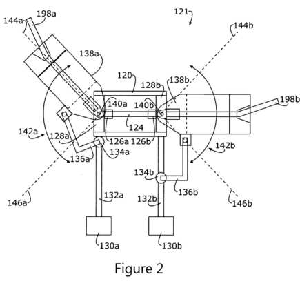
Abstract -- PROBLEM TO BE SOLVED: To a comparatively large-sized orinthopter having extremely original/innovative mechanism, and capable of flying while embarking a human in the future. ; SOLUTION: The opnithopter comprises a machine body 10, wings 20 mounted to the machine body 10, and a flapping mechanism materializing flapping motion of the wings 20. The flapping mechanism has slanting shaft members 40F/40R fixed to the machine body 10, moving members 41F/41R constructed so as to reciprocate along the slanting shaft members 40F/40R and coupled to wing base portions of the wings 20 through hinge portions, a driving portion 42 driving the moving members 41F/41R to reciprocate, and wing supporting members 43F, 43R coupling the machine body 10 and the wings 20 and supporting position separated from the wing base portions of the wings 20 by a predetermined distance. Lead-lag motion is materialized simultaneously with the flapping motion of the wings
Abstract -- PROBLEM TO BE SOLVED: To a comparatively large-sized orinthopter having extremely original/innovative mechanism, and capable of flying while embarking a human in the future. ; SOLUTION: The opnithopter comprises a machine body 10, wings 20 mounted to the machine body 10, and a flapping mechanism materializing flapping motion of the wings 20. The flapping mechanism has slanting shaft members 40F/40R fixed to the machine body 10, moving members 41F/41R constructed so as to reciprocate along the slanting shaft members 40F/40R and coupled to wing base portions of the wings 20 through hinge portions, a driving portion 42 driving the moving members 41F/41R to reciprocate, and wing supporting members 43F, 43R coupling the machine body 10 and the wings 20 and supporting position separated from the wing base portions of the wings 20 by a predetermined distance. Lead-lag motion is materialized simultaneously with the flapping motion of the wings
A winged device
to mimic wing movement of insects / hummingbirds
GB2433059

GB2433059
Inventor(s): SINCLAIR PETER LOGAN [GB]
Also published as: US2008272231 // WO2007066092
Abstract -- A winged device comprises an axial support mounted for reciprocating rotary motion about a longitudinal axis of the support, a first wing vane 1 mounted to the axial support 3 for rotation therewith, and a second wing vane 2 hingedly mounted to the axial support 3. The first wing vane 1 is connected by a connector 4, 24 to a cam follower 24 which is constrained to a defined movement path by a cam 23, while the second wing vane 2 is also connected to the cam follower via another connector 5, 25. Through this connection, reciprocation motion of the axial support causes the relative orientation of the wing vanes to change, hence causing flexure / bending of the wing 1, 2. A guide rail and follower may be used in place of the cam and follower mechanism. This ornithopter attempts to mimic the motion of wings of a hummingbird / insect in flight.
Foldaway
two-section-type wings for ornithopter
CN2918218


CN2918218
Inventor(s): XU YUNFU [CN]
Abstract -- The utility model relates to a two-segment ornithopter wing, comprising an inner wing segment and an outer wing segment which can be folded symmetrically. A transmission crankshaft is connected with a pull rod, the pull rod traverses the top of the inner wing segment skeleton in the fuselage, and outward is connected with the vertex of an extend segment, which is a segment of the outer wing segment over the junction of the inner and outer wing segment, in the way, the pull rod is driven by the circular motion of the transmission crankshaft, the outer wing segment skeleton is pulled by the pull rod and in the lever motion with the fulcrum which is a junction of the inner and outer wing segment, the inner wing segment skeleton is also in the lever motion synchronously with the fulcrum which is the junction of the inner wing segment and the fuselage, making the flutter of wing look like the motion state of the bird wing very much.
Abstract -- The utility model relates to a two-segment ornithopter wing, comprising an inner wing segment and an outer wing segment which can be folded symmetrically. A transmission crankshaft is connected with a pull rod, the pull rod traverses the top of the inner wing segment skeleton in the fuselage, and outward is connected with the vertex of an extend segment, which is a segment of the outer wing segment over the junction of the inner and outer wing segment, in the way, the pull rod is driven by the circular motion of the transmission crankshaft, the outer wing segment skeleton is pulled by the pull rod and in the lever motion with the fulcrum which is a junction of the inner and outer wing segment, the inner wing segment skeleton is also in the lever motion synchronously with the fulcrum which is the junction of the inner wing segment and the fuselage, making the flutter of wing look like the motion state of the bird wing very much.
Manual
wing-flapping craft
CN200954879

CN200954879
Inventor(s): YANG BOHAI YANG [CN]
Abstract -- The utility model relates to a manpower ornithopter, an aircraft for sports and entertainment. The utility model consists of a central backbone [1], a triangle arm [4] connected with the both sides of the backbone to produce the up and down movement, a movable handle [2] moving from the front to the rear, a fan wing [3] composed of finger ribs [8] and a horizontal connecting rod and foot pedal [14] to control the fan wing moving up and down, an opened connecting rod [13] and an extendable connecting rod [16] positioned between the connecting rod. The connecting rod is provided with a movable handle [18] of a steel wire [15] to control the movement of the fan wing and the angle, a sleeve button and the vertical tube column [10] and a resistant block [19] at the bottom of the backbone. The vertical tube column is provided with a two-shoulder fixing bracket [19], while the terminal is provided with a seat plate [12] with seat plate rail [21] and a safety rope [20]. The utility model is simple in structure and convenient to manufacture, and can be disassembled to carry around, thereby partially resolving the problems of transportation and travel.
Abstract -- The utility model relates to a manpower ornithopter, an aircraft for sports and entertainment. The utility model consists of a central backbone [1], a triangle arm [4] connected with the both sides of the backbone to produce the up and down movement, a movable handle [2] moving from the front to the rear, a fan wing [3] composed of finger ribs [8] and a horizontal connecting rod and foot pedal [14] to control the fan wing moving up and down, an opened connecting rod [13] and an extendable connecting rod [16] positioned between the connecting rod. The connecting rod is provided with a movable handle [18] of a steel wire [15] to control the movement of the fan wing and the angle, a sleeve button and the vertical tube column [10] and a resistant block [19] at the bottom of the backbone. The vertical tube column is provided with a two-shoulder fixing bracket [19], while the terminal is provided with a seat plate [12] with seat plate rail [21] and a safety rope [20]. The utility model is simple in structure and convenient to manufacture, and can be disassembled to carry around, thereby partially resolving the problems of transportation and travel.
Ornithopter
CN2808739
CN2808739

Inventor(s): MO QIQI [CN]
Abstract -- The utility model provides a flapping wing aircraft which supplies lift force stably and realizes manned flight. The utility model has the structure that the utility model comprises an aircraft body, an engine, a drive component and flapping wings, wherein the flapping wings are symmetrically arranged at both sides of the aircraft body and the engine is linked with the flapping wings through the drive component. The utility model is characterized in that each flapping wing comprises a skeleton, an elastic wing body and a flapping arm; the elastic wing body forms a half-cone shape and covers the skeleton, the flapping arm which runs through the framework transversely is provided with a plurality of joints and one end of the flapping arm is connected to the drive component. Flapping wing aircrafts manufactured by the principle of the utility model can realize manned flight, and the horizontally degree of the aircraft is increased.
Abstract -- The utility model provides a flapping wing aircraft which supplies lift force stably and realizes manned flight. The utility model has the structure that the utility model comprises an aircraft body, an engine, a drive component and flapping wings, wherein the flapping wings are symmetrically arranged at both sides of the aircraft body and the engine is linked with the flapping wings through the drive component. The utility model is characterized in that each flapping wing comprises a skeleton, an elastic wing body and a flapping arm; the elastic wing body forms a half-cone shape and covers the skeleton, the flapping arm which runs through the framework transversely is provided with a plurality of joints and one end of the flapping arm is connected to the drive component. Flapping wing aircrafts manufactured by the principle of the utility model can realize manned flight, and the horizontally degree of the aircraft is increased.
Ornithopter
wing mechanism
CZ16862
CZ16862

Inventor(s): ZAJICEK KAMIL [CZ]
Flapping wing
aircraft
CN101041383
CN101041383
Inventor(s): ZHANG JIN ZHANG [CN]
Abstract -- The invention relates to an aircraft imitating bird flying method. There is a U-shape groove on flapping wing surface to constitute a spring plate. A thin plate is connected under the spring plate of flapping wing. A control box is set on the body and a motor is connected in the control box. The motor is connected with crank and the crank is connected with slide bar. On the slide bar there is a slide block, which is connected with two connecting rods to draw flapping wings move. At the tail of body there are horizontal tail actuator, vertical tail actuator and control actuator. The control actuator is connected with the control box by rotary table and shift lever. The control box is connected with the rotary shaft. The horizontal tail actuator is connected with the horizontal tail by rotary table and shift lever and the vertical tail actuator is connected with the vertical tail by rotary table and shift lever. Merits of invention are that 1 the up-down flapping resistance of flapping wing is small; 2 under the actuator control, the aircraft of flapping wing flies flexibly and skillfully, the operation is easy and the oil consumption is small; 3 the structure is simple and the preparation is convenient.
Abstract -- The invention relates to an aircraft imitating bird flying method. There is a U-shape groove on flapping wing surface to constitute a spring plate. A thin plate is connected under the spring plate of flapping wing. A control box is set on the body and a motor is connected in the control box. The motor is connected with crank and the crank is connected with slide bar. On the slide bar there is a slide block, which is connected with two connecting rods to draw flapping wings move. At the tail of body there are horizontal tail actuator, vertical tail actuator and control actuator. The control actuator is connected with the control box by rotary table and shift lever. The control box is connected with the rotary shaft. The horizontal tail actuator is connected with the horizontal tail by rotary table and shift lever and the vertical tail actuator is connected with the vertical tail by rotary table and shift lever. Merits of invention are that 1 the up-down flapping resistance of flapping wing is small; 2 under the actuator control, the aircraft of flapping wing flies flexibly and skillfully, the operation is easy and the oil consumption is small; 3 the structure is simple and the preparation is convenient.
MUSCLE-POWERED
ORNITHOPTER
WO2009074349
WO2009074349
Inventor(s): PIETREK NIKOLAUS
Abstract -- The invention relates to a muscle-powered ornithopter comprising a fuselage, a pair of flapping wings which have a modifiable profile or an aileron in an external wing section located at a distance from the fuselage, said modifiable profile or aileron allowing the lift to be modified in a predefined current, and an elevator unit in which the deflection of the elevator can be modified. The pair of flapping wings and the fuselage are made of an elastic material, the elasticity of which allows the pair of flapping wings to be flapped. The flapping wings are curved downward in a resting position. The elasticity is calculated such that the flapping wings are urged into a neutral position during a flight because of the pilot's weight.; The fuselage is designed to accommodate the pilot in a vertical position relative to a longitudinal axis of the fuselage such that the pilot can apply stress to and relieve stress from the aircraft in phases by stretching and bending his or her legs. The ornithopter further comprises mechanisms which allow the modifiable external wing sections and the modifiable deflection of the elevator to be actuated in phase with the movement of the flapping wings.
Abstract -- The invention relates to a muscle-powered ornithopter comprising a fuselage, a pair of flapping wings which have a modifiable profile or an aileron in an external wing section located at a distance from the fuselage, said modifiable profile or aileron allowing the lift to be modified in a predefined current, and an elevator unit in which the deflection of the elevator can be modified. The pair of flapping wings and the fuselage are made of an elastic material, the elasticity of which allows the pair of flapping wings to be flapped. The flapping wings are curved downward in a resting position. The elasticity is calculated such that the flapping wings are urged into a neutral position during a flight because of the pilot's weight.; The fuselage is designed to accommodate the pilot in a vertical position relative to a longitudinal axis of the fuselage such that the pilot can apply stress to and relieve stress from the aircraft in phases by stretching and bending his or her legs. The ornithopter further comprises mechanisms which allow the modifiable external wing sections and the modifiable deflection of the elevator to be actuated in phase with the movement of the flapping wings.
Ornithopter
with independently controlled wings
US2005269447
US2005269447
Inventor(s): CHRONISTER NATHAN J [US]
Abstract -- The invention described here offers a more effective method of ornithopter flight control. To accomplish this, the ornithopter has dual microprocessor-controlled drive systems for flapping the wings independently of each other. Various wing movements can cause the ornithopter to turn, roll, or pitch up or down. Weight and complexity are reduced by eliminating the need for servo-controlled tail surfaces.
Abstract -- The invention described here offers a more effective method of ornithopter flight control. To accomplish this, the ornithopter has dual microprocessor-controlled drive systems for flapping the wings independently of each other. Various wing movements can cause the ornithopter to turn, roll, or pitch up or down. Weight and complexity are reduced by eliminating the need for servo-controlled tail surfaces.
DRIVING
MECHANISM OF ORNITHOPTER HAVING IMPROVED FLYING EFFICIENCY
TO ENABLE STABLE FLIGHT BY REDUCING LOAD APPLIED TO
CONNECTING RODS AND FACILITATING FLAPPING MOTION
KR20050011646
KR20050011646
Inventor(s): CHANG JO WON
Abstract -- PURPOSE: A driving mechanism of an ornithopter is provided to enable a constant, stable flight of the ornithopter by adjusting a gear deceleration ratio, reducing a load applied to connecting rods and facilitating a flapping motion of a wing segment, to reduce sizes of the wing segment and to extend a set time of the ornithopter, thereby improving flying efficiency and performance. CONSTITUTION: The driving mechanism of an ornithopter comprises: a motor(21); a first decelerating gear(23) and second decelerating gears(24) connected to a motor shaft gear, the second decelerating gears(24) having connecting rods(26) symmetrically disposed to be connected to both wing segments and inducing smooth vertical motion; and a shaft center(29) and a trailing edge joint(29A) about which the wing segments perform flapping motions.
Abstract -- PURPOSE: A driving mechanism of an ornithopter is provided to enable a constant, stable flight of the ornithopter by adjusting a gear deceleration ratio, reducing a load applied to connecting rods and facilitating a flapping motion of a wing segment, to reduce sizes of the wing segment and to extend a set time of the ornithopter, thereby improving flying efficiency and performance. CONSTITUTION: The driving mechanism of an ornithopter comprises: a motor(21); a first decelerating gear(23) and second decelerating gears(24) connected to a motor shaft gear, the second decelerating gears(24) having connecting rods(26) symmetrically disposed to be connected to both wing segments and inducing smooth vertical motion; and a shaft center(29) and a trailing edge joint(29A) about which the wing segments perform flapping motions.
REMOTELY
CONTROLLED ORNITHOPTER CAPABLE OF INDUCING APPROPRIATE
FLAPPING MOTION AND HAVING REDUCED WING SIZE BY IMPROVING
FLYING EFFICIENCY AND INCREASING FLIGHT MANEUVERABILITY
KR20050011645
ORNITHOPTER HAVING EXCELLENT MECHANICAL STRENGTH AND GLOSS AND HIGH LEVEL OF AIR SHIELDING CAPABILITY USING ALUMINUM DEPOSITED PET FILM
KR20050011644
ATTITUDE CONTROL APPARATUS AND RADIO-CONTROLLED ORNITHOPTER COMPRISING THE SAME
KR20050034364
Vertical landing assistant airplane
CN1590218
Ever-distance dynamic frame tye two-layer ornithopter aircraft
CN1579882
Couple distance moving arc type feathering aricraft
CN1513726
ORNITHOPTER SYSTEM FOR A VERTICAL TAKE-OFF AND LANDING AIRPLANE WITH A PAIR OF WINGS HAVING A WING FRONT SHAFT AND A WING REAR PART INSTALLED AT A ROTARY CONE AND A ROTARY CYLINDER, RESPECTIVELY
KR20050003677
ORNITHOPTER WITH FLEXIBLE FUSELAGE
WO03105559
POWER ASSEMBLY FOR ORNICOPTER
WO03104079
Ornithopter wing with holes and loosen leaves
CN2617681
Airfoil having holes and flaps for ornithopter
CN1541893
Biomimetic mechanism for micro aircraft
US2004056149
RECIPROCATING FLUID ENGINE
WO03058072
FLYING VEHICLE, TYPE ORNITHOPTER
RU2236988
Control system for ornithopter
US6659397
Ornithopter
CN2581325
Flapping wings type airplane of imitating birds
CN1480375
Power-driven ornithopter piloted by remote controller
US6550716
Power-driven ornithopter
US2003096553
ORNITHOPTER
RU2270136
ORNITHOPTER WING
BG105894
Multi-wing ornithopter
CN2488815
Ornithopter
US2002173217
Winding device and ornithopter utilizing same
US2002065015
Ornithopter
CN2450088
Ornithopter
CN2452886
Ornithopter
CN1338415
Bionic ornithopter
CN2433175
Light ornithopter
CN2431210
WING CONSTRUCTION FOR ORNITHOPTER
WO0053492
ORNITHOPTER
WO9965767
Manpower ornithopter
CN2378287
Interlinking driving launch ornithopter
CN2324063
METHOD OF VERTICAL TAKEOFF AND LANDING OF AN ORNITHOPTER
WO9822339
Ornithopter
US5899408
Flapping-wing aircraft
CN1143590
Ornithopter driven by pilot's muscle force
DE19509774
Mixed ornithopter
CN2213118
Ornithopter driven by manpower
CN2197310
HEAVIER-THAN-AIR FLYING VEHICLE, TYPE ORNITHOPTER
RU2096266
Ornithopter wing
CN1097393
TOY ORNITHOPTER
KR0117142
ORNITHOPTER
LT1642
ORNITHOPTER WING
RU2089460
Manpower ornithopter
CN1079192
Steering and propulsion device and method for an aircraft with flexible articulated wings
FR2687125
ORNITHOPTER
RU2007338
ORNITHOPTER
BG50601
Ornithopter-type device, with flapping wings, using human muscle power for propulsion
FR2680351
ORNITHOPTER
CN2122118
ORNITHOPTER
CN1067625
ORNITHOPTER
RU2007337
ARM-TYPE MAN-DRIVEN ORNITHOPTER
CN2098466
MECHANISM OF DRIVING OF ORNITHOPTER
SU1818275
Ornithopter
GB2209727
ORNITHOPTER
CN2038086
DRIVING DEVICE FOR BLADES OF ORNITHOPTER MODEL
SU1728086
Means for and methods of controlling ornithopters
US4712749
Ornithopter
FR2582616
Structure intended for carrying out flapping flight by the upper plane of a biplane ornithopter by use of muscle power
FR2572053
Rotary-wing aircraft having an ornithopter drive
DE3343187
MAN POWERED ORNITHOPTER
AU3357284
ORNITHOPTER WITH SINGLE HYDRAULIC CYLINDER PULLING BOTH WINGS
AU1448683
AERODYNAMICALLY-INDUCED WING-FLAPPING FOR THE PROPULSION OF ORNITHOPTERS
CA1183509
ORNITHOPTER BLADES DRIVE
SU1052248
ORNITHOPTER WING DRIVING MECHANISM
SU878652
ORNITHOPTER WING DRIVE
SU1121182
Ornithopter construction
US4195438
Articulated wing ornithopter
US4139171
ORNITHOPTER
GB1523902
AIRFOIL WING FOR AIRCRAFT
GB1393696
TOY ORNITHOPTER WIND-DRIVING MECHANISM
US3728814
VARIABLE GEOMETRY ORNITHOPTER
GB1338696
ORNITHOPTER WING
GB1283583
FLYING TOYS
GB1318342
TOY ORNITHOPTER WING-DRIVING MECHANISM
GB1263079
ORNITHOPTER
SU304185
Ornithopter type aircraft
US3161376
Improvements in or relating to ornithopters
GB922233
Improvements relating to ornithopters
GB885273
Ornithopter
US2985407
Improvements relating to ornithopters
GB851352
Improvements in ornithopters
GB711410
Toy ornithopter
US2504567
Improvements in or relating to ornithopters
GB617019
Improved ornithopter
GB525256
Improvements in or relating to ornithopters
GB458104
Ornithopter
GB442667
Improvements in or relating to ornithopters
GB415566
Ornithopter wing structure
US1913011
Ornithopter
GB404356
Machines supported by rotary propellers, with combined propelling, flapping and steering action
GB383973
An improved flying machine
GB377744
Ornithopter
US1884909
Improvements in or relating to flying machines
GB348946
Improvements in aircraft of the ornithopter type
GB342339
Improvements in and relating to aircraft
GB322183
Ornithopter
US1726915
Flying apparatus
GB289829
Ornithopter
US1783029
Improved mechanism for converting rotary into reciprocatory motion
GB163283
An improved aerial machine
GB157977
Improvements in or relating to means for converting rotary into reciprocatory motion
GB157870
Improvements in or relating to ornithopter flying machines
GB146648
Flying Machine.
GB116914
An Improved Aerial Machine of the Ornithopter Type.
GB191514862
An Improved Flying Machine.
GB191509931
Improvements in and relating to Flying Machines.
GB191419774
Improvements in and relating to Flying Machines.
GB191223033
ORNITHOPTER
CA527716
Wing
surface jet vortex flapping wing aircraft
CN2928681
Wing-like aircraft
CN2889901
Prey-bird machine tail
CN1895961
US7255305
Flying device utilizing natural principles
Wing type aerial craft having upper and lower branched fanlike wings
CN1600641
WING MECHANISM REALIZING VARIOUS MOTION OF WINGS AND AIR VEHICLE THEREOF BY CONNECTING THE MOVEMENTS OF TWO RECIPROCATION APPARATUSES THROUGH COUPLINGS
KR20050006375
L-tail ( featuring parabrake )
US2004089765
Multi-wing ornithopter
CN2488815
Bionic ornithopter
CN2433175
JP2965201
FLYING BODY
Pedal-type aircraft
CN2172748
Adaptation of bird wing structures to glider wing - involves top line curvature on wing suction side with the same curvature over entire span
DE4133491
Wing surface jet vortex flapping wing aircraft
CN2928681
DE4125974
Oscillating vane or wing drive with main motor for vertical motion - has servomotors for independent vane rotation synchronised to vertical motion
DE4039635
Power transmission device for movable wing flying machine - comprises housing contg. movable slide ring to which striker arm is fitted
Flutter mechanism for toy ornithopter
CN2551303
REMOTE CONTROL ORNITHOPTER
KR100919066
Micro-miniature ornithopter
CN201305134
Mini ornithopter
CN101412441
Flapping wing capable of being bent in one direction of miniature ornithopter
CN101492094
REMOTE-CONTROLLED FLUTTERING OBJECT CAPABLE OF FLYING FORWARD IN UPRIGHT POSITION
WO2009088113
Ornithopter electromagnetic steering device
CN201049212
Wing surface jet vortex flapping wing aircraft
CN2928681
Two segmented type wings of minitype ornithopter
CN101049859
Driving mechanism for wings of minitype ornithopter
CN101049858
Rolling control mechanism for minitype ornithopter
CN101041382
TOY ORNITHOPTER
KR200381806
Method of control for toy aircraft
US2006032975
DRAGONFLY-TYPE ORNITHOPTER WITH TWO PAIRS OF WING
KR20060110241
Wing of ornithopter
CN101417708
Ornithopter having a wing structure and a mechanism for imparting realistic, bird-like motion thereto
US7607610
Ornithopter
US2007295858
Man-powered ornithopter-sailplane
US2007029441
ORNITHOPTER
JP3879771
Flapping wing for ornithopter
CN1608945
Flying device utilizing natural principles
US2006102782
Ornithopter
CN2778678
ACTUATION SYSTEM OF ORNITHOPTER
KR20060030317
Aircraft with flapping wings
CN1629038
ORNITHOPTER KIT
KR20050090540
TOY ORNITHOPTER AIRCRAFT
US2003054724
Universal power device for bionic ornithopter models
CN2688344
CN2928681
Wing-like aircraft
CN2889901
Prey-bird machine tail
CN1895961
US7255305
Flying device utilizing natural principles
Wing type aerial craft having upper and lower branched fanlike wings
CN1600641
WING MECHANISM REALIZING VARIOUS MOTION OF WINGS AND AIR VEHICLE THEREOF BY CONNECTING THE MOVEMENTS OF TWO RECIPROCATION APPARATUSES THROUGH COUPLINGS
KR20050006375
L-tail ( featuring parabrake )
US2004089765
Multi-wing ornithopter
CN2488815
Bionic ornithopter
CN2433175
JP2965201
FLYING BODY
Pedal-type aircraft
CN2172748
Adaptation of bird wing structures to glider wing - involves top line curvature on wing suction side with the same curvature over entire span
DE4133491
Wing surface jet vortex flapping wing aircraft
CN2928681
DE4125974
Oscillating vane or wing drive with main motor for vertical motion - has servomotors for independent vane rotation synchronised to vertical motion
DE4039635
Power transmission device for movable wing flying machine - comprises housing contg. movable slide ring to which striker arm is fitted
Flutter mechanism for toy ornithopter
CN2551303
REMOTE CONTROL ORNITHOPTER
KR100919066
Micro-miniature ornithopter
CN201305134
Mini ornithopter
CN101412441
Flapping wing capable of being bent in one direction of miniature ornithopter
CN101492094
REMOTE-CONTROLLED FLUTTERING OBJECT CAPABLE OF FLYING FORWARD IN UPRIGHT POSITION
WO2009088113
Ornithopter electromagnetic steering device
CN201049212
Wing surface jet vortex flapping wing aircraft
CN2928681
Two segmented type wings of minitype ornithopter
CN101049859
Driving mechanism for wings of minitype ornithopter
CN101049858
Rolling control mechanism for minitype ornithopter
CN101041382
TOY ORNITHOPTER
KR200381806
Method of control for toy aircraft
US2006032975
DRAGONFLY-TYPE ORNITHOPTER WITH TWO PAIRS OF WING
KR20060110241
Wing of ornithopter
CN101417708
Ornithopter having a wing structure and a mechanism for imparting realistic, bird-like motion thereto
US7607610
Ornithopter
US2007295858
Man-powered ornithopter-sailplane
US2007029441
ORNITHOPTER
JP3879771
Flapping wing for ornithopter
CN1608945
Flying device utilizing natural principles
US2006102782
Ornithopter
CN2778678
ACTUATION SYSTEM OF ORNITHOPTER
KR20060030317
Aircraft with flapping wings
CN1629038
ORNITHOPTER KIT
KR20050090540
TOY ORNITHOPTER AIRCRAFT
US2003054724
Universal power device for bionic ornithopter models
CN2688344
ORNITHOPTER AND FLAPPING FLIGHT METHOD
JP2005119658
ORNITHOPTER
JP2007237