Jacques Ravatin was an associate of Leon Sprink. Ravatin invented smaller and more powerful versions of the Sprink Space Activator :
Description
The present invention refers to an equipment making it possible to amplify the emissions due to the forms, in particular with the single geometric forms presenting a minimum of symmetry.
It is known that certain geometric forms, for example pyramids, are, when they present appropriate proportions, the seat of emissions which one could not determine to present the exact nature. One noted that such emissions had effects, in particular on the living organisms.
Until present, it was not possible to obtain with the aforementioned emissions due to the forms, of the measurable and exploitable effects in industry.
The present invention has as an object an apparatus making it possible to amplify, according to a said principle of “localization”, the emissions due to forms to obtain industrially exploitable effects.
According to the present invention, such an apparatus comprises essentially a geometric form presenting a minimum of symmetry in planar or space, this form being associated a device producing an electric and/or magnetic and/or electromagnetic field in determined volume by the aforementioned form or in the vicinity immediate of this volume, such fields being able to be fixed or movable compared to the aforementioned form, and being able to be modulated or not.
According to an embodiment prefered of the invention, the aforementioned form is a substantially regular polygonal frame with 16 dimensions and is associated a device producing an electric power in the volume delimited by the aforementioned frame, this device comprising four electrodes with dimensions regularly spaced on the aforesaid frame in their medium, two of the aforesaid electrodes having a stable, filtered continuous positive potential compared to the ground to which other electrodes are connected, the formed angle by the points of the two positive electrodes being, preferably, of approximately 28 degrees apart, while that formed by the points of the two negative electrodes is, preferably, of approximately 23 degrees.
The aforementioned positive potential is preferably of at least 45 kilovolts and preferably of at least 60 Kv, the aforementioned electrodes having the general shape of points directed towards the center of the aforesaid frame, the points of the four said electrodes being, preferably, in a same plane, which is preferably, the planar mediator of the aforesaid polygonal frame, the square dummy one delimited by the of the aforesaid points four electrodes being concentric by report/ratio to that the frame and having diagonal approximately 400 millimeters at least for a potential of approximately 45 Kv and approximately at least 1 metre for a potential of approximately 300 Kv, the diameter of the circle circumscribed with the formed polygon by the aforementioned frame being at least 200 centimetres for a potential of approximately 45 Kv, and at least 280 cm for a potential of approximately 300 Kv.
According to an advantageous characteristic of the invention, the frame is made in a material, preferably out of a natural material, of which the structure, with the level of fibres or the crystalline level, is directed or has itself of remarkable symmetries. Preferably, each side of the polygonal frame is constructed of a small, very dry solid wood plank, the length of the small plank being taken preferably in the direction of fibres of the wood, the different successive small planks being connected between them by glue or using pegs, also made of wood, such pegs not having, preferably, to exceed small pieces.
Natural materials not having any coherent or directed structure, such as for example the rubber, are to be avoided.
According to an embodiment prefered of the invention, some of the small planks forming the with dimensions ones of the polygonal frame are with character of a right Moebius strip, and other with character of a left Moebius strip.
According to another embodiment of the invention, equipment comprises two or several regular polygonal concentric frames, each one having different numbers of dimensions.
To reinforce the effect of amplification, one can preferably have on the stems supporting the electrodes the parts, preferably out of same material that that of the frame, having for example round ovoidal or rhomboidal, and when several of these forms are laid out on the same stem of an electrode, dimensions of these parts are homothetic, those having lowest dimensions being close to the corresponding electrode, the other parts being laid out after, and all the more far away from the first their dimensions are larger.
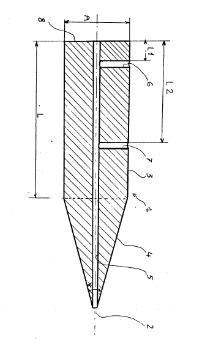
To reinforce the effect of amplification, one can also lay out on certain sides of the form or in proximity volumes preferably manufactured of same material that the frame, these volumes being in general single geometric volumes, for example of the trunks of cylinders finishing with the one their ends by a conical point, the angle of opening of these cones being preferably of approximately 140 degrees.
One can also lay out in the form itself or near inorganic natural or synthetic, such as carborundum.
One can also add systems with acoustic resonance in appropriate places, in proximity to the frame.
The various additional forms can be made out of separate materials, or a single material so their edges can be joined.
The form can also manufactured using a control of appropriate form in which one makes fluid circulation fluid possible.
To further increase the effect of amplification of the device of the invention, one can fix it on a single or equatorial mounting and direct it in an appropriate way.
The present invention will be better understood using the detailed description of several taken embodiments like the nonrestrictive examples illustrated by the annexed drawings, in which
- Figure 1 is a planar view of an embodiment prefered of an according device to the present invention;

- Figures 2 and 3 are cross-sections of two embodiments of electrodes of the devices of figures 1 and 2; and,


- Figure 4 is a schematic view of an alternative of the device of Figure 1.

The apparatus of amplification represented on Figure 1 includes essentially a geometric form F and four electrodes with their stem electrode holders affixed to create an electric field in the volume delimited by the aforementioned form, and in the vicinity.
In the case of the embodiment prefered of the invention represented on Figure 1, the present form F like an hollow cylinder lof shallow depth, the wall of this cylinder, or frame, having out of radial cut substantially the shape of a regular polygon with 16 sides with dimensions respectively referred 1 to 16.
However, it is clearly understood that the polygonal hollow cylindrical form is not the only one possible, other forms, for example pyramidal forms also can be used in the frame of the invention.
The sixteen sides of the frame materializing the form F can all be substantially identical, and consist each one of a rectangular parallelepiped. However, the applicant noted that if some of the dimensions are different, and in particular if certain sides have a character of left strip of Moebius and other character of straight Moebius strip, one obtains good amplification of the emissions due to the form F.
In the embodiment prefered of the invention represented in Figure I, with dimensions referred the 1, 3, 7, 8, 12,14 and consisted rectangular parallelepipeds, sides 2, 4, 5, 9; 11,13 and 15 consist of volumes with the character of a right Moebius strip and with dimensions the 6 and 10 are left Moebius strips. However, it is clearly understood that other different provisions on the formed sides by rectangular parallelepipeds, by volumes with characters of strip of left and right Moebius can be considered while getting an improvement of amplification also of the aforesaid emissions. By volumes with character strip of Moebius one hears volumes resulting of the twist of 180 degrees of the one of the ends of a rectangular cuboid strip compared to the other end (the strip being supposed to lend itself to such a torsion), this torsion being done around the longitudinal axis of the aforesaid the cuboid strip. The strip of Moebius is said right or left according to whether it can be comparable with a right or left threading respectively.
In the case of the embodiment of figure 1, volumes with the Moebius strips are thicker in their middle ( i.e., they would be carried out starting from a rectangular strip of which the thickness would be larger with the middle than at the ends) in order to allow the drilling of holes in their mediums for the insulators and fixing mounting, as explained below). In practice, it is preferable not to twist a wood small plank, but to cut the aforementioned volumes as Moebius strips. Keys volumes are, preferably, regular, i.e. symmetrical compared to their respective centers, and their total number must be odd.
All with dimensions the 1 to 16 of the form F is made out of very dry wood, for example of poplar, of oak, or an exotic wood.
The applicant noted that the natural materials with fibres directed such as the wood gave the good results, and that materials such as rubber or the plywood, or synthetic products such as plastic did not produce any substantial result.
When with dimensions the 1 to 16 is manufactured out of wood, they are assembled mutually, preferably by assembly of the mortise tenon out of wood which can reinforce the assembly, and not exceeding the dimensions of the frame.
The applicant noted that industrially to obtain useful results, the form F was to be such as the circle circumscribed with the formed polygon by the frame was to have a diameter of at least approximately 250 cm, the high applied tension, in a way explained below, with the electrodes being at least 45 Kv, preferably from at least 60 kv, low tensions to 45 Kv having not very industrially exploitable effects.
Sides 5 and 13 of the frame, with right Moebius strips are drilled of a hole passing by their center and whose axis merges with a radius of the circle circumscribed with the form F. The drilled holes in with dimensions the 5 and 13 are used for fixing of the form F on a mounting, not represented, for example an equatorial or ordinary mounting, making it possible to direct in space the form F. However, one could envisage other modes of fixing of the form F on its mounting.
With dimensions the 3, 7, 11 and 15 are drilled holes, in the same way that sides 5 and 13, in order to allow the fixing of the electrodes, as described below.
Small wood planks constituting the dimensions 1,3,7,8,12,14 16, preferably, have a width equal to or greater than 20 cm and a thickness equal to or greater than 4 cm, preferably between 6 and 10 cm. The sides with right and left Moebius strips have, with their extremities 5 preferably, the same thickness as the planar sides, their thickness gradually increasing ends towards the center, up to a value of approximately at least 8 cm, this, in order to allow the drilling from with dimensions the 5 and 13 for the fixing of the frame on mounting and the sides 11 and 15 for the fixing of the electrodes.
The applicant noted that one could also favorably influence the effect of amplification by affixing with ankles, volumes manufactured in the same material as frame. In the example of realization represented on figure 1, one fixed on the faces, turned towards the inner one of the form, the sides 1 and 9, volumes 17 and 18 respectively manufactured out of wood.
These volumes 17 and 18 consist of cylinders with cones on their ends, the point angle of these cones being preferably approximately 140 degrees, the diameter of the cylinders being low to the length of with dimensions form, and the height of these cylinders being of about size of a few centimetres.
On sides 3, 7, 11 and 15 of the frame constituting the fixed form F one the electrodes 19, 20, 21 and 22 respectively, these electrodes being supported by stems electrode holders 23. Electrodes 19 to 22 are made out of electric conductive good material, for example copper and are consisted a circular cone 24 whose base is connected to the stem electrode holders 23 by one surface of hemisphere 25.
The point angles of electrodes 20 and 21 are, preferably, of 23 degrees +/- 30 ' so that the point angles of the cones of the electrodes 19 and 22 are preferably 28 degrees +/- 30 '. The length of each electrode 19 to 22, taken in the direction of their axis, is approximately 60 to 90 mm. However, other shapes of electrodes can to be considered.
The stems 23, which are, also, made out of an electric conductive good material, for example of copper, and at the ends of which electrodes 19 to 22 are screwed or welded, cross with dimensions the 3, 7, 11 and 15 of the frame constituting the form F through appropriate insulators 26, for example out of glass or porcelain, these insulators drilled with an axial hole having substantially the same diameter that that of the stems electrode holders 23, the stems electrode holders 23 being attached of appropriate way in these insulators 26. Insulators 26 have a maximum outer diameter of approximately 5 cm corresponding to the bore practised in sides 3, 7, 11 and 15, and are attached there of appropriate way, for example by joining. The axial length of insulators 26 is at least equal with the width on the sides which they cross ( i.e. the length of the holes bored in these sides), and, preferably of at least twice this width.
Since with dimensions 3 and 11, and sides 7 and 15 are diametrically opposite and that the hollow polygonal volume consisted the frame is substantially regular, and that the holes bored in these four with dimensions are directed towards the center of this volume and are applied to the center on the corresponding sides, the four stems electrode holders 23 are directed following of the rays of the circle circumscribed with the form F and when they are taken consecutively two to two, are substantially perpendicular between them. Preferably, one adjusts of appropriate way the directions of the stems electrode holders 23 so that the points of four electrodes 19 to 22 are coplanar, the plane in which are located these four points not passing the center of the form out ; distances separating the points from electrodes 20 and 22 and electrodes 19 and 21 are preferably of at least 400 millimeters when applied potential with electrodes 19 and 22 are approximately 45 Kv, and from at least approximately 1 metre when this potential is approximately 300 Kv. [ Cubit ... ]
On each stem electrode holders 23, one lays out, between the base of the corresponding electrode and insulator 26 two volumes 27, 28 substantially ovoidal, in the same material that the form F, i.e. out of wood for the embodiment prefered, the tops with lower angle of opening of the ovoid forms 27 and 28 being directed towards the center of the form F. One lays out outside the form F, around insulators 26, six identical discs 29, being of course that insulators 26 exceed sufficiently of the form F towards the outer one, if not the discs could be directly attached on the stem of electrodes 23. Then, one lays out on the stems 23 two other ovoidal volumes 30 and 31 respectively, whose tops of lower angle of opening are also directed towards the center of the form F. The discs 29 and volumes 30 and 31 are also realized in the same material that volumes 27 and 28. However, all the materials suitable with the manufacture of the form F can be used to carry out volumes 27 and 28, 30 and 31 and discs 29.
Discs 29 have, preferably, an outer diameter of approximately 32 cm and a thickness from approximately 1 cm, and are drilled with an axial hole corresponding to the maximum outer diameter of the insulator 26 on which they are threaded, and attached in an appropriate way.
As one sees better in figure 2, representing a volume V which is any of ovoidal volumes 27, 28, 30 or 31, each one of these volumes is drilled of an axial hole T, and axial conical facings 32, 33 are practised with each end of ovoidal volume V, the points being directed one towards the other one.
The angle of the opening 1 of the conical facing 32, practised in the top of wider opening of ovoidal volume, is, preferably of 28 + 30 ' and that of conical facing 33, opening 2, being preferably, of 23 degrees +/- 30'.
P is the depths of conical facings 32 and 33 and L the length, taken in the direction of the axis, ovoidal volume V against the drilling of facings 32 and 33.
L1, L2, L3 and L4 are the lengths L of volumes 27, 28, 30 and 31 respectively. These four volumes are homothetic, ratios L4 / L3 , L3 / L2, L2 / L1 giving ratios of homothety. In the preferred mode of realization, L1 = 6 cm, L2 = 15 cm, L3 = 24 cm and L4 = approximately 33 cm.
The values of the depths P follow the same ratios of homothety that the lengths L. For all ovoidal volumes 27 and 28, 30 and 31, conical facings with opening of approximately 23 degrees are directed towards the center of the form F when these volumes are attached on the stems 23.
In the case of the embodiment quoted above, the depth P of facings 32 and 33 of volume 31 is 12 cm, the P1 depths in P3 of other volumes 27, 28 and 30 deducing some following the aforementioned ratios of homothety.
The stems 23 of the electrodes 19 and 22 are connected both to a source (not represented) of filtered and stabilized DC current, positive compared to the ground. The stems 23 of electrodes 20 and 21 are both connected, in a way not represented, with the potential of the ground.
It is clearly understood that one can have on the stems electrode holders 23 other volumes having forms for example those represented on figure 3, these last replacing volumes 27, 28, 30 and 31 and discs 29. One can add volumes also having other forms, or put nothing on these stems 23.
Represented in figure 3 is an alternative of volume which can replace the volumes 27, 28, 30 and 31 represented in figure 2.
The volume 34 represented on figure 3 has a general rhomboidal form, i.e., a form whose outer surface would be that generated by a round rhombus around its large axis, the acute angles of this rhombus being on the aforementioned axis. One of the acute angles (#1) of the aforesaid rhombus is approximately 57 degrees 20 ', while the other one (#2) is of approximately 51 degrees.
Form 34 is drilled of an axial hole 35 whose diameter corresponds to that of the stems electrode holders 23. In the top of volume 34 having the angle of practical opening V one an axial conical facing having an angle of opening 1 of approximately 23 degrees, while in that having the angle of opening 2, one practical an axial conical facing of angle of opening from approximately 28 degrees. The depths P' of the aforesaid facings conical are equal and are determined, just as the length the of the aforesaid rhombus, taken according to its large axis, in the same way that in the case of the ovordaux volumes represented on figure 1.
When one uses the volumes 34 represented on figure 3, in the place of ovoidal volumes, one can remove discs 29 while obtaining an improvement of substantially equal or great amplification to that obtained with the aforementioned ovoidal volumes.
According to an alternative of the embodiment prefered of the present invention, one can either insert in the frame, or lay out near this frame, inside or outside the volume which it delimits, a natural inorganic form, of carborundum.
It was noted that such inorganics makes it possible to increase the amplification of the device and/or to change the nature of the emissions and/or to confer to the frame the fractal character, which is a known mathematical character.
For the inorganic natural, one can for example use proustite, pyragyrite, obsidian, etc…, as well as several of these inorganics simultaneously. It was also noted that natural graphite has a strong influence on the fractal character.
One can also use in the place of inorganic, or in addition to those, of nematic liquids. [ Oil, gas, gasoline, water , nitrogen ( Lorg Rayleigh ) ... ]
It is also possible to add to the frame or near this one of other volumes, preferably out of natural material, for example out of wood, presenting directed fibres, materials such as rubber not having any noted effect. Such forms not only make it possible to increase the effect of amplification of the device, but also to unify the effects obtained in space and time, and to avoid the creation of freezing conditions for human use. [ Frost prevention ? ... ]
Such additional forms can for example be cones with point angle determined, forms with character of fractal object, polygons with four, eight or sixteen sides for example, polygons with seven dimensions, hemispheres, etc…
One can also add to the device of the invention, acoustic resonators, lasers for continuous or rhythmic emission, or many fluids in movement in conduits of appropriate form. [ Schauberger ... ]
In Figure 4, one schematically represented another embodiment of the according apparatus to the present invention.
The apparatus represented in Figure 4 comprises two concentric F1 forms and F2 , the F1 form being outside the F2 form.
The F1 form consists of an octagonal frame whose with dimensions ones are respectively referred 39 to 46, and form F2 consists of a regular polygonal frame with sixteen sides respectively referred 47 to 62.
The frames constituting the forms F1 and F are carried out in same way that the frame represented on Figure 1 and have the same characteristics, single substantially dimensions of these frames are different.
In one mode of realization of the invention, circles circumscribed with the frames F1 and F2 have respective diameters of 384 and approximately 192 cm. However, dimensions of these circles, and consequently of the frames constituting the forms F1 and F2 can be larger. If the diameters of these frames are smaller, it would be necessary is to decrease the high applied tension with the electrodes carried by these frames, which would have an adverse effect on amplification, that is to say to take very large precautions of electric insulation.
Also, the forms F1 and F2 are laid out one compared to the other one so that with dimension of the form F2 is with respect to the top ranging between with dimensions the 39 and 46 of the F1 form.
The forms F1 and F2 are joined together between them using spacers 63 which are realized, preferably, in same material that the frames constituting the forms F1 and F2, for example out of very dry wood.
Spacers 63 connect with dimensions the 47, 51, 55 and 59 of the F2 form at the corresponding tops of the F1 form.
The electrodes (not represented) are attached on with dimensions the 49, 53, 57 and 61 of the F2 form, in the same way that in the case of the apparatus represented on Figure 1.
On with dimensions the 47 and 55 of the F2 form one can have volumes 65 and 66 respectively, which can be carried out and laid out in the same way that the volumes 17 and 18 represented in Figure 1, or in a different way.
The axis passing by the centers from with dimensions the 51 and 59 is referred 64, and one can make turn the two forms F1 and F2 with their electrodes and possible volumes associated around this axis using an appropriate mounting (not represented).
To further increase the effect of amplification of the equipment of which two of the possible embodiments are described above, one can lay out it in a truncated pyramid, which can be constructed as a frame, of which the height is approximately 4,5 m and whose base is square and has approximately 5 metres in dimension. The proportions of the regular pyramid from which this truncated pyramid is obtained are such as the length L of its oblique sides is equal with C.
C being the length on a side of the base of the pyramid and W the actual root of the equation: X^3 - X - 1 = O, i.e. approximately 1,325. The truncated pyramid is obtained while cutting the top of the pyramid to the quarter length of its oblique edges, i.e. length 1 ' of the oblique edges of the truncated pyramid is equal with 3/4.c.y, two bases of the truncated pyramid being thus parallel between them.
One can supplement this truncated pyramid while laying out around this small base, which is also square, with a circle, for example out of wood, of diameter C '', centered on the axis of the pyramid, it being the length of with dimensions of the small base of the truncated pyramid.
One can also have on the oblique edges of the pyramid the wood hemispheres whose diameter is equal with the length of the aforesaid edges, outside the truncated pyramid.
To operate the present invention, one applies with electrodes 19 and a 22 positive potential which one increases gradually from zero up to a maximum value of at least 4r Kv. The effects obtained are all the more substantial as its potential is higher.
However, for the great ones to approximately 300 Kv, it is necessary to take very large precautions of electric insulation, and the dangers of manipulation are increased.
The generator producing the aforementioned positive potential will have to be able to be capable to deliver a current of approximately 100 microamperes, and will be able preferably to comprise a protective circuit cancelling as soon as possible the high produced tension if the output current exceeds a certain value, for example 100 microamperes.
It was noted that the effects enumerated below commence at the end of approximately an hour the carrying under tension of the equipment of the invention, in a ray of approximately 30 metres or more around this equipment.
Among the noted effects, and whose list is not restrictive, one can quote:
1 -- Local action on the terrestrial magnetic field -- After approximately half an hour, one observes that the magnetic variation moves approximately 60 towards the west of magnetic north whatever the applied tension with the electrodes, above of the aforesaid threshold approximately 45 Kv, this rotation of the magnetic variation stabilizing itself with the aforementioned value dependent all the time on application of the potential, whatever the orientation of the frame compared to the ground. However, if one directs the axis of the frame with 60 degrees west of magnetic north, it was noted that the other effects quoted below occurred rapidly and with a more substantial intensity.
It was noted a variation of the magnetic slope, but the value of this variation was not fixed.
2 -- Local Action on the gravitation -- With a potential of approximately 45 Kv, it was noted that the local gravitation passed to 0,9 times its usual value to the same location, and that this gravitation decreased further when one increased the applied potential with the electrodes of the apparatus.
3 -- Local action on the index of refraction of the air -- It increases slightly, and more especially if the applied positive potential is higher.
4 -- It was noted that in reactions of combustion producing blast-furnace slag usually, there was no formation of ash after all the period of operation of the apparatus, and same four days after the suspension of the application of the elevated positive potential by said electrodes 19 and 22.
5 -- Reduction in the quantity of fuel necessary in the majority of the reactions of combustion, to obtain the same result.
It has been reported that with an high tension of approximately 45 Kv, one used approximately 30% less coal to obtain same thermal energy, this reduction being all the more substantial as the applied positive potential with the form is higher. In the case of motors with explosion using the gasoline, it was noted a reduction in consumption approximately 50% compared to a use, in the same conditions, without the apparatus of the present invention.
6 -- Increase of the coefficient of solubility of a salt in water, in particular of sodium chloride. Experiments were carried out with dehydrated sodium chloride, while varying the temperature of the water in which one dissolved salt by increments of l0 C, from 10 C with 100 C, the starting water being twice distilled at a pressure above normal atmospheric pressure. It was noted that one multiplied by 2,1 to approximately 2,3 the coefficient of solubility of sodium chloride with a positive potential of approximately 45 kv. [ Solar ponds ... ]
7 -- Increases the speed of growth of the plants and their size. These increases are variable according to plants but are appreciable. In certain cases, the factor of increase is at least 2, up to 10.
8 -- Possibility of removing partially or completely a catalyst in a chemical reaction requiring normally a catalyst.
According to another embodiment of according equipment the invention, one associates a main polygonal geometric form, such as the geometric form described above, with other geometric forms, preferably of single geometric forms such as for example the additional forms described above, and preferably one associates to them an electric and/or electromagnetic and/or magnetic field, these forms being the preference laid out inside a geometric volume which can for example be made out of a molded insulating material around the said forms.
Without the application of one of the aforementioned fields, one obtains effects relatively not very exploitable, but the application of the one at least of these fields allows one to increase the intensity of the effects obtained, especially when the applied field is higher.
The present invention refers to an equipment making it possible to amplify the emissions due to the forms, in particular with the single geometric forms presenting a minimum of symmetry.
It is known that certain geometric forms, for example pyramids, are, when they present appropriate proportions, the seat of emissions which one could not determine to present the exact nature. One noted that such emissions had effects, in particular on the living organisms.
Until present, it was not possible to obtain with the aforementioned emissions due to the forms, of the measurable and exploitable effects in industry.
The present invention has as an object an apparatus making it possible to amplify, according to a said principle of “localization”, the emissions due to forms to obtain industrially exploitable effects.
According to the present invention, such an apparatus comprises essentially a geometric form presenting a minimum of symmetry in planar or space, this form being associated a device producing an electric and/or magnetic and/or electromagnetic field in determined volume by the aforementioned form or in the vicinity immediate of this volume, such fields being able to be fixed or movable compared to the aforementioned form, and being able to be modulated or not.
According to an embodiment prefered of the invention, the aforementioned form is a substantially regular polygonal frame with 16 dimensions and is associated a device producing an electric power in the volume delimited by the aforementioned frame, this device comprising four electrodes with dimensions regularly spaced on the aforesaid frame in their medium, two of the aforesaid electrodes having a stable, filtered continuous positive potential compared to the ground to which other electrodes are connected, the formed angle by the points of the two positive electrodes being, preferably, of approximately 28 degrees apart, while that formed by the points of the two negative electrodes is, preferably, of approximately 23 degrees.
The aforementioned positive potential is preferably of at least 45 kilovolts and preferably of at least 60 Kv, the aforementioned electrodes having the general shape of points directed towards the center of the aforesaid frame, the points of the four said electrodes being, preferably, in a same plane, which is preferably, the planar mediator of the aforesaid polygonal frame, the square dummy one delimited by the of the aforesaid points four electrodes being concentric by report/ratio to that the frame and having diagonal approximately 400 millimeters at least for a potential of approximately 45 Kv and approximately at least 1 metre for a potential of approximately 300 Kv, the diameter of the circle circumscribed with the formed polygon by the aforementioned frame being at least 200 centimetres for a potential of approximately 45 Kv, and at least 280 cm for a potential of approximately 300 Kv.
According to an advantageous characteristic of the invention, the frame is made in a material, preferably out of a natural material, of which the structure, with the level of fibres or the crystalline level, is directed or has itself of remarkable symmetries. Preferably, each side of the polygonal frame is constructed of a small, very dry solid wood plank, the length of the small plank being taken preferably in the direction of fibres of the wood, the different successive small planks being connected between them by glue or using pegs, also made of wood, such pegs not having, preferably, to exceed small pieces.
Natural materials not having any coherent or directed structure, such as for example the rubber, are to be avoided.
According to an embodiment prefered of the invention, some of the small planks forming the with dimensions ones of the polygonal frame are with character of a right Moebius strip, and other with character of a left Moebius strip.
According to another embodiment of the invention, equipment comprises two or several regular polygonal concentric frames, each one having different numbers of dimensions.
To reinforce the effect of amplification, one can preferably have on the stems supporting the electrodes the parts, preferably out of same material that that of the frame, having for example round ovoidal or rhomboidal, and when several of these forms are laid out on the same stem of an electrode, dimensions of these parts are homothetic, those having lowest dimensions being close to the corresponding electrode, the other parts being laid out after, and all the more far away from the first their dimensions are larger.
To reinforce the effect of amplification, one can also lay out on certain sides of the form or in proximity volumes preferably manufactured of same material that the frame, these volumes being in general single geometric volumes, for example of the trunks of cylinders finishing with the one their ends by a conical point, the angle of opening of these cones being preferably of approximately 140 degrees.
One can also lay out in the form itself or near inorganic natural or synthetic, such as carborundum.
One can also add systems with acoustic resonance in appropriate places, in proximity to the frame.
The various additional forms can be made out of separate materials, or a single material so their edges can be joined.
The form can also manufactured using a control of appropriate form in which one makes fluid circulation fluid possible.
To further increase the effect of amplification of the device of the invention, one can fix it on a single or equatorial mounting and direct it in an appropriate way.
The present invention will be better understood using the detailed description of several taken embodiments like the nonrestrictive examples illustrated by the annexed drawings, in which
- Figure 1 is a planar view of an embodiment prefered of an according device to the present invention;
- Figures 2 and 3 are cross-sections of two embodiments of electrodes of the devices of figures 1 and 2; and,
- Figure 4 is a schematic view of an alternative of the device of Figure 1.
The apparatus of amplification represented on Figure 1 includes essentially a geometric form F and four electrodes with their stem electrode holders affixed to create an electric field in the volume delimited by the aforementioned form, and in the vicinity.
In the case of the embodiment prefered of the invention represented on Figure 1, the present form F like an hollow cylinder lof shallow depth, the wall of this cylinder, or frame, having out of radial cut substantially the shape of a regular polygon with 16 sides with dimensions respectively referred 1 to 16.
However, it is clearly understood that the polygonal hollow cylindrical form is not the only one possible, other forms, for example pyramidal forms also can be used in the frame of the invention.
The sixteen sides of the frame materializing the form F can all be substantially identical, and consist each one of a rectangular parallelepiped. However, the applicant noted that if some of the dimensions are different, and in particular if certain sides have a character of left strip of Moebius and other character of straight Moebius strip, one obtains good amplification of the emissions due to the form F.
In the embodiment prefered of the invention represented in Figure I, with dimensions referred the 1, 3, 7, 8, 12,14 and consisted rectangular parallelepipeds, sides 2, 4, 5, 9; 11,13 and 15 consist of volumes with the character of a right Moebius strip and with dimensions the 6 and 10 are left Moebius strips. However, it is clearly understood that other different provisions on the formed sides by rectangular parallelepipeds, by volumes with characters of strip of left and right Moebius can be considered while getting an improvement of amplification also of the aforesaid emissions. By volumes with character strip of Moebius one hears volumes resulting of the twist of 180 degrees of the one of the ends of a rectangular cuboid strip compared to the other end (the strip being supposed to lend itself to such a torsion), this torsion being done around the longitudinal axis of the aforesaid the cuboid strip. The strip of Moebius is said right or left according to whether it can be comparable with a right or left threading respectively.
In the case of the embodiment of figure 1, volumes with the Moebius strips are thicker in their middle ( i.e., they would be carried out starting from a rectangular strip of which the thickness would be larger with the middle than at the ends) in order to allow the drilling of holes in their mediums for the insulators and fixing mounting, as explained below). In practice, it is preferable not to twist a wood small plank, but to cut the aforementioned volumes as Moebius strips. Keys volumes are, preferably, regular, i.e. symmetrical compared to their respective centers, and their total number must be odd.
All with dimensions the 1 to 16 of the form F is made out of very dry wood, for example of poplar, of oak, or an exotic wood.
The applicant noted that the natural materials with fibres directed such as the wood gave the good results, and that materials such as rubber or the plywood, or synthetic products such as plastic did not produce any substantial result.
When with dimensions the 1 to 16 is manufactured out of wood, they are assembled mutually, preferably by assembly of the mortise tenon out of wood which can reinforce the assembly, and not exceeding the dimensions of the frame.
The applicant noted that industrially to obtain useful results, the form F was to be such as the circle circumscribed with the formed polygon by the frame was to have a diameter of at least approximately 250 cm, the high applied tension, in a way explained below, with the electrodes being at least 45 Kv, preferably from at least 60 kv, low tensions to 45 Kv having not very industrially exploitable effects.
Sides 5 and 13 of the frame, with right Moebius strips are drilled of a hole passing by their center and whose axis merges with a radius of the circle circumscribed with the form F. The drilled holes in with dimensions the 5 and 13 are used for fixing of the form F on a mounting, not represented, for example an equatorial or ordinary mounting, making it possible to direct in space the form F. However, one could envisage other modes of fixing of the form F on its mounting.
With dimensions the 3, 7, 11 and 15 are drilled holes, in the same way that sides 5 and 13, in order to allow the fixing of the electrodes, as described below.
Small wood planks constituting the dimensions 1,3,7,8,12,14 16, preferably, have a width equal to or greater than 20 cm and a thickness equal to or greater than 4 cm, preferably between 6 and 10 cm. The sides with right and left Moebius strips have, with their extremities 5 preferably, the same thickness as the planar sides, their thickness gradually increasing ends towards the center, up to a value of approximately at least 8 cm, this, in order to allow the drilling from with dimensions the 5 and 13 for the fixing of the frame on mounting and the sides 11 and 15 for the fixing of the electrodes.
The applicant noted that one could also favorably influence the effect of amplification by affixing with ankles, volumes manufactured in the same material as frame. In the example of realization represented on figure 1, one fixed on the faces, turned towards the inner one of the form, the sides 1 and 9, volumes 17 and 18 respectively manufactured out of wood.
These volumes 17 and 18 consist of cylinders with cones on their ends, the point angle of these cones being preferably approximately 140 degrees, the diameter of the cylinders being low to the length of with dimensions form, and the height of these cylinders being of about size of a few centimetres.
On sides 3, 7, 11 and 15 of the frame constituting the fixed form F one the electrodes 19, 20, 21 and 22 respectively, these electrodes being supported by stems electrode holders 23. Electrodes 19 to 22 are made out of electric conductive good material, for example copper and are consisted a circular cone 24 whose base is connected to the stem electrode holders 23 by one surface of hemisphere 25.
The point angles of electrodes 20 and 21 are, preferably, of 23 degrees +/- 30 ' so that the point angles of the cones of the electrodes 19 and 22 are preferably 28 degrees +/- 30 '. The length of each electrode 19 to 22, taken in the direction of their axis, is approximately 60 to 90 mm. However, other shapes of electrodes can to be considered.
The stems 23, which are, also, made out of an electric conductive good material, for example of copper, and at the ends of which electrodes 19 to 22 are screwed or welded, cross with dimensions the 3, 7, 11 and 15 of the frame constituting the form F through appropriate insulators 26, for example out of glass or porcelain, these insulators drilled with an axial hole having substantially the same diameter that that of the stems electrode holders 23, the stems electrode holders 23 being attached of appropriate way in these insulators 26. Insulators 26 have a maximum outer diameter of approximately 5 cm corresponding to the bore practised in sides 3, 7, 11 and 15, and are attached there of appropriate way, for example by joining. The axial length of insulators 26 is at least equal with the width on the sides which they cross ( i.e. the length of the holes bored in these sides), and, preferably of at least twice this width.
Since with dimensions 3 and 11, and sides 7 and 15 are diametrically opposite and that the hollow polygonal volume consisted the frame is substantially regular, and that the holes bored in these four with dimensions are directed towards the center of this volume and are applied to the center on the corresponding sides, the four stems electrode holders 23 are directed following of the rays of the circle circumscribed with the form F and when they are taken consecutively two to two, are substantially perpendicular between them. Preferably, one adjusts of appropriate way the directions of the stems electrode holders 23 so that the points of four electrodes 19 to 22 are coplanar, the plane in which are located these four points not passing the center of the form out ; distances separating the points from electrodes 20 and 22 and electrodes 19 and 21 are preferably of at least 400 millimeters when applied potential with electrodes 19 and 22 are approximately 45 Kv, and from at least approximately 1 metre when this potential is approximately 300 Kv. [ Cubit ... ]
On each stem electrode holders 23, one lays out, between the base of the corresponding electrode and insulator 26 two volumes 27, 28 substantially ovoidal, in the same material that the form F, i.e. out of wood for the embodiment prefered, the tops with lower angle of opening of the ovoid forms 27 and 28 being directed towards the center of the form F. One lays out outside the form F, around insulators 26, six identical discs 29, being of course that insulators 26 exceed sufficiently of the form F towards the outer one, if not the discs could be directly attached on the stem of electrodes 23. Then, one lays out on the stems 23 two other ovoidal volumes 30 and 31 respectively, whose tops of lower angle of opening are also directed towards the center of the form F. The discs 29 and volumes 30 and 31 are also realized in the same material that volumes 27 and 28. However, all the materials suitable with the manufacture of the form F can be used to carry out volumes 27 and 28, 30 and 31 and discs 29.
Discs 29 have, preferably, an outer diameter of approximately 32 cm and a thickness from approximately 1 cm, and are drilled with an axial hole corresponding to the maximum outer diameter of the insulator 26 on which they are threaded, and attached in an appropriate way.
As one sees better in figure 2, representing a volume V which is any of ovoidal volumes 27, 28, 30 or 31, each one of these volumes is drilled of an axial hole T, and axial conical facings 32, 33 are practised with each end of ovoidal volume V, the points being directed one towards the other one.
The angle of the opening 1 of the conical facing 32, practised in the top of wider opening of ovoidal volume, is, preferably of 28 + 30 ' and that of conical facing 33, opening 2, being preferably, of 23 degrees +/- 30'.
P is the depths of conical facings 32 and 33 and L the length, taken in the direction of the axis, ovoidal volume V against the drilling of facings 32 and 33.
L1, L2, L3 and L4 are the lengths L of volumes 27, 28, 30 and 31 respectively. These four volumes are homothetic, ratios L4 / L3 , L3 / L2, L2 / L1 giving ratios of homothety. In the preferred mode of realization, L1 = 6 cm, L2 = 15 cm, L3 = 24 cm and L4 = approximately 33 cm.
The values of the depths P follow the same ratios of homothety that the lengths L. For all ovoidal volumes 27 and 28, 30 and 31, conical facings with opening of approximately 23 degrees are directed towards the center of the form F when these volumes are attached on the stems 23.
In the case of the embodiment quoted above, the depth P of facings 32 and 33 of volume 31 is 12 cm, the P1 depths in P3 of other volumes 27, 28 and 30 deducing some following the aforementioned ratios of homothety.
The stems 23 of the electrodes 19 and 22 are connected both to a source (not represented) of filtered and stabilized DC current, positive compared to the ground. The stems 23 of electrodes 20 and 21 are both connected, in a way not represented, with the potential of the ground.
It is clearly understood that one can have on the stems electrode holders 23 other volumes having forms for example those represented on figure 3, these last replacing volumes 27, 28, 30 and 31 and discs 29. One can add volumes also having other forms, or put nothing on these stems 23.
Represented in figure 3 is an alternative of volume which can replace the volumes 27, 28, 30 and 31 represented in figure 2.
The volume 34 represented on figure 3 has a general rhomboidal form, i.e., a form whose outer surface would be that generated by a round rhombus around its large axis, the acute angles of this rhombus being on the aforementioned axis. One of the acute angles (#1) of the aforesaid rhombus is approximately 57 degrees 20 ', while the other one (#2) is of approximately 51 degrees.
Form 34 is drilled of an axial hole 35 whose diameter corresponds to that of the stems electrode holders 23. In the top of volume 34 having the angle of practical opening V one an axial conical facing having an angle of opening 1 of approximately 23 degrees, while in that having the angle of opening 2, one practical an axial conical facing of angle of opening from approximately 28 degrees. The depths P' of the aforesaid facings conical are equal and are determined, just as the length the of the aforesaid rhombus, taken according to its large axis, in the same way that in the case of the ovordaux volumes represented on figure 1.
When one uses the volumes 34 represented on figure 3, in the place of ovoidal volumes, one can remove discs 29 while obtaining an improvement of substantially equal or great amplification to that obtained with the aforementioned ovoidal volumes.
According to an alternative of the embodiment prefered of the present invention, one can either insert in the frame, or lay out near this frame, inside or outside the volume which it delimits, a natural inorganic form, of carborundum.
It was noted that such inorganics makes it possible to increase the amplification of the device and/or to change the nature of the emissions and/or to confer to the frame the fractal character, which is a known mathematical character.
For the inorganic natural, one can for example use proustite, pyragyrite, obsidian, etc…, as well as several of these inorganics simultaneously. It was also noted that natural graphite has a strong influence on the fractal character.
One can also use in the place of inorganic, or in addition to those, of nematic liquids. [ Oil, gas, gasoline, water , nitrogen ( Lorg Rayleigh ) ... ]
It is also possible to add to the frame or near this one of other volumes, preferably out of natural material, for example out of wood, presenting directed fibres, materials such as rubber not having any noted effect. Such forms not only make it possible to increase the effect of amplification of the device, but also to unify the effects obtained in space and time, and to avoid the creation of freezing conditions for human use. [ Frost prevention ? ... ]
Such additional forms can for example be cones with point angle determined, forms with character of fractal object, polygons with four, eight or sixteen sides for example, polygons with seven dimensions, hemispheres, etc…
One can also add to the device of the invention, acoustic resonators, lasers for continuous or rhythmic emission, or many fluids in movement in conduits of appropriate form. [ Schauberger ... ]
In Figure 4, one schematically represented another embodiment of the according apparatus to the present invention.
The apparatus represented in Figure 4 comprises two concentric F1 forms and F2 , the F1 form being outside the F2 form.
The F1 form consists of an octagonal frame whose with dimensions ones are respectively referred 39 to 46, and form F2 consists of a regular polygonal frame with sixteen sides respectively referred 47 to 62.
The frames constituting the forms F1 and F are carried out in same way that the frame represented on Figure 1 and have the same characteristics, single substantially dimensions of these frames are different.
In one mode of realization of the invention, circles circumscribed with the frames F1 and F2 have respective diameters of 384 and approximately 192 cm. However, dimensions of these circles, and consequently of the frames constituting the forms F1 and F2 can be larger. If the diameters of these frames are smaller, it would be necessary is to decrease the high applied tension with the electrodes carried by these frames, which would have an adverse effect on amplification, that is to say to take very large precautions of electric insulation.
Also, the forms F1 and F2 are laid out one compared to the other one so that with dimension of the form F2 is with respect to the top ranging between with dimensions the 39 and 46 of the F1 form.
The forms F1 and F2 are joined together between them using spacers 63 which are realized, preferably, in same material that the frames constituting the forms F1 and F2, for example out of very dry wood.
Spacers 63 connect with dimensions the 47, 51, 55 and 59 of the F2 form at the corresponding tops of the F1 form.
The electrodes (not represented) are attached on with dimensions the 49, 53, 57 and 61 of the F2 form, in the same way that in the case of the apparatus represented on Figure 1.
On with dimensions the 47 and 55 of the F2 form one can have volumes 65 and 66 respectively, which can be carried out and laid out in the same way that the volumes 17 and 18 represented in Figure 1, or in a different way.
The axis passing by the centers from with dimensions the 51 and 59 is referred 64, and one can make turn the two forms F1 and F2 with their electrodes and possible volumes associated around this axis using an appropriate mounting (not represented).
To further increase the effect of amplification of the equipment of which two of the possible embodiments are described above, one can lay out it in a truncated pyramid, which can be constructed as a frame, of which the height is approximately 4,5 m and whose base is square and has approximately 5 metres in dimension. The proportions of the regular pyramid from which this truncated pyramid is obtained are such as the length L of its oblique sides is equal with C.
C being the length on a side of the base of the pyramid and W the actual root of the equation: X^3 - X - 1 = O, i.e. approximately 1,325. The truncated pyramid is obtained while cutting the top of the pyramid to the quarter length of its oblique edges, i.e. length 1 ' of the oblique edges of the truncated pyramid is equal with 3/4.c.y, two bases of the truncated pyramid being thus parallel between them.
One can supplement this truncated pyramid while laying out around this small base, which is also square, with a circle, for example out of wood, of diameter C '', centered on the axis of the pyramid, it being the length of with dimensions of the small base of the truncated pyramid.
One can also have on the oblique edges of the pyramid the wood hemispheres whose diameter is equal with the length of the aforesaid edges, outside the truncated pyramid.
To operate the present invention, one applies with electrodes 19 and a 22 positive potential which one increases gradually from zero up to a maximum value of at least 4r Kv. The effects obtained are all the more substantial as its potential is higher.
However, for the great ones to approximately 300 Kv, it is necessary to take very large precautions of electric insulation, and the dangers of manipulation are increased.
The generator producing the aforementioned positive potential will have to be able to be capable to deliver a current of approximately 100 microamperes, and will be able preferably to comprise a protective circuit cancelling as soon as possible the high produced tension if the output current exceeds a certain value, for example 100 microamperes.
It was noted that the effects enumerated below commence at the end of approximately an hour the carrying under tension of the equipment of the invention, in a ray of approximately 30 metres or more around this equipment.
Among the noted effects, and whose list is not restrictive, one can quote:
1 -- Local action on the terrestrial magnetic field -- After approximately half an hour, one observes that the magnetic variation moves approximately 60 towards the west of magnetic north whatever the applied tension with the electrodes, above of the aforesaid threshold approximately 45 Kv, this rotation of the magnetic variation stabilizing itself with the aforementioned value dependent all the time on application of the potential, whatever the orientation of the frame compared to the ground. However, if one directs the axis of the frame with 60 degrees west of magnetic north, it was noted that the other effects quoted below occurred rapidly and with a more substantial intensity.
It was noted a variation of the magnetic slope, but the value of this variation was not fixed.
2 -- Local Action on the gravitation -- With a potential of approximately 45 Kv, it was noted that the local gravitation passed to 0,9 times its usual value to the same location, and that this gravitation decreased further when one increased the applied potential with the electrodes of the apparatus.
3 -- Local action on the index of refraction of the air -- It increases slightly, and more especially if the applied positive potential is higher.
4 -- It was noted that in reactions of combustion producing blast-furnace slag usually, there was no formation of ash after all the period of operation of the apparatus, and same four days after the suspension of the application of the elevated positive potential by said electrodes 19 and 22.
5 -- Reduction in the quantity of fuel necessary in the majority of the reactions of combustion, to obtain the same result.
It has been reported that with an high tension of approximately 45 Kv, one used approximately 30% less coal to obtain same thermal energy, this reduction being all the more substantial as the applied positive potential with the form is higher. In the case of motors with explosion using the gasoline, it was noted a reduction in consumption approximately 50% compared to a use, in the same conditions, without the apparatus of the present invention.
6 -- Increase of the coefficient of solubility of a salt in water, in particular of sodium chloride. Experiments were carried out with dehydrated sodium chloride, while varying the temperature of the water in which one dissolved salt by increments of l0 C, from 10 C with 100 C, the starting water being twice distilled at a pressure above normal atmospheric pressure. It was noted that one multiplied by 2,1 to approximately 2,3 the coefficient of solubility of sodium chloride with a positive potential of approximately 45 kv. [ Solar ponds ... ]
7 -- Increases the speed of growth of the plants and their size. These increases are variable according to plants but are appreciable. In certain cases, the factor of increase is at least 2, up to 10.
8 -- Possibility of removing partially or completely a catalyst in a chemical reaction requiring normally a catalyst.
According to another embodiment of according equipment the invention, one associates a main polygonal geometric form, such as the geometric form described above, with other geometric forms, preferably of single geometric forms such as for example the additional forms described above, and preferably one associates to them an electric and/or electromagnetic and/or magnetic field, these forms being the preference laid out inside a geometric volume which can for example be made out of a molded insulating material around the said forms.
Without the application of one of the aforementioned fields, one obtains effects relatively not very exploitable, but the application of the one at least of these fields allows one to increase the intensity of the effects obtained, especially when the applied field is higher.
FR2716123
Device for Activating Fluids & Solids
1995-08-18
Classification:- international: B01D53/18; B01J10/00; B01J19/12; B01J19/18; B01J19/24; C02F1/00; B01D53/18; B01J10/00; B01J19/12; B01J19/18; B01J19/24; C02F1/00; (IPC1-7): B01J19/00; B01D53/14; B01D53/78; B01J19/08; C02F1/00; C02F5/00; C03B27/012;- European: B01D53/18; B01J10/00F; B01J19/12D; B01J19/18; B01J19/24D; C02F1/00M
Abstract -- A device is claimed for activating a fluid circulating through a treatment unit between an inlet tank and an outlet tank under the action of at least one compressed gas supply. The treatment unit (2) includes fluid circulation pipes (51, 52) in the form of a curve CN, where N = 2 or more and CN is defined by the following recursive relation: C1 is a left-handed cycloid in the ortho-normal reference frame; and for all integers N greater than or equal to one, CN+1 is a left-handed cycloid in the curved reference frame of CN. Also claimed is an activation process using the above devices, where the fluid is circulated through the treatment unit using compressed gas at a pressure of 1-8 bar. Also claimed are: (1) use of the above device for desalinating and purifying water; (2) use of the above device for treating fumes; (3) a process for activating glass with a fluid activated as above, comprising heating the glass to 850-1800 (pref. 900-1000 ) deg C and immersing it in the fluid; and (4) a process for activating metals, ceramics, hard plastics and terracotta with a fluid activated as above, comprising immersing the material in the fluid and cooling it below -40 (pref. -80) deg C for at least 1 hr.
Description --
The invention is in the technical field of the activation of fluid and the solid ones. The activation indicates treatments making it possible to modify certain physical and chemical properties the fluid ones and the solid ones, these last said being then activated.
One knows by the FR-A-966735 a process and equipment allowing to exert an influence on the modifications of state of the material, especially by the action of suitably directed emissive apparatuses.
It is known that there are also phenomena of activation due to the presence of forms, fixed or movable, and presenting a minimum of symmetry in plane or in space.
Moreover, one knows by at-A-113 487, AT-A122 144 and AT-A-134 543 [ Schauberger ], of the water pipelines of else particular form, allowing the regulation of torrents or river.
The object of the invention is to propose a device presenting characteristics strongly different from those of the apparatuses of the former art, for an effective activation of fluid, as well as purification of some of those, like water or smoke. It is a question of not subjecting these fluid for a purpose of concentration and elimination by density, but with the action of centripetal swirls due to the very accurate forms which the different process modules of the according device present in the invention.
The invention has as an object a device for activation of the fluid circulating one between a tank of inlet and a tank of extended within an unit of treatment, under the effect of at least a compressed gas, in which the unit of treatment includes conduits of circulation of fluid appearing itself as a CN layer, with NR entire great or equal with 2, CN being defined by the following recurring relation
- C1 is left cycloid in the referential orthonormal one,
- for any NR entire great or equal with 1, CN+1 is cycloid left in the referential one curves bound with CN.
For left cycloid, it is advisable to use the curve followed by a point pertaining to a ray of a circle, when this last rolls on straight and turns around this same straight. The cycloid one said stringent when the point belongs to the circle, is lengthened when the distance between the point and the center of the circle is great with the ray, shortened when this distance is low with the ray.
The inventor noted that, of surprising manner, if one compels fluid under pressure from 1 to 8 bars to circulate within the according conduits with the invention, this fluid is activated, namely that its physical and chemical properties are modified.
This activation persists and is stabilized, same when the fluid one does not circulate any more, when the conduits are made out of particular alloys. This is why it is beneficial to use as a constituent material of these conduits, an alloy between a base metal chosen among copper, chromium, iron, cobalt and nickel, with the heavier metals added in very small quantity in weight. It is preferable to consider base metal copper, and of the heavier metals constituting alloy will be taken among those possessing an atomic number Z ranging between 38 and 45 or pertaining to the rare earths.
The activation is reinforced when the air supplies compressed are also appeared as curves CN, since the compressed air being used to put the fluid one to treat in movement, is itself activated.
A mode prefered of realization of the invention consists in using, for the construction of the final curve CN, of elongated left cycloid.
The inventor moreover noted that the bound phenomenon of activation to the shapes of the curve CN, present a variable effectiveness according to the value of NR. Thus, the activation is maximum in the case of conduits in the form of a C3 curve, namely in the case of cycloid left lengthened final C3 being rolled up around cycloid left lengthened intermediate C2 itself rolled up around cycloid left lengthened C1 departure.
Various other characteristics and benefits of the invention arise from the description made below in reference to the annexed drawings which show, as nonrestrictive example, an embodiment of the object of the invention.
- Figure 1 is an overall schematic sight of the device of according activation to the invention.
- Figure 2a illustrates the construction of cycloid left lengthened within the meaning of the invention.
- Figure 2b is an increased sight appearing the profile of the conduits of circulation of fluid and air supply compressed, according in the invention.
- Figure 3 is a view of two hemispheres for the invention.
As shown in the Figure 1, the device of activation of fluid, includes a tank of inlet 1 of fluid to activate, an unit of treatment 2 as well as a tank from extended 3 of fluid treatment.
It is to be noted that these three entities constituting of the installation, rest on frames, respectively 41, 42 and 43, with an increasingly low height progressively with the circulation of the fluid one.
Thus, this last is facilitated by the action of gravity.
The whole of the device includes/understands two conduits 51 and 52 of circulation of fluid inserted in the unit of treatment 2, like three conduits 61, 62 and 63 of compressed gas arrival intended to ensure the circulation of fluid along the installation and respectively laid out in relation to the tank of inlet 1, the unit of treatment 2 and the tank of exit 3.
The specific profile and the nature of these conduits 5, 6 are substantial for the invention. As represented on the figure 2b, each one of these conduits present in the shape of a C3 curve formed by cycloid left lengthened final rolled up around elongated left cycloid intermediate C2 itself rolled up around cycloid C1 departure.
For the construction of C3, it is first of all a question of considering cycloid C1, such as illustrated in Figure 2a.
Within the sense of the invention, cycloid C1 in the orthonormal reference mark (x, y, z) results from the movement of a point A located on a diameter of circle EC but at a great distance from the center to the ray, when this circle rolls on straight D (which corresponds in the present case to the axis of the abscissae) in the direction of the F1 arrow and at the same time turns around this straight D following the F2 arrow. On the Figure 2a, the features dotted lines are reproduced the parts of the curve which are invisible if one considers opaque plane P1, P2 and P3, whereas the full features correspond to visible parts of the curve, namely whose points present at the same time a positive abscissa, ordinate and a dimension. It will be noted that the period of cycloid is of 2K what corresponds then to the A' point and that circle EC carries out a full rotation around straight over a length of 2s radians. The points A1, A2 and A3 represent the intersection of the curve with respectively planes P1, P2 and P3.
It is averred that the layout of C2 involves a slight modification of the form of C1 which is not thus celongated ompletely any more left cycloid. I1 is the same when one passes to the development of C3 or C2 and again C1 are slightly deformed. There is not thus a stringent construction like that which one applique in the theory of the said objects fractals but it is to some extent a generalization of the concept of fractal object. One is presented with a new class of objects.
Nevertheless, about the curves C1, C2, C3… one will keep the denominations of cycloid.
It is also possible to consider shortened left cycloids, same as the periods of complete rotation of the circle around the straight one which are different of 2 pi radians, for example ranging between pi and 2 pi radians.
As the Figure 2b indicates it, the C1 curve as built above, is used then as support with the curve C2 which is cycloid left lengthened in the referential one curves bound in C1, C3 being carried out in the form of cycloid left lengthened in the referential one curves bound in C2. The parts of C3 located nearest of the observer are represented in thicker feature.
The conduits of circulation are appeared as such a C3 curve and allow a responsive activation of fluid the through one. Indeed, each element of fluid being at a given point P3 of C3, behaves as if it were at the same time in P1, P2 and P3, P1 and P2 being far away from the respective origins Ol and O2 from C1 and C2 of an equal distance to that separating O3 from P3, although the curves C1 and C2 do not exist materially in the installation.
The conduits of circulation 5 present an hexagonal transverse section, or type of a curve of the third degree presenting of the points of inflection.
In order to stabilize the phenomenon of activation, the conduits are made out of bound copper with 2% in weight with for example of indium, molybdenum, etc…
Conduits 6 of compressed gas arrival are also formed in a C3 curve. However, if it is beneficial to carry them out this kind since one active the compressed gas which itself active all the more the fluid one, it is not a question of an absolute requirement.
Thus, these conduits of gas arrival can present a conventional profile, such as helical serpentine or straight tube with circular section.
The tank of inlet 1 whose capacity is selected according to the possibilities of the installation, is fed, via a valve of inlet 7, into fluid to treat whose circulation is ensured by compressed gas coming of the conduit 61 previously described.
The unit of treatment 2 is laid out immediately downstream from the tank of inlet 1, and includes, in addition to two conduits 5 of circulation previously described, an intermediate tank 8 laid out between these two conduits 5. This tank is the seat of an additional activation conferred by the presence of a system 10 of two hemispheres.
As shown in the figure 3, this system 10 includes two thereafter half hemispheres 11 and 12, refer respectively inner and outer.
These two half hemispheres are hollow, thus defining four surfaces
- S1 the outer surface of the outer hemisphere 11
- S2 the inner surface of the outer hemisphere 11
- S3 the outer surface of the inner hemisphere 12
- S4 the inner surface of the inner hemisphere 12.
Each surface Sn, for n of 1 to 4, corresponds to surface truncated with constant curve generated by the curve of parametric equation:
x = an ( t - th t )
y = an / cht ; an > 0
rotating around its asymptote yy', for n from 1 to 4 and a4 < a3 < a2 < al
Abscissa n will have for example like maximum value 5an with 6an.
System 10 is adapted to enter in rotation around its asymptotic axis yy', for example under the effect of a power unit 14.
Both half hemispheres 11 and 12 are subjugated by means of two cross-pieces 13 sparing a passage making it possible fluid to circulate between surfaces
S2 and S3 in the form of a centripetal helical movement.
A throat 15 moreover is spared in spiral with the S3 surface level, so that rotation can be generated by the fluid arriving one under pressure without the assistance of the group 14. It is also possible to carry out such a throat on S2 surface, in the place of the throat spared on S3 or to complement of this last.
The thickness of the half hemispheres is selected so as to guarantee a sufficient rigidity of the system according to the number of revolutions to which this last east compels to turn.
The obstruction of cross-pieces 13 is as reduced as possible, in order to domestic a passage between the two hemispheres which present of maximum dimensions.
Another possibility consists in using only one half hollow hemisphere on the inner surface of which a throat in spiral is laid out.
Like stated in Figure 1, a conduit 6 of compressed gas describes previously emerges in the vicinity of the system of hemispheres, on the side of the section of lower dimension of these last, in order to drive back the fluid circulating one between surfaces S2 and S3, like inside hemisphere 12.
In the case of a single hemisphere, the compressed gas arrival is carried out so as to drive back the fluid circulating one inside the hemisphere.
Downstream from this last the tank 3 is laid out of extended of fluid which is capable to be delivered under pressure via the gas 63 conduit described previously. The fluid treaty is distributed by means of the valve from extended 17.
A tap 16 located at extended of tank 8, makes it possible in closed position to prolong the stay of fluid in the tank, and allows in open position the passage of fluid in the second conduit of circulation 52.
The conformation of the device of activation according to the invention is capable different modifications.
Thus, the specialist of the profession is capable to provide the unit with treatment of conduits of circulation or additional systems of hemispheres, or to add another gas arrival compressed to the level of the tank of inlet. All these modifications contribute to improve the effectiveness of the activation.
The operation of the described installation cidessus allows the carrying in work of a process aiming at activating the fluid ones.
It is a question of making circulate the fluid one to treat within the installation by means of compressed gas, under a pressure ranging between 1 and 8 bars. A maximum activation is obtained when this pressure is applied of sinusoidal manner or in square waves. It is possible to make circulate fluid uninterrupted, by leaving tap 16 in open position.
Another possibility consists in turning off this tap 16 as well as the valve of inlet 7 and making circulate a quantity limited of fluid within tank 8, and in particular between the two half hemispheres 11 and 12.
Then, it is a question of driving back this quantity of fluid per opening of tap 16, and of renewing the fluid one to treat by opening the valve of inlet 7.
It is to be noted that circulation between the two half hemispheres 11 and 12 can be ensured in the two directions, by modulating the pressures to which the compressed gas in the respective conduits 61 and 62 is delivered.
A more labile activation of fluid to treat can be conferred by the action of electromagnetic rays.
Those are applied on different portions of the unit of treatment within which circulates fluid, pendent the one two hours minimum duration, preferably three hours, and present a length of wave belonging to the one of the following intervals: 3800 to 3860 A, 4400 to 4480 A, 5500 to 5600 A and 8000 to 8700 A.
The according device and the process with the invention are capable numerous applying, in addition to the activation of fluid itself.
It is indeed possible to apply the invention to purification and in particular, with the desalination of water.
For this purpose, it is preferably advisable to place, downstream from the tank of inlet, a filter intended to eliminate the coarse impurities.
Moreover, this device allows an effective treatment of industrial fumes showing a high rate of pollution.
In the two cases mentioned above, the fluid treaty, namely respectively water and smoke, is at the same time purified and activated.
The invention also finds its applying in the activation of glasses. For this making, one uses fluid, preferably oil or oil, activated by means of the device and process described above, in which one carries out a hardening of glass placed at a temperature of 850 C with 1800 C, preferably 900 C with 1000 C.
The activation of glass appears as of hardening, and develops at the time of the return to ordinary temperature.
After examination with the electron microscope with scanning, one notes the presence, within glass, of microbubbles of which the diameter and the distribution characterizes the process of hardening thanks to activated material.
It is possible to obtain effects of ageing of products of alcohol wine contained in containers made out of such activated glasses. Glass bottles activated containing of alcohols such as cognac and Armagnac, transmit the activation to liquid which lose in some weeks a degree of alcohol; their color becomes amber, their ethyl taste disappears as in the case of aged alcohol after several years.
These activated microbubble glasses transmit their properties to the forms and objects which can be associated for them. Thus, microwave furnaces associated with such glasses activates the food which they heat. One can also apply the invention with the glazings of greenhouses, of buildings, with the bezels with colorless and coloured glasses, windshields of cars and to bottles intended for containment of liquid food, or of the fragrances, or solutions of medical treatments.
The invention finds moreover its applying in the activation of the alloyed pure metals or, ceramic, the hard plastic materials and the fired grounds. For this purpose, it is advisable to plunge material to be treated in fluid activated as a preliminary, preferably of oil or oil. Then, it is a question of treating the unit to low-temperature, namely - 40 C and preferably with - 80 C, for at least 1 hour.
The increase at ordinary temperature by no means affects the activation of treated materials. Moreover, these last is capable to propagate their properties with their contents, in the through case of containers for example, and also with the electromagnetic waves these containers or reflecting on their surface.
The invention is not limited to the examples described and represented, since various modifications can be brought there without leaving its frame.
FR2488096[ PDF ]
DISPOSITIF D'APPLICATION DES EMISSIONS DUES AUX FORMES, A LA MATIERE EN MOUVEMENT
1982-02-05
Classification: - international: A01G7/04; A61N1/16; A01G7/04; A61N1/00; (IPC1-7): H05C3/00; A01G7/04; B05B1/06; B05B1/14; H01B5/00 - European: A01G7/04; A61N1/16
The present invention refers to a device of application emissions due to the forms to matter in motion, in particular with fluids in motion or conductive ones traversed by electrical current.
It is known that certain geometric forms are the seat of emissions of which we have not been able to determine the nature, and one knows that the emissions produced by these forms can have a certain influence on matter laid out near the transmitting forms.
Until present, one could not put clearly in evidence and industrially exploit the effect of the emissions due to the forms on material in movement, which constitutes a substantial field of application.
The present invention has as an object a device making it possible to apply emissions due to the forms to material in movement, in particular with the fluid ones in movement, like the conductive ones traversed by electrical current.
The according device with the present invention comprises essentially a geometric form with symmetry of revolution in the axis of which passes the fluid one in movement or the conductive one traversed by an electrical current. Preferably, the tube making it possible to make pass the fluid one in the geometric, or the aforementioned form conductive, is engaged with force in the axial hole bored in the aforementioned geometric form, in order to ensure the improved possible mechanical contact between the form and the tube or the conductive one.
According to a preferred embodiment of the invention, the aforementioned geometric form is a cylinder with one of its ends finishing by a conical prolongation being downstream compared to the movement of fluid or the electrons of the electrical current, and whose point angle is preferably 33 degrees, and the axial length of the cylindrical portion of the form is substantially equal with 2.3 times its diameter outer. Preferably, the axial bore is less or equal with the one-tenth the outer diameter of the aforesaid cylindrical portion.
According to a feature of the preferred embodiment, one bores in the aforementioned cylindrical portion two radial holes located substantially on the same generator and having advantageously one-tenth the diameter of the axial hole.
In a way particularly beneficial, the distance between the planar frontal face of the geometric form and the edges of the aforesaid holes close to this frontal face is respectively 0.3 and 1.5 times the outer diameter of the aforesaid the cylindrical portion.
In a beneficial way, one can associate the form of the invention other geometric forms laid out near it. One can also associate an electric and/or magnetic and/or electromagnetic field the form of the invention.
The present invention will be better understood using the detailed description of a given embodiment like nonrestrictive example illustrated by the annexed drawing of which the single figure is an axial cross-section of an according form to the present invention.
Form 1 represented on the drawing is a geometric form of revolution around an axis 2. Form 1 includes a first part 3 cylindrical outer diameter D and length L, and a second part 4, formed integrally with first part 3, being presented in the form of a cone whose base has the same diameter D that the cylindrical portion 3 and whose point angle A is advantageously of 33 degrees, the base of this cone being confused with one of the bases of cylindrical portion 3. Form 1 can be made as well out of electrically conductive material as out of insulating material, this material being densest possible.
Form 1 is drilled of an axial hole 5 whose diameter is less or equal with one-tenth diameter D. In hole 5 one inserts into force a tube (not represented) traversed by fluid or conductive electric traversed by an electrical current, in order to apply has this fluid or with this electrical current the emissions due to form 1. Tapered portion 4 of form 1 is located downstream from this form have regard at the direction of flow of fluid or within the meaning of passage of the electrons of the electrical current.
Along a generator of cylindrical portion 3, one bores two radial holes, 6 and 7 respectively, these two holes emerging with l1exterior and in hole 5. Holes 6 and 7 have substantially the same diameter as hole 5. The distances L1 and L2, respectively measured since the planar frontal face 8 of form 1 to the edge more close to this planar face of holes 6 and 7, are substantially equal to 0.3 and 1.5 times respectively diameter D. These holes 6 and 7 are mainly intended has to stabilize and to increase the level of the emissions due to form 1 and exert itself on the fluid one or the electrical current passing through this form.
Fluid through form 1 can for example be water for agriculture, or fluid incoming in a chemical reaction. The through electrical current form 1 is for example the current one supplying the electrodes of an apparatus of electromedical care, or the current supplying the ignition of a combustion engine. In all these applications, the emissions due to form 1 are intended to improve the effects produced by these fluid or these electrical currents and/or to bring new and beneficial effects.
The diameter D of form 1, and thus its other dimensions, which all are function of this diameter according to defined relations, must, like be specified above, great or equal with 10 times the of the aforesaid diameter tubes in which fluid or of the aforesaid the conductive electric one passes. This diameter D is at least 1 cm, and can be advantageously of 10 cm or more.