http://www.columbiapwr.com/
Columbia Power Technologies, LLC
is an independent company founded in 2005 by Greenlight Energy
Resources, Inc. In partnership with Oregon State University, the
company is engaged in the development and commercialization
of wave energy harvesting devices using novel, off-shore,
direct-drive permanent-magnet generator topologies.
Greenlight Energy Resources, Inc. was formed by the principals
of the Greenlight Energy, Inc. (GEI) following the sale of their
wind energy company to BP Alternative Energy North America, Inc.
(Press Release) At the time of the sale in 2006, GEI was one of
the largest independent wind energy companies in the country
with a 6,000 MW development pipeline comprised of large-scale
wind energy projects in 15 states. By year-end 2007, over $700
million of wind energy facilities developed by GEI were
operational, including a $500 million facility in Colorado being
completed this year by BP.
Columbia’s management team combines energy industry,
engineering, legal, and technology commercialization experience,
and is well prepared to be a leader in the field of ocean
energy.
Technology
Columbia is developing technologies that will generate energy
between one and three miles offshore - where the available wave
energy is greatest. We believe that direct drive systems, which avoid the use of pneumatic
and hydraulic conversion steps, are more efficient, more
reliable and easier to maintain, and are therefore the most
likely to deliver the lowest cost of energy. Our
research path focuses on:
Point absorbers
Direct coupling of the wave motion
to the generator
Innovative use of permanent magnets
and other highly-efficient components
Reducing the number of moving parts
Minimizing the number of conversion
steps and associated losses
Having completed tank testing at OSU, Columbia Power has
deployed an intermediate scale prototype near Seattle and code
named SeaRay. The device is tuned to the Puget Sound environment
and is controlled remotely from Corvallis Oregon. Sea
trials (click here for video) will continue through the spring
of 2011. :
http://www.youtube.com/watch?v=B56-Vt5h004&feature=player_embedded
Contact --
Oregon Location
Columbia Power Technologies, Inc
4920A SW 3rd Street
Corvallis, OR 97333
Phone Main: (541)368-5033
Fax: 541 230 1498
Virginia Location
Columbia Power Technologies, Inc
236 East High Street
Charlottesville, VA 22902
Phone
Main: 434 220 7590
Fax: 434 220 3712
General Email Inquiries
info@columbiapwr.com
http://www.businesswire.com/news/home/20110308006644/en/Columbia-Power-Technologies-Secures-Governmental-Private-Funding
March 08, 2011
Columbia
Power Technologies Secures Governmental and Private
Funding, Deploys Wave Power Device in Puget Sound
First deployment signals
major milestone
CORVALLIS, Ore.--(BUSINESS WIRE)--Columbia Power Technologies,
Inc. (www.columbiapwr.com), a leading renewable energy company
in Oregon that is commercializing its wave energy conversion
technology, has successfully deployed its first SeaRay prototype
in Puget Sound. These sea trials represent a key milestone in
moving from the pre-commercial stage toward commercial
viability. Additionally, the closing of Columbia Power’s recent
private capital signifies excellent validation of the company’s
vision and technical development capabilities.
“Our task is to demonstrate to utilities and independent power
producers that we can help them deliver power predictably,
reliably, and at a cost that is competitive. At this stage, we
are making this happen in a very rapid and capital-efficient
manner.”
“The clear progress we have made in our technology readiness has
been accomplished as a result of an outstanding team of
engineers and partners,” said Bradford Lamb, president and COO
of Columbia Power Technologies, Inc. “With the support of the
U.S. Department of Energy, the U.S. Navy, and the Oregon
Congressional Delegation and by following a disciplined
technology development roadmap, we are able to accelerate our
commercialization path.”
The device, code-named SeaRay, represents the first wave power technology of
its kind and is capable of extracting up to twice the amount
of energy from ocean waves compared with other technologies
under development. Additionally, this unique design is able to
produce power in adverse sea conditions, allowing higher and
more energy conversion throughout the year. Columbia
Power Technologies’ goal is to deliver megawatt-scale devices,
capable of operating in the widest range of temperate zone
coastal load centers around the globe.
“The SeaRay is performing beyond our expectations and tracking
well with modeling predictions,” said Reenst Lesemann, CEO of
Columbia Power Technologies. “Our task is to demonstrate to
utilities and independent power producers that we can help them
deliver power predictably, reliably, and at a cost that is
competitive. At this stage, we are making this happen in a very
rapid and capital-efficient manner."
Columbia Power Technologies’ vision was to develop a simpler,
more reliable and more efficient device — the SeaRay
accomplishes this through its
heave- and surge-energy capture design, accessing the
full potential of the wave. This innovative approach is a
breakthrough in wave energy technology because it can survive
and produce electricity in extreme weather conditions, is more
dependable, and is easier to maintain, all the while generating
a smaller environmental
footprint than other renewable energy solutions. To see
the SeaRay in action, please visit:
http://www.snipurl.com/searay
The world’s oceans are estimated to contain enough practically
extractable energy to provide over 6,000 terawatt hours of
electricity each year, which is enough to power over 600 million
homes and is worth over $900 billion annually.
About Columbia Power Technologies,
Inc.
Columbia Power Technologies, Inc., is an emerging leader in the
wave power industry. The company is commercializing a
third-generation wave energy device using novel direct-drive
permanent-magnet generator technologies. The company's design
philosophy emphasizes survivability and simplicity with an
ability to deliver energy at a competitive cost. Founded in 2005
with technology licensed from Oregon State University, the
company is a member of the Greenlight Energy Resources, Inc.,
family of renewable energy companies and has primary R&D
facilities and operations in Corvallis, Oregon, with
administrative support in Charlottesville, Virginia.
http://www.earthtechling.com/2011/03/oregon-wave-power-start-up-goes-prototype/
March 12th, 2011
Oregon Wave
Power Start Up Goes Prototype
by
Caleb Denison
http://www.youtube.com/watch?v=B56-Vt5h004&feature=player_embedded
WO2010096195
DIRECT DRIVE ROTARY WAVE
ENERGY CONVERSION
Abstract -- An apparatus and
method for converting wave energy using the relative rotational
movement between two interconnected float assemblies and the
relative rotational movement between each of the float
assemblies and a spar which extends from a connection with the
float assemblies at the water surface into the water.
Background of Invention
[0002] The present invention relates to the extraction of energy
from water waves found in oceans or other large bodies of water
and, in particular, the conversion of wave energy into
electrical energy. Water waves that form in large bodies of
water contain kinetic and potential energy that the device and
methodology of the present invention is designed to extract.
More specifically, the object of the present invention is to
provide structures and methods to efficiently convert the
hydrodynamic surge (horizontal component) and heave (vertical
component) of ocean wave energy into rotary shaft motion for use
in direct drive rotary generation.
Summary of Invention
[0003] We describe a unique approach for converting wave motion
to mechanical rotary motion. A wave energy converter (WEC) that
extracts energy from both the heave and surge energy contained
in an ocean wave so as to allow for twice the energy extraction
potential of other systems that only extract energy from heave
motion in the waves. [0004] We also describe a wave energy
converter that provides a wave to rotary energy . approach that
will work with a DDR generator or any other power take off (PTO)
driven by a mechanical rotary drive shaft. The system may allow,
but is not limited to, the use of large diameter, high torque
and low speed direct driven rotary (DDR) generators in wave
energy applications and may allow for a more cost effective and
efficient conversion of wave energy as compared to other methods
of conversion. [0005] We also describe a method by which the
ocean wave forces can be coupled to create low speed high torque
rotation. This rotation can then be coupled to the DDR generator
or other PTO. This PTO may include all forms of rotary power
conversion, such as a large direct driven rotary electric
generator, a gear box driven electric generator, a belt driven
electric generator, water pumping systems, water desalination,
pneumatic pumping systems and even hydraulic pumps, and similar
devices.
[0006] The structure and methodology includes mechanical
implementations that, among other things, allow for an increase
in the rotary speed of the main drive shaft. They also provide
for methods of implementation that increase the magnetic flux
velocity in the generator air gap.
Brief Description of Drawings
[0007] The invention will become more readily appreciated by
reference to the following detailed descriptions, when taken in
conjunction with the accompanying drawings, wherein:
FIG. 1 is an isometric view of a
wave energy converter;
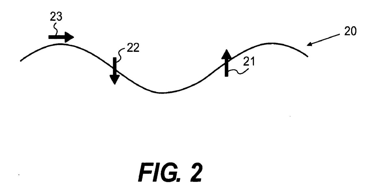
FIG. 2 is a representational
drawing of an ocean wave;
FIG. 3 is a cross-sectionaLview of
an example wave energy converter;

FIGS. 4A-4C are isometric views of
an example wave energy converter;

FIG. 5 is an isometric view of an
example wave energy converter;

FIG. 6 is an isometric view of an
example wave energy converter;
FIG. 7 is a cross-sectional view of
fore and aft floats showing exemplary connecting bearing
shafts;

FIG. 8 is a partial cut-away view
of an embodiment of an example wave energy converter;
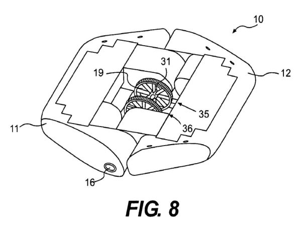
FIG. 9 is an isometric view of an
embodiment of an example wave energy converter;

FIG. 10 is an isometric view of an
example wave energy converter;

FIG. 1 1 is a side view of an
embodiment of the wave energy converter of the present
invention;

FIG. 12 is an isometric view of an
example wave energy converter;

FIG. 13 is an isometric view of an
example wave energy converter;

FIG. 14 is a partial isometric view
of the present inventions;

FIG. 15 is an isometric view of an
example wave energy converter;

FIG. 16 is an isometric view of an
example wave energy converter;
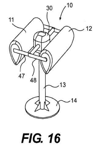
FIG. 17 is an isometric view of an
example wave energy converter;

FIG. 18 is a partial isometric view
of an example wave energy converter; and

FIG. 19 is an isometric view of an
example wave energy converter.

Detailed Description of Invention:
[0010] A wave energy converter 10, shown in FIG. 1, is comprised
of a fore float 11 and an aft float 12. These floats 1 1, 12 are
rotably attached to spar 13. The floats 1 1, 12 are attached
through drive, shafts 18 and 19 (shown in FIG. 3) to a
mechanical rotary system that utilizes the speed or torque to
perform mechanical work (electric generation, water pumping, or
similar function). As seen in FIG. 1, the outer body is
comprised of three components: the spar 13; the fore float 11;
and the aft float 12. The floats 11 and 12 are connected
together by bearing shafts 16 and 17 (the latter of which is
shown in FIG. 3) such that fore float 11 and aft float 12 can
rotate relative to each other. [0011] Water waves 20 are
comprised of rotational particle motions that are grossly
depicted in FIG. 2, heave, which creates vertical up force 21
and vertical down force 22 on bodies exposed to the wave, and
surge which creates horizontal force 23, that a wave imparts to
a body. The magnitude of the rotational forces 22 and 23,
depicted in FIG. 2, are highest at the water's surface, and
diminish as the water depth increases. The floats 11 and 12 of
FIG. 1 experience vertical forces due to the heave of wave 20.
[0012] In FIG. 3, the floats 11 and 12 interconnect through
bearing shafts 16 and 17 so as to permit relative movement
between them. Driveshaft 19 connects float 11 to driveshaft
flange 31 by passing through a motor housing 30 mounted to the
top of spar 13. Rotation between the driveshaft 19 and motor
housing 30 is accommodated by a sealed spar bearing 33. The
sealed spar bearing 33 permits rotation of driveshaft 19
relative to housing 30 but keeps water out of the motor housing
30. In similar fashion, driveshaft 18 connects float 12 to
driveshaft flange 32 by passing through motor housing 30.
Rotation between the driveshaft 19 and motor housing 30 is
accommodated by sealed spar bearing 34, which also seals the
housing 30 so as to keep out water. Driveshaft flange 31 is
mounted to a stator assembly of a generator and driveshaft
flange 32 is mounted to a rotor assembly of a generator.
Alternatively, driveshaft flanges 31 can connect to a rotor
assembly of a first generator and driveshaft flange 32 can
connect to a rotor assembly of a second generator, with the
stator of each being fixedly mounted inside motor housing 30. In
one embodiment, two 80 ton generators are employed.
[0013] As shown in FIG. 3, the float surface area is maximized
by staggering the fore float 1 1 and aft float 12 about an axis
of rotation. The bearing shaft 17 and bearing shaft 16 of FIG. 3
are axis centric on opposite sides of wave energy converter 10.
The placement of these bearing shafts allow for only relative
rotational motion about the axis between the fore float 11 an
aft float 12. While this approach of coupling the fore float 11
and aft float 12 with a bearing system that is independent of
the spar is not essential for function of the system, it allows
for reduction of forces on the spar bearings 33 and 34. [0014]
The spar heave plate 14 shown in FIG. 1 is exposed to smaller
heave forces due to its depth below the water surface. The
placement of that plate below the surface encourages the spar 13
to remain relatively stationary in the vertical direction and
resist the vertical motion of the floats 11 and 12.
[0015] A Power Take Off (PTO) can be mounted in the spar 13 or
floats 11 and 12, and may be mounted in any location as
appropriate for the specific design considerations. A first and
second direct drive rotary generation PTO 35 and 36 are shown in
FIG. 8, but any mechanical power transfer system such as a DDR
generator (previously mentioned), a gear box driven electric
generator, a belt driven electric generator, water pumping
systems, water desalination, pneumatic pumping systems, even
hydraulic pumps, or similar can be used.
[0016] In one embodiment, the first PTO 35 is connected to drive
shaft 19 through flange 31. The second PTO 36 is connected to
drive shaft 18 through flange 32 (not shown in FIG 8). The
relative rotational motion between the spar 13 and the floats 1
1 and 12 drives the first and second PTO to convert wave motion
to useable power. As described earlier, the pitching action of
the spar (surge energy) and the pitching action of the float
(heave energy) are combined to create a net sum that is
complementary and produces a combined speed and force that is
greater then the individual float or spar energies. This net
energy is transferred to the PTO to perform work such as
electrical generation, water pumping, air pumping, or similar
effort.
[0017] In another embodiment, a single PTO can be connected to
drive shafts 18 and 19, such that a rotor (not shown) is
attached to the fore float 1 1 and the stator is attached to the
aft float 12 (or visa- versa). The heave motion of this system
creates relative rotational motion between the floats 11 and 12.
By connecting the PTO only between the floats, the only energy
captured is the energy from the relative motion between the
floats. Hydrodynamic modeling has shown that the motion between
the floats is increased by the addition of the spar system and
its contribution of pitch heave response on the float bodies.
However, an advantage to this arrangement is the increased
rotary speeds and reduced generator costs. Because the stator
and rotor are both . turned in opposite directions by the float
motion, the relative speed between the rotor and stator is twice
that of a spar mounted stator. It is well known in the art of
generator design that increased speed, in general, allows for
reduced cost.
[0018] In another embodiment, two PTO' s can be mounted within
housing 30, or mounted on the surface outside of the spar,
encased in a water tight enclosure on the port and starboard
sides of the system as shown in FIG. 9. In this second
arrangement, PTO 37 has a rotor (not shown) attached to one
float 11 and a stator (not shown) attached to the other float
12. The reverse is true of the PTO 38, which has a rotor (not
shown) attached to float 12 and a stator (not shown) attached to
float 11. Both PTO's are driven by the relative motion between
the floats 11 and 12. The same advantage of increased generator
speed is realized between stator and rotor, because each is
being rotated in opposite directions.
[0019] FIGS. 4A-4C depict various positions of the floats 11 and
12 relative to each other and relative to spar 13 as different
wave conditions are encountered by the wave energy converter 10.
More specifically, FIG. 4A shows a situation in which the spar
13 is essentially perpendicular to the horizon and float 11 and
float 12 have rotated downward. In FIG. 4B, floats 1 1 and 12
have rotated about bearing shaft 16 so as to be roughly
horizontal while spar 13 has rotated off of the vertical
position. In FIG. 4C, float 11 has rotated clockwise, above the
horizon, float 12 has also rotated clockwise, but to an angle
below the horizon, while spar 13 has rotated counterclockwise
about seal bearings 33 and 34. The movement of floats 11 and 12
and spar 13 being in reaction to wave forces acting upon them,
with each movement leading to the potential conversion of wave
energy by wave energy converter 10. Floats 11 and 12 will rotate
up and down with each wave's incoming crest and trough,
experiencing rotational motion with respect to the spar 13 due
to heave forces acting on the floats.
[0020] The floats 11 and 12 of FIG. 1, experience horizontal
forces 21 and 22 due to wave surges shown in FIG. 2. The floats
11 and 12 are allowed to rotate with respect to the spar 13.
Figure 4B depicts the floats 11 and 12, and spar 13 being pulled
by surge forces to the right. The surge forces are minimal at
the bottom of the spar 13 and at the heave plate 14. This
difference in horizontal loading between the top of spar 13 and
the bottom of that spar causes a moment about the spar body, so
as to cause the spar to pitch right as depicted in FIG. 4B. The
system is ballasted and designed to achieve a desired pivot
point 15 on spar 13, this pivot point affects the speed of the
pitching action and the amount of power absorbed. The
optimization of this pitching action is the designers'
prerogative based on design priorities upon reading and
understanding this disclosure, but ideally the pivot point 15 is
between the motor housing 30 but above the heave plate 14. As
the spar 13 pitches fore and aft, the spar 13 and floats 11 and
12 experience relative rotational motion.
[0021] In both cases, surge and heave forces/the floats 11 and
12 rotate about spar 13 with speed and torque to transmit power
through drive shafts 18 and 19. The net affect of these heave
and surge driven rotary motions is hypothesized and numerically
modeled to be complementary (not opposing) in direction and
force. The synthesis of these two motions is depicted in FIG.
4C, where it is shown that the net effect of both heave and
surge forces will act on the wave energy converter 10 and that
converter will absorb power from both modes (heave and surge) of
wave motion. The system may work in either mode of operation to
capture energy by using heave motion or surge motion as
depicted, or both.
[0022] As an electrical generating system, a reduced cost of
energy (CoE) is expected to be an advantage over other
approaches. The wave energy absorber has the potential to be
half the size of a competing wave energy converter of the same
power rating. That size reduction reduces capital costs and CoE.
The CoE is further reduced by reducing the capital expenditure
of the generator by optimizing the electromagnetic design using
a large diameter generator when low-speed high-torque rotary
motion is employed. Operating and maintenance costs are reduced
by the systems operational design; there are minimal moving
parts, and the parts that do move do so fluidly, with the
incoming waves, so as to reduce the affect of snap loading often
experienced by marine deployed bodies. This construction and
approach reduces repair time and cost. The speed of rotation and
driving torque are both increased by the extraction of both
heave and surge energy. r Increasing the speed of body motions
helps to reduce generator capital costs and the system
components may be designed to satisfy this priority. In some
methods described in this disclosure, reliability is improved by
the elimination of all intermediate conversion stages. The WEC
Survivability is another advantage of this system. The combined
effect of the design results in a fluid motion of the wave
converter in the ocean which reduces structural loading, reduces
mooring loading, and accommodates for tidal variation.
[0023] These methods described utilize rotary motion from a WEC
to allow for a point absorber design that captures the heave and
surge energy components of the incoming wave energy. By
capturing both the surge and heave component, the maximum
possible energy capture width of the wave energy device is
[lambda]/[pi] (where [lambda] = wave length) as compared to
[lambda]/2[pi] for a device that captures only the heave
component. This improvement in capture width is expected to
reduce the size and cost of the wave energy converter. The exact
generator, pump, or rotary mechanisms for this application is
not essential to the claims of this invention because it is
applicable to any mechanism or system that is driven by a rotary
shaft.
[0024] In FIGS. 5 and 6, the spar 13 is shortened and the damper
plate 9 is connected to the spar 13 using a cable or chain 31.
The shortening of the spar allows for increased pitch motion and
increased relative speed between float and spar in the surge
mode of operation. The heave plate 14 connected through the
cable 31 still allows for heave reaction force in the heave mode
of operation and allows the damper plate 9 to be lower in the
water to increase the effectiveness of the damper plate
operation. A shorter spar 13 also reduces the overall system
cost, optimization of power absorption, and optimization of PTO
speed, lowers the damper plate position and increases heave
response. [0025] The spar 13 is designed to be relatively fixed
in heave so that it resists the upward and downward heave motion
of the floats. The spar 13 may also be designed such that it has
a ballast chamber that varies the spar buoyancy between either
positively buoyant when the wave trough is above the spar, or
negatively buoyant when the wave crest is above the spar. Spar
13 is designed to transition between positive buoyancy and
negative buoyancy, while maintaining the buoyancy to avoid
sinking. This condition causes the heave motion of the spar 13
to move opposite (180 degrees out of phase) to the heave motion
of floats 11 and 12. This diving and rising spar design is
accomplished using a compressible ballast chamber in the lower
section of the spar (not shown). When the wave crest is over
spar 13, the higher pressure from the wave causes the ballast
chamber to compress and causes the spar 13 to sink until the
floats reach equilibrium buoyant state. Conversely, when the
wave trough is over spar 13, the pressure on the buoyancy
chamber is reduced, the ballast chamber expands, and spar 13
rises until the floats 11 and 12 reach an equilibrium buoyant
state with the spar 13. This diving and rising action amplifies
the range of motion between floats 11 and 12 and spar 13, and
can be used to improve the wave converter performance.
Additionally, it has been shown that proper ballast location in
the spar can increase captured power and can also be used to
optimize relative speed between the spar and floats.
[0026] A challenge to proper operation of this system is the
control of directionality. The power extraction efficiency is
improved by proper orientation of floats 11 and 12 and the
rotation axes with respect to the incoming wave front.
Generally, performance is maximized when the axis of rotation is
parallel to the incoming wave front, and minimized when the axis
of rotation is perpendicular to the incoming wave front.
Depending on the incident wave energy the system performance can
be optimized and stabilized by changing the float orientation
with respect to the incoming waves. It is recognized that in
very energetic sea states, it may be desirable to decrease
performance by changing the float orientation to a less
efficient position.
[0027] Directionality is affected by direction of water flowing
past the device. The mean drift current of the incident wave
climate is one source of current flow acting on the buoy.
Another source of water flow acting on the body is the
predominant ocean current acting on the buoy body. Wind acting
on the buoy body above the water surface will also affect
directionality. Directional vanes 39, shown in FIG. 10, can be
used to channel water on the underside of floats 1 1 and 12.
These vanes can be installed on the fore float 11, the aft 12,
or both, depending on the preferred affect. Directional vanes 39
will cause floats 11 and 12 to align with the direction of flow
acting on them. As depicted in FIG. 10, the directional vanes 39
are shrouded by the outer hull of the floats. By shrouding the
directional vanes 39, the directional effects from the wave
action will be increased due to the wave acting from under the
float body, while the effects from ocean current will be
minimized. The size, length and aspect ratio of the directional
vanes 39 may be varied to increase or decrease the magnitude of
the effect of the vanes on directionality. Directional vanes 39
can alternatively be used on the aft float 12 only to provide a
rudder effect to keep the device pointed into the wave.
[0028] In another embodiment, a rudder 40, shown in FIG. 11 can
be used to control float orientation in the wave. More than one
rudder may also be used. The rudder may be positioned in all 360
degrees of rotation. The rudder is statically positioned,
manually controlled, or automatically controlled using existing
technology similar to an automatic pilot used on numerous
vessels. The control for the rudder takes into account the
prevailing wave direction, prevailing currents, wind, and drift
and sets the rudder to maintain the desired buoy direction.
[0029] In another embodiment, a two point mooring system is used
to control directionality. This system may be slack moored as
depicted in FIG. 12. In FIG. 12, a slack mooring line 41
attaches to bearing shaft 16 and a second mooring line 42
attached to bearing shaft 17. A mechanism such as a chain winch
43, shown in FIG. 14, can be used to shorten or lengthen either
mooring line. This will create a rotation on the float such that
can be oriented in the desired direction.
[0030] In another embodiment, a three point mooring system is
used to control directionality. This system may be slack moored
as depicted in FIG. 13. Mooring lines 41, 42 and 44 can attach
to the heave plate 14 of converter 10 by conventional means. In
one embodiment, mooring lines 41 and 42 form a common connection
point to the heave plate 14 through a chain winch 43 as shown in
FIG. 14. By adjusting the direction of chain as shown in FIG.
14, the heave plate 14 can be forced to rotate into the desired
direction so as to orient the converter 10 in the desired
direction.
[0031] In another embodiment, the top surface area of float 1 1
and float 12 in FIG. 1 are covered with an array of solar panels
52 and 53. This is of particular interest due to the large and
un-blocked surface area that is in direct line of sight with the
sun. Complementing the wave power with solar power provides for
a more continuous power delivery from each WEC especially when
wave energy is low during summer months.
[0032] The geometry of system components can be optimized for
use on different bodies of water during different seasons based
on many factors. The floats 11 and 12 may be constructed with a
narrow width to length ratio, or it might have a wide aspect
ratio. Float geometry is optimized for wave height, wave period,
seasonal wave spectral density, power capture, and
directionality considerations. Float shape is not limited by the
geometry depicted and may take on a more curved disc shape. The
floats 1 1 and 12 might also be cylindrical or rectangular in
shape. Similarly, the diameter or length of the spar 13 may be
altered for performance enhancements.
[0033] Depending on the wave conditions, for example the
distance between a wave peak and a wave trough, it may be
advisable to separate floats 11 and 12, using adjustable arms as
shown in FIG.17, alter the shape of the floats as shown in FIG.
16, re-orient the floats as shown in FIG. 17 and FIG. 18, add
additional damper plates as shown in FIG. 19, or, in shallower
waters, embed the spar in the sea floor.
[0034] With regard to FIG. 16, it should be noted that the side
profile of floats 11 and 12, shown here as a tear-dropped shape,
can be mounted to arms 47 and 48, respectively, such that they
can rotate about of center axis of the arms. The shape of the
float is not limited. Float shape is to be optimized for
hydrodynamic performance. These floats can include cylinders,
squares, triangles and any combinations of curves. Nor is the
rotation axis limited, but can be varied. The rotation of the
floats changes the hydrodynamic performance, including water
plain stiffness of the float, the float's center of gravity, and
float free-board. Variable ballasting of floats 1 1 and 12 could
provide additional hydrodynamic optimization.
[0035] As shown in FIG. 17, the length of arms 47 and 48 can
vary to suit the water conditions or to control the amount of
energy being absorbed. In this embodiment of a wave energy
converter, floats 11 and 12 are rotably connected to arms 47 and
48, respectively, via mounting 49 and 50, respectively. The yaw
rotation of the floats allows the floats to rotate so as to be
perpendicular to the axis of rotation of the PTO in housing 30.
The floats can also rotate on arms 47 and 48 so as to be
parallel with the axis of rotation of that PTO, or somewhere in
between the parallel and perpendicular positions. Indeed, the
orientation of the two floats can differ as shown in FIG. 17.
The floats can be automatically or manually adjusted to control
the amount of energy being absorbed from a wave.
[0036] As shown in FIG. 18, it is also possible to add a rudder
51 to the bottom of heave plate 14 in lieu of, or in addition
to, directional vanes 39 of FIG. 10, rudder 40 of FIG. 11, or a
combination of the two. Rudder 51 may be automatically or
manually positioned to control the direction of the wave energy
converter relative to the direction of wave travel. [0037] As
shown in FIG. 19, it is also possible to suspend a damper plate
52 from heave plate 14 to stabilize spar 13. For the same
reason, it is also possible to suspend a damper plate 52 from
damper plate 9, or a second heave plate (not shown) from heave
plate 14, or a combination of these plates to stabilize the
operation of the wave energy converter of the present invention.
[0038] As can be readily understood from the foregoing
description of the invention, the preferred structure and method
of operation have been described, but other structures and
approaches can be substituted therefore without departing from
the scope of the invention.