http://www.xconomy.com/boston/2012/06/21/juliet-marines-ghost-ship-emerges-from-stealth-startup-gears-up-for-war/?single_page=true%E2%80%9D
6-21-2012
Juliet
Marine’s “Ghost” Ship Emerges from Stealth Startup, Gears
Up for War
by
Gregory T. Huang
About an hour north of Boston, in a city by the sea, there’s a
project underway to reinvent the marine industry. More
specifically, the marine defense industry.
Imagine a boat that moves through the water differently from any
other boat in existence. It uses “supercavitation”—the creation
of a gaseous bubble layer around the hull to reduce friction
underwater—to reach very high speeds at relatively low fuel
cost. Its speed and shape means it can evade detection by sonar
or ship radar. It can outrun torpedoes. Its fuel efficiency
means it has greater range and can run longer missions than
conventional boats and helicopters.
Now imagine that this vessel has already been built and tested.
It “flies” through the water more or less the way it was
designed to—like a high-tech torpedo, except part of the craft
is above water—and it can be maneuvered like a fighter plane.
“It’s almost as much an aircraft as it is a boat,” says its
inventor, Gregory Sancoff, the founder and CEO of Juliet Marine
Systems, a private company in Portsmouth, NH.
The vehicle, dubbed the “Ghost,” is the first of its kind and is
garnering attention from organizations like the U.S. Navy, Coast
Guard, defense contractors, and foreign governments—as well as
hackers in foreign countries, who are presumably trying to
figure out how it works. Juliet Marine Systems has received
about $10 million in total funding, about half of which comes
from its founder and private investors. The startup’s
institutional investor is Avalon Ventures, a VC firm with
offices in the San Diego and Boston areas.
Until recently, the project was kept under wraps because of
secrecy orders from the federal government. But this summer,
Sancoff says, the Ghost—which looks like something out of Star
Trek (see photos)—will be ready for prime-time deployment. His
team of 16 employees is working on integrating weapons and
sensors for military missions. “We have a fully functional,
basically go-to-war boat right now,” Sancoff says.
The question is, does it really work? And, more to the point,
can it be used for missions safely, reliably, and effectively?
If the answer is yes—and that’s a big if, from an outside
perspective—one could imagine a squadron of Ghosts being
deployed to the Persian Gulf, say, to defend warships and other
interests against “swarm” attacks by small boats, Sancoff says.
The vessel also could be used against pirate attacks, for Coast
Guard rescue missions, or to transport workers to and from oil
platforms. The technology might have much broader uses, too—in
global cargo shipping, for example, to reduce fuel costs, or for
commercial jet skis. (Wacky as it is, the concept is not as
far-fetched as, say, a submarine that can also fly.)
But to get a better sense of the ship’s real prospects—and the
company’s—let’s consider the whole story.
From Medical to Marine Tech
Sancoff, 55, is a prolific inventor and serial entrepreneur who,
I’m told, takes engineering magazines to bed. He grew up in a
military family and went to high school in Lawrence, MA. As a
kid, he lived on Army bases and says he remembers saluting the
flag when he got out of the car. Sancoff never served in the
military, but that’s probably because he was too busy inventing
stuff.
He started his first company when he was 18—a machine shop for
doing rapid device-prototyping for other businesses. He sold
that and headed west to San Diego in 1982, at age 25. As a
consultant, he became an expert in medical devices, including
systems for delivering intravenous fluids, collecting health
data, and other applications. He started a new company, Block
Medical, and sold it for $80 million in 1991. His next company,
River Medical, was based around a new kind of drug-delivery
device for hospitals. River acquired IVAC, a medical-device firm
divested from Eli Lilly, and ended up being sold to Advanced
Medical (IMED) for $400 million in 1995.
Sancoff’s next big project was to start Onux Medical, a surgical
tech company based in New Hampshire. It was there, in 2000, that
he first got inspiration for Juliet Marine and the Ghost ship.
Sancoff was sitting in a conference room when he heard the
U.S.S. Cole had been attacked off the coast of Yemen by a small
boat loaded with explosives. Seventeen U.S. sailors had been
killed and many more wounded. He sat there in disbelief as he
realized a billion-dollar warship had nearly been sunk by a
couple of guys in a raft.
Juliet Marine would derive its name from a U.S. Navy “war games”
exercise held in 2002. At $250 million, it was the most
expensive exercise in Naval history. “Fleet Battle
Experiment—Juliet” involved warships parked off the coast of
California and a series of simulated small-boat attacks. The
results of the simulation were grim: more than 20,000 deaths and
massive losses to the fleet, in a Persian Gulf scenario. Yet,
Sancoff says, the Navy hasn’t done anything in the past 10 years
to guard against such attacks, other than work on targeted
rocket systems.
“When you’re an entrepreneur, there has to be an overwhelming
reason why you do it,” Sancoff says. “That was it for me.”
He saw a big opportunity—if only he could design a ship fast
enough and maneuverable enough to intercept attackers before
they could get close to big ships or shorelines. He had raced
hydroplanes as a teenager—probably could bulls-eye womp rats,
too (sorry, Star Wars joke)—so he had an intuitive feel for what
it might take.
Which brings us to supercavitation. It’s an old idea. During the
Cold War, the Russians developed a torpedo called the Shkval
(“squall”) that could go more than 200 mph — five times as fast
as a conventional torpedo — using a rocket engine and air
ejected in front to produce a gaseous bubble completely
enveloping the projectile. That reduces the friction between the
hull and its surroundings by a factor of about 900, enabling
superfast travel. Yet rocket-propelled torpedoes have downsides
in performance and reliability; the sinking of the Russian
submarine Kursk in 2000 is rumored to have been caused by a
malfunctioning Shkval.
Meanwhile, the U.S. Navy and others reportedly have been working
on a next-generation supercavitating torpedo since at least the
1990s. And in recent years, the Defense Advanced Research
Projects Agency (DARPA) ran a program, called Underwater
Express, to design a supercavitating submarine. There is also
interest in using the concept to improve fuel efficiency for oil
tankers, ferries, and other large ships, typically by creating
air bubbles at the front of the hull. As of yet, however, nobody
has publicly demonstrated a successful supercavitating craft.
To that end, after leaving Onux (which was bought by Bard in
2004), Sancoff spent several years doing research on his own and
incorporated Juliet Marine in 2008. By June of last year, using
$5 million of mostly his own money, his team had built a fully
functioning prototype — Sancoff prefers the term
“pre-production” vehicle. And earlier this year, he secured an
additional $5 million from Avalon Ventures, the VC firm that
invested in his last two companies.
At a Bay Area event in March, Kevin Kinsella, the Avalon partner
on the deal, spoke glowingly of River Medical in particular. “We
got 10x [return] in 18 months, and I only had to go to four
meetings. An ROI of 2.5x per board meeting is fantastic,” he
said. (Onux didn’t cash out quite as well, but it still worked
out fine.)
After seeing firsthand what Juliet Marine built with $5 million,
Kinsella said, “If you were taken around by a handler from
Lockheed or Grumman or Northrop or any of them, and they told
you, ‘We developed this on $150 million,’ you wouldn’t bat an
eye.” He told the story of a meeting with Avalon and its fund
investors. Someone asked Sancoff, “How did you get to be so
capital efficient in your company?” Kinsella relays, “He leaned
on the podium and said, ‘Because it was my money.’”
Not Your Grandfather’s Boat
OK, so here’s how it works, according to a patent filing (see
diagram, below). The main compartment of the Ghost vessel, which
houses the cockpit and controls, sits above the water in between
two torpedo-shaped pontoons or “foils,” which are submerged and
create all the buoyancy and propulsion for the craft. The angle
of the struts that connect the foils to the command module is
adjustable — so the craft can ride high in choppy seas and at
high speeds (so waves don’t hit the middle part), and low in
calm water and at lower speeds.
“We’re basically riding on two supercavitating torpedoes. And
we’ve put a boat on top of it,” Sancoff says.
At the front of each foil is a special propeller system that
pulls the craft forward. The propellers are powered by a
modified gas turbine — a jet engine — housed in each foil; the
air intake and exhaust ports for the engines are in the struts.
As the ship moves through the water, the motion of the
propellers creates a thin layer of bubbly water vapor that
surrounds each foil from front to back, helped along by the
presence of “air trap fins” that keep the vapor in contact with
the hull (and keep liquid away from the hull). The vapor is what
constitutes the supercavitation, so the foils can glide
effortlessly through the bubbles.
“The key is the propulsion. You have to have a lot of power at
the right location in this vessel,” Sancoff says. Exactly how
this is done is a trade secret. But the propulsion system, which
he says generates 30 percent more thrust than any other
propeller-based system, essentially “boils water underwater and
generates steam vapor.” (I take this to mean the pressure
directly behind the propeller blades is so low that the liquid
water there “boils” off and becomes a gas—hence the bubbles.)
After doing some digging in the literature, I asked Sancoff
whether what’s in the patent filing is really how it works — in
terms of how the Ghost creates its mysterious supercavitation.
His answer: “No.” (OK, so there’s more to the story here. But
you know when you’re supercavitating, he says, because the
engine efficiency actually improves as you go faster.)
In any case, the overall design makes the craft go fast, but
Sancoff isn’t making any public claims yet about exactly how
fast. “We don’t talk about speed, how many weapons [it can
carry], or how far we can go,” he says. Yet its rumored speed is
at least 80-100 knots — over 100 mph. That’s not going to
challenge the top speedboat records — there have been hydroplane
efforts (riding on the water surface) that have exceeded 200 mph
(174 knots) and even 300 mph (261 knots), some with fatal
results—but the Ghost is faster than any previous underwater
vehicle, Sancoff says.
What’s more, he says, the Ghost provides a much smoother ride
than what Navy SEALs are used to; many of them blow out their
backs from the bumpiness of their boats, he says. “Our boat does
not have impact from the waves. We cut through the wave,”
Sancoff says. “That is critical science.”
Hydrodynamics experts I’ve talked to say the main challenges of
such a craft are controlling it, stabilizing it, and making it
quiet. Going superfast in a straight line might be doable, they
say, but any sort of turning or maneuvering must be done very
carefully, because if the bubble layer distorts or breaks down
at high speeds, tremendous water forces will come to bear on the
foils, which can be catastrophic.
To steer itself through the water and maintain stability, the
Ghost uses four movable flaps on the front of each foil and four
on the back of each foil, for a total of 16 flaps. (The flaps
reach through the thin bubble layer into the surrounding water.)
The struts are adjusted to keep the command module out of the
water, and the foils stay submerged, so waves at the water
surface should only hit the struts, which have a small
cross-section.
“It’s computer controlled, like a modern F-18,” Sancoff says.
“We’re boring what looks like two wormholes underwater, and
we’re flying through foam.” Sancoff himself has been
test-driving the ship over the past couple of years. “I have
been learning an entirely new craft since then. It’s a totally
new experience,” he says. “Just because you drive Grandpa’s
boat, you’re not going to drive this one. It’s more like a
helicopter.”
As for the craft’s audio profile, Sancoff is proud of its
“silent propulsion” system that includes a sophisticated muffler
system for the engines. You can’t hear it from 50 feet away, he
says.
Coming Out of the Night
With any grand invention like this, some outside experts are
going to be skeptical. “I wouldn’t say it’s not going to work.
But I have concerns,” says Gary Balas, head of the department of
aerospace engineering and mechanics at the University of
Minnesota. Balas is an expert in flight and underwater control
systems, but his main objection is that the propulsion system of
the Ghost, with its forward propellers, is very unusual for a
supercavitating craft. The typical approach, as in the Russian
torpedo, is to propel the craft from behind and eject gas and/or
use a blunt shape in the front to create an air cavity around
the craft. “I don’t see how they’ll achieve what they expect to
achieve,” Balas says. “And I don’t see how they’ll control the
altitude and the yaw of the vehicle.”
His colleague, Roger Arndt, also a professor at the University
of Minnesota, is an expert in fluid flow and cavitation. He has
doubts about the Ghost propulsion method as well. In fact,
cavitation bubbles are normally bad for propellers and can cause
serious damage. But there is a type of propeller, with
wedge-shaped blades, that produces supercavitation in high-speed
racing boats; presumably this is similar to Ghost’s propellers.
But in this case, Arndt says, “I am dubious about the
application of supercavitating propellers.” (To be fair, Sancoff
said that what’s in the patent filing isn’t quite how it works.)
Other experts on supercavitation declined to comment for this
article. Sancoff emphasizes that the project has a lot of
sensitive aspects to it, in terms of national security, so
people who know about it aren’t talking. And he claims that
Juliet Marine’s website is getting “attacked” 350 times a month
by hackers, mostly in foreign countries.
In any case, the current vehicle — which resides under tight
security at Portsmouth Naval Shipyard (“a great asset” for a
startup to be able to rent space in, he says) — holds 18 people
and weighs some 60,000 pounds fully loaded; the underwater part
of the vessel is 62 feet long. Sancoff says it can be launched
from any beach. “A group of these boats coming out of the night
in the Persian Gulf, armed with torpedoes, would be undetectable
to large ships,” he says. “Ghost cannot be hit by a torpedo. You
would have to shoot it with a gun.”
Not surprisingly, Sancoff sees an urgent military need for his
craft. The Navy loses sleep about swarm attacks and security in
the Strait of Hormuz (which runs between Iran, United Arab
Emirates, and Oman) and other strategic waterways, he says. Yet
it hasn’t moved quickly enough to do anything about the threats.
“We talk with the Navy weekly,” he says. “We believe the U.S.
could use a hundred of these boats right away.” At a price of
$20 million per boat — fully loaded with electronics, radar, and
so forth — that “provides us with a billion-dollar market
opportunity for coastal and fleet protection,” he says.
Meanwhile, the U.S. State Department has granted Juliet Marine
permission to talk with the governments of Israel and UAE, which
both have marine security concerns. The company says it is
currently building a manufacturing facility near Portsmouth, in
anticipation of ramping up to sell Ghost ships to customers.
Sancoff adds that Juliet Marine is planning to build two more
versions of the ship this fall, using what he calls “the final
configuration.”
And while the startup strives to gain full acceptance from the
U.S. Navy and other potential defense customers, it is “working
on weaponizing” the craft, says Sancoff. “The vehicle’s done.
Now it’s time to get mission modules complete.” That means
mounting torpedoes, machine guns, radar, mine-detection systems,
and other sensors onto the craft — and making sure it all works
the way it’s supposed to.
That remains to be seen, of course. But if it performs as
advertised, Juliet Marine could end up playing a vital role in
global security on the high seas. “That’s the beautiful thing
about being an entrepreneur,” says Sancoff. “You take a risk
with it.”
SOVIET SHKVAL
TORPEDO
http://www.nhbr.com/news/951153-395/n.h.-entrepreneur-puts-his-faith-in-a.html
Friday, February 24, 2012
N.H.
entrepreneur puts his faith in a Ghost
By
Michael McCord
'We plan to build a
major company here,' says Greg Sancoff, founder of Juliet Marine
Systems.
When entrepreneur Greg Sancoff takes his watercraft out for a
test drive on the Piscataqua River, the 75-foot long vessel
draws quizzical looks from people who see it. There are good
reasons for the double-take stares.
The sleekly angled, supercavitating Ghost looks like it just
arrived from the set of a Hollywood science fiction movie. In
reality, the Ghost has the potential to play a vital role in
protecting American Navy vessels in volatile regions of the
world, such as the current, headline-making tensions in the
Persian Gulf.
Ghost is a high-speed attack craft - Sancoff calls it a modern
version of the PT Boat - specifically designed to protect vital
waterways like the Straits of Hormuz and to counter threats to
commercial shipping, such as piracy, which is increasing in many
areas of the world.
Sancoff says the Ghost has been compared to an attack helicopter
on the water. "Ghost would be a very important and
cost-effective security tool to exert a constant presence in
this troubled region," he said.
For almost three decades as a successful entrepreneur in the
medical devices industry, Sancoff was accustomed to taking
risks. He has founded and sold four companies totaling more than
$100 million. But his latest venture, Portsmouth-based Juliet
Marine Systems, required a combination investment of patriotism,
personal finances and innovative research and development far
beyond anything he had done before.
"By far this is the most fulfilling thing I have ever done,"
Sancoff said.
Fast, fuel-efficient
What makes the Ghost unique is that it was developed entirely on
spec in less than four years, unprecedented for a potential
"game-changing" defense technology, he said.
While other weapons and defense industry programs get government
approval and research funding and then embark on lengthy
development and deployment process, Juliet Marine Systems
bypassed all of that.
"It was the fastest way to get it done. We didn't get involved
with government research institutions because it would have
slowed us down," Sancoff said of his personal
multimillion-dollar backing of the Ghost. "Look at Silicon
Valley and the most efficient way to develop new technology. We
did this in a think tank environment just as companies like
Apple do."
Juliet Marine Systems created and built the Ghost prototypes in
secrecy at the Portsmouth Naval Shipyard with only 10 full-time
engineers and scientists.
The Ghost could have been deployed already if the federal
government had not put a secrecy order in place for more than 18
months on some of Juliet Marine's patents. Sancoff said this
prevented extensive testing during that time because the craft
couldn't be seen in public.
Despite the delay, Sancoff has built it and the Navy and
maritime industry have come to see it.
What they are seeing is a very fast, fuel-efficient craft that
can barely be detected by radar and can stay on patrol for a
very long time (because it's now classified material, Sancoff
can't say exactly how fast the craft can go and how long it can
go between refueling its gas turbine jet engines.)
It's fast because it has been designed to fly through an
artificial underwater gaseous environment that creates 900 times
less hull friction than water. Sancoff also said the Ghost has
22 special systems that give the craft stability.
Juliet Marine is currently in discussions with defense companies
to implement an off-the-shelf weapons solution. In keeping with
his entrepreneurial roots, Sancoff will not make it a
overthought process.
"We do not have to reinvent the wheel," he said. "There are
several systems today that would provide ample power and fit the
mission characteristics."
'Call to action'
During a recent visit to the Pentagon, a high-ranking naval
research officer asked Sancoff, "Why did you do this?"
For Sancoff, it was a decades-long journey of finding a solution
and "giving something back to my country."
The genesis, Sancoff explained, came in October 2000 when the
naval destroyer USS Cole was attacked and 17 sailors killed by
an explosive-laden small craft guided by al-Qaeda terrorists in
Yemen. He became focused on a solution for fleet security from
attacks that are akin to land-based IEDs, or improvised
explosive devices.
The terrorist attacks of Sept. 11, 2001, provided another burst
of motivation. Finally, there was a major naval fleet exercise
in 2002 to determine security from small boat attacks. The
exercise was code-named Juliet, which provided the name for
Sancoff's company, and the result showed too many
vulnerabilities.
"This was my call to action," he said.
He said he began to do voluminous research, and when he sold his
Hampton-based company, Onux Medical, in 2004, it became his
full-time quest to create a new type of company to work at rapid
deployment speed.
"My wife Jennifer talked about this extensively. The idea was so
strong that we decided to go forward and develop these ideas,"
Sancoff said about the decision to finance the
multimillion-dollar startup with their money. "I have been very
successful and wanted to give something back to my country."
The company was officially started in late 2007, and major
research and development began in 2008 after the space at
Portsmouth Naval Shipyard was secured. "We have a very small
team of people, and they are very smart at what they do. This
has allowed us to have such a rapid turnaround time," Sancoff
said.
The company's board members include two retired U.S. Navy
admirals and former U.S. Sen. John E. Sununu of New Hampshire.
Sancoff said construction of the Ghost was enhanced by the work
of many regional machine shops, and he believes the Seacoast
region should become the site for manufacture of the Ghost and
other marine-related systems.
In fact, the company has begun to add its engineering and
scientific staff in anticipation of both commercial and military
contracts for the Ghost.
"It's up to them (users) just how fast they want to adapt this
new technology," Sancoff said. "We have been in discussions
about making a 150-foot version. There are so many applications,
even down to pleasure craft size. We plan to build a major
company here."
FLEET
PROTECTION ATTACK CRAFT AND UNDERWATER VEHICLES
US2012097086
REFERENCE TO PENDING PRIOR PATENT
APPLICATIONS
[0001] This patent application:
[0002] (1) is a continuation-in-part of pending prior U.S.
patent application Ser. No. 12/485,848, filed Jun. 16, 2009 by
Gregory E. Sancoff et al. for FLEET PROTECTION ATTACK CRAFT
(Attorney's Docket No. JULIET-0102), which in turn claims
benefit of:
(i) prior U.S. Patent Application Ser. No. 61/132,184, filed
Jun. 16, 2008 by Gregory Sancoff for FORCE PROTECTION ATTACK
CRAFT (Attorney's Docket No. JULIET-1 PROV); and
(ii) prior U.S. Patent Application Ser. No. 61/200,284, filed
Nov. 26, 2008 by Gregory Sancoff et al. for FLEET PROTECTION
ATTACK CRAFT (F-PAC) (Attorney's Docket No. JULIET-2 PROV);
[0005] (2) claims benefit of pending prior U.S. Provisional
Patent Application Ser. No. 61/374,923, filed Aug. 18, 2010 by
Gregory E. Sancoff for SUPERCAVITATION AIR CHANNELS FOR BUOYANT
TUBULAR FOIL (Attorney's Docket No. JULIET-7 PROV); and
[0006] (3) claims benefit of pending prior U.S. Provisional
Patent Application Ser. No. 61/374,940, filed Aug. 18, 2010 by
Gregory E. Sancoff for TORPEDO EMPLOYING FRONT-MOUNTED
COUNTER-ROTATING PROPELLERS AND STEERING SPOILERS (Attorney's
Docket No. JULIET-9-2-PROV).
[0007] The five above-identified patent applications are hereby
incorporated herein by reference.
FIELD OF THE INVENTION
[0008] This invention relates to marine vessels in general, and
more particularly to high-speed attack and reconnaissance craft.
BACKGROUND OF THE INVENTION
[0009] The terrorist attack on the guided missile destroyer USS
Cole in Aden harbor in 2000 provided a devastating example of
what a small group of terrorists can do to a modern warship with
minimal resources-in the case of the USS Cole, two terrorists in
a small boat carrying a few hundred pounds of explosives came
close to sinking a billion dollar warship.
[0010] The success of the attack on the Cole has given rise to
another, even more disturbing concern-that a large number of
high speed boats, each packed with explosives and manned by
suicide bombers, could create a "small boat swarm" which could
overwhelm the defenses of a warship, particularly in restricted
waters where reaction time and maneuverability may be limited.
Indeed, recent wargame simulations suggest that such swarm
tactics could prove extremely effective against naval battle
groups operating in the narrow waters of the Persian Gulf.
[0011] It is currently believed that such "small boat swarm"
tactics are best countered with fast, similarly-sized,
highly-maneuverable and heavily-armed attack craft which can
establish a defensive perimeter at a safe distance from the
naval battle group. To this end, appropriately-outfitted
Zodiac-type craft have already been deployed for this purpose.
However, experience has shown that Zodiac-type craft are only
practical in the relatively calm waters of a harbor. This is
because operating Zodiac-type craft at high speed in the
turbulent waters of the open sea imposes excessive physical
stresses on the crews that can only be withstood for short
periods of time. Furthermore, the defensive perimeter should,
ideally, be established at a substantial distance from the
battle group (e.g., at least 10 miles out), in order to give the
battle group sufficient time to react in the event that any of
the small boat swarm should penetrate the defensive perimeter
established by the Zodiac-type craft. However, due to their
light construction, limited operating time at high speeds, and
limited fuel-carrying capacity, Zodiac-type craft are not
capable of maintaining a reliable defensive perimeter so far out
from the battle group. In practice, with Zodiac-type craft, the
defensive perimeter must generally be maintained much closer to
the battle group, with the consequent loss of reaction time.
[0012] It has been suggested that attack helicopters might be
used to protect a naval battle group when it is at sea or at
anchor. However, attack helicopters generally have relatively
limited range and, perhaps more importantly, relatively limited
sortie time, which effectively prevents them from maintaining a
reliable defensive perimeter a substantial distance out from the
battle group. Furthermore, attack helicopters generally have
substantial radar, infrared and visual "signatures", thereby
making them relatively easy to detect and target.
[0013] Thus, there is a need for a new and improved fleet
protection attack craft which can be used to maintain a
defensive perimeter a safe distance out from a naval battle
group. In this respect, it should be appreciated that such a
craft should be small, fast, highly-maneuverable and
heavily-armed. Furthermore, the craft should provide a stable
platform even when running at high speed in substantial ocean
swells, whereby to minimize physical stress on the crew and to
provide a stable weapons platform. Further, the craft should be
capable of remaining on station for a substantial period of
time, in order to maintain a reliable defensive perimeter at a
safe distance from the battle group.
[0014] There is also a need for a new and improved craft which
can be used for reconnaissance, and/or to deliver small teams of
special forces behind enemy lines and/or to extract the same.
Thus, the craft should also be capable of "stealth mode"
operation, i.e., it should have small radar, infrared, visual
and noise signatures, thereby making it difficult to detect and
target.
SUMMARY OF THE INVENTION
[0015] These and other objects of the present invention are
addressed by the provision and use of a novel fleet protection
attack craft. The novel attack craft is small, fast,
highly-maneuverable and heavily-armed. The novel attack craft
provides a stable platform even when running at high speed in
substantial ocean swells, whereby to minimize physical stress on
the crew and to provide a stable weapons platform. And the novel
attack craft is capable of remaining on station for a
substantial period of time, in order to maintain a reliable
defensive perimeter at a safe distance from a naval battle
group. Thus, the novel attack craft provides an effective means
for defending against a "small boat swarm", by establishing a
defensive perimeter at a safe distance from the battle group and
thereby permitting the interception, identification, warning
and, if ultimately necessary, destruction of hostile boats long
before they can approach the battle group.
[0016] In addition, the novel attack craft is capable of
"stealth mode" operation, i.e., it has small radar, infrared,
visual and noise signatures, thereby making it difficult to
detect and target. Thus, the novel attack craft also provides an
effective means for conducting reconnaissance and/or for
delivering small teams of special forces behind enemy lines
and/or for extracting the same.
[0017] In one form of the present invention, there is provided a
marine vessel comprising:
[0018] a command module;
[0019] first and second buoyant tubular foils; and
[0020] first and second struts for connecting the first and
second buoyant tubular foils to the command module,
respectively;
[0021] wherein the first and second buoyant tubular foils
provide substantially all buoyancy required for the marine
vessel;
[0022] wherein the first and second struts are pivotally
connected to the command module and pivotally or fixedly
connected to the first and second buoyant tubular foils,
respectively; and
[0023] wherein the first and second struts comprise
substantially rigid planar structures.
[0024] In another form of the present invention, there is
provided a marine vessel comprising:
[0025] a command module;
[0026] first and second buoyant tubular foils; and
[0027] first and second struts for connecting the first and
second buoyant tubular foils to the command module,
respectively;
[0028] wherein the first and second buoyant tubular foils
provide substantially all buoyancy required for the marine
vessel; and
[0029] wherein the marine vessel further comprises first and
second engines enclosed within the first and second buoyant
tubular foils, respectively, and first and second propulsion
units connected to the first and second engines, respectively,
for moving the marine vessel through water.
[0030] In another form of the present invention, there is
provided a marine vessel comprising:
[0031] a command module;
[0032] first and second buoyant tubular foils; and
[0033] first and second struts for connecting the first and
second buoyant tubular foils to the command module,
respectively;
[0034] wherein the first and second buoyant tubular foils
provide substantially all buoyancy required for the marine
vessel; and
[0035] wherein the marine vessel further comprises first and
second propeller mechanisms mounted on the leading ends of the
first and second buoyant tubular foils, respectively, for moving
the marine vessel through the water.
[0036] In another form of the present invention, there is
provided a marine vessel comprising:
[0037] a command module;
[0038] first and second buoyant tubular foils; and
[0039] first and second struts for connecting the first and
second buoyant tubular foils to the command module,
respectively;
[0040] wherein the first and second buoyant tubular foils
provide substantially all buoyancy required for the marine
vessel; and
[0041] wherein the marine vessel further comprises a plurality
of spoilers mounted on the first and second buoyant tubular
foils for steering the marine vessel as it moves through the
water.
[0042] In another form of the present invention, there is
provided a marine vessel comprising:
[0043] a buoyant tubular foil; and
[0044] a propeller mechanism mounted on a forward end of the
buoyant tubular foil for moving the marine vessel through water.
[0045] In another form of the present invention, there is
provided a marine vessel comprising:
[0046] a buoyant tubular foil; and
[0047] a plurality of spoilers mounted on the buoyant tubular
foil for steering the marine vessel as it moves through water.
[0048] In another form of the present invention, there is
provided a marine vessel comprising:
[0049] a buoyant tubular foil;
[0050] a propeller mechanism mounted on a forward end of the
buoyant tubular foil for moving the marine vessel through water;
and
[0051] a plurality of spoilers mounted on the buoyant tubular
foil for steering the marine vessel through the water;
[0052] wherein each of the spoilers comprises a plate movable
between (i) an inboard position wherein the plate is
substantially aligned with a skin of the buoyant tubular foil to
which the spoiler is mounted, and (ii) an outboard position
wherein the plate projects into, and deflects, water flowing by
the buoyant tubular foil to which the spoiler is mounted.
[0053] In another form of the present invention, there is
provided a method for moving through water, the method
comprising:
[0054] providing a marine vessel comprising:
a command module;
first and second buoyant tubular foils; and
first and second struts for connecting the first and second
buoyant tubular foils to the command module, respectively;
wherein the first and second buoyant tubular foils provide
substantially all buoyancy required for the marine vessel;
wherein the first and second struts are pivotally connected to
the command module and connected to the first and second buoyant
tubular foils, respectively;
wherein the first and second struts comprise substantially rigid
planar structures;
[0061] moving the marine vessel through water; and
[0062] adjusting the position of the first and second struts
relative to the command module.
[0063] In another form of the present invention, there is
provided a method for moving through water, the method
comprising:
[0064] providing a marine vessel comprising:
a command module;
first and second buoyant tubular foils; and
first and second struts for connecting the first and second
buoyant tubular foils to the command module, respectively;
wherein the first and second buoyant tubular foils provide
substantially all buoyancy required for the marine vessel; and
wherein the marine vessel further comprises first and second
engines enclosed within the first and second buoyant tubular
foils, respectively, and first and second propulsion units
connected to the first and second engines, respectively, for
moving the marine vessel through the water; and
[0070] moving the marine vessel through the water.
[0071] In another form of the present invention, there is
provided a method for moving through water, the method
comprising:
[0072] providing a marine vessel comprising:
a command module;
first and second buoyant tubular foils; and
first and second struts for connecting the first and second
buoyant tubular foils to the command module, respectively;
wherein the first and second buoyant tubular foils provide
substantially all buoyancy required for the marine vessel; and
wherein the marine vessel further comprises first and second
propeller mechanisms mounted on forward ends of the first and
second buoyant tubular foils, respectively, for moving the
marine vessel through the water; and
[0078] moving the marine vessel through the water.
[0079] In another form of the present invention, there is
provided a method for moving through water, the method
comprising:
[0080] providing a marine vessel comprising:
a command module;
first and second buoyant tubular foils; and
first and second struts for connecting the first and second
buoyant tubular foils to the command module, respectively;
wherein the first and second buoyant tubular foils provide
substantially all buoyancy required for the marine vessel; and
wherein the marine vessel further comprises a plurality of
spoilers mounted on the first and second buoyant tubular foils
for steering the marine vessel as it moves through the water;
and
[0086] moving the marine vessel through the water and adjusting
positions of the spoilers.
[0087] In another form of the present invention, there is
provided a method for moving through water, the method
comprising:
[0088] providing a marine vessel comprising:
a buoyant tubular foil; and
a propeller mechanism mounted on the leading end of the buoyant
tubular foil for moving the marine vessel through the water; and
[0091] moving the marine vessel through the water.
[0092] In another form of the present invention, there is
provided a method for moving through water, the method
comprising:
[0093] providing a marine vessel comprising:
a buoyant tubular foil; and
a plurality of spoilers mounted on the buoyant tubular foil for
steering the marine vessel as the vessel moves through the
water; and
[0096] moving the marine vessel through the water and adjusting
the position of the spoilers.
[0097] In another form of the present invention, there is
provided a method for moving through water, the method
comprising:
[0098] providing a marine vessel comprising:
a buoyant tubular foil;
a propeller mechanism mounted on the leading end of the buoyant
tubular foil for moving the marine vessel through the water; and
a plurality of spoilers mounted on the buoyant tubular foil for
steering the marine vessel through the water;
wherein each of the spoilers comprises a plate movable between
(i) an inboard position wherein the plate is substantially
aligned with a skin of the buoyant tubular foil to which the
spoiler is mounted, and (ii) an outboard position wherein the
plate projects into, and deflects, the water flowing by the
buoyant tubular foil to which the spoiler is mounted; and
[0103] moving the marine vessel through water and adjusting the
position of the spoilers.
[0104] In another form of the present invention, there is
provided a marine vessel comprising:
[0105] an elongated closed underwater vehicle;
[0106] first and second propellers mounted on a forward end of
said vehicle and adapted in operation to move said vehicle
through water;
[0107] said first and second propellers comprising leading and
trailing propellers;
[0108] wherein said leading and trailing propellers are adapted
to rotate in opposite directions to each other simultaneously;
[0109] whereby to provide propeller generated super-cavitated
water flowing from the propellers and thence along an outer
surface of said vehicle;
[0110] whereby to diminish friction on the outer surface of said
vehicle and facilitate high underwater speeds.
[0111] In another form of the present invention, there is
provided a marine vessel comprising:
[0112] an elongated closed underwater vehicle;
[0113] propeller means mounted on a forward end of said vehicle;
[0114] said propeller means being operable to move said vehicle
through water and to produce super-cavitated water for flow aft
of said propeller means and adjacent an outer wall of said
vehicle;
[0115] whereby to effect a water pressure on the vehicle outer
wall less than water pressure forwardly of said propeller means.
[0116] In another form of the present invention, there is
provided a marine vessel comprising:
[0117] a command module;
[0118] first and second buoyant tubular foils;
[0119] first and second struts connecting said first and second
foils to said command module;
[0120] wherein said first and second foils provide all buoyancy
required for the vessel;
[0121] wherein said struts are each pivotally connected to said
command module and to one of said foils;
[0122] said first and second struts comprising generally rigid
planar structures; and
[0123] first and second propellers mounted on forward ends of
said foils for moving the vessel through water;
[0124] wherein said first and second propellers comprise leading
and trailing propellers; and
[0125] wherein said leading and trailing propellers rotate in
opposite directions to create air skirts around the foils and
extending along lengths of the foils to decrease foil surface
friction.
[0126] In another form of the present invention, there is
provided a marine vessel comprising:
[0127] an elongated closed underwater vehicle;
[0128] a propeller mounted on a forward end of said vehicle and
adapted in operation to move said vehicle through water;
[0129] said propeller being of a size and configuration to
provide propeller generated super-cavitated water flowing from
said propeller and thence along an outer surface of said
vehicle;
[0130] whereby to diminish friction on the outer surface of said
vehicle and facilitate high underwater speeds.
[0131] In another form of the present invention, there is
provided a method for moving through water, the method
comprising:
providing a marine vessel comprising:
a command module;
first and second buoyant tubular foils; and
first and second struts for connecting the first and second
buoyant tubular foils to the command module, respectively;
[0136] wherein the first and second buoyant tubular foils
provide substantially all buoyancy required for the marine
vessel; and
[0137] wherein the marine vessel further comprises first and
second propeller mechanisms mounted on the forward ends of the
first and second buoyant tubular foils, respectively, for moving
the marine vessel through water; and
[0138] moving the marine vessel through water.
[0139] In another form of the present invention, there is
provided a method for moving through water, the method
comprising:
[0140] providing a marine vessel comprising:
a buoyant tubular foil; and
a propeller mechanism mounted on the forward end of the buoyant
tubular foil for moving the marine vessel through the water; and
[0143] moving the marine vessel through water.
[0144] In another form of the present invention, there is
provided a method for moving through water, the method
comprising:
[0145] providing a marine vessel comprising:
a buoyant tubular foil;
a propeller mechanism mounted on the forward end of the buoyant
tubular foil for moving the marine vessel through water; and
a plurality of spoilers mounted on the buoyant tubular foil for
steering the marine vessel through water;
wherein each of the spoilers comprises a plate movable between
(i) an inboard position wherein the plate is substantially
aligned with a skin of the buoyant tubular foil to which the
spoiler is mounted, and (ii) an outboard position wherein the
plate projects into, and deflects, water flowing by the buoyant
tubular foil to which the spoiler is mounted; and
[0150] moving the marine vessel through water and adjusting the
positions of the spoilers.
[0151] In another form of the present invention, there is
provided an elongated tubular foil for travel through water, the
foil being provided with a propulsion means;
[0152] said propulsion means comprising in part a propeller
means rotatably mounted on a forward end of the foil and adapted
to move the foil through the water;
[0153] said propeller means being adapted to effect
supercavitation of water while operative to move the foil
through the water;
[0154] to thereby create a skirt of supercavitated water
adjacent at least a portion of an outer skin of the foil;
[0155] such that the foil moves through the skirt of
supercavitated water.
[0156] In another form of the present invention, there is
provided a method for propelling a body through water, the
method comprising the steps of:
[0157] providing the body in an elongated tubular configuration
having a propulsion means rotatably mounted on a forward end of
the body and adapted to move the body through the water;
[0158] activating the propulsion means so as to effect the
movement of the body through the water and so as to create a
skirt of supercavitated water adjacent at least a portion of an
outer skin of the body;
[0159] such that the body moves through the supercavitated water
adjacent thereto.
BRIEF DESCRIPTION OF THE DRAWINGS
[0160] These and other objects and features of the present
invention will be more fully disclosed or rendered obvious by
the following detailed description of the preferred embodiments
of the invention, which is to be considered together with the
accompanying drawings wherein like numbers refer to like parts,
and further wherein:
[0161] FIG. 1 is a schematic view
showing a novel fleet protection attack craft formed in
accordance with the present invention;
[0162] FIGS. 2-9 are schematic
views showing further construction details of the novel attack
craft shown in FIG. 1, including further details of its
command module, buoyant tubular foils (BTFs) and struts;
[0163] FIGS. 10-15 are schematic
views showing further details of the BTFs and struts, and the
internal components thereof;
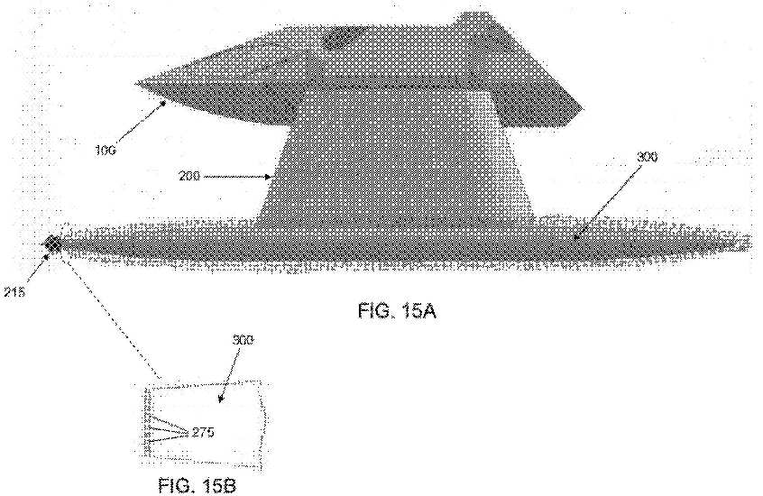
[0164] FIGS. 15A and 15B are
schematic views showing how a gaseous envelope may be provided
around the BTFs so as to reduce drag as the vessel moves
through the water;
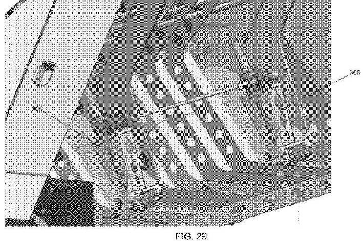
[0165] FIGS. 16-26 are schematic
views showing further details of spoilers used to steer the
novel attack craft and adjust its attitude;
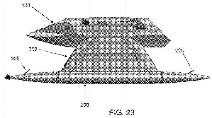
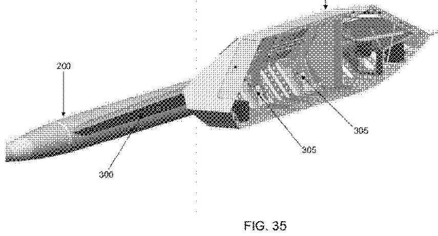
[0166] FIGS. 27-36 are schematic views showing how the
position of the struts and BTFs can be adjusted relative to
the command module;
[0167] FIG. 37 is a cross-sectional
view of a buoyant tubular foil having air channels therein and
having air trap fins on portions of its periphery, and further
shows preferred configurations of air trap fins;
[0168] FIG. 37A is similar to FIG.
37, but showing a substantially complete array of air trap
fins mounted on the tubular foil;
[0169] FIGS. 37B and 37C are side
elevational views of a buoyant tubular foil having air trap
fins thereon and extending onto a strut fixed to the tubular
foil;
[0170] FIG. 37D is a
cross-sectional view of a buoyant tubular foil having air
channels therein;
[0171] FIG. 38 is a schematic view
of a marine vessel having a propeller system comprising a
single propeller; and
[0172] FIG. 39 is a schematic view
of a single buoyant tubular foil in the form of a torpedo.
DETAILED DESCRIPTION OF THE
INVENTION
Overview
[0173] Looking first at FIGS. 1-6, there is shown a novel fleet
protection attack craft 5. The attack craft 5 generally
comprises a command module 100 for carrying a crew, weapons and
payload (including passengers), a pair of buoyant tubular foils
(BTFs) 200 for providing buoyancy, propulsion and steering, and
a pair of struts 300 for supporting command module 100 on BTFs
200.
[0174] As seen in FIGS. 4, 7 and 8, and as will hereinafter be
discussed in further detail, struts 300 can be disposed in a
variety of different positions vis-à-vis the command module 100,
so that the attack craft 5 can assume a number of different
configurations, depending on the desired mode of operation,
whereby to provide high speed, extreme stability, and stealth
capability.
[0175] Thus, for example, in standard seas, attack craft 5 may
be placed in the configuration shown in FIG. 4 (i.e., so that
the struts 300 are disposed approximately 45 degrees off the
horizon, and at approximately a right angle to one another) so
that command module 100 is safely out of the water and the
vessel has modest radar, infrared and visual signatures.
[0176] However, in high seas, while operating at high speed,
attack craft 5 can be placed in the configuration shown in FIG.
7 (i.e., so that the struts 300 are disposed substantially
perpendicular to the horizon, and substantially parallel to one
another) so that the command module 100 stands well out of the
water and is free from the affect of swells.
[0177] Furthermore, depending on sea conditions, the attack
craft 5 can be in a configuration somewhere between those shown
in FIGS. 4 and 7.
[0178] Attack craft 5 is also designed to operate in stealth
mode, by lowering its physical profile. In this case, the attack
craft 5 can be placed in the configuration shown in FIG. 8
(i.e., so that struts 300 are disposed almost parallel to the
horizon, and almost co-linear with one another) so that the
command module 100 is disposed just above, or actually in, the
water, reducing its radar, infrared and visual signatures. This
mode can be very useful when the attack craft 5 is being used
for reconnaissance purposes and/or to deliver small teams of
special forces behind enemy lines and/or to extract the same.
[0179] Thus, in one preferred form of the invention, the attack
craft 5 is normally operated in the configuration shown in FIG.
4, with the command module 100 completely out of the water, but
the command module being as low as possible so as to have a
reduced profile. However, in high seas and at high speed, the
attack craft 5 may be operated in the configuration shown in
FIG. 7, so that the command module 100 stands well clear of any
swells. And, when desired, the attack craft 5 can be operated in
the configuration shown in FIG. 8 so as to assume a stealth
mode.
[0180] Or, attack craft 5 can be operated in a selected
configuration between those shown in FIGS. 4, 7 and 8.
Prior Art Designs for Achieving High Speed and/or Extreme
Stability
[0181] There are currently two competing approaches for
achieving high speed and/or high stability in a water craft.
These are (i) the hydrofoil approach, which generally provides
high speed; and (ii) the Small Waterplane Area Twin Hull (SWATH)
approach, which generally provides high stability.
The Hydrofoil Approach
[0182] Hydrofoils have been in experimental use for many years,
and today are in active service around the world for a variety
of applications. Hydrofoils generally employ small airplane-like
wings ("lifting foils") which provide lift for the hull of the
vessel. The lifting foils are typically lowered into the water
while the vessel is underway. At higher speeds, the lifting
foils are capable of lifting the hull of the vessel completely
out of the water, thereby allowing the vessel to operate with
only its lifting foils (and their supporting struts) in the
water, whereby to minimize drag and increase vessel speed.
However, the lifting foils themselves provide no buoyancy and
therefore cannot support the vessel at slower speeds. Thus, the
vessel can only operate in hydrofoil mode when moving at
substantial speeds. In addition, due to the thin nature of the
hydrofoil's lifting foils, it is not possible to house the
vessel's engines within the lifting foils themselves-instead, it
is necessary to house the engines within the hull of the vessel
and to use transmission technologies (e.g., mechanical,
hydraulic and/or electrical means) to transfer power from the
vessel's engines down to its lifting foils, which carry the
propellers. However, these power transmission technologies all
involve substantial losses in power (thereby necessitating the
use of larger engines and/or resulting in lower speeds) and
significantly complicate the propulsion system of the vessel.
The SWATH Approach
[0183] SWATH vessels employ two or more torpedo-shaped
structures which are disposed underwater and attached to the
main body of the vessel with fixed vertical struts. The
torpedo-shaped structures provide buoyancy for the main body of
the vessel, which remains completely out of the water. In this
way, SWATH vessels resemble catamarans, except that the two
pontoon hulls of the catamaran are replaced by underwater
torpedo-shaped structures which reside immediately below the
hull at the ends of the vertical struts. The SWATH design
generally provides excellent stability because the underwater
torpedo-shaped structures are less affected by wave action than
a traditional wave-riding hull. However, the substantial skin
friction, and the inefficient hydromantic shape of the large
underwater torpedo-shaped structures, generally result in higher
power consumption. This higher power consumption in turn
necessitates the use of larger engines and/or results in reduced
vessel speed. However, the use of larger engines is itself
problematic, since the engines must then be housed in the hull
or, if the engines are to be housed in the underwater
torpedo-shaped structures, the underwater torpedo-shaped
structures must be enlarged. Housing the engines in the hull
introduces all of the power transmission problems discussed
above with respect to hydrofoils, inasmuch as the propellers are
mounted to the underwater torpedo-shaped structures. Conversely,
enlarging the underwater torpedo-shaped structures increases
skin friction problems, and inefficient hydromantic shape
problems, discussed above-which in turn necessitates the use of
even larger engines. For this reason, it has previously been
impossible to build a small, high-speed SWATH vessel. In
addition to the foregoing, the SWATH design typically requires a
high profile in order to ensure that the hull of the vessel
remains completely out of water, particularly in high seas. This
gives the SWATH vessel larger radar, infrared and visual
signatures, thereby making it easy to detect and target.
Novel Approach for Achieving High Speed and Extreme Stability
[0184] The present invention overcomes the problems associated
with the prior art through the provision and use of novel fleet
protection attack craft 5. Attack craft 5 supports a command
module 100 on a pair of buoyant tubular foils (BTFs) 200 via
movable struts 300. BTFs 200 normally provide all of the
buoyancy required for the craft, with command module 100
remaining completely out of the water. More particularly, BTFs
200 and struts 300 are often the only portions of the craft
which contact the water, and they provide low friction
hydromantic cross-sections so as to minimize water resistance.
Significantly, BTFs 200 house substantially all of the
propulsion, fuel and steering systems for the craft, thereby
providing the craft with an unusually low center of gravity and
permitting the volume of command module 100 to be dedicated to
crew, weapons and payload. Furthermore, struts 300 are movable
relative to command module 100, thereby permitting the craft to
assume a number of different configurations. This unique
approach results in a craft with unparalleled speed and
stability regardless of sea conditions, and with lower radar,
infrared and visual signatures, thereby making it difficult to
detect and target. Various aspects of the craft will now be
discussed in further detail.
Command Module 100
[0185] Referring to FIGS. 1-9, command module 100 generally
comprises a watertight enclosure 105 (FIG. 3) having a hull-like
bottom surface 110 (FIGS. 4, 5, 7 and 8). Command module 100
includes a cockpit 115 (FIGS. 2, 3, 6 and 8) for housing a pilot
and weapons officer, and a bay 120 (FIG. 9) for housing weapons
and payload (including passengers). Command module 100 further
includes a rear hatch 125 (FIGS. 5, 6 and 9) for permitting
entry and exit of crew, weapons and payload (including
passengers), and a top hatch 130 (FIGS. 2, 6 and 9) for
permitting various weapons systems to be raised out of the bay
120, fired, and then lowered back into the bay 120.
[0186] Command module 100 is armored to protect all occupants,
weaponry and payload. Windscreens 135 (FIGS. 7 and 9) are formed
of bullet-resistant materials.
[0187] Command module 100 comprises watertight bulkhead
enclosures which, combined with hull-like bottom surface 110,
allow waves to wash over the command module without effect when
the attack craft 5 is operating in its stealth mode (see below).
Automatic vent doors seal any open systems against water leakage
when attack craft 5 is in the stealth mode.
[0188] The outer structure of the command module 100 is
preferably based on so-called "stealth" principals in order to
minimize the radar signature of the craft. More particularly,
the outer surface of the command module 100 is designed to
deflect radar energy and return only a minimal amount of radar
energy to the radar transmitter. To this end, the exterior
surfaces of command module 100 are preferably highly angular,
with the angles being selected so as to reflect the radar energy
either downward towards the water or upward into the sky. In any
case, the exterior surfaces of the command module 100 minimize
the amount of radar energy reflected directly back to the
sender. Furthermore, the command module 100 preferably
incorporates a radar-absorbent paint which is capable of
absorbing or further reducing any incident radar energy.
[0189] Command module 100 is also configured to house all of the
control systems for piloting the attack craft, all of the
weapons control systems for operating the weapons carried by the
attack craft, an auxiliary generator for supplemental power
requirements (e.g., for navigation), a battery charger, an air
filtration system, a head, a sink, an air compressor, etc.
[0190] The weapons systems carried by attack craft 5 preferably
comprise (i) one 20 mm Vulcan Gatling gun, equipped with optic
and night vision; (ii) two 30 caliber Miniguns equipped with
optic and night vision; (iii) one or more 2.5 inch laser-guided
rockets; and (iv) 8 "mini" torpedoes. Preferably, the Gatling
gun, Miniguns and rockets are housed within bay 120 for elevated
deployment through the top hatch 130, and the "mini" torpedoes
are mounted to the exterior of the command module 100, e.g.,
such as is shown at 140.
Buoyant Tubular Foils (BTFs) 200
[0191] Referring next to FIGS. 10-15, a pair of the buoyant
tubular foils (BTFs) 200 provide buoyancy, propulsion and
steering for the attack craft 5. Each of the BTFs 200 generally
comprises a hollow tubular structure 205 which houses an engine
210 for powering a propeller system 215, a fuel tank 220 for
supplying fuel to engine 210, and steering elements (or
spoilers) 225 for steering the attack craft 5.
Hollow Tubular Structure 205
[0192] Hollow tubular structure 205 generally comprises a hollow
hull which provides buoyancy for the attack craft 5. Hollow
tubular structure 205 is configured to provide stability at low
speed operations while still providing low water friction and an
improved hydromantic profile to enable speeds of over eighty
knots. At high speeds, the configuration of the hollow tubular
structure 205 provides extraordinary stability for the vessel,
due to the flow of water over the elongated tubular structure
205.
[0193] More particularly, the low friction hydromantic
cross-section of hollow tubular structure 205 traverses water
with the lowest possible skin friction forces and the best
hydromantic shape obtainable, yet still houses the engine 210
and the fuel tank 220, and supports the propeller system 215 and
steering elements 225. It has been determined that best
performance is achieved where the hollow tubular structure 205
has a cross-section which is between about 1/10 and about 1/30
of the length of hollow tubular structure 205, and preferably
about 1/20 of the length of the hollow tubular structure. By way
of example, but not limitation, excellent performance can be
achieved when the hollow tubular structure 205 has a 3 foot
outer diameter and a 60 foot length.
[0194] As seen in FIGS. 12-15, the hollow tubular structure 205
comprises a plurality of disconnectable sections that permit
easy access to components disposed within the interior of the
hollow tubular structure 205, e.g., for maintenance and quick
replacement of power and sensor modules. By way of example, but
not limitation, the hollow tubular structure 205 can comprise a
center section 230 which is mounted to a strut 300, a forward
section 235 which is dismountable from the center section 230,
and a rear section 240 which is dismountable from the center
section 230. Preferably, interior components are equipped with
slides for easy entry into, and removal from, the hollow tubular
structure 205. By way of example, but not limitation, FIG. 14
shows how the engine 210 may be equipped with slides 245 for
supporting the engine 210 within the hollow tubular section 205,
and to facilitate insertion into, and removal from, the hollow
tubular structure 205.
[0195] The forward section 235 and the rear section 240 can
mount to the center section 230 in a variety of ways. By way of
example, but not limitation, the sections can be mechanically
held together (e.g., by hydraulics, power screw actions, etc.)
or they can twist lock together (e.g., in the manner of a
bayonet-type mount). A watertight seal is provided between the
sections so as to ensure hull integrity. The seal can be a
continuous circular shape to match the cross-section of the
hollow tubular structure 205, e.g., a resilient O-ring having a
round or flat cross-section. Alternatively, the O-ring can be an
inflatable seal (e.g., like the inner tube of a bicycle tire)
that can provide adjustable sealing forces by the injection of
an appropriate amount of fluid (e.g., gas or liquid).
Preferably, each O-ring seal has two sealing surfaces, i.e., the
face surface between adjacent sections and the face surface
against the skin of the hollow tubular structure 205.
[0196] The ability to quickly unlock the various sections of the
hollow tubular structure 205 permits the rapid servicing and/or
replacement of the various components contained within the
hollow tubular structure 205, e.g., engine 210, fuel tank 220,
etc.
Gas Turbine (Jet) Engine Propulsion
[0197] The engine 210 can be a conventional diesel engine,
internal combustion engine, rotary engine, electric motor, etc.
Preferably, however, the engine 210 comprises a gas turbine
(jet) engine, e.g., of the sort used in aircraft, and
particularly of the sort used in helicopters. A gas turbine
engine is preferred due to its high power, small size and low
weight. More particularly, a gas turbine engine typically has a
horsepower-to-weight ratio of about 2.5 horsepower (HP) per
pound. By comparison, a modern marine diesel engine typically
has a horsepower-to-weight ratio of about 0.5 HP per pound.
Inasmuch as there is generally a direct correlation between
vessel acceleration and weight, it is generally desirable to use
a high power, low weight engine in a high speed craft. Thus, a
gas turbine engine is the preferred propulsion unit for the
attack craft 5.
[0198] Significantly, a gas turbine engine is also ideal for use
in the attack craft 5 inasmuch as its size and configuration are
perfectly suited for disposition within the hollow tubular
structure 205. More particularly, gas turbine engines typically
have an elongated, somewhat cylindrical configuration which
easily fits within a hollow tubular structure. Significantly,
gas turbine engines generally have relatively modest
cross-sections, such that the gas turbine engines fit within a
relatively small diameter tube. By way of example, but not
limitation, the T53L13 gas turbine (jet) engine manufactured by
Lycoming Engines (a division of Avco Corporation, a wholly owned
subsidiary of Textron, Inc.) of Williamsport, Pa. has a diameter
which is ideally suited for disposition within the hollow
tubular structure 205 of the attack craft 5.
[0199] The use of a gas turbine engine in BTFs 200 also provides
significant additional advantages.
[0200] First, the use of a gas turbine engine in each BTF 200
easily allows for the use of a centerline drive shaft to
transfer power to the propeller system 215. This is an enormous
advantage when it comes to efficiently delivering large amounts
of power to the propeller system 215.
[0201] Second, a gas turbine engine provides a starter generator
that performs two functions, i.e., (i) to start the turbine
engine, and (ii) to generate DC power. More particularly, most
gas turbine engines provide 24 volts DC at 300 amps. This allows
the attack craft 5 to power all of its electrical systems from
the gas turbine engines, with the need for only a small
supplemental generator for charging batteries.
[0202] In addition, placing a gas turbine engine inside the
hollow tubular structure 205, which is underwater, also provides
superior cooling for the gas turbine engine since the radiated
engine heat is transferred to the surrounding water through the
skin of the hollow tubular structure 205.
[0203] Furthermore, gas turbine engines are generally designed
to be quickly and easily removed (e.g., by sliding) from an
aircraft fuselage. Similarly, the gas turbine engine can be
quickly and easily removed (e.g., by sliding) from the hollow
tubular structure 205.
[0204] The gas turbine engine usually has a high internal rpm
(greater than 19,000 rpm) with internal gear reductions.
Preferably, a gearbox 250 using planetary gears connects the
engine 210 to the propeller system 215. This approach provides a
gearbox which is smaller than the outside diameter of the gas
turbine engine.
Gas Turbine (Jet) Engine Intake And
Exhaust
[0205] The "Achilles heel" of a gas turbine engine is its need
to rapidly intake large quantities of fresh air and to rapidly
expel large quantities of exhaust air. As a result of this need
to rapidly move large quantities of air in and out of the gas
turbine engine, gas turbine engines have not heretofore been a
candidate for use in underwater structures (e.g., submarines and
the submerged portions of SWATH vessels) due to the inability to
adequately aspirate the jet engines.
[0206] A critical aspect of the attack craft 5 is the air intake
and exhaust systems which support the use of gas turbine engines
underwater. In this respect, it will be appreciated that the
design of the air intake and exhaust systems is complicated by
the fact that attack craft 5 is designed to change
configurations (e.g., as shown in FIGS. 4, 7 and 8) and the air
intake and exhaust systems must be able to accommodate these
configuration changes. More particularly, in attack craft 5, the
gas turbine engines are housed underwater in BTFs 200, the BTFs
200 are disposed at the ends of struts 300, and struts 300 are
movable relative to command module 100 (see FIGS. 4, 7 and 8).
Thus, the air intake and exhaust systems of the attack craft 5
must be capable of rapidly moving large quantities of air in and
out of the gas turbine engines, and through the struts 300,
while at the same time accommodating movement of the struts 300
relative to the command module 100.
[0207] To this end, the attack craft 5 comprises an air intake
and exhaust system for rapidly delivering large quantities of
fresh air to the gas turbine engine 210 and for rapidly
expelling large quantities of exhaust air from the gas turbine
engine 210. The air intake and exhaust system generally
comprises an engine intake duct 255 and an engine exhaust duct
260. The intake side of the engine intake duct 255 is disposed
in the command module 100 so that it can access cool air, which
increases the efficiency of the gas turbine engines 210.
Preferably, the intake side of the engine intake duct 255 is
funneled so as to generate ram air forces while the attack craft
5 is moving at speed, which further increases the efficiency of
the gas turbine engines 210. The outlet side of the engine
exhaust duct 260 is disposed in the command module 100 so as to
provide efficient exhaust venting with a minimal heat signature.
Engine intake duct 255 and engine exhaust duct 260 preferably
pass through a flexible coupling located at a junction of the
strut and the command module, in order to accommodate movement
of the strut vis-à-vis the command module. This flexible
coupling also accommodates other lines passing from the command
module 100 to the BTFs 200 via the struts 300, e.g., fuel
re-fill lines, electrical power lines, electrical control lines,
etc.
[0208] It should be appreciated that the flexible coupling is
configured so as to allow engine intake and engine exhaust to be
vectored and bent while still accommodating the large gas
volumes associated with the gas turbine engine. Furthermore, the
flexible coupling is designed to accommodate high exhaust
temperatures created by the gas turbine engine. The use of
heat-resistant flexible materials in the coupling is essential
to allow movement of the struts relative to the command module.
[0209] It should also be appreciated that moving large
quantities of air through a narrow strut (which is thinner than
BTF 200) entails using substantially the entire inner structure
of the strut as an air intake duct and an engine exhaust duct.
In one preferred form of the invention, the engine exhaust duct
260 is routed inside the air intake duct 255 so as to allow the
exhaust to be cooled by the intake air, whereby to provide a
lower thermal signature for the attack craft 5. In another
preferred form of the invention, the engine exhaust duct 260 is
not routed inside air intake duct 255-rather, in this form of
the invention, engine exhaust duct 260 is separate from the air
intake duct 255, and the exhaust in engine exhaust duct 260 is
separately cooled, e.g., with a water cooling jacket.
Furthermore, in this form of the invention, insulation may be
used to keep the cool air in the air intake duct 255 from being
heated by the hot exhaust in the engine exhaust duct 260 in
order to increase the efficiency of the gas turbine engines 210.
[0210] Preferably, the engine exhaust duct 260 includes
insulation to prevent heat of the gas turbine engine 210 from
overheating the outer skin of the strut 300.
[0211] In one form of the present invention, the engine exhaust
ducts 260 are double-walled, so as to allow a fluid to be
circulated around the inner hot duct, whereby to further cool
the engine exhaust and provide a lower thermal signature.
Attack Craft Propulsion Using
Battery Power
[0212] Preferably, the attack craft 5 also includes an electric
motor (not shown) and batteries (not shown) for selectively
driving the propeller system 215. More particularly, in certain
circumstances (e.g., reconnaissance operations and the delivery
and/or extraction of special forces) it may be desirable to
operate with reduced noise. In these circumstances, the electric
motor and batteries may be used in place of the gas turbine
(jet) engine discussed above.
Propeller System 215
[0213] Most vessels in use today utilize propellers which are
disposed at the stern of the vessel and push the vessel through
the water. This approach is generally satisfactory for most
vessels. However, stern-mounted, pushing propellers are
generally not satisfactory for those vessels which are trying to
achieve very high speeds, e.g., speeds in excess of 80 knots.
This is because propellers located at the stern of the vessel
engage water which has been agitated by the prior passage of the
vessel through the water. Since the efficiency of propellers is
highly affected by the state of the water the propellers move
through, stern-mounted, pushing propellers are generally
impractical for high speed craft.
[0214] Some high speed boats in use today (e.g., hydroplanes and
ocean racing boats) use stern-mounted, surface-penetrating,
forward-facing propellers that ride partially submerged in
agitated water with air mixed in. These piercing propellers are
designed with a heavy trailing edge and anti-cavitation cupping.
These piercing propellers withstand the extreme forces of high
horsepower and high rpm because the propeller is never fully
engaged in the water.
[0215] However, this type of propeller would not be effective
for the attack craft 5, since with BTF 200, the propeller system
215 must be fully submerged.
[0216] Significantly, the present invention utilizes a propeller
system 215 which comprises a pair of forward-facing, pulling,
counter-rotating propellers 265, 270 located at the bow end of
each BTF 200.
[0217] More particularly, a propeller system 215 is placed at
the bow of each BTF 200 so that the forward-facing, pulling
propellers can "bite" into virgin water, whereby to obtain
maximum efficiency. Furthermore, each propeller system 215
comprises two propellers, a leading propeller 265 and a trailing
propeller 270, operated in a timed, counter-rotating mode, so as
to provide reduced cavitation for the forward propeller. Leading
propeller 265 is the main propulsion element and does the
majority of the work of pulling of the vessel. Trailing
propeller 270 spins in the opposite direction from the leading
propeller and evacuates water from behind the leading propeller,
thereby permitting the leading propeller to work with maximum
efficiency. Thus, trailing propeller 270 moves water out from
behind leading propeller 265 so that the leading propeller can
pull more water in. This provides increased propeller
efficiency, which translates into higher speed and lower fuel
consumption.
[0218] Using the serially-mounted, counter-rotating propellers
265, 270 also permits smaller propeller diameters to be used.
This is because the surface areas of the two propellers combine
to provide an overall effective surface area which is equivalent
to the surface area of a single, larger diameter propeller.
However, it is difficult to rotate a large diameter propeller at
high speeds due to the forces involved. Thus, the use of
serially-mounted, counter-rotating propellers permits the
propellers to be rotated at higher rpms, thereby permitting
higher speeds to be achieved.
[0219] In addition to the foregoing, by using two
counter-rotating propellers, there is no side torque. More
particularly, side torque in propellers is the result of the
centrifugal forces created by the rotation of the propeller.
This side torque creates a tendency for the vessel to turn in
the direction of the rotation of the blade. Side torque is not
desired with attack craft 5, since it involves a loss of energy
and can create steering issues for the vessel.
[0220] The gearbox 250 connects the gas turbine engine 210 to
the propeller system 215. More particularly, the gearbox 250 is
configured to convert the single rotational motion of the output
shaft of the gas turbine engine 210 into the dual, co-axial,
counter-rotational motions needed to drive the counter-rotating
propellers, 265, 270.
Super-Cavitation
[0221] By placing the counter-rotating propellers 265, 270 on
the forward end of BTFs 200, the propellers are able to pull the
vessel through clean, undisturbed, virgin water, thereby
ensuring optimal propeller performance. In addition, by placing
the two serially-mounted, counter-rotating propellers on the
fount end of BTFs 200, attack craft 5 is able to generate a
highly gaseous environment, comprising a jet stream of dense
collapsing bubbles that encapsulate BTFs 200 and significantly
reduce vessel drag. More particularly, the actions of the
propellers 265, 270, working together, pull water through the
leading propeller 265 and allow the trailing propeller 270 to
heavily cavitate the rapidly moving water and create a heavy
stream of gaseous bubbles which surround the outer surfaces of
BTFs 200. This gaseous envelope reduces hull drag and greatly
increases the speed of the vessel, since the BTFs are
essentially "flying through bubbles". See FIG. 15A. In this
respect it should be appreciated that the kinetic coefficient of
friction with air is approximately 1/800th the kinetic
coefficient of friction of water. Furthermore, the faster the
vessel goes, the greater the reduction in hull friction,
inasmuch as (i) a greater quantity of gaseous bubbles are
created by the serially-mounted, counter-rotating propellers,
and (ii) the bubbles do not have time to collapse before BTFs
200 have passed completely through them.
[0222] Attack craft 5 can also include additional means for
producing an encompassing gaseous envelope. More particularly, a
plurality of small holes 275 (FIG. 15B) are preferably located
immediately behind trailing propeller 270 and disposed in a
circler fashion about the periphery of the BTF structure. The
holes 275 are in communication with ductwork leading to the
outside air, allowing the trailing propeller to create a siphon
effect, drawing air down for release just aft of the trailing
propeller, whereby to create an even more dense gaseous envelope
for reducing BTF friction. Alternatively, a pressurized gas
source connected to the small holes 275 can also be used to
release gas immediately aft of the trailing propeller, whereby
to create the desired gaseous envelope for reducing BTF
friction.
[0223] In yet another form of the invention, a supply of
friction-reducing fluid (e.g., detergent) can be connected to
the aforementioned small holes 275, whereby to create the
desired friction-reducing envelope about BTFs 200.
Rudderless System
[0224] Conventional rudders are continuously deployed in the
water, so that they create friction and drag not only when being
manipulated so as to change the direction of the vessel, but
also under normal operating conditions. This friction and drag
has a substantial detrimental effect on the speed of the vessel.
[0225] In contrast, and looking now at FIGS. 16-26, attack craft
5 provides forward and aft steering elements (or spoilers) 225
that are projectable from, and retractable into, the outer skin
of hollow tubular structure 205. In this respect it should be
appreciated that each of the spoilers 225 can be projected an
adjustable amount outboard from hollow tubular structure 205.
Furthermore, command module 100 can be provided with various
control systems which permit each of the spoilers 225 to be
operated in a coordinated fashion or, if desired, independently
from one another.
[0226] In one preferred form of the invention, sixteen spoilers
225 are provided: four spoilers 225 at the front of each BTF 200
and four spoilers 225 at the rear of each BTF 200, with spoilers
225 being disposed at the "12 o'clock", "3 o'clock", "6
o'clock", and "9 o'clock" positions. This arrangement allows
spoilers 225 to apply left, right, up and/or down forces (or any
combination thereof) to the front and/or rear of each of the
BTFs 200 while attack craft 5 is underway.
[0227] Spoilers 225 provide numerous significant advantages over
conventional rudders.
[0228] For one thing, spoilers 225 provide substantially no drag
when the vessel is underway and no directional changes are
needed-this is because the spoilers then reside flush with the
outer skins of the hollow tubular structures 205. Spoilers 225
impose drag on the vessel only when they are extended outwardly
from the skins of the hollow tubular structures 205, whereby to
provide the forces necessary to maneuver the vessel-and they are
thereafter returned to their inboard (i.e., flush, and no-drag)
positions as soon as the maneuver is completed and the vessel
returns to standard forward motion.
[0229] Additionally, and significantly, the provision of the
spoilers 225 on the fore and aft portions of hollow tubular
structures 205 permits the application of more dramatic turning
forces. More particularly, by setting a fore spoiler to turn in
one direction and a corresponding aft spoiler to turn in the
opposite direction, significant turning forces can be quickly
and easily applied to the vessel using spoilers of relatively
modest size. Thus, course corrections can be effected quickly,
making the vessel extremely agile, while permitting the turning
friction of the spoilers to be applied only for short durations.
[0230] Spoilers 225 can be used for turning left or right (see
FIGS. 16-19), for adjusting the trim (i.e., the up/down
attitude) of the vessel (see FIGS. 20-23), and/or to enhance
deceleration of the vessel (see FIGS. 24-26).
[0231] Spoilers 225 can be flush plates that protrude from the
outer skins of the hollow tubular structures 205 and cause
friction when needed to change direction. Alternatively, the
spoilers 225 can be made of an elastomeric material that can be
inflated with air, fluids, etc. and which protrude from the
outer skins of the hollow tubular structures 205.
Fuel Tanks 220
[0232] Fuel tanks 220 are housed inside BTFs 200, preferably in
the center section 230. Fuel tanks 220 preferably comprise
double-walled tanks made of a flexible bladder material (e.g., a
flexible bladder disposed inside another flexible bladder). This
arrangement allows for a fluid (e.g., seawater) to be pumped
into the outer bladder in order to compensate for the
consumption of fuel from within the inside bladder, thereby
ensuring that the buoyancy of the attack craft remains constant.
Center of Gravity
[0233] The center of gravity for the attack craft 5 is intended
to be as low as possible, in order to maximize vessel stability.
This is achieved by positioning heavy components such as the
engines 210 and the fuel tanks 220 within the BTFs, thereby
lowering the vessel's center of gravity so as to be as close as
possible to the midline of the BTFs. In this respect, it will be
appreciated that turbine engines 210 and fuel tanks 220
constitute approximately [2/3] of the total vessel weight and,
due to the construction of the attack craft 5, this weight is
disposed entirely below the waterline. This leads to enhanced
vessel stability.
Connecting Struts 300
[0234] As noted above, the connecting struts 300 attach BTFs 200
to the command module 100. As also noted above, the struts 300
are designed to be fixed to the BTFs 200 and pivot on the
command module 100 to allow attack craft 5 to assume different
configurations (FIGS. 4, 7 and 8), whereby to permit the command
module 100 to sit different distances from the water. As seen in
FIGS. 27-36, the struts 300 comprise hydraulic or electric jack
screws 305 connected to load arms located within struts 300,
whereby to move struts 300 relative to command module 100. In
this respect, it will be appreciated that FIGS. 27-29 show
struts 300 in a position corresponding to the attack craft
configuration shown in FIG. 4. FIGS. 30-32 show the struts 300
in a position corresponding to the attack craft configuration
shown in FIG. 7, and FIGS. 33-36 show struts 300 in a position
corresponding to the attack craft configuration shown in FIG. 8.
[0235] Since struts 300 extend into the water, it is important
to keep the struts as thin as possible so as to minimize drag.
[0236] It should also be appreciated that the structural
integrity of the struts 300 relies primarily on the strength of
the load arms located within the struts acting in conjunction
with the outer skin of the struts, while using minimal internal
frames. This is important, since the struts 300 need to have
large areas of uninterrupted volume in order to permit engine
intake to pass uninterrupted through the interior of the struts.
Fly-by-Wire Controls
[0237] In one preferred form of the invention, sensors are
located on the hull-like bottom surface 110 of the command
module 100 and continuously measure the distance of the command
module from the water surface. A computer automatically adjusts
the disposition of the struts 300 so as to maintain the command
module a desired distance above the water surface. In this
respect, it will be appreciated that, particularly when the
attack craft 5 is operating at high speeds (e.g., 80 knots) in
open water, it is important to keep the command module 100 from
coming into contact with the surface of the water (and
particularly important to keep the command module 100 from
coming into contact with the irregular sea swells commonly found
in the open sea).
[0238] Thus, for example, in standard seas, the attack craft 5
can be placed in the configuration shown in FIG. 4, so that the
command module 100 is safely out of the water and the vessel has
modest radar, infrared and visual signatures.
[0239] However, in high seas, while operating at high speed, the
attack craft 5 can be placed in the configuration shown in FIG.
7 so that the command module 100 stands well out of the water
and is free from the affect of swells.
[0240] Furthermore, depending on sea conditions, the attack
craft 5 could be in a configuration somewhere between those
shown in FIGS. 4 and 7.
[0241] Attack craft 5 is also designed to operate in stealth
mode, by lowering its physical profile. In this case, the attack
craft 5 can be placed in the configuration shown in FIG. 8, so
that the command module 100 sits just above, or actually in, the
water, reducing its radar, infrared and visual signatures. This
mode can be very useful when the attack craft 5 is being used
for reconnaissance purposes and/or to deliver small teams of
special forces behind enemy lines and/or to extract the same.
[0242] Thus, in one preferred form of the invention, the attack
craft 5 is normally operated in the configuration shown in FIG.
4, with the command module 100 completely out of the water, but
the command module being as low as possible so as to have a
reduced profile. However, in high seas and at high speed, the
attack craft 5 may be operated in the configuration shown in
FIG. 7, so that the command module 100 stands well clear of any
swells. And, when desired, the attack craft 5 can be operated in
the configuration shown in FIG. 8 so as to assume a stealth
mode.
[0243] Or, the attack craft 5 can be operated in a configuration
somewhere between those shown in FIGS. 4, 7 and 8.
[0244] Preferably, speed sensors feed speed data to a main
computer, which adjusts the sensitivity of the steering controls
so that, while travelling at low speeds, the controls are more
reactive and when travelling at high speeds, the controls are
less reactive. In other words, the main computer preferably
adjusts the sensitivity of the steering controls so that (i)
large movements of the steering controls (e.g., a joystick) are
required at high speeds to make modest changes in the
disposition of the spoilers 225, and (ii) small movements of the
steering controls are required at slow speeds to make
significant changes in the disposition of the spoilers 225. This
construction eliminates the possibility that a modest movement
of the controls at high speed will result in a catastrophic
change in the direction or attitude of the craft.
Extendable BTF Boom
[0245] If desired, BTFs 200 can be provided with an extendible
boom. This boom is deployable from the after end of the BTF, and
is preferably flexible. The extendible boom can serve two
purposes.
[0246] First, the extendible boom can have controllable surface
protrusions along its length that can be enlarged or contracted
so as to allow drag to be applied to the boom, thus further
stabilizing the BTF in a manner similar to the tail of a kite.
The protrusions cause drag that stabilizes the vessel in both
the horizontal and vertical planes. The protrusions can be
controlled by elastic bladders which are inflated so as to
increase size (and hence drag) as desired, or a mechanical
device located at the end of the boom that provides mechanical
drag resistance, thereby increasing stability.
[0247] Second, the extendible boom can also house sonar,
listening devices, magnetometers, gravity interruption sensors,
etc. that can be used for the identification of submerged
objects. By mounting these devices on the end of an extendible
boom, the devices can be isolated from the remainder of attack
craft 5, so as to minimize interference with device function.
Super-Cavitating Air Channels: "Air
Trap Fins"
[0248] As described above, the present invention comprises a
high speed SWATH boat with pontoon-type underwater hull friction
reduction. Creating an air skirt around the hull of the buoyant
tubular foil (i.e., by propeller-generated supercavitation and
by injecting air through the hull and into the flow of water)
displaces water from around the hull, allowing air to come into
contact with the hull. Water has 800 to 1000 times more friction
than air, so the air skirt dramatically reduces friction as the
hull moves.
[0249] It is advantageous to keep the air bubbles traveling
horizontally along the hull as much as possible, so as to
decrease surface friction. Ideally, air needs to be maintained
about the hull so as to act like a cushion and friction
reduction means. At 50 knots, a 60 foot long structure passes
through the bubble region in one second, so it is important to
keep the air against the hull-even a 1/10 second increase in
bubble life results in substantial friction reduction for the
buoyant tubular foil. The following are various ways to do this:
[0250] 1. The hull is provided with many air outlet holes 310
located horizontally along the tubular foil 200, providing a
plurality of horizontal air outlet channels.
[0251] 2. The hull is provided with long horizontal air trap
fins 315 that allow air to be channeled along the length of the
hull and not allow all the air to immediately escape outwardly
and off the hull.
[0252] 3. The air trap fins 315 may be contoured (FIG. 37) so as
to force the air bubbles to follow a tortuous path to escape
from the hull.
[0253] 4. The air trap fins 315 may be disposed in a spiral
around the hull in a helical manner, e.g., like a screw (FIG.
37), so as to allow air to be trapped and constrained against
the hull as the air bubbles defuse along the channel.
[0254] 5. The air trap fins 315 may be of a scallop-type design
(FIG. 37), providing air channels adjacent the hull of the
buoyant tubular foil.
[0255] 6. The air trap fins 315 provide a water flow boundary
around the circumference of the underwater hull (FIGS. 37B and
37C), providing a decrease in water density around the boundary
water layer, from dense water to an air and water mixture. The
height of the mechanical air trap fins 315 determines the water
density boundary layer. The height of the fins 315 can be
proportionally adjusted depending on the length of the hull.
[0256] 7. The air trap fins 315 run for a portion or an entirety
of the length of the hull and may be radially distributed on all
surfaces (FIGS. 37B and 37C).
[0257] 8. The air trap fins 315 may be radially distributed,
except for the [1/4] to [1/2] bottom section of the underside of
the hull (FIGS. 37 and 37D), in order to allow the bottom of the
hull to ride on dense water and the remaining hull surfaces to
be in an air/water bubbles stream. This provides better
stability for the craft, due to the lack of compressibility of
dense water supporting the craft.
Single Propeller Cavitation
[0258] In an alternative embodiment shown in FIG. 38, the marine
vessel propeller system comprises a single propeller 530 placed
at the bow of a buoyant tubular foil 500. The propeller 530 is
sized and configured such that in operation the propeller
creates and dispenses rearwardly a stream of supercavitated
water which envelopes the marine vessel, which preferably is
provided with air trap fins, as previously described, and
operative to prevent immediate escape of the supercavitated
water from the foil 500. Again, steering may be provided by
spoilers as previously disclosed herein or, alternatively,
rudders as shown in FIG. 38.
Submarine or Torpedo Embodiment
[0259] In the foregoing disclosure, there is disclosed a novel
fleet protection attack craft 5 which generally comprises a
command module 100 for carrying crew, weapons and payload
(including passengers), a pair of buoyant tubular foils (BTFs)
200 for providing buoyancy, propulsion and steering, and a pair
of struts 300 for supporting command module 100 on BTFs 200.
[0260] It is further within the scope of the invention to
provide a novel submersible water craft, such as a submarine
and/or a torpedo and/or an unmanned drone, which utilizes a
single buoyant tubular foil, generally of the sort disclosed
above, as the body of the submersible water craft (e.g.,
submarine, torpedo, unmanned drone, etc.).
[0261] In one form of the invention, and referring to FIG. 39, a
single buoyant tubular foil, such as a body 500 of a torpedo,
may be provided with a warhead 510 (e.g., detonator and high
explosives) and provides for buoyancy (including negative
buoyancy where desired), propulsion and steering 515, as is
known in the art. More particularly, in this form of the
invention, buoyancy is preferably provided by ballast tanks 520
contained within the body 500 of the torpedo. Propulsion is
provided by at least one front-pulling propeller 530 of the sort
disclosed above, and an electric motor contained within the body
500 of the torpedo, with the front-pulling propeller or
propellers 530 providing an air skirt (supercavitation) around
the body 500 of the torpedo during movement of the torpedo
through water, in the manner previously disclosed. Again,
steering may be provided by spoilers as previously disclosed
herein or, alternatively, rudders as shown in FIG. 39.
Front Pulling Propeller Mechanism
[0262] It should be appreciated that with the preferred form of
the present invention, a front pulling propeller mechanism is
used to both (i) pull the buoyant tubular foil (BTF) though the
water, and (ii) generate the friction-reducing air curtain which
engulfs the trailing BTF. Thus, the same element (i.e., the
front pulling propeller mechanism) is used to simultaneously
provide both propulsion and the supercavitating
friction-reducing air curtain. As noted above, each of these
aspects provides significant improvements in propulsion
efficiencies, with (i) the front pulling propeller mechanism
biting into virgin water, which enhances the propulsion action
of the propeller mechanism, and (ii) the front pulling propeller
mechanism providing the supercavitating friction-reducing air
curtain which reduces hull friction as the BTF moves through the
water. Uniquely, the front pulling propeller mechanism is used
to simultaneously provide both of these functions.
[0263] Significantly, the same approach is used regardless of
whether the BTF is part of a SWATH surface vessel, or the BTF is
the hull of a submarine or other submersible vessel, or the BTF
is the fuselage of another form of submersible vehicle such as a
torpedo or unmanned drone. In other words, with the preferred
form of the present invention, the front pulling propeller
mechanism simultaneously provides its dual function (i.e.,
propulsion and the supercavitating friction reducing air
curtain) for the elongated hull structure (i.e., the BTF) which
trails the front pulling propeller mechanism. In this way, the
elongated hull structure is moved through the water with great
efficiency and hence significantly increased speed.
[0264] It will be appreciated that it is important that the
front pulling propeller mechanism be configured (e.g., blade
shape, blade size, number of blades employed, counterrotation of
the blades if more than one blade is provided, etc.) and
operated (e.g., blade rotation speed, etc.) for both efficient
propulsion and efficient air curtain generation. In this latter
respect, it will be appreciated that the propeller mechanism
should generate an air curtain of sufficient size and volume to
engulf all (or substantially all) of the perimeter of the
trailing hull structure (i.e., the BTF). In this respect it will
be appreciated that not all front pulling propeller mechanisms
will generate the supercavitating friction-reducing air curtain
desired in the present invention. By way of example but not
limitation, a propeller rotating relatively slowly will generate
minimal supercavitation function (which may be a desired design
feature, such as on a ballistic missile submarine which may give
a priority to noise reduction). By way of further example but
not limitation, a relatively small propeller may throw off a
bubble stream, but the bubble stream may not be large enough to
engulf the perimeter of the trailing hull structure and provide
the desired air curtain about the outer surface of the trailing
hull structure. Thus it will be appreciated that attention must
be paid to the configuration of the front pulling propeller
mechanism (e.g., blade shape, blade size, number of blades
employed, counterrotation of the blades if more than one blade
is provided, etc.) and to the operation of the front pulling
propeller mechanism (e.g., blade rotation speed, etc.) in order
to provide the desired supercavitating friction-reducing air
curtain for the trailing hull structure. Appropriate design and
operational parameters will be apparent to those skilled in the
art in view of the present disclosure.
[0265] In one preferred form of the invention, the front pulling
propeller mechanism comprises a pair of counterrotating
propellers to efficiently provide both propulsion and the
supercavitating friction-reducing air curtain, with the
propellers having a diameter which is approximately X percent of
the diameter of the trailing BTF, and a rotation speed of
approximately Y revolutions per minute (rpm).
Non-Military and Civilian
Applications
[0266] In the foregoing description, the attack craft 5 is
described in the context of its use for military applications.
However, it should be appreciated that the craft 5 may also be
used for other, non-military applications, such as security
applications (e.g., police, immigration and drug enforcement
purposes), public safety applications (e.g., sea rescues),
high-speed servicing and re-supply applications (e.g., for
servicing oil drilling platforms), high-speed water taxi
applications, private pleasure craft applications, etc.
Modifications of the Preferred
Embodiments
[0267] It should be understood that many additional changes in
the details, materials, steps and arrangements of parts, which
have been herein described and illustrated in order to explain
the nature of the present invention, may be made by those
skilled in the art while still remaining within the principles
and scope of the invention.