Alexandr
A. KARASEV, et al.
SCENAR [ SKENAR ]
Self-Controlled Energo-Neuro-Adaptive Regulation
SCENAR [ SKENAR ]
Self-Controlled Energo-Neuro-Adaptive Regulation
http://www.scenar.info/
Scenar
Information

The S.C.E.N.A.R., Self-Controlled Energo Neuro Adaptive Regulation, was developed for the Russian space program to overcome the unique problems of space travel. Pharmaceuticals were impractical due to the specificity of each drug, leading to a need to store a large variety and quantity of drugs, and also due to the introduction of toxins into the water recycling system, such that one treatment may well treat the whole crew.
A Russian team of doctors and scientists, based at Sochi University and led by Alexander Karasev in the late 1970s, developed a method of treatment that was energy efficient, multi-applicable, portable and also non-invasive. They were the first people to achieve repeatable therapeutic treatment using electrical signals to stimulate the immune system. Head scientist Professor Revenko claimed that there were very few illnesses SCENAR could not treat and often cure. Tests conducted in Russia have since shown the Scenar is proves effective in 80% of cases.
The S.C.E.N.A.R. was immediately dubbed the ‘Star Trek’ Device by the press because of its origins and its similarity to the ‘all-curing’ medical scanner used in the series, Star Trek.
How it works
The scenar uses biofeedback -- by stimulating the nervous system, it is able to teach the body to heal itself. The device sends out a series of signals through the skin and measures the response. Each signal is only sent out when a change, in response to the previous signal, is recorded in the electrical properties of the skin. Visible responses include reddening of the skin, numbness, stickiness (the device will have the feeling of being magnetically dragged), a change in the numerical readout and an increase in the electronic clattering of the device.
The C-fibres, which comprise 85% of all nerves in the body, react most readily to the electro-stimulation and are responsible for the production of neuropeptides and other regulatory peptides.
The body can get accustomed to a stable pathological state, which may have been caused by injury, disease or toxicity. The scenar catalyses the process to produce regulatory peptides by stimulation of C-fibres for the body to use where necessary. It is these neuropeptides that in turn reestablish the body’s natural physiological state and are responsible for the healing process. As these peptides last up to several hours, the healing process will continue long after the treatment is over. The large quantity of neuropeptides and C-fibres in the Central Nervous System can also result in the treatment on one area aiding with other chemical imbalances, correcting sleeplessness, appetite and behavioral problems.
In Russia, there are over 50,000 cases of the device’s use and some 600 practitioners currently use the device as their principal treatment instrument. A vast wealth of information is available from research papers, clinical reports and training manuals. The device is used on most types of disease or injury: circulatory, sensory, respiratory, neurological, genito-urinary, musculo-skeletal, gastro-intestinal, endocrine, immune and psychological disorders.
The scenar is also credited with vastly reducing recovery times. Russian athletes have been known not only to compete after serious injuries, but even to break world-records. In accident and emergency wards, its ability to aid recovery is used to help victims of cardiac arrest, massive trauma and coma. It has recently been discovered to also aid in improving learning ability, memory, sexual function and improved physical health. Finally trials in Russia have also realised scenar’s usage for pain relief. Both cancer and fracture patients have found more pain relief from the release of natural opoids after scenar treatment than from administered opiates.
Treatment
The Scenar weighs approximately 300 grams, is 200mm in length, with an electrical contact at one end and runs off a 9V battery. This is run over the spine and abdomen or the infected area, recording the resistive response to its signals and using its sophisticated software to return a fresh signal. A gentle tingling/stroking sensation will be felt. The practitioner is looking for anomalies on the skin surface, which may be highlighted by redness, numbness, stickiness or a change in numerical display or sound. Although these areas may not seem to directly relate to the obvious symptom, by treating these ‘asymmetries’, (as the Russians call them), the healing process will commence.
Patients having Scenar treatment need to take responsibility for their health and are advised to participate actively in the treatment and recovery process. The chemical compounds, released by the nerves, affect not only the problem areas, but also circulate in the blood treating other areas of the body. This goes some way to explaining how old and often forgotten problems are brought to the surface for treatment.
The Russians state that a chronic problem that the patient has may take up to 6 weeks treatment, with long-lasting effectiveness. Acute problems may just take one or two treatments. They say that the Scenar proves effective in 80% of all cases, of which full recovery occurs in 2/3rds of them and significant healing in the remainder.
What conditions can Scenar treat?
In the UK, the devices are licensed by the British Standards Institute for pain relief only. However, because of the nature of the device, viz., stimulating the nervous system, the Russian experience is that Scenar affects all the body systems.
The Russian experience suggests that it can be effective for a very broad range of diseases, including diseases of the digestive, cardio-vascular, respiratory, musculo-skeletal, urinary, reproductive and nervous systems.
It is also useful for managing ENT diseases, eye diseases, skin conditions and dental problems. It has also been found beneficial in burns, fractures, insect bites, allergic reactions, diseases of the blood and disorders involving immune mechanisms; endocrine, nutritional and metabolic disorders; stress and mental depression, etc.
It is known to give real relief from many types of pain
How often will I need a treatment?
In order to create a continuous flow of circulating regulative peptides Scenar action must be given quite often. For any fresh injury or any acute inflammatory process treatment needs to be intensive, ideally once or even twice daily. For chronic conditions, treatments are ideally given three or four times a week initially. As things improve the frequency can be reduced.
A course of treatments will vary from individual to individual, and takes into account such factors as the stage of the pathological process, the person's age, state of health, and so on.
Is it safe?
As the Scenar impulse is similar to endogenous nerve impulses, it is non-damaging and safe. Only people with cardiac pacemakers are not allowed to have Scenar treatment.
Children and pregnant women can be treated, and even animals enjoy it!
What about my conventional treatment?
If you are receiving treatment from your doctor it makes sense to inform him about Scenar therapy. Treatment with Scenar may enable you to reduce or even stop taking some medication, and this can be done under the supervision of your doctor.
What else do I need to know?
During the treatment of chronic conditions, occasionally a healing crisis may occur (experienced as a complete lack of energy and malaise). This arises if the body is getting rid of toxic energy too rapidly. There are techniques that can be used with the Scenar to manage this.
For best results it is advisable not to bathe or shower for two hours before and after treatment. It may be necessary to shave an area of skin to ensure good communication between the device and the nervous system.
Patients generally experience an increase in energy, more refreshing sleep and an improved sense of wellbeing.
How does it differ from other therapies?
There are several ways in which it differs from other electrical therapies.
Unlike TENS machines, each impulse is different from the previous one so the body is unable to adapt to the signal.
The Scenar impulse is high amplitude so it stimulates C-fibres, which make up about 85% of the nerves in the body. This explains the quick effectiveness of Scenar therapy on the whole body.
WEBSITES
http://www.scenar.info/
http://www.scenar-revenko.ru
http://www.alternative-doctor.com/specials/scenar.htm
STAR
TREK MEDICINE IS HERE! NOW!!
Can a simple hand-held device work miracle cures? If it's the Russian SCENAR, you bet! (sometimes spelled SKENAR)
One of the most brilliant healing machines I discovered in my search for future trends while writing my book VIRTUAL MEDICINE is the Russian SCENAR device (self-controlled energo-neuro-adaptive-regulation.
Actually, it's a whole family of machines and I predicted they will completely change the face of medicine in the next 20 years. They are fast, portable, cheap and effective against almost any condition, from treat sports injuries, strokes, angina, acute infections, back pains and irritable bowel disease (as well as pre-menstrual tension and post-surgical complications) and even defibrillating hearts!
BACKGROUND
The origin of the machine is surrounded in secrecy from the Russian military. But it clearly springs from research into the electro-magnetic field effects of the body's biological energy. Eventually, a team of scientists and doctors was assembled to study possible medical applications of the technology. The SCENAR researchers subsequently used it to study an Eastern therapy known as zonal contact massage. The intention had been to develop some way of altering the pressure of the massage, according to skin response (in VIRTUAL MEDICINE chapter 3, I described how the dielectric potential of collagen tissue is stimulated by pressure).
Equipment was developed to monitor magnetic effects taking place in the skin and use these to modulate changes in pressure of the massage. The establishment of a biofeedback mechanism led to the creation of a device whose output would depend on skin energetic response.
The aim is to stimulate the body's own endogenous energies to effect the cure, creating a cascade of endogenous neuropeptides. This allows the body its own choice of healing ingredients; a sort of on-board pharmacy. Through biofeedback an interaction is formed between the tissues and the instrument, each new signal evolves as a new output. No two consecutive signals from the device are the same. This allows the treatment to be truly dynamic, adjusting for changes in the body through time and in different physiological states.
The term SCENAR was born. It is yet another brilliant marriage of Western electronic technology and Eastern energetic healing skills (which is what VIRTUAL MEDICINE is all about).
SPACE RACE
When the Soviet Union decided to send cosmonauts into orbit for prolonged periods, it was clear that they needed to have a means of treating any illnesses that could befall them. Unlike the American system, there were no convenient re-usable shuttles to bring back an ailing cosmonaut back to Earth, should the need have arisen. The possibility of incapacitating disease was a major worry.
The pharmaceutical approach was not tenable, bearing in mind the rigorous weight and space limitations and the fact that drug-oriented medicine is based on the principle of one substance for each (potential) condition. Even a very modest medicine range would be weighty. Also, in an environment where recycling of water is such an essential feature, any drug entering the water circulation system would remain, passing through the cosmonaut many times.
This was at a time when the Russian space programme was being watched by the rest of the world and maintaining national prestige was of paramount concern to the Soviet government. It was essential to come up with something radically new. It had to be light, easy to use and, of course, really effective.
Bioenergetic technology was the only extant medical paradigm capable of delivering these stringent requirements. The SCENAR came to the fore.
Ironically, no SCENAR device has been used in space to date. There were delays caused by the authorities insisting on a waterproofing process. Before this matter was resolved, funds were suddenly stopped at the time of perestroika; the so-called ‘space race' was called off and the team disbanded. The USA began working on combined space projects with the Russians and they introduced the capability of evacuating sick cosmonauts on the shuttle, which meant there was no further need of on-board therapy.
However, four of the original team felt they had designed a very worthwhile system, capable of changing the face of medicine, and decided to take it onto the open market. So far, around 600 doctors in Russia are using it as their principal treatment modality and it is now available to select and trained practitioners in the West. VIRTUAL MEDICINE has crossed-over into the mainstream!
The promise of a small hand-held device that is capable of curing most illness, such as was portrayed in the cult 1970s TV series "STAR TREK", has become a reality.
BOFFINS
The original inventor of the Scenar was A.A.Karasev an electronics engineer back in 1973 who made one for himself after some of his family members died and the conventional medicine of the day could not help.
Karasev later worked for the Russian Cosmonaut programme and showed his invention to his superiors who were very interested, so much so that a team was set up with funding to develop the idea further.
Manufacturing was (and still is for some models) carried out by the Priboy company which supplies military hardware.
The device was never actually used in space as they were unable to come up with a watertight model which was what had been specified.
The end of the communist era led to a cessation of funding but some of the members of the team decided to continue and formed the OKB Ritm company in 1983. Names you repeatedly come across are A.N.Revenko, Y.Grinberg, and Y.Gorfinkel as well as Karasev. They managed to get approval in 1986 from the Russian Ministry of Health for the device to be used in health clinics.
The OKB Ritm company still produces several models using names such as Scenar 97, Scenar NT, Scenar 2003, Autoscenar and Kosmed. (http://www.scenar.com.ru/index_eng.html) They have a branch office in the Netherlands. (http://www.ritmedic.com/home.html)
Karasev decided to go his own way in 1990 and set up the LET Medical company which produces a range of models under the Scenar and Cosmodic brands. (http://www.scenar.ru/en/)
The Rema company in Belorussia started producing Prologue and Enart models in 1993. (http://rema.by/) Check out their English powerpoint presentation where it says 'english version' (http://rema.by/?module=about)
CCC Invet is a reseller of several of the above companies products and has an English website. (http://www.invet.net/32/e/about_e.shtml)
Another company RTS ART was set up in 1995 and now trades as Denas MS producing the Denas and DiaDens models. (http://www.denascorp.ru/) They have many resellers some with English websites such as Diadens.com. (http://www.diadens.com/)
The Pervade Wave company in Hong Kong has a regional (Asia) licence to produce the Space Healer model. These are sold in HK (http://www.naturalhealing.com.hk/spacehealer.php) and in Australia (http://www.enlightenedtherapies.com/index.htm)
There is also supposed to be a US made model the Inter X 5000 from NRG (Neuro Research Group) but it is taking a very long time to come to fruition..
It seems that Ritm was originally happy to licence the Scenar idea to other companies, but then when they started to make their own variants disputes arose as to who could use the brand name Scenar and whose model was better etc. Hence there is quite a lot of mudslinging and you sometimes have to read between the lines.
Most of the companies originally targeted the health care market with expensive products although there are now some cheaper home-use models with reduced features. They also tended to sell training courses to their customers and provided little written documentation.
The exception seems to be the Denas company which decided to go down the network marketing route with large numbers of resellers and reasonable prices. They have four current models including a Euro Denas one with CE certification and an English version of their printed 240 page Denas Therapy Manual and its accompanying 2 hour video, although the English translation could be much improved. Their latest model the Diadens-DT even includes two electro acupuncture modes.
You can download a good 172 page English manual from Transformation Technologies website. (http://www.braintuner.com/skenar.htm). It is not stated where this manual came from but the preface is signed Sergey Solomko and he is the owner of the Invet company.
I also discovered that there is a wealth of Scenar related information on the internet but unsurprisingly mostly in Russian. However I have had great success using the free online translation engine WorldLingo. (http://www.worldlingo.com)
You copy and paste any web address into their website translator, choose the language pair, select the advanced option 'Medical' or 'Electronics' or whatever as appropriate and it translates the page. Then as you continue browsing the site it keeps on translating it for you. If you see something of interest and want more information you go back to the original Russian website and copy and paste the relevant Russian text into Google and that way you find more sites which you translate and so on.
On a slightly separate issue you might have noticed that many sellers of Scenar devices also offer a multilayer therapeutic healing blanket. These were invented by A.A.Datchenko of the Victoria company (http://www.odeialo.ru/) who also licensed other producers including OKB Ritm.. They are approved by the Russian Ministry of Health and apparently very effective.
It was only when I translated some websites that I found out what these are. They seem to be a modern day equivalent of Wilhelm Reich's 'orgone accumulators' where patients lay in a metal lined wooden box for treatment. (http://www.orgonomic.narod.ru/w/aboutr/)
There are interesting blanket articles on the Victoria website including some fascinating feedback from LET Medical quoting the words of 'the well known medium Elsa' when they treated her with one.
OPERATION
The device weighs around 300 gm, resembles a TV remote control and is powered by an ordinary 9v. battery. It is placed on the skin of the chest, head, abdomen or any diseased part, where it collects electromagnetic signals. These are then modulated according to the on-board software programme and played back to the tissues. Essentially, SCENAR is using the patient's own endogenous signals on a cybernetic feedback basis, scanning and re-transmitting many times a second. As described to me, the device ‘evolves' a new signal pattern for the disordered tissues, the machine literally entering into an information dialogue with the body. New frequencies and energy patterns are established, which in turn become fresh input signals, to be further modified, and so on. This output-equals-new- input is much the way that fractals are generated and thus, biologically-speaking, we seem to be on good ground here. On the premise that disease signals are generally fixed and unnatural, anything which breaks up the existing order has the capability of disease-busting.
CASEBOOK
Male, 69 years old. This man who was a gardener by profession had chronic suppurating osteomyelitis of the foot which could not be controlled. He was scheduled for an amputation of the lower leg in four days time, largely due to intractable pain. Someone decided to try a SCENAR device on him. It was run over the affected limb for about 30 minutes.
Next day, the pain had vanished for the first time in 8 months. Later that day another 30-minute treatment was given. By next morning the recovery was so dramatic the amputation was called off. A third treatment was given and seven days after the first SCENAR this man was back at work, digging in the garden. His leg has completely recovered.
Female, age 68 years. This lady had attended for successful treatment of her asthma. She commented on painful arthritic knees. I decided to try the SCENAR. In order to gauge the effectiveness of the treatment I suggested that we concentrate on the left knee only and she could compare any improvements with the status of the right knee.
Next morning she rang and was delighted that the pain had vanished from BOTH knees. One week later, as of the time she returned to the UK, she had no further pain.
Female, age 41 years. This lady is the presenter of a radio-programme on which I appear each month as the visiting alternative doctor. On this occasion (early-April) she was struggling with her hay-fever, with streaming eyes and nose and constant sniffing which sounded awful on-air.
In a 3-minute gap for advertisements I grabbed the SCENAR device and gave her a fast treatment over the forehead and cheeks. Just before going back on-air she breathed in and was delighted to note that virtually all symptoms had vanished! She needed a further treatment 2 days later, as the symptoms were back. But again, just a few minutes cleared her sinuses completely.
She has opted for regular treatments, until we can do an allergy work up for her condition.
CLINICAL ASPECTS
The device is very safe; the impulse times are very short. No pain is felt but the patient is usually aware of a tingling sensation while it works. The practitioner seeks for what the Russians term asymmetry, meaning something different about the tissue characteristics in the vicinity. There are five main criteria:
discolouration (reddening or pallor)
sensation (numbness or hyper-aesthesia)
stickiness' in which the machine drags with a magnet-like quality as it is drawn over certain tracts of the skin
sound changes (the machine begins to chatter electronically as it hits certain zones)
change in numerical output display
Even though it may not coincide with the obvious area of symptoms or pathology, the important point is to treat the asymmetry. For reasons we do not fully understand, when this is eliminated, recovery will rapidly follow.
SUMMARY
A summary of findings in different clinical groups on 50,000 cases from 3,000 SCENAR doctors and other practitioners includes cumulative percentages in which effectiveness' is defined as a cure in 66% of cases and some improvement in 33% of cases:
Circulatory 82%
Musculoskeletal 79%
Respiratory 84%
Ear and Mastoid 82%
Gastrointestinal 93
Eye and adnexae 93%
Genito-urinary 89%
Mouth/jaw/saliva 91%
Gynae and obstetrics 78%
This list is far from exhaustive and I have been able to establish that there are many other areas in which SCENAR is highly effective. For example, there is a current 98% cure rate achievement for benign prostatic hypertrophy and in the case of acute mastitis the device is 100% effective to date. Nothing I know of can come close to its figures against frigidity, impotence and infertility (60th percentile).
There are remarkably few contra-indications, notably heart pacemakers and, after 20 years, a complete absence of negative side-effects. SCENAR technology can be used as a valuable addition to other therapies or could be a stand-alone treatment. The extra-ordinary feature is that the same small device can be used to treat the heart of one patient, the knee of the next, the breasts and reproductive adnexae of the next - all relying on one small battery as an energy source!
PATENTS
Apparatus for generating electric pulses for biological object stimulation
US5257623
[ PDF ]
Apparatus for generating electric pulses for biological object stimulation
US5257623
[ PDF ]
RU
2091089
ELECTRICAL STIMULATION DEVICE
ELECTRICAL STIMULATION DEVICE
The method comprises generating pulses of a specified repetition rate, duration modulating each pulse, composing packets of stimulating pulses with a specified packet duration and specified pause duration between pulse packets, and modifying the duration of the pulse packet applied to the object in accordance with an assessment of the electrophysiologic parameters of the state of the biological object's interelectrode section, this assessment being performed simultaneously with object stimulation. The apparatus comprises a pulse generator, a pulse duration modulator, a stimulating pulse power amplifier, a first signal shaper generating a signal indicative of the object's response to stimulating pulses, a variable-duration pulse generator providing pulse packet duration signals, a second signal shaper providing signals of pulse packet duration, and a modulation control signal clipper.
FIELD OF THE INVENTION
The invention relates to electrotherapeutic apparatuses and, more specifically, to methods for generating electric pulses intended to stimulate biological objects and apparatuses thereof.
The invention can be used in clinical and sports medicine and as a personal instrument, in particular for the prophylaxis and treatment of diseases and pathologic states with affected compensatory and adaptation processes.
BACKGROUND OF THE INVENTION
Known in the art is a method for biological object stimulation, wherein electric pulses for stimulation are generated.
This method involves the following sequence of operations: stimulation by a standard stimulus is executed, followed by a test stimulation to detect the object's reaction, and then treatment stimulation by specially generated electric pulses of preset duration and repetition rate. These pulses are generated, amplified and used for stimulation during a certain time interval. After this, test stimulation is repeated to evaluate the effect of treatment stimulation and its results determine whether treatment should be continued or not (U.S. Pat. No. 4,505,275).
During the stimulation treatment interval the parameters of electric pulses generated according to this method remain unvariable and are not adaptable to the current state of the object. Multiple treatment stimulation prolongs the procedure, thus making overdosage more probable. All these factors lead to a reduced therapeutic effect.
Known in the art is a method for generating electric pulses for stimulating neural and muscular structures of the vehicular system and organs, residing in that pulses of a specified repetition rate are generated, each pulse is then duration-modulated and a pulse train of pulses of specified duration and duty factor is formed, with ramp (increase or decrease) variarion of the duration of pulses of a preset repetition rate. This pulse train is then amplified and applied to the biological object, setting an upper limit to the pulse duration in the train in accordance with the individual sensitivity of the biological object (SU, A, 1169669).
The parameters of the stimulating pulse trains are selected experimentally by the maximal object's response at physiologically comfortable conditions. Individual dosage is not provided, thus overdosage is possible. Pulses are not adapted to the current state of the object and all these factors reduce the overall therapeutic effect.
Known in the art is an apparatus for generating electric stimulating pulses, comprising a pulse generator, a modulator connected to the generator, an amplifier and an output stage (SU, A, 1069832).
The pulse voltage of rectangular waveform from the pulse generator is applied to an input of the modulator, the other input whereof receives pulses from a modulation frequency generator. At the modulator output, a pulse-modulated voltage with a carrier frequency of rectangular waveform is thus generated and passed to the amplifier, and thereafter to the biological object.
In this apparatus pulses of highly regulated, preset parameters are generated. It lacks the ability to assess the state of the biological object and dynamics of changes in this state, thus leading to unwarranted prolongation of the stimulation procedure and possible overdosage.
Also known in the art is an electrostimulator, comprising connected in series pulse generator, duration shaper, amplitude shaper in the form of a power amplifier, and an active electrode to be applied to a section of tissue (SU, A, 1011130).
Here the pulse generator produces pulses of the desired stimulation period, each pulse triggering the stimulus duration shaper, in turn controlling the amplitude shaper to generate current pulses passed via the electrodes.
This design configuration suffers the same deficiencies as the herein above discussed known in the art apparatus.
SUMMARY OF THE INVENTION
This invention is to provide a method for generating electric pulses for biological object stimulation and an apparatus thereof to generate electric pulses adaptable to the state of the biological object.
This is achieved by a method for generating electric pulses for biological object stimulation, comprising generation of pulses of a specified repetition rate, duration modulation of each pulse, generation of pulse packets of specified duration of packets and pauses between them and with ramp variation of the duration of pulses of the specified repetition rate, amplification of stimulation pulses constituting the pulse packet and applying these pulses to the biological object via the electrodes, and at the same time setting the maximal duration of pulses of the specified repetition rate in the pulse packets in accordance with the individual sensitivity of the biological object to stimulation treatment. According to the invention, the duration of the packet of stimulating pulses applied to the biological object is varied in accordance to evaluated electrophysiological parameters of the state of the interelectrode section of the biological object, this evaluation being carried out simultaneously with biological object stimulation.
It is expedient to use the impedance of the interelectrode section of the biological object as the electrophysiologic parameter, by which the state of the biological object is evaluated, using the time characteristics of the electric signal appearing after the trailing edge of each stimulating pulse to evaluate this impedance.
It is also possible to use the modified duration of the packet of stimulating pulses with a specified repetition rate, and, if the modified packet duration is less than a preset value, allowing the next packet of stimulating pulses to be passed to this given section of the biological object, or inhibiting further stimulation if the modified duration exceeds or is equal to a preset limiting value.
It is also expedient to generate complementary inverted electric pulses to affect the section of the biological object.
These and other objectives are achieved by an apparatus for generating electric pulses (electric pulse generator) for biological object stimulation, according to this invention, having a pulse generator, a pulse duration modulator with one input thereof connected to the pulse generator output, and a stimulating pulse power amplifier with the input thereof connected to the pulse duration modulator output and with the outputs thereof connected to the electrodes applied to a section of the biological object during stimulation. A first signal shaper has an input thereof connected to the output of the stimulating pulse power amplifier and has signals evaluating the biological object's response to stimulating pulse generated at the output thereof to control the duration of the stimulated pulses packet. A variable-duration pulse packet generator has an input thereof connected to the first signal shaper output. A second signal shaper generates a signal proportional to the stimulating pulse package duration and with leading and trailing edges varying at a constant rate and with the input thereof connected to the output of the variable-duration pulse generator. A modulation control signal clipper has one input thereof connected to a signal level presetter and has another input thereof connected to the second signal shaper output, with the modulation control signal clipper output connected to the second input of the pulse duration modulator.
The electric pulse generator may further comprise a time discriminator to generate a stimulation completion signal at its output, with one input of the time discriminator connected to the output of a time discriminator controller, the input whereof is connected to the output of the stimulating pulse power amplifier, and with the other input of the time discriminator connected to the variable-duration pulse generator output.
The second input of the time discriminator controller or the third input of the time discriminator may be connected to the pulse generator output.
It is advantageous that the electric pulse generator comprise a timer with the input thereof connected to the output of the time discriminator controller, and a controllable power supply with the input thereof connected to the timer output to disable the power supply, wherein the second input of the timer is connected to the pulse generator output.
It is also advantageous to connect the output of the time discriminator to the third input of modulation control signal clipper or the second input of the controllable power supply.
Furthermore, it proved to be advantageous that the electric pulse generator be complemented with a switch located between the electrodes and the stimulating pulse power amplifier.
The first signal shaper and the variable-duration pulse generator may be embodied as a multivibrator, designed with IGFETs, with resistors in the sources of transistors of the first stage and with a capacitor connected to the source of the p-channel transistor, so that the other capacitor lead constitutes the input to the first signal shaper. The first stage of the multivibrator is provided with a feedback loop of series connected diode and capacitor, wherein the output of the second stage of the multivibrator constitutes the output of the variable-duration pulse generator. The second signal shaper may be embodied as an IGFET integrator, with resistors between the voltage supply circuits and the transistor sources.
It is also advantageous that the pulse duration modulator comprise an IGFET amplifier with a differentiating network at the amplifier input, the time constant of this network variable by a separate IGFET, the gate whereof is connected to an input of the modulator and with the differentiating network input constituting the other input of the modulator.
The signal level presetter may comprise an IGFET integrator with resistors installed between the supply buses and the transistor sources and with the integrator input connected via switches to the voltage supply buses.
It proved suitable to embody the pulse generator with an IGFET multivibrator, with the first stage thereof comprising an IGFET amplifier, with an inertial resistor-capacitor network in the feedback loop, and with complementary IGFETs between the voltage supply buses and the transistor sources, the interconnected gates of these complementary IGFETs constituting the input of the first stage and the amplifier output constituting the output of the first stage of the multivibrator.
It is also advantageous that the time discriminator controller comprise series connected resistor and inverter, a first pulse counter with the data input thereof connected to the inverter output, the counter control input connected to its output and with the counter reset input constituting the controller input, a second pulse counter with the data input and thereof connected to the reset input of the first counter, with the control input of the second counter connected to its output and with the reset input of the second counter connected to the output of the first counter.
It is desirable that the time discriminator comprise an OR gate and a pulse counter with the reset input thereof connected to the OR gate output, the data input constituting the time discriminator input and the control input of the counter connected to its output.
It is also desirable that the controllable power supply comprise a voltage supply and a flip-flop with the set input thereof connected via a switch to the output of the voltage supply, with the reset inputs thereof constituting the inputs of the controllable power supply, and with the output thereof connected to the control input of an electronic key, the input whereof is connected to the voltage supply.
BRIEF DESCRIPTION OF THE DRAWINGS
The invention will now be described in greater detail with reference to specific embodiments thereof and to accompanying drawings, wherein:
FIG. 1 (a, b, c, d, e) shows the time diagrams of electric pulses across the electrodes;
FIG. 2 shows the block diagram of the electric pulse generator, according to the invention;
FIG. 3 shows the block diagram of the electric pulse generator with a time discriminator, according to the invention;
FIG. 4 shows another embodiment of the electric pulse generator shown in FIG. 3;
FIG. 5 shows yet another embodiment of the electric pulse generator, according to the invention;
FIG. 6 shows the block diagram of an electric pulse generator with a timer, according to the invention;
FIG. 7 shows another embodiment of the electric pulse generator with a timer, according to the invention;
FIG. 8 shows the block diagram of the electric pulse generator with an embodiment of the stimulation energy limiting, according to the invention;
FIG. 9 shows the electric pulse generator shown in FIG. 8 with stimulation disabling, according to the invention;
FIG. 10 shows the block diagram of the electric pulse generator with an electrode switch, according to the invention;
FIG. 11 is an electric schematic, showing the first signal shaper, according to the invention;
FIG. 12 is an electric schematic, showing the second signal shaper, according to the invention;
FIG. 13 is an electric schematic, showing the pulse duration modulator, according to the invention;
FIG. 14 is an electric schematic, showing the signal level presetter, according to the invention;
FIG. 15 is an electric schematic, showing the pulse generator, according to the invention;
FIG. 16 is an electric schematic, showing the time discriminator controller, according to the invention;
FIG. 17 is an electric schematic, showing the time discriminator, according to the invention;
FIG. 18 is an electric schematic, showing the power supply according to the invention;
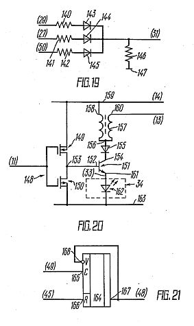
FIG. 19 is an electric schematic, showing the signal level clipper, according to the invention;
FIG. 20 is an electric schematic, showing the power amplifier, according to the invention and
FIG. 21 is an electric schematic, showing the timer, according to the invention.


Also published as: EP1053715 // EP1053715 // EP1053715 // RU2145186 // DE69824894
The present invention pertains to medicine and may be used in different scientific and technical fields where a biological subject is studied in order to obtain information about the complex resistance components (electrical conduction) of its tissues. The present invention is used for improving the measurement precision of the electrical conduction in organic tissues and relates to a method that comprises placing electrodes on predetermined sections of the subject's skin. A high-quality inductance coil is connected at a predetermined moment to a DC voltage supply and saturated with electromagnetic energy, after which the coil is instantaneously connected to the electrodes. Free oscillations occur in an oscillation circuit, wherein the elements of said circuit are the coil induction and the complex resistance of the tissues in the electrode gap. After measuring the parameters of said oscillations, it is possible to calculate the complex resistance components (electrical conduction) of the biological subject's tissues.
TECHNICAL FIELD
[0001] The invention relates to medicine, and particularly, to electroneuroadapting stimulators, and can be used for electrostimulation procedures for medical, prophylactic and diagnostic purposes.
BACKGROUND OF THE INVENTION
[0002] Nowadays there are widely applied electrostimulators - devices that act upon the body with electric signals of various form, duration and power.
[0003] Most of such devices are of little effect because they are not supplied with the control system of the body reaction upon the electrostimulation (for example, electrostimulators, protected by the USA patents, such as No3511641, MK pi . A61N1/36, in 1966; No3589370, MK pi . A61N1/36, in 1967; No4177819, MK pi . 4 A61N1/36, in 1979; author's certificate of USSR No865300, MK pi . 4 A61N1/36, in 1981; No1034750, MK pi . 4 A61N1/36, in 1983; No1351612, MK pi . 5 A61N1/37, in 1987).
[0004] More consummate are electrostimulators that allow to determine the time of the action by the reaction of the body upon the electrostimulation. Such devices were called electroneuroadapting stimulators or bioelectric regulators of psychosomatic homeostasis, as they regulate functional condition of the body with signals, similar to nerve impulses.
[0005] Known in the art is an electrostimulator described in the author's certificate of USSR No1817335, M PI K 6 A61N1/36, published in 1995, From.No24, that allows to set the action dose according to the body reaction upon this action. The electrostimulator consists of a pulsed oscillator, a modulator, a power amplifier, active and passive electrodes, a differentiator, an indicator, an envelope curve former, a multiplier, and an energy stimulus controller. The disadvantage of this electrostimulator is low accuracy of determining the body adaptation to the stimulating action that leads to reduction of the therapeutic effect of the device.
[0006] Electrostimulating device, protected by the patent of Russian Federation No2091089 MTTK 6 A61N1/36, published in 1997, From No27, that is unlike electrostimulator, protected by the author's certificate No1817335, additionally contains a signal conditioner, its inputs being connected to the outputs of the pulsed oscillator and the power amplifier, a time gate and a summator connected between the envelope curve former and the multiplier. It results in increasing of the speed of tracking of the body reaction upon the stimulating action, increasing of the dosage accuracy, and, consequently, the effect of treatment. The disadvantage of this electrostimulating device is low diagnostic capabilities, as diagnostics is carried out by frequency and intensity of flashes of the light-emitting diode indicator switched into the supply circuit of the power amplifier and, to a greater extent, depends upon the subjective perception of the person conducting the experiment.
[0007] A bioelectrical regulator of psychosomatic homeostasis, protected by the patent of Russian Federation No2068277, M PI K 6 A61N1/36, A61H39/00, published in 1996, From.No35, is supplied with higher accuracy of diagnostics (disclosing the character of pathology) and allows to prognosticate the effect of treatment.
[0008] This bioelectric regulator of psychosomatic homeostasis (electroneuroadapting stimulator) consists of a square-wave generator, connected in series; a stimulating signal forming unit; a switching-type amplifier supplied with a transformer output, connected to the active and passive electrodes; connected to the active electrode a concatenated half-wave rectifier, a measuring unit of duration and speed of the duration change of the first halt-wave of forced oscillations, a unit of indication and control; and the a set up unit of parameters of stimulating signals, connected to the second input of the stimulating signal forming unit. The accuracy of diagnostics is increased due to the duration of the first half-wave of damped oscillations testifying to the character and deepness of the pathology, and the speed of the duration change testifying to the results of treatment.
[0009] The disadvantage of this bicelectric regulator of psychosomatic homeostasis, used as prior art, consists in that due to the narrow-band output of the switching-type amplifier the change of the area of action leads to the change of the level of the stimulating signal that decreases the effect of treatment and accuracy of diagnostics.
SUMMARY OF THE INVENTION
[0010] Technical achievement of application of this invention consists in creation of electroneuroadapting stimulator providing higher effect of treatment and wider diagnostic capabilities due to coordination of the level of the stimulating signal with electrophysiological parameters of the body area being acted upon.
[0011] The above mentioned technical achievement is reached by the fact that electroneuroadapting stimulator comprising the power supply; the set up unit of parameters of stimulating signal; the active and passive electrodes; and the reactive load switching-type amplifier, the active electrode being connected to one of its taps, and the passive electrode being connected to the other tap; includes a microprocessor with the set up unit of parameters of the stimulating signal being connected to its first input port; an analog-to-digital converter with its input being connected to the active electrode, and the output being connected to the second input port of the microprocessor; and the reactive load adjusting unit with its input being connected to the first output of the microprocessor, that has its second output being connected to the input of the switching-type amplifier, the reactive load of the switching-type amplifier has a component of adjustment connected to the reactive load adjusting unit; the display unit is connected to the third output of the microprocessor; and the power supply is connected to one of the taps of the reactive load of the switching-type amplifier. In accordance with the preferred embodiment of the electroneuroadapting stimulator, the reactive load of the switching-type amplifier is performed as an inductance coil having a ferromagnetic core as a component of adjustment; and the reactive load adjusting unit contains a comparator, its first input being simultaneously the input of the adjusting unit, the second input being the input of the reference voltage and the output being connected to the control winding of the micromotor that has its shaft being connected through reducer to the ferromagnetic core that is installed into the inductance coil, so that it can be displaced.
[0012] The inductance coil is performed as two-sectional, with the correlation of windings in the sections from 2:1 to 10:1, the sections being connected in series. In the reactive load of the switching-type amplifier, performed as a two-sectional inductance coil, if the point of junction of the sections is the tap for connection of the power supply, the end of the section containing less windings is the tap for connection of the switching-type amplifier, and the end of the section containing more windings is the tap for connection of the active electrode. If the point of junction of the sections is the tap for connection of the active electrode, the end of the section containing less windings is the tap for connection of the switching-type amplifier; and the end of the section containing more windings is the tap for connection of the power supply and the passive electrode. If the point of junction of the sections is the tap for connection of the switching-type amplifier and the passive electrode, the end of the section containing less windings is the tap for connection of the power supply; and the end of the section containing more windings is the tap for connection of the active electrode. If the point of junction of the sections is the tap for connection of the switching-type amplifier, the end of the section containing less windings is the tap for connection of the power supply and the passive electrode; and the end of the section containing more windings is the tap for connection of the active electrode.
[0013] The inductance coil should have high quality of 500, the inductance within 1.0+/-0.9 henry, and the component of adjustment should provide the change of the inductance of the coil within 0.5...1.0 of the largest extremum.
BRIEF DESCRIPTION OF THE DRAWINGS
[0014] The invention is illustrated by the drawings shown in Fig.1...Fig.5.
[0015] Fig.1 shows a modular circuit of the claimed electroneuroadapting stimulator.
[0016] Fig.2 shows an electric circuit of the switching-type amplifier.
[0017] Fig.3 shows variants of connecting the two-sectional inductance coil as a reactive load of the switching-type amplifier.
[0018] Fig.4 shows a structural diagram of the reactive load adjusting unit of the switching-type amplifier.
[0019] Fig.5 shows an algorithm of operation of the microprocessor.


[0020] In Fig.1...Fig.5 there are numbered and lettered the following:
1 - set up unit of parameters of the stimulating signal;
2 - microprocessor;
3 - switching-type amplifier;
4 - reactive load of the switching-type amplifier;
5 - active electrode;
6 - passive electrode;
7 - analog-to-digital converter,
8 - reactive load adjusting unit of the switching-type amplifier;
9 - display unit;
10 - power supply;
11 - connection of the reactive load adjusting unit to the component of adjustment of the reactive load;
12 - input of the reactive load adjusting unit of the switching-type amplifier;
13 - input of the switching-type amplifier;
14 - output of connection of the switching-type amplifier to the reactive load;
15 - comparator,
16 - micromotor;
17 - reducer.
I - section of the inductance coil containing less windings;
II - section of the inductance coil containing more windings;
E - bus-bar of the power supply;
V1 - transistor (crystal triode);
V2 - crystal diode;
tM - duration of firing pulses;
TM - firing pulse repetition period;
NM - number of firing pulses in the series;
tau ccp - duration of the series of firing pulses;
tC.R. - duration of the stimulating action;
FC.D. - repetition frequency of the stimulating action;
tK- control time;
t - current time;
Um - amplitude of the first half-wave of free oscillations;
f - frequency of free oscillations;
T0.5 - time of damping of free oscillations to level of 0,5Um;
DELTA Um - change of the amplitude of the first half-wave during the duration of one series of firing pulses.
DESCRIPTION OF THE PREFERRED EMBODIMENT
[0021] The claimed electroneuroadapting stimulator (Fig.1) consists of connected in series set up unit 1 of parameters of the stimulating signal, a microprocessor 2 and a switching-type amplifier 3 with a reactive load 4, active 5 and passive 6 electrodes being connected to it. The input of the analog-to-digital converter (ADC) 7 that converts electric potential difference between the active 5 and passive 6 electrodes into a string of codes is connected to the active electrode 5. The output of ADC 7 is connected to the second port of the input of the microprocessor 2. The reactive load 4 contains a component of adjustment that changes its reactive component within 0.5...1.0 of the largest extremum. The component of adjustment of the reactive load 4 is connected to the reactive load adjusting unit 8, having its input connected to the second output of the microprocessor 2. To the third output of the microprocessor 2 there is connected a display unit 9, meant for displaying the parameters of firing pulses and the stimulating action. The power supply 10 provides precise supply for the switching-type amplifier 3 through the reactive load 4 and reference voltage for the adjusting unit 8. In the conventional stimulator, the switching-type amplifier 3 (Fig. 2) is represented as a transistor V1, its base (input 13) being delivered firing (enabling) pulses of normed amplitude and predetermined duration from the microprocessor 2, and its collector being connected through the protecting diode V2 to one of the taps of the reactive load 4 (output 14).
[0022] In accordance with a preferred embodiment of the electroneuroadapting stimulator, the reactive load 4 is performed as a two-sectional inductance coil (Fig. 3) with the correlation of windings in the sections from 2:1 to 10:1. As a component of adjustment, the inductance coil has a ferromagnetic core 11. In this case, the reactive load adjusting unit 8 (Fig. 4) contains a comparator 15, its first input being connected to the output 12 of the microprocessor 2, the second input being connected to the bus-bar E of the power supply 10, and the output being connected to the control winding of the micromotor 16, having its shaft mechanically connected through reducer 17 to the ferromagnetic core 11.
[0023] Variants of connection of the taps of the reactive load 4 are shown in Fig. 3a,..Fig. 3r.
[0024] Fig. 3a shows the point of junction of the sections 1 and 11 being connected to the passive electrode 6 and the bus-bar E of the power supply 10, the section I containing less windings being connected to the output 14 of the switching-type amplifier 3, and the section 11 containing more windings being connected to the active electrode 5. Fig. 36 shows the point of junction of the sections I and II being connected to the active electrode 5, the section 1 being connected to the output 14 of the switching-type amplifier 3, and the section II being connected to the passive electrode 6 and the bus-bar E of the power supply 10. Fig. 3a shows the point of junction of the sections I and II being connected to the output 14 of the switching-type amplifier 3 and the passive electrode 6, the section I being connected to the bus-bar E of the power supply 10, the section II being connected to the active electrode 5. Fig. 3r shows the point of junction of the sections I and II being connected to the output 14 of the switching-type amplifier 3, the section I being connected to the bus-bar E of the power supply 10 and the passive electrode 6, the section II being connected to the active electrode 5.
[0025] The principle of operation of the electroneuroadapting stimulator is based upon the fact that stimulating signals, that act upon the tissue structure under the electrode are electric oscillations in an oscillatory circuit formed by connected in series reactive load and capacitive and reactive components of impedance of the tissue structure under the electrode, appearing together with stopping of action of firing pulse on the input of the switching type amplifier 3 after it has been disconnected. Parameters of these oscillations (amplitude, frequency, damping time) to 90...95% depend only upon electrophysiological condition of the tissue structure under the electrode.
[0026] It depends on the constancy of level of oscillations energy, stability of the parameters of the reactive load and elimination of influence of impedance of contact "electrode - tissue under the electrode". Stability of the parameters of the reactive load is achieved by a high-quality inductance coil (with high quality over 500). Constancy of the oscillations energy is achieved due to being equal to the energy accumulated in the reactive load with the switching-type amplifier 3 being switched on and depends only upon the duration of firing pulse. To exclude any influence upon the parameters of the electric oscillations of impedance of contact "electrode - tissue under the electrode", it is enough to use the electrodes having the contact area over 5 mm<2> and choose resonance frequency of the oscillatory circuit over 100 kHz at the expense of the parameters of the reactive load. Under such conditions, the value of the capacitive component of impedance of contact "electrode - tissue under the electrode" is two orders less than the value of the capacitive component of impedance of the tissue structures under the electrode. Thus, with high stability of firing pulses, characteristics of the switching-type amplifier 3, the parameters of the reactive load 4, that can be easily realized under modern technical conditions, and, provided that the contact area is over 5 mm<2> and the resonance frequency of the oscillatory circuit is over 100 kHz, the parameters of free oscillations in the oscillatory circuit will reflect biochemical processes and physical condition of the tissue structures under the electrode with high accuracy, as the active component of impedance of these structures characterized blood filling and admittance of the intertissular medium and capacitive component characterizes cellular and intercellular polarization. Disbalance of the biochemical processes under the influence of the stimulating signal will cause the changing of both active and reactive component of the impedance of the tissue structures under the electrode. In its turn, this changing causes changing of the parameters of free oscillations in the oscillatory circuit formed by series connection ot the inductance of the reactive load 3 and the capacitive component of impedance of the tissue structures under the electrode. Measuring the parameters of these oscillations allows to judge about the body reaction upon the stimulating action. When the balance of the biochemical processes is achieved, the stimulating action stops its influence upon the value of impedance of the tissue structures under the electrode and it should be stopped, as overdose of the stimulating action may lead to negative result. Therapeutic effect of applying the electroneuroadapting stimulator of psychosomatic homeostasis in many respects depends upon the accuracy of determining the moment when the balance of the biochemical processes is achieved, i.e. when the impedance of the tissue structures under the electrode stops changing under the influence of the stimulating signal.
[0027] Operation of the claimed electroneuroadapting stimulator of psychosomatic homeostasis is described taking into account the algorithm of operation of the microprocessor 2 shown in Fig. 5.
[0028] Switching on the electroneuroadapting stimulator is carried out with the set up unit 1 of parameters of the stimulating signal that is performed as a push-button control panel and the parameters of firing pulses - duration of firing pulses tH, firing pulse repetition period TH, number of firing pulses in series NH, duration of the series of firing pulses tau ccp, duration of the stimulating action tC.R., and repetition frequency of the stimulating action FC.R. are recorded into on-line storage of the microprocessor 2. After the parameters of firing pulses have been recorded into the on-line storage of the microprocessor 2, the timer is activated, control time and current number of pulse are set to zero and there starts counting of the current time and comparing it with the control time. If the current time is equal to the control one (t-tk=0), firing pulse-shaping circuit is started and it is reset when the difference between the current and control time is equal to tH. Pulses with normed amplitude are delivered from the output of the firing pulse-shaping circuit to the input 13 of the switching-type amplifier 3 and switch it on. During action of firing pulse, there is conducted electric current through the inductance coil of the reactive load 4 and inside the inductance coil there is accumulated electromagnetic energy that can be determined by the following expression:
EMI8.1
L - is value of the inductance of the reactive load 4,
E - is voltage of the power supply 10,
r0 - is internal resistance of the power supply 10,
rL - is ohmic resistance of the reactive load 4,
rK pi - is resistance of the open switching-type amplifier 3,
tH - is duration of the pulse,
[0029] After the action of firing pulse has been stopped, the switching-type amplifier 3 is switched off and in the oscillatory circuit, formed by series connection of the inductance of the reactive load 4, equivalent capacitance C3 and equivalent ohmic resistance R3 of the tissue structures under the electrode, there appear electric oscillations that can be described by the following expression:
EMI8.2
Um - is amplitude of the first half-wave of oscillations;
alpha - is speed of oscillation damping;
f - is frequency of oscillations;
L is inductance of the reactive load 4;
C3 - is equivalent capacitance of the tissue structures under the electrode;
E - is voltage of the power supply 10;
r0 - is internal resistance of the power supply 10;
rL - is ohmic resistance of the reactive load 4;
rK pi - is resistance of the switching-type amplifier 3 being switched on;
tH - is duration of the firing pulse;
R3 - is equivalent ohmic resistance of the tissue structures under the electrode.
[0030] From the output 7 of ADC, voltage codes between the active 5 and passive 6 electrodes are read with the frequency that is 10 - 20 times higher than the oscillations frequency and are delivered to the microprocessor 2. In the microprocessor 2, supplied with special subprogram, there are determined Um - amplitude of the first half-wave of oscillations, f - frequency of oscillations and T0.5 - time of damping of amplitude of oscillations to level 0.5. Then the control time is set equal to the time of start of the next firing pulse (tx DELTA t-tM+TM) and 1 is added to the current number of the pulse (N DELTA N+1); after that the new number of the pulse is compared with the set value of pulses in N series and, if they are not equal, another firing pulse is formed and new values Um,f, and T0.5 are determined; if they are equal, the control time is set equal to the time of start of new series of firing pulses (tK DELTA t-TM(N-1)-tk+ tau cep), the current number of the pulse is set equal to zero (N DELTA 0) and subprogram of trimming of the inductance coil of the reactive load 4 is started. According to this program, change Um during the duration of series of firing pulses is determined and, in accordance with the value of this change, PWM voltage delivered to the input 8 of the reactive load adjusting unit is corrected, and with the help of the component of adjustment - the ferromagnetic core 11 the inductance of the inductance coil is being changed until the value Um is not equal to the initial value, This allows to increase the accuracy of determining the body reaction upon the stimulating action, as when the equivalent capacitance of the impedance of the tissue structures under the electrode is being changed, wave resistance of the oscillatory circuit is maintained constant.
[0031] The sign of no reaction of the body upon the stimulating action and termination of the stimulation is determined by constancy of at least one of parameters of electric oscillations (Um, f, and T0.5) during the next series of firing pulses, i.e. when the following condition is executed:
DELTA Um=Um1 - UmNH = 0, or DELTA f = DELTA f1 - DELTA fNH = 0, or DELTA T0.5 = T<1>0.5 - T<N>0.5 = 0;
DELTA Um - is change of the amplitude of the first half-wave of electric oscillations during the duration of series of firing pulses;
Um1 - is the amplitude of the first half-wave of electric oscillations from the first pulse in the series;
UmNH - is the amplitude of the first half-wave of electric oscillations from the last pulse in the series;
DELTA f- is the change of the frequency during the series of firing pulses;
f1 - is the frequency of electric oscillations after the first pulse in the series;
fNH - is the frequency of electric oscillations after the last pulse in the series;
DELTA T0.5 - is the change of time of damping of amplitude of free oscillations to level 0,5 during the duration of the series of firing pulses;
T<1>0.5 - is the time of damping of amplitude of oscillations to level 0,5 after the first pulse in the series;
T<N>0.5 - is the time of damping of amplitude of oscillations to level 0,5 after the last pulse in the series.
[0032] Constancy of one of the parameters of electric oscillations during the action of the stimulating signals (NH signals with pulse repetition period TH) testifies to the electrophysiological condition of the tissue structures under the electrode being unchanged or changed within the sensitivity of the device; the further action may convert it from tonic into stress one and eliminate therapeutic effect.
[0033] Execution of one of those conditions will lead to switching off of the device.
[0034] In accordance with the subprogram of indication and diagnostics, there are generated signals for reflecting the characteristics allowing to judge objectively about the electrophysiological condition of the tissue structures under the electrode before the stimulating action and after that. Such characteristics are power level of the stimulating action (tH and NH are reflected), values of the active and reactive components of impedance of the tissue under the electrode at the beginning and at the end of the action (there reflected R3, C3, DELTA R3 and DELTA C3 - the final values of the active and reactive components of impedance and their change during the time of the action).
[0035] The effect of therapeutic action is increased due to the increase of accuracy of dosage of the stimulating action. Diagnostic capabilities are enlarged due to objectivizing of the results of the action.
[0036] The claimed electroneuroadapting stimulator can be easily made of the components available in industry. The microprocessor 2 ADC 7 can be made of programmable logic devices FLEX 10k, the switching-type amplifier can be made of KT815 transistor. An inductance coil with the cup core E-18, E-22 can be used as the inductance coil.
Inventor : KARASEV ALEXANDR ALEXANDROVICH [RU]
The present invention pertains to medicine and may be used in different scientific and technical fields where a biological subject is studied in order to obtain information about the complex resistance components (electrical conduction) of its tissues. The present invention is used for improving the measurement precision of the electrical conduction in organic tissues and relates to a method that comprises placing electrodes on predetermined sections of the subject's skin. A high-quality inductance coil is connected at a predetermined moment to a DC voltage supply and saturated with electromagnetic energy, after which the coil is instantaneously connected to the electrodes. Free oscillations occur in an oscillation circuit, wherein the elements of said circuit are the coil induction and the complex resistance of the tissues in the electrode gap. After measuring the parameters of said oscillations, it is possible to calculate the complex resistance components (electrical conduction) of the biological subject's tissues.
TECHNICAL FIELD
[0001] The invention relates to the medicine and can be used in various fields of science and engineering that require information about the components of the complex impedance of the biological object's tissue.
BACKGROUND OF THE INVENTION
[0002] Lately, the trends of scientific and diagnostic studies of biological objects that make provision for analysis of parameters of measured complex impedance of various body areas of a biological object, so-called impedance methods, are being more and more widely practised. The main point of these methods is to measure the electrical parameters of the skin of a biological object in various body areas and compare them with the already studied parameters of the standard skin sample. Having determined to what extend these parameters deviate from the standard, a conclusion can be drawn about skin condition, diseases and other phenomena in a living organism...
[0021] The disadvantage of the prior art lies in its low accuracy because of instability of frequency of self-excited oscillator and the amplitude of these oscillations being affected by the resistance of skin under the electrodes.
[0022] The aim of the invention is to increase the accuracy of measuring the conductivity of the biological object's tissue.
SUMMARY OF THE INVENTION
[0023] The above mentioned aim is achieved by the fact that in the method for measuring the conductivity of the biological object's tissue that consists in superimposing the electrodes upon the skin area under examination and determining the components of the complex impedance of the conductivity of the biological object's tissue by parameters of electrical oscillations in the oscillatory circuit, including as its component the complex impedance of the tissue between the electrodes, the conductance coil preliminarily saturated with electromagnetic energy is connected to the electrodes and the components of the biological object's tissue are determined by the parameters of free oscillations that set on in the oscillatory circuit, including as its components the inductance of the inductance coil, the ohmic resistance and the capacitance of the biological object's tissue...
[0029] The feature of the invention, i.e. the connection of saturated with electromagnetic energy inductance coil to the electrodes placed upon the biological object's skin area under examination, in order to determine the components of the complex impedance of the biological object's tissue, is unknown from the available prior art. Determining of the components of the complex impedance by parameters of free oscillations in the oscillatory circuit, having the inductance of the inductance coil saturated with electromagnetic energy and the impedance of the biological object's tissue between the electrodes is unknown as well.
BRIEF DESCRIPTION OF THE DRAWINGS
[0030] The essence of the applied method is revealed by the description of operation of the device (for the functional diagram of the device see Fig.1) that provides the applied method for measuring the conductivity of the biological object's tissue being put into practice.

The device consists of high-quality conductance coil 1, standard source of constant voltage 2, switch 3, active electrode 4 and passive electrode 5, that are put upon the biological object's skin area 6 under examination, in order to measure the conductivity of the tissue 7 between the electrodes. The passive electrode 5 is connected to a common bus 8, that, in its turn, has one of the terminals of the source 2 and the lead of the conductance coil 1 being connected to it. The unit of control and measurement connected to the tap of the conductance coil 1 provides the measurement of the parameters of free oscillations in the oscillatory circuit...
Alexandr
REVENKO, et al. Patents
RU
1817335
The invention belongs
to medicine, to electro-stimulation. The aim of the invention is
to increase the precision of dosing of influence according
patient’s response. The device has few elements and the
differentiating element, which manages the characteristics of
signals.RU
72402
A construction for
ply-factors influence.RU
2135226
The invention belongs
to medicine technology, in particular to electronic devices of
electro-stimulation and intended for the therapeutic non –
invasive individual and dosed influence. This type of influence
determines on choosing zones and time cycle. The influence
realizes to a skin by electrical impulses with aim of regulation
to the human physiological systems and achieving anesthetic
effect.1. The ways of influences, the most optimal for SCENAR therapy were defined: local, symmetrical, horizontal, general zone, where the reactions of the body are defined: IR, DR, D, 0. An operator consecutively determines body reactions with next influence depending of increasing of the patient response.
2. The algorithm of influence of SCENAR therapy depends of two comparing reactions and next influence is made to the high reaction. Few different ways are determined of this algorithm.
FIELD: medicine. ^ SUBSTANCE: method involves applying primary treatment using pulsating SCENAR current sequentially arranging the device in zone of complaint and additionally in zone arranged symmetrically to the zone of complaint and horizontally equidistant from vertebral column line. Sequential positioning is carried out with initial SCENAR response values being determined until a value differing from the previous ones is detected. Individually dosed SCENAR treatment factor value is determined in position distinguished by maximum value of initial SCENAR response value from passed positions. The initial SCENAR response values measurement is continued in determining individually dosed SCENAR treatment factor values in positions distinguished by growing initial response values.; Current SCENAR response values are determined in the positions characterized by growing individually dosed SCENAR treatment factor values where organism response to pulsating SCENAR current vanishes when electric skin tissue impedance stops changing. Zone of maximum current SCENAR response value characterized in organism response to pulsating SCENAR current action vanishing is selected as optimum for applying SCENAR therapy. The same is done in one of two positions having individually dosed SCENAR treatment factor values characterized in organism response to pulsating SCENAR current action vanishing. The position is distinguished by greater value of individually dosed SCENAR treatment factor.; Zone of maximum current SCENAR response value characterized in organism response to pulsating SCENAR current action vanishing is selected as optimum for applying electric pulse SCENAR therapy. ^ EFFECT: enhanced effectiveness in determining zone localization optimum for applying electric pulse SCENAR therapy.
RU2289388
METHOD OF ACUPUNCTURE DIAGNOSTICS AND METHOD OF CORRECTION OF FUNCTIONAL STATE OF ORGANISM
METHOD OF ACUPUNCTURE DIAGNOSTICS AND METHOD OF CORRECTION OF FUNCTIONAL STATE OF ORGANISM
[
PDF ]
1. The ways of measuring of meridians points were determined, also the conclusion of functional and adaptation state of organism were invented.
2. The different manners of the influence to the functional and adaptation state of the body with SCENAR therapy and therapeutic blanket were invented.
FIELD: medicine; reflex diagnostics of human body's functional state; reflex therapy. ^ SUBSTANCE: methods can be used for diagnostics and correction of state of organism by means of electro-stimulation. Method of acupuncture diagnostics is based upon measurement of electric conductivity of skin in 24 biologically active representative points of 12 pair meridians of acupuncture skin areas, upon building reference spreadsheet of electric conductivities and individual corridor. Electric conductivity is estimated on the base of direction values which go out of limits of individual corridor borders.; Borders of individual corridor are found from relations of T=Ca.Kt+Delta1 and L= Ca.Kl-Delta2, where T is top border of individual corridor, Ca is average normalized electric conductivity of all meridians, Kt =1,05-1,2, namely normalizing coefficient of top border of individual corridor, Delta1=2-5 is value of tolerance which compensates errors in measurement for determination of top border of individual corridor, L is lower border of individual corridor, Kl =0,8-0,95 is normalizing coefficient of lower border of individual corridor, Delta2=2-5 is value of tolerance which compensates errors in measurement for determination of lower border of individual corridor.; Pair meridians are found where one biologically active representative point has electric conductivity coinciding with individual corridor, and the other has electric conductivity being higher than top and being lower than lower border of individual corridor. Method diagnostics has higher precision due to determination of borders of individual corridor of any person. Method of correction of functional state of organism is based upon measurement of electric conductivity of skin in 24 biologically active points of 12 pair meridians of acupuncture skin areas, upon building of normalization spreadsheet of electric conductivities and upon building of individual corridor, and upon evaluation of electric conductivity from direction of values which go out of borders of individual corridor.; Correction of functional state of organism is preformed due to electric influence onto biologically active points. For the purpose after the individual corridor built, the number of meridians where electric conductivity of biologically active representative points exceeds top border of individual corridor and number of meridians where electric conductivity is lower than low border of individual corridor as well as the value of meanings which is smaller and which pair meridians belong to the smaller quantity. To make stimulating influence, biologically active points are chosen of those pair meridians which meet the three conditions.; First condition relates to meridians where one biologically active representative point has electric conductivity which coincides with values of individual corridor of standard and the other biologically active representative point has electric conductivity being higher or lower than lower border of individual corridor. Second condition relates to meridians which belong to smaller quantity of those ones where electric conductivities of biologically active representative pints go out of borders of individual corridor. The third condition relates to meridians where difference in electric conductivities of biologically active representative points has maximal value.; If individual corridor is higher than averaged corridor of norm for healthy person, then electric influence onto biologically active representative points of selected meridian is carried out at excitation mode, and if individual corridor is lower than - in mode of brake. ^ EFFECT: improved efficiency of influence due to correct selection of points to make influence on.
The invention belongs to medicine technology, in particular to electronic devices of electro-stimulation and intended for the therapeutic non – invasive individual and dosed influence. This type of influence determines on choosing zones and time cycle. The influence realizes to a skin by electrical impulses with aim of regulation to the human physiological systems and achieving anesthetic effect. The technical result of the invention is increasing of the functional abilities of the device because the operator can choose parameters of impulses.
FIELD: medical engineering. SUBSTANCE: electrostimulator is used for noninvasive action on sections of man's cutaneous covering by electric pulses for rendering of general control effect on physiological systems of organism. Electrostimulator has square-pulse generator 2, power amplifier 5 and two electrodes 10 and 11. In addition, it has first sawtooth-voltage generator 4, power setting assembly 5, trapezoidal signal generator 6, indicator 12, signal form control assembly 11, and second sawtooth-voltage generator 16. EFFECT: extended functional capabilities, improved therapeutic effect.
The invention belongs to medicine technology, in particular to electronic devices of electro-stimulation and intended for the therapeutic non – invasive individual and dosed influence. This type of influence determines on choosing zones and time cycle. The influence realizes to a skin by electrical impulses with aim of regulation to the human physiological systems and achieving anesthetic effect. The technical result of the invention is increasing of the functional abilities of the device because the operator can choose parameters of impulses. Also technical result is increased because of BFB of local physiological reactions on the grounds of analysis of free vibration’s waves.
Medical equipment, in particular, electronic devices for electrostimulation of human organism, applicable for action of electric pulses on areas of human dermatic integument with the aim of exerting a generally regulatory influence on human physiologic systems and attaining an analgetic effect. SUBSTANCE: the electrostimulator has a square-wave unit, control unit, energy action control unit, output unit, passive and active electrodes, pulse burst shaping unit, feedback unit, individual norm storage unit and a sounding signal parameter recording unit. EFFECT: expanded functional abilities attained due to introduction of local, physiologic feedback on the basis of analysis of half-waves of free oscillations of stimulating pulses, improved therapeutic effect