Description
BACKGROUND OF THE INVENTION
1. Field of the Invention
The present invention relates generally to internal
combustion engines and, more specifically, it relates to a
steam enhanced double piston cycle engine (SE-DPCE) that is
more efficient than conventional combustion engines.
2. Description of the
Related Art
It can be appreciated that internal combustion engines are
ubiquitous today and have been in use for over 100 years.
Typically, an internal combustion engine includes one or
more cylinders. Each cylinder includes a single piston that
performs four strokes, commonly referred to as the intake,
compression, combustion/power, and exhaust strokes, which
together form a complete cycle of conventional pistons.
The main problem with a conventional internal combustion
engine is low fuel efficiency. It is estimated that more
than one half of the potential fuel thermal energy created
by conventional engines dissipates through the engine
structure without adding any useful mechanical work. A major
reason for this thermal waste is the essential cooling
requirements of conventional engines. The cooling system
(e.g., radiator) alone dissipates heat at a greater rate and
amount than the total heat actually transformed into useful
work. Another problem with conventional internal combustion
engines is their inability to increase efficiencies while
using heat regeneration or recycling methods to provide
higher combustion temperatures.
Another reason why conventional engines suffer from
efficiency problems is that the high-temperature in the
cylinder during the intake and compression strokes makes the
piston work harder and, hence, less efficient during these
strokes.
Another disadvantage associated with existing internal
combustion engines is their inability to further increase
combustion temperatures and compression ratios; although
raising chamber temperatures during the power stroke and
increasing compression ratios would improve efficiencies.
Another problem with conventional engines is their
incomplete chemical combustion process causing harmful
exhaust emissions.
While these devices may be suitable for the particular
purpose to which they address, they are not as efficient as
the proposed SE-DPCE that utilizes temperature
differentiated dual cylinders that divide the conventional
four strokes of a piston into two low temperature strokes
(intake and compression) and two high temperature strokes
(power and exhaust), performed by each of the respective
dual pistons, while further utilizing the heat generated by
the high temperature strokes to generate steam, which is
used to convert additional thermal energy to mechanical
energy.
Although others have previously disclosed dual-piston
combustion engine configurations, none provide the
substantial efficiency and performance improvements of the
present invention. For example, U.S. Pat. No. 1,372,216 to
Casaday discloses a dual piston combustion engine in which
cylinders and pistons are arranged in respective pairs. The
piston of the firing cylinder moves in advance of the piston
of the compression cylinder. U.S. Pat. No. 3,880,126 to
Thurston et al. discloses a two-stroke cycle split cylinder
internal combustion engine. The piston of the induction
cylinder moves somewhat less than one-half stroke in advance
of the piston of the power cylinder. The induction cylinder
compresses a charge, and transfers the charge to the power
cylinder where it is mixed with a residual charge of burned
products from the previous cycle, and further compressed
before igniting. U.S. Pat. Application No. 2003/0015171 A1
to Scuderi discloses a four-stroke cycle internal combustion
engine. A power piston within a first cylinder is connected
to a crankshaft and performs power and exhaust strokes of
the four-stroke cycle. A compression piston within a second
cylinder is also connected to the crankshaft and performs
the intake and compression strokes of the same four-stroke
cycle during the same rotation of the crankshaft. The power
piston of the first cylinder moves in advance of the
compression piston of the second cylinder. U.S. Pat. No.
6,880,501 to Suh et al. discloses an internal combustion
engine that has a pair of cylinders, each cylinder
containing a piston connected to a crankshaft. One cylinder
is adapted for intake and compression strokes. The other
cylinder is adapted for power and exhaust strokes. U.S. Pat.
No. 5,546,897 to Brackett discloses a multi-cylinder
reciprocating piston internal combustion engine that can
perform a two, four, or diesel engine power cycle.
However, these references fail to disclose how to
differentiate cylinder temperatures to effectively isolate
the firing (power) cylinders from the compression cylinders
and from the surrounding environment. The references further
fail to disclose how to minimize mutual temperature
influence between the cylinders and the surrounding
environment. In addition, the references fail to disclose
engine improvements that further raise the temperature of
the firing cylinder and lower the temperature of the
compression cylinder beyond that of conventional combustion
engine cylinders to enhance engine efficiency and
performance. Specifically, minimizing temperature of the
compression cylinder allows for a reduced compression work
investment, while increasing temperature in the power
cylinder allows for increased heat regeneration. In
addition, the separate cylinders disclosed in these
references are all connected by a transfer valve or
intermediate passageway of some sort that yields a volume of
"dead space" between cylinders, permitting gases to
accumulate in between cylinders and further degrading the
efficiency of the engine. Additionally, none of these prior
art references discussed above teach an opposed or "V"
cylinder and crankshaft configuration that minimizes dead
space between cylinders while isolating the cylinders to
maintain an improved temperature differential between the
cylinders. Finally, none of these prior art references
disclose splitting the combustion/power chamber into two
separate chambers and utilizing steam energy in an outer
chamber for additional engine efficiency and work.
Additionally, none of the prior art references disclose or
suggest a secondary system, enveloping the primary
combustion chamber, that converts the excessive thermal
energy produced by the hot chamber into additional kinetic
energy.
U.S. Pat. No. 5,623,894 to Clarke discloses a dual
compression and dual expansion internal combustion engine.
An internal housing containing two pistons moves within an
external housing forming separate chambers for compression
and expansion. However, Clarke contains a single chamber
that executes all of the engine strokes preventing isolation
and/or improved temperature differentiation of cylinders
such as those disclosed in the present invention. Clarke
also fails to disclose forming a separate chamber for
utilizing additional energy (e.g., heated air or steam)
generated by excess engine heat.
U.S. Pat. No. 3,959,974 to Thomas discloses a combustion
engine comprising a combustion cylinder formed in part of
material which can withstand high temperatures in a ringless
section containing a power piston and connected to a ringed
section maintaining a relatively low temperature containing
another piston. However, elevated temperatures in the entire
Thomas engine reside not only throughout the combustion and
exhaust strokes, but also during part of the compression
stroke. Further, Thomas fails to disclose a method of
isolating the engine cylinders in an opposed or "V"
configuration to permit improved temperature differentiation
and discloses an engine containing substantial dead space in
the air intake port connecting the cylinders. Finally,
Thomas fails to disclose forming a separate chamber for
utilizing additional energy (e.g., heated air or steam)
generated by excess engine heat.
In these respects, the SE-DPCE according to the present
invention substantially departs from the conventional
concepts and designs of the prior art, and in doing so
provides a dramatically improved internal combustion engine
that is more efficient than conventional internal combustion
engines.
SUMMARY OF THE INVENTION
In view of the foregoing disadvantages inherent in the known
types of internal combustion engine now present in the prior
art, the newly proposed invention provides a SE-DPCE
combustion engine utilizing temperature differentiated
cylinders that converts fuel into energy or work in a more
efficient manner than conventional combustion engines, as
well as converting excessive engine heat into additional
useful work.
In one embodiment of the invention, a steam enhanced dual
piston cycle engine (SE-DPCE) utilizes temperature
differentiated cylinders that convert fuel into energy or
work in a more efficient manner than conventional combustion
engines, as described in U.S. provisional application Ser.
No. 60/661,195, the entirety of which is incorporated by
reference herein, and further enhances the DPCE apparatus by
utilizing engine heat to create and convert steam energy
into additional useful engine work.
In one embodiment of the present invention, the engine
includes a first cylinder coupled to a second cylinder, a
first piston positioned within the first cylinder and
configured to perform intake and compression strokes, and a
second piston positioned within the second cylinder and
configured to perform power and exhaust strokes.
Alternatively, the first and second cylinders can be
considered as a single cylinder having two separate chambers
coupled to each other within the single cylinder, wherein
the first piston resides in the first chamber and the second
piston resides in the second chamber.
In a further embodiment, the engine further includes an
intake valve coupled to the first cylinder, an exhaust valve
coupled to the second cylinder and an interstage valve that
couples an internal chamber of the first cylinder to an
internal chamber of the second cylinder.
In a further embodiment, the engine includes two piston
connecting rods, a compression crankshaft, a power
crankshaft and two crankshaft connecting rods. The
connecting rods connect respective pistons to their
respective crankshafts. The compression crankshaft converts
rotational movement into reciprocating movement of the first
piston. The power crankshaft converts second piston
reciprocating movement into engine rotational output
movement. The crankshaft connecting rods transfer the power
crankshaft rotation into compression crankshaft rotation.
In a further embodiment, the engine includes a fuel
injector, water/steam inlet valves and water/steam exhaust
valve. The first compression cylinder houses the compression
piston, the intake valve, and part of the interstage valve.
The second power cylinder comprises two separate cylinders:
an outer cylinder and an inner cylinder. Within the outer
and inner cylinder resides a dual piston: a disc shaped
inner piston and a ring shaped outer piston. In addition,
the second power cylinder includes an exhaust valve, an
outer exhaust shell (wrapped exhaust pipe), a heat isolation
layer, part of the interstage valve, fuel injector, spark
plug, steam/water valve (and/or injectors), and
steam/water/air exhaust valve. The first compression piston
performs the intake and the compression engine strokes. The
inner power piston performs the fuel combustion power stroke
and the exhaust (burned gaseous) relief stroke. The outer
power piston produces power and absorbs engine excessive
heat by utilizing hot compressed air with or without
steam/water. The connecting rods connect the compression
piston and both power pistons to their respective
crankshafts. The compression crankshaft converts rotational
movement into compression piston reciprocating movement. The
power crankshaft converts inner and outer power pistons
reciprocating movement into engine rotational output
movement. The crankshaft connecting rods transfer the power
crankshaft rotation into compression crankshaft rotation.
In another embodiment, the engine intake valve includes a
shaft having a conic shaped sealing surface, same as used in
most four stroke engines. The exhaust valve includes a shaft
having a conic shaped sealing surface, same as in most four
stroke engines. The interstage valve (in the preferable
embodiment) is composed of a shaft having a conic shaped
sealing surface.
In another embodiment, a method of improving combustion
engine efficiency includes separating the intake and
compression chamber (cool strokes) from the combustion and
exhaust chamber (hot strokes), and thus enabling reduced
temperature during intake and compression strokes and
increased temperature during the combustion stroke, thereby
increasing engine efficiency.
In a further embodiment, a method of improving engine
efficiency includes minimizing or reducing the temperature
during intake and compression strokes. The lower the
incoming and compressed air/charge temperature is, the
higher the engine efficiency will be.
In yet another embodiment, a method of improving engine
efficiency includes regenerating and utilizing exhaust
thermal energy.
In a further embodiment, a dual piston combustion engine is
provided that greatly reduces external cooling requirements
which in turn increases the potential heat available for
heat output work conversion during the power stroke, which
also burns fuel more efficiently and thereby decreases
harmful emissions.
In another embodiment, a method of providing an improved
efficiency combustion engine includes performing the intake
and compression in a first cylinder and performing the power
and exhaust strokes in a second cylinder, wherein the first
cylinder is maintained at a cooler temperature than the
second cylinder. In a further embodiment, the method also
includes injecting the compressed air and fuel mixture from
the first cylinder into the second cylinder, thereby cooling
the second cylinder.
In another embodiment, a steam enhanced dual piston
combustion engine additionally comprises a ring-shaped
chamber in the combustion cylinder to receive compressed
gases and/or liquids utilizing excess engine heat to produce
additional power and increase engine efficiency. In a
further embodiment a steam enhanced dual piston combustion
engine additionally comprises a ring-shaped chamber in the
compression cylinder to facilitate efficient transfer of
compressed gases and/or liquids to the steam chamber. In an
additional embodiment, a steam enhanced dual piston
combustion engine contains two separate power producing
systems, with a primary system utilizing fuel-air combustion
and secondary system utilizing excess engine heat for steam
power generation.
BRIEF DESCRIPTION OF THE
DRAWINGS
FIG. 1 is a
simplified cross-sectional side view of a DPCE apparatus, in
accordance with one embodiment of the invention, wherein the
crankshaft angle is illustrated at 270 degrees.
FIG. 2 is a
simplified cross-sectional side view of the DPCE apparatus
of FIG. 1, wherein the crankshaft angle is illustrated at
315 degrees.
FIG. 3 is a
simplified cross-sectional side view of the DPCE apparatus
of FIG. 1, wherein the crankshaft angle is illustrated at
330 degrees.
FIG. 4 is a
simplified cross-sectional side view of the DPCE apparatus
of FIG. 1, wherein the crankshaft angle is illustrated at 0
degrees.
FIG. 5 is a
simplified cross-sectional side view of the DPCE apparatus
of FIG. 1, wherein the crankshaft angle is illustrated at 45
degrees.
FIG. 6 is a
simplified cross-sectional side view of the DPCE apparatus
of FIG. 1, wherein the crankshaft angle is illustrated at 90
degrees.
FIG. 7 is a
simplified cross-sectional side view of the DPCE apparatus
of FIG. 1, wherein the crankshaft angle is illustrated at
135 degrees.
FIG. 8 is a
simplified cross-sectional side view of the DPCE apparatus
of FIG. 1, wherein the crankshaft angle is illustrated at
180 degrees.
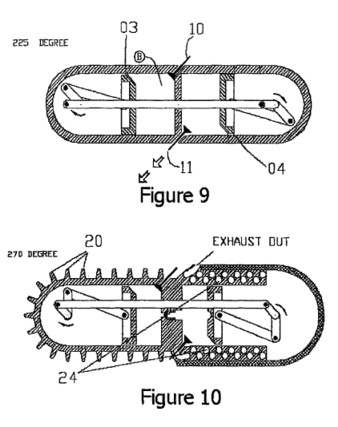
FIG. 9 is a
simplified cross-sectional side view of the DPCE apparatus
of FIG. 1, wherein the crankshaft angle is illustrated at
225 degrees.
FIG. 10 is a
simplified cross-sectional side view of a DPCE apparatus
having an air-cooled compression cylinder and an
exhaust-heated power cylinder, in accordance with one
embodiment of the invention.
FIG. 11 is a
simplified cross-sectional side view of a DPCE apparatus
having a water-cooled compression chamber and an
exhaust-heated power chamber, in accordance with one
embodiment of the invention.
FIG. 12 is a
3-Dimensional (3D) simplified illustration of the DPCE
compression and power pistons, in accordance with one
embodiment of the invention.
FIG. 13 is a 3D
simplified illustration of the DPCE compression and power
crankshafts, in accordance with one embodiment of the
invention.
FIG. 14 is a 3D
simplified illustration of the DPCE compression and power
crankshafts, in accordance with one embodiment of the
invention.
FIG. 15 is a 3D
simplified illustration of a DPCE crankshafts system,
illustrating a crankshaft connecting rod, in accordance with
one embodiment of the invention.
FIG. 16 is a 3D
simplified illustration of a DPCE crankshaft system, having
two crankshaft connecting rods, in accordance with one
embodiment of the invention.
FIG. 17 is a 3D
simplified illustration of a DPCE crankshaft system,
illustrating dissimilar crankshaft angles, in accordance
with one embodiment of the invention.
FIG. 18 is a 3D
simplified illustration of a DPCE crankshaft system, having
one crankshaft connecting rod in combination with a timing
belt (or a chain or a V-shaped belt), in accordance with one
embodiment of the invention.
FIG. 19 is a 3D
simplified illustration of a DPCE crankshaft system having
solely a timing belt (or a chain or a V-shaped belt), in
accordance with one embodiment of the invention.
FIG. 20 is a 3D
simplified illustration of a DPCE crankshaft system, having
crankshaft gear wheels as the connecting mechanism, in
accordance with one embodiment of the invention.
FIG. 21 is a 3D
simplified illustration of a DPCE crankshaft system, having
crankshaft gear wheels as the connecting mechanism, in
accordance with another embodiment of the invention.
FIG. 22 is a
simplified cross-sectional view of an interstage valve, in
accordance with one embodiment of the invention.
FIG. 23 is a
simplified interstage relief valve cross-sectional
illustration, in accordance with one embodiment of the
invention.
FIG. 24 is a
simplified cross-sectional illustration of a semi automatic
interstage valve, in accordance with one embodiment of the
invention.
FIG. 25 is a
simplified cross-section illustration of a DPCE apparatus
having supercharge capabilities, in accordance with one
embodiment of the invention.
FIG. 26 is a 3D
simplified illustration of a DPCE apparatus having the
compression cylinder and the power cylinder on different
planes, in accordance with one embodiment of the invention.
FIG. 27 is a 3D
simplified illustration of a DPCE apparatus in which both
cylinders are parallel to each other and both pistons move
in a tandem manner, in accordance with one embodiment of the
invention.
FIG. 28 is a
simplified cross-sectional side view of a SE-DPCE apparatus,
in accordance with one embodiment of the invention.
FIG. 29 is a 3D
simplified cross-sectional view of inner and outer power
cylinders, in accordance with one embodiment of the
invention.
FIG. 30 is a 3D
simplified illustration of a power piston further containing
inner and outer pistons, in accordance with one embodiment
of the invention.
FIG. 31 is a 3D
simplified cross-sectional view of inner and outer power
cylinders and corresponding inner and outer power pistons,
in accordance with one embodiment of the invention.
FIG. 32 is a
simplified cross-sectional side view of a SE-DPCE apparatus
having two separate compression pistons, in accordance with
one embodiment of the invention, wherein one piston serves
the combustion process and the other piston serves the
water/steam chamber.
FIG. 33 is a
simplified cross-sectional side view of a SE-DPCE apparatus
utilizing two separate output shafts, in accordance with one
embodiment of the invention, wherein the combustion process
section is disengaged from the steam enhanced section.
FIG. 34 is a
cross-sectional view of an SE-DPCE apparatus that includes a
boiler chamber, in accordance with another embodiment of the
invention.
DETAILED DESCRIPTION OF THE
INVENTION
The invention is described in detail below with reference to
the figures, wherein similar elements are referenced with
similar numerals throughout. It is understood that the
figures are not necessarily drawn to scale. Nor do they
necessarily show all the details of the various exemplary
embodiments illustrated. Rather, they merely show certain
features and elements to provide an enabling description of
the exemplary embodiments of the invention.
Referring to FIG. 1, in accordance with one embodiment of
the invention, a DPCE cylinder includes: a compression
cylinder 01, a power cylinder 02, a compression piston 03, a
power piston 04, two respective piston connecting rods 05
and 06, a compression crankshaft 07, a power crankshaft 08,
a crankshaft connecting rod 09, an intake valve 10, an
exhaust valve 11 and an interstage valve 12. The compression
cylinder 01 is a piston engine cylinder that houses the
compression piston 03, the intake valve 10 and part of the
interstage valve 12. The power cylinder 02 is a piston
engine cylinder that houses the power piston 04, the exhaust
valve 11, part of the interstage valve 12 and a spark plug
(not shown) located in front of the surface of power piston
04 facing the combustion chamber in cylinder 02. The
compression piston 03 serves the intake and the compression
engine strokes. The power piston 04 serves the power and the
exhaust strokes. The connecting rods 05 and 06 connect their
respective pistons to their respective crankshafts. The
compression crankshaft 07 converts rotational movements into
compression piston 03 reciprocating movement. The
reciprocating movement of the power piston 04 is converted
into rotational movement of the power crankshaft 08, which
is in turn converted to engine rotational movement or work
(i.e., crankshaft 08 serves as the DPCE output shaft). The
crankshaft connecting rod 09 translates the rotation of
power crankshaft 08 into rotation of the compression
crankshaft 07.
In one embodiment, the intake valve 10 is composed of a
shaft having a conic shaped sealing surface, the same as is
used for intake valves in most conventional four stroke
engines. The exhaust valve 11 is composed of a shaft having
a conic shaped sealing surface, the same as is used for
exhaust valves in most conventional four stroke engines. The
interstage valve 12 is also composed of a shaft having a
conic shaped sealing surface.
Referring again to FIG. 1, within the compression cylinder
01 inner cavity B is a compression piston 03. The
compression piston 03 moves relative to the compression
cylinder 01 in the direction as indicated by the illustrated
arrows. Within the power cylinder 02 inner cavity C is a
power piston 04. The power piston 04 moves relative to the
power cylinder 02 in the direction as indicated by the
illustrated arrows. The compression cylinder 01 and the
compression piston 03 define chamber B. The power cylinder
02 and the power piston 04 define chamber C. In a preferred
embodiment, the power piston pressure surface has a shaped
hollow cavity 26 (see also FIG. 12) that supplements chamber
C and functions as an additional combustion chamber volume
during combustion. Chamber B through an interstage
mechanical operated valve 12 is in fluid communication with
chamber C. Compression cylinder 01 has an intake valve 10.
Chamber B through intake valve 10 is in fluid communication
with carbureted fuel/air charge A. Power cylinder 02 has an
exhaust valve 11. Chamber C through exhaust valve 11 is in
fluid communication with ambient air D. When in open
position, exhaust valve 11 allows exhaust gases to exhale.
During a combustion stroke the power piston 04 pushes the
power connecting rod 06, causing the power crankshaft 08 to
rotate clockwise. During an exhaust stroke, inertial forces
(initiated by flywheel mass--not shown) cause the power
crankshaft 08 to continue its clockwise rotation, and cause
the power connecting rod 06 to move power piston 04, which
in turn exhales burnt fuel exhaust through valve 11. The
power crankshaft 08 rotation through a crankshaft connecting
rod 09 articulates the compression crankshaft 07 for
synchronous rotation (i.e., both crankshafts rotate at the
same speed and dynamic angles). In one embodiment, both
pistons, the power piston 04 and the compression piston 03
pass through their top dead center (TDC) positions and
through their bottom dead center (BDC) positions at the same
time. In alternative embodiments, depending on desired
timing configurations, the relative positions of the power
piston 04 and the compression piston 03 may be phase-shifted
by a desired amount. In one embodiment, the DPCE dual
cylinder apparatus utilizes conventional pressurized cooling
and oil lubrication methods and systems (not shown).
Although in embodiments according to the present invention
the power chamber C structure components (such as the
cylinder 02 and piston 04) maintain a much higher
temperature than conventional combustion engines, in one
embodiment, the components of the power chamber C are
temperature controlled using a cooling system. Moreover,
some or all of the components may be fabricated out of
high-temperature resistant materials such as ceramics,
carbon, or stainless steel. In further embodiments, the DPCE
apparatus can utilize well-known high voltage timing and
spark plug electrical systems (not shown) as well as an
electrical starter motor to control spark plug ignitions,
timing, and engine initial rotation.
As illustrated in FIGS. 1 through 9, as an electrical
starter engages DPCE output shaft 6' (FIG. 15), both
crankshafts 07 and 08 start their clockwise rotation and
both pistons 03 and 04 begin their reciprocating motion. As
illustrated in FIG. 5, the compression piston 03 and the
power piston 04 move in the direction that increases chamber
B and chamber C volume. Since intake valve 10 is in its open
position and because at this stage chamber B volume
constantly increases, carbureted fuel or fresh air charge
(when using a fuel injection system) flows from point A
(which represents carburetor output port, for example)
through intake valve 10 into chamber B. As shown in FIGS. 6
through 8, respectively, chamber B volume increases while
fuel--air charge flows in. As compression piston 03 reaches
its BDC point, intake valve 10 closes trapping chamber B
air--fuel charge content. While crankshafts clockwise
rotation goes on, and as shown in FIG. 9 and FIG. 1 through
3 respectively, chamber B volume decreases and its now
trapped air--fuel charge temperature and pressure increases.
As the compression piston 03 approaches a predetermined
point (FIG. 3), interstage valve 12 opens and chamber B
air--fuel charge flows into chamber C. As the compression
piston approaches its TDC point (according to some
embodiments some delay or advance may be introduced), the
interstage valve 12 simultaneously closes and a spark plug
firing occurs.
FIGS. 5 through 8 illustrate the power stroke. As combustion
occurs chamber C pressure increases forcefully pushing power
piston 04 which in turn moves connecting rod 06 to rotate
power crankshaft 08, which is coupled to a DPCE output shaft
06'. Meanwhile, as compression piston 03 is pushed back from
its TDC position, intake valve 10 reopens allowing a new air
fuel charge A to be sucked into chamber B.
The exhaust stroke begins when power piston 04 reaches its
BDC point (FIG. 8). The exhaust valve 11 opens and as
chamber C volume decreases the burned exhaust gases are
pushed out from chamber C through open exhaust valve 11 into
the ambient environment D.
Thus, the DPCE engine divides the strokes performed by a
single piston and cylinder of convention combustion engines
into two thermally differentiated cylinders in which each
cylinder executes half of the four-stroke cycle. A "cold"
cylinder executes the intake and compression strokes and a
thermally isolated "hot" cylinder executes the combustion
and exhaust strokes. Compared to conventional engines, this
innovative system and process enables the DPCE engine to
work at higher combustion chamber temperatures and at lower
intake and compression chamber temperatures. Utilizing
higher combustion temperatures while maintaining lower
intake and compression temperatures reduces engine cooling
requirements, lowers compression energy requirements and
thus boosts engine efficiency. Additionally, thermally
isolating the power cylinder from the external environment
limits external heat losses, allows the reuse of the same
heat energy in the next stroke, and burns less fuel in each
cycle.
In one embodiment, the compression cylinder 01 is similar to
a conventional piston engine cylinder that houses the
compression piston 03, the intake valve 10, and part of the
interstage valve 12. The compression cylinder 01 works in
conjunction with the compression piston 03 to suck and
compress incoming air and/or fuel charge. In a preferable
embodiment the compression cylinder is cooled. FIG. 10 shows
an air cooled compression cylinder having heat absorbing and
radiating ribs 20. FIG. 11 shows a liquid cooled compression
cylinder having liquid coolant passages 22. In preferred
embodiments, the cooling air source or the liquid coolant
sources can be the same as well known in the previous art.
In a preferable embodiment, the compression cylinder 01 and
the power cylinder 02 should be thermally isolated from each
other, as well as the surrounding environment. FIG. 26
illustrates an embodiment in which the two cylinders are
constructed in dissimilar planes, and thus, exercise minimum
reciprocal conductivity between the cylinders.
The power cylinder 02 is a piston engine cylinder that
houses the power piston 02, the exhaust valve 11, part of
the interstage valve 12, and a spark plug (not shown). The
power cylinder 02 functions in conjunction with the power
piston 04 to combust a compressed air/fuel mixture within a
chamber of the cylinder 02 and transfer the resulting energy
as mechanical work to the power crankshaft 08. During the
second half of its reciprocating movement cycle, the power
piston 04 works to exhale or push the exhaust gases out from
the cylinder 02 via the exhaust valve 11. The power cylinder
02 accommodates a spark plug located in front of the surface
of power piston 04 facing the combustion chamber in cylinder
02. As shown in FIG. 12, in one embodiment, the power piston
04 has a shaped hollow cavity 26, which serves as a
combustion chamber. During the exhaust stroke, the power
piston 04 pushes the burned gases out of the cylinder 02 via
exhaust valve 11.
In one preferred embodiment, the power cylinder 02 is
exhaust heated, in addition to being externally thermally
isolated. FIGS. 10 and 11 illustrate exhaust heat
utilization as exhaust gases, during their exhale stream,
conduct heat into power cylinder heating passages 24.
As explained above, the compression connecting rod 05
connects the compression crankshaft 07 with the compression
piston 03 causing the piston 03 to move relative to the
cylinder in a reciprocating motion. The power connecting rod
06 connects the power crankshaft 08 with the power piston
04. During the combustion phase, the power connecting rod 06
transfers the piston 04 movement into the power crankshaft
08 causing it to rotate. During the exhaust phase, the power
crankshaft 08 rotation and momentum pushes the power piston
04 back toward the compression cylinder 01, which causes the
burned gases to be exhaled via the exhaust valve (exhaust
stroke).
Referring to FIG. 13, the compression crankshaft 07 converts
rotational movement into compression piston 03 reciprocating
movement. The compression crankshaft 07 connects the
compression connecting rod 05 (FIG. 1) with the crankshaft
connecting rod 09. Movement of the crankshaft connecting rod
09 causes the compression crankshaft 07 to rotate.
Compression crankshaft 07 rotations produce movement of the
compression connecting rod 05 that in turn moves the
compression piston 03 relative to its cylinder housing 01 in
a reciprocating motion.
In various embodiments of the invention, the compression
crankshaft 07 and power crankshaft 08 structural
configuration may vary in accordance with desired engine
configurations and designs. For example, some crankshaft
design factors are: number of dual cylinders, relative
cylinder positioning, crankshaft gearing mechanism, and
direction of rotation. For example, if the compression
crankshaft 07 and the power crankshaft 08 rotate in the same
direction, the axes of the crankshafts 07 and 08 should be
positioned 180 degrees from each other, as illustrated in
FIG. 13. Alternatively, if the compression and power
crankshafts 07 and 08, respectively, rotate in opposite
directions, both crankshaft axes should be positioned in
phase with respect to one another, as shown in FIG. 14.
The power crankshaft 08 connects the power connecting rod 06
with the crankshaft connecting rod 09. As combustion occurs,
the power piston 04 movement, through its power connecting
rod 06, causes the power crankshaft 08, which is also
coupled to the engine output shaft (not shown), to rotate,
which causes the connecting rod 09 to rotate the compression
crankshaft 07 and generate reciprocal movement of the
compression piston 03.
The crankshaft connecting rod 09 connects the power
crankshaft 08 with the compression crankshaft 07 and thus
provides both crankshafts with synchronous rotation. FIG. 15
illustrates a perspective view of the crankshaft connecting
rod 09 coupled to respective crankshafts 07 and 08, in
accordance with one embodiment of the invention. The
function of the crankshaft connecting rod 09 is to link the
power crankshaft 08 and the compression crankshaft 07. In
certain designs, both crankshafts 07 and 08 may rotate
synchronously and respectively relative to each other (same
direction, same angle). In other designs the two crankshafts
07 and 08 may rotate in opposite directions with or without
a predetermined phase angle.
FIG. 17 illustrates perspective view of the connecting rod
09 coupled to respective crankshafts 07 and 08, which are in
turn coupled to respective piston connecting rods 05 and 06,
wherein the crankshafts 07 and 08 are oriented with respect
to each other so as to provide a predetermined phase
difference between the otherwise synchronous motion of the
pistons 03 and 04. A predetermined phase difference means
that in order to achieve a time difference between the
compression piston TDC position, as illustrated in FIG. 4,
and the power piston TDC position, a relative piston phase
delay or advance can be introduced into either piston. FIG.
17 illustrates that the piston connecting rods 05 and 06 are
out of phase with respect to each other so as to provide a
desired phase delay or advance between the times the pistons
03 and 04 reach their respective TDC positions. In one
embodiment, a phase delay is introduced such that the piston
of the power cylinder moves slightly in advance of the
piston of the compression cylinder, permitting the
compressed charge to be delivered under nearly the full
compression stroke and allowing the power piston to complete
a full exhaust stroke. Such advantages of phase delays with
the power piston leading the compression piston are also
described in U.S. Pat. No. 1,372,216 to Casaday and U.S.
Pat. Application No. 2003/0015171 A1 to Scuderi. In an
alternative embodiment, an opposite phase delay is
introduced such that the compression piston moves in advance
of the power piston, wherein the power piston further
compresses the charge from the compression cylinder before
firing. The benefits of this approach are discussed in U.S.
Pat. No. 3,880,126 to Thurston et al. and U.S. Pat. No.
3,959,974 to Thomas.
In an additional embodiment, in order to enforce proper
direction of rotation of the compression crankshaft 07 and
the power crankshaft 08, a second crankshaft connecting rod
13 is utilized as shown in FIG. 16.
Referring to FIG. 18, an alternative means to establish the
direction of rotation of the crankshafts 07 and 08, may be
implemented by having one crankshaft connecting rod 14
combined with a timing belt or a chain mechanism 15. As
illustrated in FIG. 19, in another embodiment, a chain
mechanism or a timing belt mechanism 15 may by itself serve
as an alternative to any of the above-mentioned crankshaft
connecting mechanisms.
FIGS. 20 and 21 illustrate alternative mechanisms to replace
the crankshaft connecting rod 09. FIG. 20 illustrates
crankshafts connecting gearwheels mechanism 30, comprising
three gearwheels 32 engaged to each other. In this
embodiment, both crankshafts 07 and 08 rotate in a
unilateral direction (utilizing 3 gearwheels). FIG. 21 shows
two embodiments of a crankshaft connecting gearwheels
mechanisms 40 and 42 having an even number of gearwheels 32,
thereby configured to turn crankshafts 07 and 08 in opposite
directions.
In one embodiment, the intake valve 10 is composed of a
shaft having a conic shaped sealing surface, the same as is
used as intake valves in most four stroke engines. The
intake valve 10 governs the ambient air or the carbureted
air/fuel charge as they flow into the compression cylinder
01. The compression cylinder 01 has at least one intake
valve. In preferred embodiments, relative to the compression
pistons 03 momentary position, the intake valve location,
function, timing and operation may be similar or identical
to the intake valves of conventional four strokes internal
combustion engines.
In one embodiment, the exhaust valve 11 is composed of a
shaft having a conic shaped sealing surface, the same as is
used in exhaust valves in most four stroke engines. The
exhaust valve 11, located on the power cylinder 02 governs
burned gaseous exhale flow. The power cylinder 02 has at
least one exhaust valve. In preferred embodiments, the
exhaust valve location, functions, timing and operation
method may be similar or identical to exhaust valves found
in well-known conventional four stroke combustion engines.
Referring to FIG. 22, in one embodiment, the interstage
valve 12 is composed of a shaft having a conic shaped
sealing surface. The interstage valve governs the compressed
air flow or the compressed carbureted air/fuel charge
(collectively referred to herein as "fuel" or "fuel
mixture") flow from a volume B within the compression
cylinder 01 as it is pushed into a volume C within the power
cylinder 02. The interstage valve 12 also prevents any
reverse flow of fuel from volume C back into volume B. When
in an open position, the interstage valve 12 enables
compressed fuel to flow from the compression cylinder 01
into the power cylinder 02. During combustion and along the
power stroke, the interstage valve 12 remains closed. In one
embodiment, the interstage valve operation mechanism may be
similar or identical to well-known combustion engine inlet
or exhaust valve mechanisms. The closed or opened position
of the interstage valve 12 is operated by mechanical
linkages coupling or engagement with one of the dynamic DPCE
shafts/parts (e.g., piston 03). It should also be understood
that the exact valve timing depends on many engineering
design considerations; however, as a general rule the
interstage valve 12 should open around the time the exhaust
valve 11 closes and remain closed during the power stroke
and at least most of the exhaust stroke.
Referring to FIG. 23, in another embodiment, a preloaded
spring-operated relief valve 17 serves as the interstage
valve 12. This embodiment provides an automatic valve that
does not require any linkage based operating mechanism.
During the intake and work strokes the working pressure and
the preloaded spring 16 forces the valve stem 17 to remain
closed and sealed. During the compression and exhaust
strokes, the increased compressed fuel pressure in volume B
along with the decreased exhaust pressure in volume C
overcome the valve preloaded spring 16 forces and thus opens
the valve stem 17, thereby allowing the compressed fuel to
flow into the power cylinder 02 chamber C.
FIG. 24 illustrates a combination of a combustion chamber E
with a unique semi automatic interstage valve comprising
valve 18 having a cylindrical or ring portion that surrounds
a plug valve 19. In this embodiment a combustion chamber E
is sealed from the compression chamber B by the valve 18 and
sealed from the working chamber C by valve 19. A spring 20
pushes simultaneity both valves 18 and 19 toward their
corresponded closed positions. A spark plug 21 is located
inside the combustion chamber E cavity. The combustion
chamber E and interstage valve operation is as follows: As
illustrated at stage J, during initial compression and
exhaust strokes, spring 20 pushes valve stem 18 and valve
stem 19 causing both valves to stay in a sealed closed
position. At stage H, as the compression stroke progresses,
its compressed air/charge pressure raises and in a certain
stage the rising pressure, acting on valve 18, overcomes the
spring 20 preload force, thereby forcing valve 18 to open
and the compressed air/charge flows into combustion chamber
E. At stage G, when the compression and work pistons
approach their TDC positions, spark plug 21 is fired and a
protruding portion 23 of the power piston 22 mechanically
engages valve 19 forcing it to move and unseal (open) valve
19 that in turn engages and pushes valve 18 toward its
closed position. Additionally, the rising combustion volume
pressure works in conjunction with the power piston to force
valve 18 to close. At stage F, when combustion occurs,
chamber E pressure drastically and immediately rises, valve
18 is already closed and the hot combustion stream flows
through valve 19 pushing power piston 22 away from the valve
19.
As the power piston 22 retreats back (during the power
stroke), valve 19 stays open because of the differential
pressure which exists between chamber C high combustion
pressure vis-a-vis the much lower pressure that resides in
chamber B which is now in its intake phase. The combustion
chamber and interstage valve cycle ends as the power stroke
ends. Spring 20 then pushes back valve 19 to its closed
position as the power piston 22 begins its exhaust stroke.
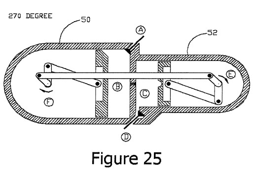
FIG. 25 illustrates a DPCE dual cylinder configuration
having supercharge capabilities, in accordance with one
embodiment of the invention. As shown in FIG. 25, the
compression cylinder portion 50 is larger than the power
cylinder portion 52, therefore allowing a greater volume of
air/fuel mixture to be received and compressed in the
compression chamber B. At the completion of the compression
stroke, the larger volume and increased pressure of
compressed air/fuel mixture (i.e., "supercharged" fuel
mixture) in the compression chamber B is injected into the
combustion chamber C via interstage valve 12. Therefore, a
greater amount and/or higher pressure of fuel mixture can be
injected into the combustion chamber C of power cylinder 52
to provide a bigger explosion and, hence, more energy and
work, during the power stroke.
As mentioned above, FIG. 26 illustrates an alternative DPCE
dual cylinder configuration, in accordance with one
embodiment of the invention, wherein the compression
cylinder 60 is offset from the power cylinder 62, to provide
minimal thermal conductivity between the two cylinders. In
this embodiment, the interstage valve 12 is located in the
small area of overlap between the two cylinders.
FIG. 27 illustrates a DPCE dual cylinder configuration in
which both cylinders are constructed parallel to each other
and both pistons are moving in a tandem manner, in
accordance with a further embodiment of the invention. In
this embodiment, the intake, exhaust, and interstage valves
may operate in the same manner as described above. However,
as shown in FIG. 27, the interstage valve is located in a
lateral conduit that couples the first and second cylinders.
In an alternative embodiment according to the invention, a
steam enhanced double piston cycle engine (SE-DPCE) is
configured to use excess heat in the combustion chamber to
convert added water into steam to increase engine efficiency
and output. Like the DPCE described above, separating the
compression stroke location from the power stroke location
enables the development of significantly higher combustion
chamber temperature. In this embodiment, the DPCE described
above is extended to additionally comprise a unique
ring-shaped steam cylinder that is located between the
combustion chamber and the exhaust passage. The SE-DPCE
utilizes concentrated heat residing in areas located between
the combustion chamber and the internal surface of an
exhaust tube shell, which is wrapped around the combustion
piston cylinder.
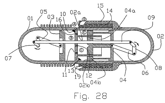
FIG. 28, in accordance with one embodiment of the invention,
illustrates a cross-sectional view of a SE-DPCE that
includes many similar features described above: a
compression cylinder 01, a power cylinder 02, a compression
piston 03, a power piston 04, two respective piston
connecting rods 05 and 06, a compression crankshaft 07, a
power crankshaft 08, a crankshaft connecting rod 09, an
intake valve 10, a combustion exhaust valve 11, and part of
an interstage valve 12. The compression cylinder 01 is a
piston engine cylinder that houses the compression piston
03, the intake valve 10 and an interstage valve 12. The
power cylinder 02 is a piston engine cylinder that houses
the power piston 04, the exhaust valve 11, and part of the
interstage valve 12. The power cylinder 02 further comprises
an inner cylinder 02a and an outer cylinder 02b. The power
piston 04 further comprises a dual-head piston further
comprising a disc-shaped inner piston 04a and a ring-shaped
outer piston 04b. The power cylinder 02 also includes: a
compressed air valve 16 located within the outer power
cylinder 02b and extending to the compression cylinder 01, a
steam/air exhaust valve 13 located within the outer power
cylinder 02b, an outer exhaust shell comprising a wrapped
exhaust pipe 14, and a heat isolation layer 15. In one
embodiment, the power cylinders 02, 02a and 02b are
manufactured using highly conductive materials for further
heat energy utilization.
In one preferred embodiment, the compression piston 03
serves for the intake and the compression engine strokes.
The inner power piston 04a serves for the fuel combustion
power and the exhaust (burned gaseous) strokes. The outer
power piston 04b produces additional power and at the same
time serves to cool chamber c and power piston 04a by the
absorption of engine excessive heat, utilizing hot
compressed air with or without steam/water. The connecting
rods 05 and 06 connect the compression piston 03 and both
power pistons 04a and 04b to their respective crankshafts 07
and 08. The compression crankshaft 07 converts rotational
movement into compression piston 03 reciprocating movement.
The power crankshaft 08 converts inner and outer power
pistons 04a and 04b reciprocating movement into engine
rotational output movement. The crankshaft connecting rod 09
transfers the power crankshaft 08 rotation into compression
crankshaft 07 rotation. The engine intake valve 10 is
composed of a shaft having a conic shaped sealing surface,
the same as is used in most four stroke engines. The exhaust
valve 11 is composed of a shaft having a conic shaped
sealing surface, that same as is used in most four stroke
engines. The interstage valve 12 is composed of a shaft
having a conic shaped sealing surface.
FIG. 29 illustrates a cross-sectional, perspective view of
the power cylinder 02: a spark plug 22 located within the
inner cylinder 02a, a fuel injection nozzle 20 located
within the inner cylinder 02a, and a water/steam injection
nozzle/valve 21 located in the outer cylinder 02b. In
further embodiments, the SE-DPCE apparatus can additionally
utilize electrical starters, pressurized oil lubrication
systems, controlled water/steam systems to control water
quantity, pressure and temperature, well-known high voltage
timing and spark plug electrical systems, and output shaft
flywheels. A combustion exhaust valve 11 includes a shaft
having a conic shaped sealing surface, same as in most four
stroke engines. When open, the valve 11 enables burned hot
gaseous to exit the combustion chamber and stream into the
exhaust wrapped shell 14. An interstage valve 12 is composed
of a shaft having a conic shaped sealing surface. When open
the interstage valve 12 enables compressed charge (fuel air
mixture) to be pushed from the compression chamber into the
combustion chamber. The steam/water outlet valve 13 is
configured to open and close mechanically. When open the
valve 13 enables the expanded steam water mixture to be
pushed out by power piston 4b and be exhaled from the
secondary power chamber E back into a supply water
closed-loop system (not shown) or totally out of the engine
The power cylinder 02 further includes a compressed air
connecting valve 16, which is also configured to open and
close mechanically. When open the valve 16 enables
compressed hot air to be pushed from the engine compression
chamber into the secondary power chamber E. A thermal
isolation layer 15 is an external thermal isolation shield
that prevents heat energy escape. By utilizing this shield
15 most of the engine excessive heat is forced to stay
within the engine inner structure and thus to be converted
by the secondary power chamber E into additional useful
work. A fuel injection nozzle 20 is a mechanically operated
valve that includes a fuel spray nozzle. In one embodiment,
a direct pressurized fuel injection system, operated through
predetermined engine cycle time band, pushes fuel into the
combustion chamber. Using this system is an alternative to a
common carburetor fuel supply system in which the fuel is
sprayed in advance into either, the engine incoming air
supply or during the engine compression stroke.
The power cylinder 02 further includes a water injection
valve 21 configured to open and close mechanically and
further including a water spraying nozzle. A pressurized
water injection system, operated through a predetermined
engine cycle time band, pushes water into the secondary
power chamber E. The water is vaporized into compressed hot
steam and thus produces elevated pressures and at the same
time cooling cylinder 2a. A spark plug 22 is used to
initiate fuel air compressed mixture explosions. Finally,
FIG. 29 illustrates a cross-sectional view of an exhaust
passage 23 that is wrapped around the secondary power
cylinder perimeter in order to maintain and provide
additional heat to the power cylinder.
Referring again to FIG. 28, when both the compression piston
03 and the power pistons 04 are at their TDC positions, the
available volume in chamber B of cylinder 01 is minimized.
At TDC, cylinder 02a and 02b also have minimized volumes in
their respective contained chambers C and E. In one
embodiment, the power crankshaft 08 rotates clockwise and
causes the connecting rod 09 to move and rotate the
compression crankshaft 07 clockwise. The rotation of
crankshafts 07 and 08 actuates both pistons 03 and 04 to
perform a symmetrical synchronous reciprocating movement in
which the compression piston 03 and the power piston 04
moves inboard and outboard symmetrically in an equally paced
manner. In alternative embodiments according to the present
invention, a phase lag or phase advance between the relative
location of the compression piston 03 and either the inner
power piston 04a or outer power piston 04b, or both, may be
introduced.
In one embodiment according to the present invention, the
SE-DPCE cycle begins as compression piston passes through
its TDC and the intake valve 10 opens. Ambient air flows
into compression cylinder 01 chamber B. The compression
crankshaft 07 rotates and the compression piston 03 moves
until it reaches BDC, at which point the intake valve 10
closes. The compression piston 03 then performs its
reciprocal movement back toward TDC causing the air pressure
and temperature within chamber B to increase. At various
predetermined points, one or both of the interstage valve 12
and the connecting valve 16 open. The connecting valve 16
allows compressed air to be pushed from the relatively high
pressure chamber B into the then lower pressure combustion
chamber C and into the ring shaped air/water/steam chamber
E. In one embodiment, the compressed air is substantially
transferred to the power cylinder 02 when the compression
piston 03 and power piston 04 reach their TDC. Around the
time the compressed air is finished being transferred to the
power cylinder 02, the interstage valve 12 and compressed
air valve 16 close. Fuel is injected into chamber C through
fuel injection nozzle 20 and temperature-controlled water is
sprayed and/or injected into chamber E via a water injection
valve 21 (FIG. 29), respectively. The temperature-controlled
water may be added into chamber E before, during, or after
the valves 12 and 16 have finished closing. Spark plug 22
(FIG. 29) fires, causing combustion to occur, which
forcefully pushes the inner power piston 04a toward its BDC.
Simultaneously, the injected water and compressed air within
chamber E expand and evaporate into steam which in turn
dramatically increases pressure in chamber E. This increased
pressure forcefully pushes the outer power piston 04b toward
BDC. During the water to steam conversion (phase change),
the engine excessive heat produced during combustion in
chamber C is efficiently and productively removed to chamber
E.
The SE-DPCE cycle ends as power piston 04 begins moving back
towards TDC. At the same time, the exhaust valve 11 opens,
the high temperature combustion products are directed from
exhaust valve 11 into a port 19 and then pushed within a
pipe wrapped around the outer cylinder 02b and exhaled out
through area D, thereby heating the cylinder 02b. At or near
the same time the exhaust valve 11 opens, the steam outlet
valve 13 opens and the previously extract products (steam,
water, air) of chamber E are recycled into the supply water
close-loop system. In one embodiment, the steam outlet valve
13 opens and the previously extracted products (e.g., steam,
water, air) of chamber E are drained or expelled out of the
engine without recycling any water or steam for further
energy generation. In alternative embodiments, in order to
save energy, water and/or steam is recycled and the recycled
liquids in chamber E can be used to pre-heat the incoming
injected water. Before power piston 04 reaches TDC, the
exhaust valve 11 and steam outlet valve 13 close again. A
new cycle begins as the compression piston 03 retreats
toward its BDC, and the intake valve 10 re-opens. In one
embodiment, the external power cylinder 02 outer
circumference is covered by a thermal isolation material
layer 15, in order to minimize SE-DPCE heat energy losses.
In one embodiment, as shown in FIG. 30, piston 04 includes a
hot section 30, which is adjacent to and/or in direct
contact with the combustion product and hotter cylinder
surfaces. The hot section 30 is made out of temperature
resistance materials like carbon or ceramic. This piston
section carries only longitudinal forces. A secondary
sliding disk 36 receives most of the sliding side friction
forces. Section 30 is the hot part of piston 04, and it is
cooled and lubricated utilizing a small amount of water and
steam leakages. Section 32 is the colder part of piston 04
and it is further cooled and lubricated utilizing well known
piston engine lubrication methods. A disk 38 separates the
oil lubricated colder section 32 from the hotter piston
steam lubricated section 30. A power connecting rod 06
connects a piston ear 34 to the power crankshaft 08.
FIG. 31 illustrates construction and lubrication of the
power piston 04 in accordance with one aspect of the present
invention. In one embodiment, the power cylinder 02 and
pistons 04, 04a and 04b surfaces that are directly engaged
with the combustion process are enforced with ceramic. The
ceramic surfaces of the power cylinder 02 and pistons 04,
04a, and 04b are water/steam cooled and lubricated. As the
outer power piston 04b approaches BDC a small amount of
steam is released through nozzles into the area in between
the power piston 04 and inner and outer power pistons 04a
and 04b. The hot piston portion side forces are absorbed by
an additional piston sliding disc 36, which carries most of
the piston side stresses and is oil-lubricated using
well-known methods. The piston sliding disc 36 separates and
seals the area around the crankshaft 08 from the rest of the
area within the power cylinder 02. Thus, by utilizing
innovative cooling and lubrication aspects of the present
invention, the SE-DPCE can operate under higher
temperatures.
The oil separation disc 36 takes most of piston 04 side
sliding friction forces, during engine crankshafts rotation,
machine oil is allowed to flow toward cylinder surface 48
(between cylinder 02 and piston 04). In one embodiment,
engine common seal rings 42 may be installed around the
perimeter of disc 36. Piston and cylinder sliding surfaces
46 and 50 utilize water and steam as cooling and lubrication
liquids, those substance are than drained out of cylinder 02
through drain port 44.
FIG. 32 illustrates another embodiment according to the
present invention wherein the SE-DPCE comprises a split
compression piston 03. The compression piston 03 is divided
into an inner compression piston 03a and an outer
compression piston 03b. The inner compression piston 03a
sucks ambient air, with or without carbureted fuel, through
an intake valve 54 and compresses it through the interstage
valve 12 into the combustion chamber C. The outer
compression piston 03b that sucks ambient air through an
intake valve 10 and compresses it through a connecting
intake valve 16 into air-steam chamber E. In one embodiment,
water is also added into the intake air chamber F and then
compressed through connecting intake valve 16 into chamber
E, or alternatively, water can be injected directly into
chamber E via water injection nozzle 21 (FIG. 29). A split
compression piston configuration enables the engine to make
use of carbureted fuel that is sucked into chamber G. In
addition, the split compression piston and chamber
configuration enables the SE-DPCE to be designed such that
the total incoming air is volumetric divided between
chambers F and G and the volume of each chamber F and G can
be independently determined.
FIG. 33 illustrates another embodiment according to the
present invention wherein the SE-DPCE comprises two separate
power producers in which a primary combustion system
utilizes the fuel-air combustion process, while a secondary
water-steam-air system utilizes excess engine heat. In this
embodiment, the primary combustion system comprises a
compression piston 03a, a power piston 04a, an intake valve
54, an exhaust valve 11, an interstage valve 12 and an
output shaft 08. In one embodiment, the exhaust from exhaust
valve 11 is input into the cylinder heating port 19 to heat
cylinder 02b, as described above. The secondary
water-steam-air system comprises a compression piston 03b, a
power piston 04b, an intake valve 10, an interstage valve
16, a steam/air exhaust valve 13 and a secondary power
output shaft 60. The primary combustion system converts fuel
and air into engine work as describe above. The secondary
water-steam-air system in one embodiment utilizes
substantially identical piston reciprocal movement,
connecting rod motion and crankshaft rotation to the primary
combustion system. However, in the secondary water-steam-air
system, heated air, water, and/or steam can be used to
produce engine work. Each power producing system actuates
its own operating valves. The primary combustion system
actuates valves 54, 12 and 11, as well as an optional fuel
injection system in one embodiment. In this embodiment, the
secondary system actuates valves 16 and 13 and optionally
the water chamber E direct injection system (nozzle 24, FIG.
29). In accordance with the discussions above, in some
embodiments, the primary compression piston 03a and primary
power piston 04a are configured to operate with a phase
difference such that they reach their TDC positions at
different times. Similarly, the secondary compression piston
03b and secondary power piston 04b can also be configured to
operate with a phase difference with respect to one another.
In one embodiment, the SE-DPCE makes use of the following
dynamic parts, which serve the secondary power output (the
compression and power pistons movements which utilizes
engine heat for additional engine power output). The
secondary power output includes two pistons, comprising a
ring compression piston 03b and a ring output piston 04b,
two compression connecting rods 70, a compression crankshaft
68, a power crankshaft 60, a power crankshaft connecting
rods 64 and crankshaft connecting rod 66. The connecting
rods connect respective pistons to their respective
crankshafts. The compression crankshaft 68 converts
rotational movement into reciprocating movement of the
compression ring piston 03b. The output power crankshaft 60
converts output power ring piston 04b reciprocating movement
into secondary output 60 rotational movement. The crankshaft
connecting rod 66 transfers the output power crankshaft 60
rotation using crankshaft 62 into compression crankshaft 68
rotation.
In one embodiment, there is no engine internal engagement
between the primary and secondary shafts 08 and 60. In this
embodiment, each system is independent, with the power and
speed of each shaft depending on engine working condition
and engine input parameters. In an additional embodiment,
the SE-DPCE is capable of accepting a carbureted fuel/air
charge as well as performing a fuel injection method of
combustion. And, in yet another embodiment, the SE-DPCE is
capable of accepting air and water as well as air followed
by injected water directly sprayed into chamber E. In
another embodiment according to the present invention, the
SE-DPCE utilizes an electronic optimization management
computer (not shown) which monitors engine temperature, RPM,
engine torque, fuel consumption, injected water temperature,
and injected water quantity. The computer analyzes these
various engine physical parameters accordingly adjusts the
injected water quantities, temperatures and injected fuel
quantities for best performance.
In various other embodiments according to the present
invention, the SE-DPCE may have any of several additional
features. In one embodiment, the water-steam chamber E
operates with water and/or steam instead of compressed air.
As piston reaches TDC, water and/or steam are injected into
chamber E. Combustion piston 03 transfers compressed air
only through interstage valve 12 into chamber C. The water
cooling and work producing functions describe above are
performed with injected water into chamber E and the
accompanying phase change into steam. During piston
retraction, as the piston moves toward TDC, chamber E steam
and/or water is exhaled through the steam/air exhaust valve
13. In an additional embodiment, the steam may be heated to
a higher temperature for better engine performance.
In another alternative embodiment either water and/or steam
may be replaced with another liquid or gas such as Ammonia,
Freon, Ethanol or any other suitable expandable liquids
(include gaseous).
In a further embodiment, compressed air alone, and not water
or steam, is injected into chamber E.
In another embodiment, a boiler layer 71 comprises a
plurality of passages 71 for holding fluids and/or gases
therein, wherein the boiler layer 71 is wrapped around at
least a portion of the combustion chamber housing 02. As
shown in FIG. 34, in one embodiment, the boiler
layer/passages 71 are surrounded by the passages 14 of the
wrapped exhaust pipe 14, both of which are surrounded by
heat isolation/insulation layer 15. It is understood that
the cross-sectional views of passages 71 and 14 are
illustrated as square and circular shapes, respectively. for
purposes of illustration only. In actual implementations,
any desired shape may be utilized for these passages. In
alternative embodiments the passages 71 and/or passages 14
may each be configured as a single larger passage or channel
for holding fluids and/or gases therein that is wrapped
around the combustion chamber housing. In one embodiments,
pressurized water or other suitable fluid from an external
source (not shown) is pushed by a hydraulic pump (not shown)
into the boiler passages 71 via an inlet port 72. Since
combustion chamber C, cylinder 02 and the inner wrapped
exhaust layer 14 temperature are very high, any water (or
any other liquid) flowing or injected into the inlet port 72
will rapidly turn into high pressure steam. In one
embodiment, the high pressure steam is then directed from
steam output port 74 toward an external steam piston engine
(not shown) or steam turbine (not shown), which converts the
steam energy into additional useful mechanical work, such as
turning an electrical generator or mechanically engaging the
SE-DPCE main output shaft 08. The isolation layer 15 keeps
most of SE-DPCE heat energy within the engine structure. As
power piston 04 begins its exhaust stroke hot combustion
gases flows through exhaust valve 11 into inlet exhaust wrap
port 19, thereby heating the inner wrapped exhaust layer 14.
After transferring part of their heat energy into the
water/steam wrap tube 14, the exhaust gases are exhaled from
the engine through output port D.
By implementing the above-described method and apparatus,
the SE-DPCE embodiment creates and utilizes steam energy by
using previously unused thermal energy. The generated steam
energy is then used to produce additional mechanical work.
In one embodiment, the steam energy is utilized by an
auxiliary steam engine or steam turbine, which then converts
the steam energy to additional work.