Thomas Townsend BROWN
Electro-Gravity Device
Office of Naval Research File 24-185 (15 September 1952)
An Investigation Relative to T. T. Brown
by Willoughby M. Cady (ONR, Pasadena)
1 ) Introduction
This report summarizes a technical investigation of certain claims of Thomas Townsend Brown concerning a proposed method of propulsion for aerial vehicles. The investigation, which began May 3, 1952 and which is concluded hereby, is mainly analytical, no allotment having been made for an experimental program.
2 ) Brief Description of the Alleged Phenomena
Mr. Brown claims to have discovered several new physical effects, and considers them to be interrelated. We will be concerned here with those relating to the force upon and between electrically charged bodies in air or under oil.
2.1 ) It is asserted that the force exerted upon a negatively charged body by a positively charged body is greater than the force exerted upon the latter by the former; that the force differential is proportional to the mass of the dielectric inserted between the bodies; and that the phenomenon is evidence of a new "electrogravitic" effect. Paragraph 4 contains a fuller description of these phenomena.
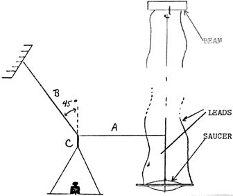
2.2 ) A corollary effect is the force tending to move a metallic disc which by means of a plastic disc supports a fine wire, AA tangentially disposed in its plane, as shown in Figure 1. When the wire is positively charged (e.g., 30 kilovolts) and the disc negatively charged, a propulsion force of a fraction of an ounce appears which moves the disc (and with it the wire) in the direction of the arrow C. These effects have been witnessed by the writer. Further discussion is presented below in paragraph 6.
Figure 1: Demonstration Flying Saucer

2.3 ) An apparatus has been examined superficially, which shows an unexpected torque on an oil-immersed disc when charged. This, according to Mr. Brown, is arranged to record automatically and frequently the magnitude of the angular deflection of the disc. These records have been tabulated and partially analyzed by Mr. Brown. Greater detail regarding this device is given in paragraph 5 below.
2.4 ) There has been briefly inspected a third electrical device, purporting to be a communication equipment operating on waves related to the electrogravitic effect. It appears that the transmitter is simply a relaxation oscillator consisting of a high tension DC power supply, a high resistor, and a condenser which periodically discharges through a short gap. The receiver, shown in Figure 2, consists of two Pyranol capacitors 0-5 mf, two titanium oxide capacitors 500 mf, a Brush recorder, and a bypass capacitor 0.1 mf to prevent the recorder from oscillating. Two terminals in the circuit are charged as indicated before reception and left floating during reception. The bridge of four capacitors is housed in a cabinet, indicated by a dashed line, which forms an obviously imperfect shield against electromagnetic radiation. When the transmitter is operated in an adjoining room, the Brush recorder jumps with each spark. Mr. Brown states that the effect is present, but reduced, if the 25 kv potentials are not applied. If the Pyranols are short-circuited and removed, the effect is still reported present. No attempt has been made at conscious electromagnetic shielding of either the transmitter or the receiver. In the writer's opinion the response may be the result of a chance rectifying contact.
The relation between the communication device and the mechanical effects which form the topic of this report appears to remote that no further mention will be made of the former.
Figure 2: Electro-Gravitic Communication Device

3 ) The Investigative Method
This study is limited to the technical claims of Mr. Brown and is not concerned with matters of personality or personnel, or with the Townsend Brown Foundation. Although propulsion is the immediate center of interest, the claimed basic effect and its several manifestations are of the essence also. Therefore the analysis is not restricted to the propulsion apparatus.
Rough quantitative data have been taken by the writer on the force between charged bodies, and on the force on the disc shown in Figure 1. He has also carried out a brief examination of the recorded data on the oil-immersed disc. Whenever possible, word-of-mouth data have been ignored. It is regrettable that during the time of the investigation the greater part of the experimental data gathered over the years by Mr. Brown are unavailable, being in storage elsewhere.
Full reliance is placed on the sincerity of Mr. Brown in his written reports of the data, but no reliance is placed on his interpretations. His orally reported data have been partially discounted as being less reliable than his written records. There is no evidence of conscious deceit.
Most of the interviews have taken place at the Townsend Brown Foundation, 306 North Vermont Avenue, Hollywood, California.
4 ) The Basic Effect
At Zanesville, Ohio in 1927, Mr. Brown at this then Laboratory of Research Devices, performed experiments on force acting upon charged conductors. The apparatus took two forms, as described in a manuscript "Tapping Cosmic Energy", dated 28 October 1927, which was submitted at that time to the Physical Review for publication but which was rejected. Apparently no basic experiments have been performed since 1928.
4.1 ) In one form the conductors were two independent spheres suspended close but not touching by means of fine wires which also served as electrical leads. The spheres were of lead, and weighed 14,740 gr each. The wires supporting them hung from the ceiling 45 cm apart. When the spheres were oppositely charged to a potential difference of 125 kv they moved toward each other slightly in response to their electrostatic attraction. The negative sphere was displaced allegedly about twice as far as the positive sphere. The inequality of the displacement is the essence of the phenomenon.
4.2 ) In the other form of the basic experiments the condenser was formed by a block of insulating material 3-1/3 c 2-1/2 x 15", to the ends of which electrodes were attached. Whether the condenser was suspended or whether it was mounted at the end of a centrally pivoted horizontal beam, it showed a force causing the arm to rotate, usually in such a direction that the positive electrode moved forward. The force is claimed to have been proportional to the mass of the block, although no data are given in the manuscript and none are available. The name "gravitor" is used for this apparatus.
The condenser dielectric was either homogenous or laminated. In one laminated version, 10,000 sheets of 0.001" lead foil were separated by an equal number of 3 x 3" sheets of 0.0008" cellulose acetate in a formica box, to make 10,000 condensers in a series arrangement weighing 10 kg. The acceleration exhibited by this device when suitably charged is claimed to have been 2.5 cm per sec2 when the electrodes were charged, evidencing a force of 25,000 dynes or about 25 gm; the homogenous type is stated by Mr. Brown to have had comparable thrust. The force was usually toward the positive electrode, although in some units it was toward the negative; this effect was attributed to a "polarization". The force is stated to have been stronger at some time that others, correlating with the position of the sun and moon. Data are displayed which relate to the angular speed of a pivoted gravitor, and which show half a dozen large fluctuation in a day; some of these can perhaps be construed a being dips simultaneous with the rise or setting of the sun or moon.
On 17 June 1952 the undersigned accompanied (censored) of the Townsend Brown Foundation to the Glendale plant of the Bendix Aviation Corporation. An experiment of the type described in paragraph 4.1 had been set up by Bendix personnel. (Sentence censored). The observations in Table 1 were recorded by the undersigned.
Table 1: Observations by the Writer on 17 June 1952 Experiment at Bendix Aviation Corp., Glendale, CA

From a wooden scaffold a cylindrical brass weight 8" long and 4" in diameter was hung with axis vertical by means of about 5' of #14 Cu wire (0.06408" diameter). A similar wire about 6" away suspended a similar weight level with the first. By means of the wires the weights were electrified to a measured voltage; the corona current was not measured. An optical projection system provided on the wall an image on a scale and insulated pointers attached to the weights. The weights were either hollow (5 lb) or solid (30 lb). In certain of the observations the weights were linked by an insulating bar.
4.3 ) An examination of the data makes it clear that the inequality in deflections reported by Brown is still present here, though only to the extent of 1-30% (tests 2-4) and less than that under conditions where the corona discharge is reduced (of tests 1 & 5).
When cigarette smoke was drifted into the vicinity of the wires it showed the existence of a wind. Just above the weights the wind blew from negative top positive, while higher on the wires the wind was opposite.
5 ) The Brown Electrometer
In a small thermostated room in the second basement of the Banks-Huntley Building (address censored), Los Angeles, there is a continuous experiment which shows an extension of the basic phenomenon. This apparatus is the Brown Electrometer. The device is housed in an oil-filled tank of half-inch steel, perhaps two feet in diameter and a foot deep, with a half-inch steel cover. In the tank there is suspended a horizontal disc 12" in diameter and one inch thick, made of six segments of pine wood alternating with six of marble around an 8" hub of Bakelite. The sections are separated by 1 x 2 x 1/16-inch copper strips. Alternate strips are grounded to a central metal stem supporting the disc which is attached to a music-wire suspension 0.018" in diameter and 6-3/8" long; the remaining copper strips connect to a central iron tit at the center of the hub, which dips into a cup of mercury. The disc is surrounded by a grounded metal shield which is attached to the tank and which stands at a clearance of 1/2-inch above and below the disc and 1-1/2 inch radially; this shield is centrally perforated at the top and bottom for the suspension and the tit.
A sequencing device in a cabinet below the tank causes a half-wave smoothed DC power supply to impress upon the mercury cup a well-regulated negative potential of 11.1 kv resulting in a leakage current of 0.45 ma. The sequencer leaves the voltage on for 30 seconds, causing the disc to rotate several degrees. After 30 seconds, a short spark is made to jump from a point projecting about 9 inches horizontally in air from the stem of the disc, and perforates a rice-paper strip wound on a drum which rotates once each day. The voltage is then turned off and the disc returns to its relaxed position, which is recorded by a separate spark. The cycle repeats every three minutes. The apparatus appears to be well engineered and extremely reliable.
5.1 ) Mr. Brown has given attention for several years to the variations in the deflections of this electrometer. On the spark record the rest position is 50 units and the deflected reading is about 80. Until about a year and a half ago the deflected position was about 20, but suffered a gradual change to its present value at that time. Aside from the reversal of sign, the deflection undergoes fluctuations whose character is less dramatic but still large, e.g., 10-50%. The cause of these fluctuations has been sought by Mr. Brown by seeking for correlations between them and various outside influences, such as magnetic storms, temperature, pressure, the time of the year, civil time, lunar time, sidereal time, and the Dow-Jones average. Only the last five correlations are claimed. Tabulated data are available only for the year 1937. Hourly recordings throughout that year are tabulated, both for civil and lunar time. The writer has seen no convincing evidence that the stock market and the automatic recorder are correlated, although it has been claimed that a chi-square analysis has been performed, with positive results.
5.2 ) The undersigned has conducted a partial statistical analysis of the data from the automatic recorder for 1937 as follows:
5.2.1 ) Use was made of a table furnished by Mr. Brown entitled "Hourly Readings of Instrument, 1937" and particular attention was directed toward the readings of 0100, one hour after midnight, on each day of the first half of 1937. During the first half of January, for instance, the readings on days at this hour were 26.20, 25.90, 26.20, 26.10, 26.80, 25.60, 25.40, 26.00, 26.00, 25.60, 26.60 and 25.90. The mean is 26.05, the standard deviation 0.55 and the probable error of the mean 0.15. Table 2 gives the half-monthly means and probable errors for time 0100 and for time 1300. This table shows that there was a strong and real variation during the spring of 1937; but the great similarity between the readings at 0100 and 1300 implies that there is no conspicuous diurnal effect. (See also paragraph 5.2.2)
5.2.2 ) A direct search was undertaken by the writer to see whether the data for the first half of 1937 reveal any solar diurnal period. Attention was confined to the first day in each half-month. On these twelve selected days the readings at time 0200, for example, were 26.20, 26.00, 27.90, 29.00, 28.10, 29.80, 30.40, 29.80, 28.90, 27.50, 27.40, and 28.10. The mean was 28.29 and the probable error of the mean 0.46. The probable errors, as far as calculated, were all in this neighborhood. Table 3 gives the means calculated as in the above example. It is seen that there is no strong diurnal periodicity, with the dubious exception of a peak at 1100 hours; this result confirms that of paragraph 5.2.1.
5.2.3 ) The undersigned has scrutinized a table of data captioned "1937 Readings of Instrument with Lunar Hour Angle" in a search for evidence of a variation of the readings with the position of the moon, as rising, setting, etc. The form taken by this search was as follows. For the calendar month January the average deflection for each lunar hour was noted; e.g., at lunar hour angle 1300, when the moon was one hour past the meridian, the readings for January averaged 26.74. At the same lunar angle in the succeeding calendar months the average readings were 28,60, 30.18, 29.50, 28.02, and 28.52. The average of those six averages gives 28.59 as the mean of all observations taken at lunar hour angle 1300 during the first half of 1937. This process was repeated for each of the 24 hours. The means are listed in table 4. Their constance is most striking; they show no dependence upon lunar hour.
Table 2: Half-month mean deflections at two times a day, during the first half of 1937

Table 3: Hourly deflections averaged over the first day of the half-month in January-June 1937. The Probable errors are above 0.46

Table 4: The deflection of the instrument as averaged over the first half of 1937 for each lunar hour angle

5.3 ) By the foregoing sketchy analysis of the data from the Brown Electrometer, the following conclusion are implied:
(a) Through the
weeks and months the data drift significantly;
(b) There is no evidence of a solar diurnal period
synchronizing with the sun, as claimed by Brown;
(c) There is no evidence of a lunar diurnal period
synchronizing with the moon, as claimed by Brown. On the
contrary, the data appear most emphatically to deny such a
period.
5.4 ) Two related experiments have been described by Mr. Brown which throw light on the reason for the deflections if not the reason for their fluctuations.
5.4.1 ) In one, the sector disc was held stationary while a grounded metal disc was suspended horizontally over it in the oil, by a torsion fiber. When the sector disc was charged, a motion of the adjacent oil was noted by Mr. Brown. The suspended disc deflected, but not when a glass plate was interposed between the sector disc and the suspended disc.
5.4.2. ) The other related experiment concerns an oil-immersed annulus described by Mr. Brown as 2 feet in diameter and 6 inches thick, made of lead oxide (PbO) and paraffin in eight segments separated by 8 copper strips alternately charged positive and negative. By means of a probe the potential distribution on the PbO and paraffin surfaces was explored and it was noted that whereas the gradient was uniform across the edges of the lead oxide sectors, the gradient on the paraffin was steepest near the negative electrodes. This observation means that the steepest gradients are all in the same direction, e.g., clockwise. It was also noted that the application of high voltage to the electrodes of this disc caused a lively motion of the oil.
6 ) The Model Flying Saucers
At the quarters of the Townsend Brown Foundation a room is devoted to demonstrating a new method of propulsion (para. 2.2) which is claimed to depend upon the electrogravitic effect.
6.1 ) At the center of the room there stands a tall iron post carrying at its top a transverse Plexiglass beam about 6 feet long, which is freely pivoted at its center to rotate in a horizontal plane. From each end of the beam hangs a model flying saucer, Figure 1, of which the metal part is composed of two spun aluminum discs 12" in diameter, between which is bolted an 18" Plexiglass disc. The periphery of this disc is indented with nearly semi-circular scallops. The fingers remaining between the scallops constitute standoff insulators supporting a bare 0.005-inch stainless steel wire AA at a distance of 3 inches from the aluminum spinnings and insulate it from the aluminum. This will be called the outboard wire in the following discussions. It embraces perhaps one-quarter of the circumference. A similar wire, BB, is supported at the opposite quadrant, but is connected to the aluminum spinnings; it appears to be without effect. Each of these two identical assemblies is suspended by an insulating string from one end of the Plexiglass beam. By rubber-covered leads, shown in Figure 3, from the beam spinnings can be given one polarity while the outboard wires are given the opposite polarity. The leads are energized through rotating contacts at the pivot. If the beam rotates counter-clockwise as seen from above, the discs revolve about the post, in such a way that the outboard wire is at the leading edge.
A full-wave rectified unsmoothed high-tension supply in an adjacent room provides voltage for the demonstration. The voltage is controlled by a Variac. An examination showed no hidden connections.
6.2 ) When the power was turned on, the discs became negative and the outboard wires positive. Corona discharge could be heard as a gentle hiss or crackling. It could be seen in the dark, particularly around the outboard wire. As soon as the potential was applied, the discs and the beam began to revolve, the leading edge being at the outboard wires.
6.2.1 ) The thrust was roughly measured by a method in which the rotation was prevented, as shown in Figure 3. The weight on the pan was adjusted until the indicated angle was 45 degrees, at which time the thrust was known to be equal to the force in the vertical thread. This method of thrust measurement is valid if the pivot is frictionless; actually, the friction seems to introduce an uncertainty of about 0.5 gm in the thrust data. The procedure described provides a value of the thrust of the two discs combined.
Figure 3: The method involving three threads A, B & C as used to measure the thrust of a demonstration flying saucer
6.2.2 ) The data shown in Table 5 were gathered by the writer on 6 June with the collaboration of Mr. Brown and (censored), an assistant. Column 1 gives the setting of the Variac in the supply circuit for the high-tension transformers. The corresponding voltages, with respect to ground at the positive and negative outpost cables from the rectifier are given in columns 2 & 3; at each polarity the voltage was measured with the aid of a 0-2 milliameter and a high series resistor. The current in each lead, recorded in Columns 4 & 5, was measured by the same milliameter when appropriately reconnected; it may be resumed that most of the current represented corona discharge between the discs and the outboard wires. Column 6 gives the measured thrust. In Column 7 is recorded the time taken for the discs to revolve once completely when free to do so, after they had had time to reach their full speed. The entires in Column 8 give the thrust to be expected on the basis that it is caused by the electric wind (see para. 7 below). The last Column shows the efficiency of the propulsion, calculated (with due heed to the conversion of units) from the ratio of the electrical power input (Col. 2 x Col. 4 plus Col. 3 x Col. 5) to the mechanical power output (Col. 6 x Velocity). The data in Columns 2 & 3 were gathered first, then those in Columns 4, 5 & 6, and finally in Columns 2 & 3 again. The repeat measurements of the voltages nearly always agreed with the first measurements to within 0.75 kv or less. The average is recorded in Columns 2 & 3.
Table 5: The results of measurements on the demonstration apparatus for flying saucers

6.2.3 ) Three additional observations were made. In one, slips of thin cardboard were cut, folded double and so hung on the outboard wire of each disc as to cover practically its entire length. Their purpose was to confine the positive ions to the region of the wire and so reduce the corona. It was observed that the thrust, originally about 7 gr as shown in Table 5, was reduced to about 1 gr.
6.2.4 ) In the second additional observation the polarity of the discs was made positive while the wire was negative. The thrust was then 3 / 1 gr (in the same direction as before) instead of about 7, the Variac setting being 40, 45 and 50.
6.2.5 ) The third additional observation was that when the disc was charged and immobilized as in Figure 2, a brisk wind was developed. The origin of the wind was apparently near the outboard wire. Its direction was from the wire toward and past the aluminum spinning as shown by cigarette smoke.
7 ) Possible Theories of the Townsend Brown Phenomena
7.1 ) Mr. Brown has no theory for the effects that he has demonstrated or claimed. He has advanced an empirical explanation for the magnitude of the force on a suspended condenser, but has not advanced supporting evidence. While granting the existence of the electric wind, Mr. Brown seems nevertheless to believe that some new force is operating which he describes as electrogravitic. This force is variable with time as shown by the Brown Electrometer. The origin of the force is of smaller interest to Mr. Brown than is the cause of its variations. No cause for the variations has been proposed, other than the alleged correlations with astronomical bodies.
7.2 ) It might be suggested that electrostriction is significant in Mr. Brown's effects. This suggestion is untenable because (1) the deflection of a suspended condenser (Table A [sic], Tests 6 & 7) is far greater than any conceivable electrostrictive expansion or contraction; (2) electrostriction would cause no acceleration of the center of the center (sic) of gravity; and (3) the steady rotation of the flying saucer models cannot be caused by electrostriction, which is a dynamic effect only while the voltage is changing, and not in the steady state.
7.3 ) The force exerted upon a wire carrying a current in a magnetic field could conceivably contribute to the phenomenon. This hypothesis appears tenable at first sight, since the earth always provides the field, and with the corona discharge there is always associated a current. It is easily disproved, however, by (1) the sign of the deflections shown in Table 1 was unchanged in test 3 when the polarity, and thereby the direction of any magnetic effect, was reversed; (2) the direction of the thrust by the model flying saucer was unchanged by changed polarity; (3) the equal and opposite corona currents in the leads to the saucers should result in equal and opposite magnetic force, and zero net thrust; and (4) there is no report that the Brown Electrometer shows normal deflections during magnetic storms.
7.4 ) The writer proposes that the origin of the observed phenomena is the electric wind. The effects described above all relate to the forces upon electrically charged bodies or upon adjacent insulating material. Such forces have long been the subject of observation and mathematical theory, and are discussed accordingly in such works as W.R. Smythe's "Static and Dynamic Electricity". It is commonly held by physicists that no practical discrepancies exist between theory and experiment in static electricity, if the experiments are conducted in the manner contemplated in the theory. It must be emphasized in this connection that the theory of electrostatics is written around the assumption that the insulators in the apparatus are perfect non-conductors, and that the fluid (e.g., air or oil) in which the apparatus is immersed is also a perfect non-conductor. For an experiment performed in a non-conducting medium the verdict of electrostatics is quite plain: the Townsend Brown effects should not exist.
The experiments by Mr. Brown, including all those described in paras. 4, 5 and 6 were carried out in a partially conducting medium, i.e., air or oil. In such a medium the simple laws of electrostatics are not applicable. It is true that in the air or oil the conduction of electricity is usually so slight that the departures from the laws of electrostatics are quite negligible. When, however, large voltage gradients are involved, the density of ions is very greatly increased for well-known reasons, and the conductivity of the medium increases commensurately. If the voltage is high enough the passage of the ions through the air causes the crackling sound and bluish glow characteristic of the corona discharge. In the presence of such a discharge, the laws of electrostatics are not expected to hold. We will show that, so far from being forbidden, the Townsend Brown effects are actually predicted in the presence of a corona discharge.
7.5 ) We will adapt the treatment cited in (name censored) ("Conduction of Electricity Through Gases, 3rd ed., Vol. II, 1933, page 544) in considering the force on a charged conductor brought about by the ionic conductivity in a gas. Consider a positively charged fine wire in air, parallel to a negative conductor. The well known concentration of the electric field near the fine wire will then produce a corona discharge; positive ions are generated at the wire. The wire being positively charged repels the ions. The force on the wire is roughly equal and opposite to that on the ions. If E is the field intensity and u the space charge density, the force on the ion is:
![]()
Where the integration covers the region occupied by the space charge. Here if we ignore the non-parallelism of the E vectors, we may write roughly
![]()
It is known that the velocity W of an ion in a fluid is related to the electric field in which it moves through the relation
W = kE
Where K is ionic mobility.
For a positive ion in air at atmospheric pressure its value will be taken as 1.32 (cm/sec)/(volt/cm), while for the negative ion the value will be taken as 2.51 (cm/sec)/(volt/cm).
since
is the current,

Where d is the distance between the conductors. This force on the ions is communicated to the air by molecular collisions, and creates what is known as the electric wind; it is observed in the neighborhood of sharp points as well as fine wires. The thrust may be regarded as the force of reaction which results from the generation of the wind; the thrust is in the direction opposite to the wind, as in a jet airplane.
7.5.1 ) It is known that the mobility of a negative ion is greater than that of a positive, the ratio being about 1.9 at atmospheric pressure. The force on a positive conductor should therefore be, and according to (censored) and (censored) is observed to be, greater than that on a negative conductor.
7.5.2 ) Further confirmation of the above theory is found in the variation of F with pressure. Theory predicts that since k is well known to vary as the inverse square of the pressure the force should vary directly as the square root of the pressure; this prediction agrees with the early results of Arrhenius, Wied. Ann. 63: 305 (1897).
7.5.3 ) The efficiency of the electric wind as a propulsive agent is easily calculated. The power output is the product ViD/k of the thrust and the vehicle velocity V; while the power input is iv is the potential difference. The efficiency is then given by

At a given vehicle velocity the efficiency can be improved by increasing the electrode spacing D or by decreasing the voltage necessary to sustain the corona.
7.6 ) Physically the theory of the electric wind is a shown in Figure 4, which shows a section view of two parallel charged wires in air. Positive ions are formed at the positive wire and surround it, but the attraction of the negative wire draws the positive cloud so that it lies primarily to the left of the positive wire in Figure 4. The slow mobility of the positive leads to a considerable positive charge in this region, which is repelled by the positive wire and which repels it. Negative ions are generated at the negative wire, and form an unsymmetrical cloud about it. Since their mobility is fairly fast, they are less crowded than the positives. The force on the positive wire is made of two parts; attraction to the left by the negative cloud (e.g., 20 gr) and repulsion to the left by the ion cloud (e.g., 10 gr). the force on the negative wire is: attraction to the right by the positive wire (e.g., 20 gr) and repulsion to the left by the ion cloud (e.g., 5 gr). The net force on the positive wire would in this hypothetical case be 10 gr to the left, while that on the negative wire would be 15 gr to the right. The difference, 5 gr to the right would be directly observed if the weights hanging from the wires were connected by a rigid insulating link.
Figure 4: The ion clouds near two parallel oppositely charged wires in air

8 ) Test of the Electronic Wind Hypothesis
It is believed by the writer that the electric wind in air and in oil leads to all the well-documented results described herein. These results will be summarized and compared with the theoretical predictions.
8.1 ) (See para. 4.1) The positively charged sphere in the Zanesville experiments moved less that the negatively charged weight. This is as expected because the electrostatic force on the positive weight was partly balanced by the kinetic reaction from the electric wind which presumable existed (para. 7.5 & 7.6) because of the corona discharge at the wires.
8.2 ) (See para. 4.3) The inequality in the motion of the weights in the Bendix experiment was less noticeable, thus discouraging corona and reducing the current. The observed electric wind was caused by corona at the wires, which was more or less strong according as the wires were rough or dusty in different areas.
8.3 ) (See para. 4.2) the deflection of a suspended condenser when charged was claimed. This is as expected if the leads or terminals sustain a corona. The "polarization" effect would seem to be evidence that one or the other lead or terminal had rough areas, sharp corners, or dust resulting in corona at one end to the other, and a thrust in one or the other direction. If the terminals have the same geometry, the force will, because of the lesser mobility of the positive ions, be directed toward the positive terminal; if the negative terminal is much rougher or sharper, it will be the seat of a corona of which the force might outweigh that at the positive terminal. The observed fluctuations in the effect are to be expected as the result of changing dust on the wires or terminals, which changes the corona current; the deflections in the Bendix experiment were somewhat irregular.
8.4 ) (See para. 5) The disc of the Brown Electrometer shown in Figure 5 develops a torque in response to an applied voltage. The field in the oil is strongest in the regions A.B.V.D. where the oil is in contact with the electrodes separating the pine sectors from the marble sectors M. Positive ions formed at the electrodes as in a corona discharge will produce positive space charges at the regions A. & D. while regions B. & C. will have negative space charges. In the oil these will cause effects analogous to the electric wind in air. If the fields A.B.C.D. are equally strong the ion densities will be such as to give no net torque to the disc. We will assume, on the other hand, that the surface of the pine sectors allows a leakage current; this will have the effect of reducing the field in the regions A. & B. and will leave the regions C. & D. dominant in the production of force. The positive ions at D. will tend to rotate the disc clockwise while the negatives will tend to rotate is counterclockwise. Since their mobilities differ there will be a net torque in one or the other direction, as observed. If the chemistry of the oil or the insulating sectors changes with time the surface conductivity of the marble could become larger than that of the pine, causing a reversal of the torque. Aside from surface conductivity, other attributes may distinguish the marble from the pine. For example, a net torque might be caused by the influence of different dielectric constants from the field distribution, or if alternate sectors all project slightly from the electrodes.

Figure 5: Electrometer
A net torque might result from or be influenced by the surface conductivity of the pine and marble. If one is more conductive than the other, the field pattern will be made unsymmetrical (See para. 5.4.2) and the torque will be altered. It is possible that the slow fluctuations in the Brown Electrometer are caused by changes in the surfaces. The faster fluctuations may be caused by particles suspended in the oil, which may temporarily rest at such points as A. or B., changing the corona there temporarily.
8.5 ) The experiment reported in para. 5.4.1 would seem to corroborate the idea that a swirling of the oil is essential to the operation of the electrometer. This idea is in accord with the electric wind theory, whether or not the discussion in para. 8.4 is valid in detail.
8.6 ) It is claimed that the deflections of the electrometer show certain periodicities. If these are real they show the inadequacy of the electric wind hypothesis. Their reality is assessed in the crude and preliminary analysis contained in para. 5.2 and summarized in para. 5.3. There is no manifest solar diurnal period and no manifest lunar diurnal period. No test has been applied for the claimed sidereal diurnal period or for the correlation with the value of financial securities. Neither has it been possible to determine whether the slow changes in deflection (Table 2) are repeated annually as claimed; however, the fact that the deflections once annually permanently reversed direction would seem to discourage this claim. This reversal is attributable to changed surface conductivity of the sectors of the disc. It is concluded that the short study, para. 5 of the reading of the Brown Electrometer does not weaken the hypothesis that all the (censored: probably reads, "phenomena reported by Mr. Brown") are the result of electric wind.
8.7 ) The thrust observed in the experiment on the model flying saucers is given in Table 5, para 6.2.2. The thrust to be expected on the electric wind hypothesis is tabulated as calculated from the equations, para. 7.5. This agreement is satisfactory in order of magnitude. Actually the calculated thrust is about twice the observed. The discrepancy may be due to the approximations made in the mathematics of para. 7.5.
8.8 ) (See para 6.2.3) A partial shielding of the insulated wire on a model flying disc partially eliminated the thrust, presumable because the current was probably thereby reduced. The shielding also had the effect of making the approximations in para.7.5 still worse. Qualitatively, then, the electric wind hypothesis is again verified.
8.8 ) (See para. 6.2.4) With polarity reversed so that the insulating wire was negative, the thrust fell form about 7.5 gr to about 3 gr, the ratio being 2.5. Unfortunately the current was not measured. Assuming it to have been unchanged in magnitude by the reversal, we would predict, from the result, that the mobility of the negative ions is 2.5 times greater than that of the positives. This is in fair agreement with the known factor of 1.9.
8.10 ) (See para. 6.2.5) A wind was observed to be generated near the outboard wire of the model flying saucers. This is as expected on the hypothesis under evaluation. The thrust experienced by the disc may be regarded as the jet reaction caused by the formation of this wind.
9 ) Conclusion
9.1 ) All the well documented effects disclosed by Mr. Brown appear to be explained as caused by ionization of the air or oil in which the apparatus is immersed.
9.2 ) Mr. Brown claims that a gravitational anomaly exists in the neighborhood of a charged condenser. This effect has not been well documented by Mr. Brown, nor has the writer undertaken to refute it.
9.3 ) The thrust developed by the model flying saucers has its origin in the well-known phenomenon of the electric wind.
9.4 ) The efficiency of propulsion by the electric wind, as exemplified by the model flying saucers is of the order of 1.4 percent. At speeds higher than 2.3 ft/sec attained by the model flying saucer the efficiency might be substantially improved. It is presumable less at high altitudes and zero in a vacuum.* If the efficiency of conversion of fuel energy into electrical energy is 21 percent the overall efficiency of propulsion of the model flying saucers by the electric wind is 0.3 percent. This compares with about 25 percent for a propeller-driven airplane and about 15 percent for a jet airplane.
End of Report
Classification of this report cancelled by authority of Office of Naval Research Ltr. 2340, by Capt. Dewey Brown, CI Div., Dir., Special Investigations, HQ USAF, Wash. DC., 1 October 1952.
* N.B.: The "presumably less at high altitudes and zero in vacuum" hypothesis was later disproven by Brown during experiments in France, where it was shown that in fact the efficiency of his model flying saucers actually increased when flown in high vacuum. ~ Ed.
N.B.: The remainder of the report is comprised of miscellaneous military letters that do not contain any pertinent information. ~ Ed.