Rene
Nunez Suarez
Turbostove
Turbostove
95%
Efficient, burns any fuel
http://www.keelynet.com/indexnov1107.htm [ 11/30/07 ]
http://www.thedailygreen.com/green-homes/eco-friendly/cooking-stove-invention-461129
Eco-Friendly
Cooking Stove Invention
Rene Nunez Suarez of San Salvador has spent years in a passionate, single-minded quest to provide the world's poor with a high-efficiency stove, in an effort to fight global warming and reduce deforestation. Now, the acclaimed inventor is left with praise, but no money and an estranged family, as reported by the Los Angeles Times. The device clearly has noble aims.
It's a stainless-steel cooker that uses about 95% less fuel than conventional wood stoves, with minimal pollution.
In El Salvador, millions still cook their daily meals with wood, and the countryside has long been denuded of so many of its invaluable trees. Worldwide, about half the planet cooks and heats with inefficient, polluting traditional fuels, according to the World Resources Institute.
That means millions suffer from asthma, cancer and other problems associated with inhaling so much particle pollution. In fact, cooking fire pollution has been blamed for the deaths of an estimated 1.6 million people a year worldwide, mostly women and children.
Plus, hours are often spent each day gathering and preparing firewood, dung and other fuels. That's time not spent in school or on other more economically productive activities.
Nunez has secured a U.S. patent and a prestigious award from the Paris-based International Energy Agency for his Turbococina, or Turbostove.
What Nunez has long sought is funding to get the stoves distributed to those who need them in the countryside. But so far he hasn't secured interest from investors he says he can trust or nonprofit organizations.
Nunez's sad story isn't unfamiliar in a world fraught with inequality. Many observers have long complained that the technology may exist to provide better drugs for malaria, dysentery and possibly even AIDS, but that lack of the ability of those who need them most to pay means little incentive for capitalistic systems.
Sometimes there seems like an orgy of R&D and marketing spending on the latest gadgets, hair-loss remedies or shiny, sexy toys, while a brilliant inventor with a relatively simple device to help save the world can't get any notice.
PATENTS
DEVICE
FOR GENERATING AND TRANSMITTING HEAT CAPABLE OF OPERATING
WITH FUEL IN ANY PHYSICAL STATE AND COMBUSTION FLAME.
MX2011003817
US2011239916
WO2010042079
MX2011003817
US2011239916
WO2010042079
Device for generating and transmitting heat capable of operating with fuel in any physical state that includes at least one cylindrical combustion chamber (9) divided into a lower section (11) and an upper section (12) of variable height, a pressurized air chamber (26) arranged below the lower section (11) of the combustion chamber, and a plurality of air injectors (14). The device is characterized in that the air injectors (14) are supported on a flat ring (43) and set in a second flat ring (52) and in that it also includes a set of replaceable parts (A) arranged in the free centre of both flat rings (43 and 52) and whose specific configuration depends on the physical state of the fuel being used. Furthermore said set of replaceable parts (A) includes at least one central air injector (16) located in the geometric centre of the unit.
OBJECT OF THE INVENTION
[0001] The present invention, as the present specification states in its title, is intended to provide a device for generating and transmitting heat capable of operating with fuel in any physical state, i.e. it can be fed with fuel in solid, liquid or gas state. In turn, it is an object of the invention to maximize the combustion efficiency, i.e. that the fuel consumption is intended to be optimized, which results in significant fuel savings and the reduction of the emissions of pollutants.
[0002] Likewise, the present invention is Intended to describe a combustion flame generated inside the described device for generating and transmitting heat, flame whose properties are highly advantageous in terms of heat transfer and for preventing the production of pollutants.
TECHNICAL FIELD OF THE INVENTION
[0003] The present invention falls within the methods for obtaining energy through combustion processes, within the heat transfer processes and their generator and transmitter devices. It has general application within the field of combustion and heat transfer, for both industrial applications and domestic use.
[0004] Among the concrete and practical applications of the present invention, its use in the field of steam generation for heating or electric power generation can be mentioned.
[0005] Also among non-industrial applications of the invention its use in heaters, stoves, ovens, kitchens and the like can be mentioned.
STATE OF THE ART PRIOR TO THE INVENTION
[0006] Currently there are lots of devices for generating and transmitting heat, combustion chambers of which are intended to obtain combustion as "perfect" or "complete" as possible, in order to achieve savings in fuel consumption, while seeking to minimize the generation pollutants.
[0007] As the background closer to the present invention, it is known the U.S. Patent 6,651,645 BI that describes a device for generating heat for solid fuel. Although said document explicitly states that the described apparatus can be used "for other types of fuels such as powder fuels, liquid fuels or gas fuels", the practice shows that it is not possible to use any of the solutions described in said patent with liquid or gas fuels. Among the solutions described in said document, none of them describes or suggests a device that can be used with liquid or gas fuel, and is not mentioned, nor suggested that the same apparatus admits fuels in any physical state (solid, liquid or gas).
[0008] Additionally, the device for generating heat described in US6,651,645-B1 has some drawbacks, such as the fact that due to the high temperatures reached inside the combustion chamber, the substantially parallel plates or discs wherein the air injectors are embedded, are bent; which can lead to their breakage.
[0009] Therefore, it was desirable to obtain a device for generating and transmitting heat that:
can be used with fuels in any physical state, whether solid, liquid or gas, while
manages to maximize the combustion efficiency so as to obtain significant fuel savings,
manages to transfer the maximum amount of produced heat to the place of its utilization, i.e. minimizing heat losses into the environment.
prevents the emission of pollutants such as nitrogen oxides (NOx), and
be resistant to high temperatures generated inside the combustion chamber.
DESCRIPTION OF THE INVENTION
[0010] The present invention is intended to provide a device for generating and transmitting heat, capable of operating with fuel in any physical state, i.e. fuel in solid, liquid or gas state, which in turn allows to achieve the desired objectives and overcome the drawbacks of heat generators existing in the prior art.
[0011] Thus, the new device for generating and transmitting heat, object of the present invention comprises at least one combustion chamber preferably with a tubular shape, preferably constituted by a cylinder. Said cylinder is preferably divided into two sections, a lower section and an upper section of variable height. The height may be varied depending on the density of heat per volume unit of the combustion flame to be obtained in the combustion chamber. Furthermore, the apparatus of the present invention comprises a pressurized air chamber disposed below the lower section of the cylinder that forms the combustion chamber, and a plurality of air injectors.
[0012] The air injectors are supported on a first flat ring that forms the upper part of the pressurized air chamber and set in a second flat ring arranged in contact with the lower end of the cylinder that forms the combustion chamber. These air injectors are preferably arranged following the circular path of the flat rings, in a substantially radial direction from the center to the outside. The fact of providing the air injectors supported on the first flat ring instead of setting thereof in a disc or plate provides the following advantages:
the air injectors can slide on the first flat ring, so that when high temperatures generated inside the combustion chamber and the resulting expansion that said ring may suffer, the presence of the injectors does not cause its bent and possible breakage, and
inside the flat rings, i.e. in the central or free area, a set of replaceable parts can be provided, configuration of which is defined by the physical state of the fuel to be used, whether solid, liquid or gas.
[0013] The second flat ring is fastened by fixation means preferably of the type of a pin, bolt or screw arranged to be sandwiched between the air injectors.
[0014] The number of injectors is in principle not relevant and depends on the diameter of the cylinder that forms the combustion chamber. However, as the aim to achieve with this particular arrangement of air injectors is a rotational flow from the injection of the different air flows, thus the minimum number of injectors required to obtain said rotational flow is the one that, according to the diameter of the cylinder that forms the combustion chamber, and the arrangement described, resembles a circle. Thus, for example, it can be indicated that from 6 air injectors, i.e. forming a hexagon, the configuration starts resembling a circle. It is also preferable to have an even number of injectors in order to ensure that the flame resulting from the combustion remains equidistant from all points of the cylinder that forms the combustion chamber.
[0015] Thus, as noted above, the apparatus of the present invention comprises a set of replaceable parts, arranged in the free center of the flat rings, in the lower end of the lower section of the cylinder that forms the combustion chamber and attached to the second flat ring through an expansion joint, and configuration of which is defined by the physical state of the fuel to be used.
[0016] Finally, the apparatus of the present invention comprises at least one fan or set of fans arranged below the pressurized air chamber In order to provide air to the pressurized air chamber itself. A preferred embodiment of the fan or set of fans also provides the existence of a sliding sheet placed for closing or opening the space of air intake to the fan or set of fans in order to regulate the air intake.
[0017] Additional description of the cylinder that forms the combustion chamber:
[0018] In a preferred embodiment, the two sections of the cylinder that forms the combustion chamber are formed by the interposition of a third flat splitter ring. It will also be allowable embodiments in which the two sections of the cylinder are formed from, for example, a cave or narrowing in the walls of the cylinder itself, adopting for example a form similar to that of an "hourglass."
[0019] In a preferred embodiment, on the walls of the upper section of the cylinder that forms the combustion chamber, pressure relief holes are provided.
[0020] In the preferred embodiment, in addition, the cylinder that forms the combustion chamber is complemented with a thermal insulation system consisting of a series of concentric cylinders, separated by spaces through which air circulates.
Description of the pressurized air chamber:
[0021] The pressurized air chamber comprises a second cylinder arranged concentrically and below the lower section of the combustion chamber and diameter of which will preferably be the same or higher than that of the combustion chamber.
[0022] In the preferred embodiment, the diameter of the second cylinder that forms the pressurized air chamber is higher than that of the cylinder that forms the combustion chamber, so as to coincide with a fourth concentric cylinder that is part of the thermal insulation system, as explained later herein.
[0023] The pressurized air chamber provides pressurized air to the plurality of air injectors supported on the first flat ring and to the central air injector, included within the set of replaceable parts.
[0024] The upper part of the pressurized air chamber makes up the first flat ring, on which the air injectors are supported.
[0025] The first flat ring comprises, in turn, a vertical skirt support, the top of which is preferably finished in a crown shape.
[0026] Description of the air injectors:
Each air injector has
a side aperture and
an upper aperture.
[0027] The side aperture allows injecting air flows in a substantially horizontal direction, i.e., air used for combustion. The upper aperture allows injecting air flows in a substantially vertical direction, i.e. air having dual functionality, combustion and cooling.
[0028] Furthermore, the central air injector, included within the set of replaceable parts, has only one upper aperture that allows injecting air flow in a substantially vertical direction. This air flow in a substantially vertical direction feeds the center of the combustion chamber, i.e. injects the air directly used for combustion.
[0029] In this way it is ensured that the combined action of different air flows into the combustion chamber produces a rotational air flow.
[0030] The inclusion of the central air injector makes the central air flow to have the strength required for feeding the center of the flame, since it is not just one hole through which air enters as may go in, but an injection of pressurized air.
[0031] In a preferred embodiment, each air injector has in its side aperture, a nozzle for the exit of air. The nozzles serve to improve the routing of air flows into the combustion chamber.
Description of the structure of the set of replaceable parts:
[0032] The configuration of the set of replaceable parts depend on the physical state of the fuel to be used, whether solid, liquid or gas, but in any case includes a central air injector arranged in the geometric center of the unit and set between two flat and parallel discs that are part of said set.
[0033] Thus, in all cases, in addition to comprise the central air injector, the set of replaceable parts comprise a flat disc attached to the second flat ring through an expansion joint, and a second flat disc supported on the first flat ring; such that the central air Injector is set between both discs, in its geometric center.
[0034] Furthermore, in the geometric center of the second flat disc, around and concentric with the central air injector, a plurality of apertures through which pressurized air enters from the pressurized air chamber is provided, such that the air that enters through said apertures contributes, when impact against the first flat disk, to its cooling. Moreover, and due to the finishing in a crown shape of the top of the vertical skirt support, the incoming air follows a substantially horizontal path until exiting the outside through the recesses of the crown shape of the vertical skirt support. Thus, the function of this air flow in a substantially horizontal direction will be the one for cooling.
[0035] For gas or liquid fuels, the set of replaceable parts further comprises:
a plurality of fuel injectors supported on the second flat disc and set in the first flat disc, distributed preferably following the circular path of the discs,
a fuel distributor, arranged bellow the fuel injectors and upper part of which forms the second flat disc, and
a fuel supply tube that feeds the fuel distributor.
[0036] The fuel injectors preferably have a side aperture so that the injection of gas or liquid fuel is performed following a substantially horizontal direction so as to contribute to the rotational direction of air flows.
[0037] In addition, the fuel injectors are preferably fed through their bottom because the fuel distributor is arranged below the same.
[0038] When the fuel to be used is liquid, placing of a collector plate for retaining the liquid is further forecasted, and the configuration of the fuel distributor is modified, such that the fuel supply performs a substantially horizontal path and parallel to the first flat disc before the fuel reaches the fuel injector.
[0039] The use of the collector plate for retaining the liquid is not indispensable, but it is suitable for the case of using fuel in a liquid state.
[0040] In a preferred embodiment, the device for generating and transmitting heat, regardless the physical state of the fuel to be supplied carries a thermal insulation system. Said system consists of a series of cylinders concentric with the cylinder that forms the combustion chamber, and it will be explained in detail in the "embodiment of the invention" section.
[0041] Materials: The materials for the various component elements of the combustion chamber are preferably metals and among these the use of stainless steel is preferred. Also in the preferred embodiment the interior walls of the combustion chamber are preferably reflective and with a shiny silver color, so as to optimize the radiation return of the heat from the cylinder walls to inside. The more reflective it is, the greater will be the return and the lower will be the heat loss.
[0042] It should be mentioned that, although the heat sink is not an integral part of the apparatus of the present invention, it is preferable that it be placed above the combustion chamber leaving an air space in the middle.
[0043] The air in the upper part of the combustion chamber will be used as heat insulation, when the air is in a horizontal direction, or as a heat transmitter, when the air is in the vertical direction.
[0044] It is also noteworthy that the embodiments described for liquid or gas fuel could also be used for solid fuels, for example in cases of solid fuels with difficult ignition. Thus, the combustion with a gas or liquid fuel could be started, and then pass it to the solid fuel. In these cases, the fuel injectors (gas or liquid) will include, in addition, a cover. Or alternatively, the injectors of fuels in liquid or gas state are lowered until being leveled with the first flat disc.
Description of the combustion flame:
[0045] Finally, within the device for generating and transmitting heat described by the present invention a combustion flame with geometrical shape and technical characteristics advantageous in terms of fuel efficiency and emission of pollutants is generated.
[0046] Thus, it is also an object of the present invention said combustion flame formed by a plurality of combustion discs formed, in turn, by combustion gases, with the combustion discs being separated from each other by means of air discs formed by the air flows supplied for oxidizing the fuel when the air supply is made such that the combined action of air flows produces a rotational air flow as the one described in the combustion chamber of the apparatus of the present invention.
[0047] Said rotational air flow provides the flame the form of a pulsating vortex, and can have central air areas and sections of continuity between the combustion gas discs. Additionally, combustion discs acquire some upward vertical speed within the combustion chamber, and since as an increased speed of the combustion discs a less heat transfer to the medium is produced, thus depending on the upward vertical speed of the combustion discs and the thickness thereof, the heat transfer (or loss) to medium will be more or less. It will be less, as thinner the combustion discs are, and as higher upward vertical speed is imparted thereto.
[0048] Additionally, at the upper end of the combustion flame one or more terminations in a more or less elongated shape can be formed.
[0049] Thus, this new geometrical shape of the combustion flame achieves considerably increasing the combustion flame surface, i.e. the oxidation surface, or area wherein the air oxygen comes in contact with the combustion flame. Furthermore, with this shape of combustion flame the air supplied for oxidizing the fuel is at very short distances from any area inside the combustion flame and therefore the fuel efficiency is maximized.
[0050] It has also been demonstrated that the thinner the combustion discs that make up the combustion flame are, the greater is the oxidation surface of the combustion flame.
BRIEF DESCRIPTION OF THE FIGURES
[0051] The present invention will be fully understood on the basis of the brief description below and the accompanying drawings which are presented only by way of example and, thus, do not restrict the present Invention and wherein:
Figure 1 shows a scheme of a complete longitudinal section of the apparatus for generating and transmitting heat capable of operating with fuel in any physical state object of the present invention, wherein the set of replaceable parts (A) for fuel in a gas state or fuel in a liquid state has been represented, but without the retaining plate;
Figure 2 shows a scheme of a longitudinal section of the device for generating and transmitting heat capable of operating with fuel in any physical state of the previous figure, wherein the set of replaceable parts (A) has been schematically represented, the thermal insulation system has been removed and the bottom area of the pressurized air chamber (26) has been cut in order to allow a greater detail in the rest of the apparatus;
Figures 3a, 3b and 3c respectively show a perspective view of the set of replaceable parts (A) for the case of solid fuel, gas fuel (or liquid without retaining plate (53)) and liquid fuel with retaining plate (53)
Figure 4 shows a perspective view of the pressurized air chamber (26);
Figure 5 shows a side view of the pressurized air chamber (26);
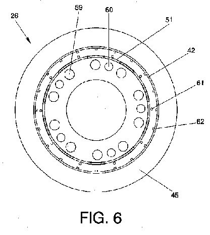
Figure 6 shows a top view of the pressurized air chamber (26);
Figures 7a, 7b and 7c respectively show a top view of the pressurized air chamber (26) with the set of replaceable parts (A) of Figures 3a, 3b and 3c respectively;
Figure 8 shows a scheme of a longitudinal section of the device for generating and transmitting heat capable of operating with a fuel in any physical state of the previous figure, wherein the bottom area of the pressurized air chamber (26) has been cut in order to allow greater detail for the rest of the apparatus, and wherein the set of replaceable parts (A), shown in Figure 3b, for using gas or liquid fuel without retaining plate (53) has been represented;
Figure 9 shows a scheme of a longitudinal section similar to that of Figure 8, but wherein the set of replaceable parts (A), described in Figure 3c, for using liquid fuel with retaining plate (53) has been represented;
Figure 10 shows a scheme of a longitudinal section similar to that Figure 8, but wherein the set of replaceable parts (A), described in Figure 3a, for using solid fuel has been represented;
Figure 11 shows a sectional view of section A-A of Figure 9;
Figure 12 shows a scheme of a longitudinal section of a specific embodiment that only includes the possibility of using gas or liquid fuels, without the retaining plate of the apparatus of the present invention, wherein the bottom area of the pressurized air chamber (26) has been cut In order to allow greater detail for the rest of the apparatus;
Figure 13 shows a scheme of a longitudinal section similar to that of Figure 12, but for a specific embodiment that includes only the use of solid fuels;
Figure 14 shows a sectional view of section A-A of Figure 12;
Figure 15 shows an enlarged view of Figure 14 so as to better see the movement of air flows; and the injection of liquid or gas fuel; the references of a particular injector are numbered, but it is understood that each injector has associated an air a fuel injector,
Figure 16 shows an alternative embodiment of Figure 15, wherein 14 air injectors (14) instead of 10 air injectors as in Figure 15 are arranged;
Figure 17 shows a scheme of a longitudinal section for an alternative embodiment of Figure 13, and in which detail an alternative embodiment of the described knob (56), and which is to perform a bent (57) on the walls of concentric cylinders;
Figure 18 shows a sectional view of section A-A of Figure 13;
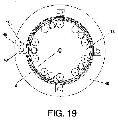
Figure 19 shows a sectional view of section A-A of Figure 17;
Figure 20 shows another sectional view of section A-A of Figure 12, but with the retaining plate (53):
Figure 21 shows a top view of the hot air flows that the heat sink (41) in the top of the device for generating and transmitting heat will receive;
Figure 22 shows a scheme of, at least one, fan (63);
Figure 23 shows a scheme of the sliding sheet (55), and
Figure 24 shows a scheme of a combustion flame obtained within the combustion chamber of the present invention.


[0052] These figures contain numerical references associated with the following elements:
A: set of replaceable parts
2: air flows in a substantially horizontal direction emerging from the air injectors
3: combustion discs of the combustion flame
4: air discs of the combustion flame
5: injection of gas or liquid fuel
6: central air area of the combustion flame
7: sections of continuity of the combustion flame
8: combustion flame terminations
9: first cylinder, which forms the combustion chamber
10: third flat ring, splitting the two sections of the combustion chamber
11: lower section of the cylinder that forms the combustion chamber
12: upper section of the cylinder that forms the combustion chamber
13: first flat disc
13': flat disc for specific embodiments wherein the apparatus only admits fuel in a physical state, defined at the time of its construction
14: air injectors
14a: side aperture of the air Injectors
14b: upper aperture of the air injectors
15: air flows in a substantially vertical direction emerging from the air injectors
16: central air injector
16': plurality of apertures around the central injector air
17: air flow in a substantially vertical emerging direction from the central air injector
18: pressurized air coming from the pressurized air chamber
19: fuel injectors
20: supply of liquid or gas fuel
20': substantially horizontal path for the liquid fuel supply
21: pressure relief holes of the cylinder that forms the combustion chamber
22: third cylinder, concentric with the cylinder that forms the combustion chamber
23: separation space between the cylinder that forms the combustion chamber and the third cylinder
24: air flow circulating through the lower end of the separation space (23) between the cylinder that forms the combustion chamber and the third cylinder, i.e. the space defined between the vertical skirt support (51) that forms the pressurized air chamber (26) and the third cylinder (22)
25: pressure relief holes of the third cylinder
26: pressurized air chamber
27: pressure relief holes of the fourth cylinder
28: fourth cylinder, concentric with the previous ones (9 and 22)
29: fuel supply pipe
30: fuel distributor
31: air flow in a substantially horizontal direction emerging from the recesses forming the crown of the vertical skirt support
32: air flow circulating through the separation apace between the cylinder that forms the combustion chamber and the third cylinder
33: outlet or upper end of the separation space between the cylinder that forms the combustion chamber and the third cylinder
34: separation space between the third and fourth cylinder
35: air flow circulating through the separation space between the third and fourth cylinder
36: outlet or upper end of the separation space between the third and fourth cylinder
37: fourth flat ring of the upper edge of the third cylinder
38: fifth flat ring of the upper edge of the fourth cylinder
39: ring that has at its outer edge the fifth flat ring of the upper edge of the fourth cylinder
40: separation space between the apparatus for generating and transmitting heat and a heat sink
41: heat sink
42: second cylinder that forms the pressurized air pressure chamber
43: first flat ring on which the air injectors are supported
43': flat disc for specific embodiments wherein the apparatus only admits fuel in a physical state, defined at the time of its construction
44: second flat disc of the fuel distributor
45: sixth flat ring on which the lower end of outer cylinder, concentric with the cylinder that forms the combustion chamber, is supported
46: fixation means
47: air nozzle
48: fasteners
49: pins
50: bolt
51: vertical skirt support finished in a crown shape
52: second flat ring in contact with the lower end of the cylinder that forms the combustion chamber
53: retaining plate for liquid fuel
54: expansion joint or slot
55: sliding sheet
56: knob
57: bent
58: support for heat sink
59: holes for allowing the air supply to the air injectors
60: holes for fixing the second flat ring (52)
61: hole for feeding air into the separation space (23) the cylinder (9) that forms the combustion chamber and the third cylinder (22)
62: hole for feeding air into the separation space (34) the third and fourth cylinder (22 and 28)
63: fan for pressurizing the air in the pressurized air chamber (26).
EMBODIMENT OF THE INVENTION
[0053] In order to obtain a better understanding of the object and functionality of this patent, and without being construed as restrictive solutions.
[0054] Figure 2 shows a general scheme of a device for generating and transmitting heat capable of operating with fuel in any physical state that includes:
one cylindrical combustion chamber (9) divided into two sections, one lower section (11) and one upper section (12), the height of the lower section being preferably lower than that of the upper section;
one pressurized air chamber (26) preferably constituted by a second cylinder (42), diameter of which is preferably equal to that of the cylinder that forms the combustion chamber (9) and arranged below the lower section (11) of the combustion chamber,
a plurality of air injectors (14) that have a side aperture (14a) and an upper aperture (14b) and which are supported on a first flat ring (43) that forms the upper part of the pressurized air chamber (26) and set in a second flat ring (52), arranged in contact with the lower end of the first cylinder (9) that forms the combustion chamber,
a set of replaceable parts (A) arranged on the free center of both rings (43 and 52), and
at least one fan, not shown in Figure 2, since the bottom area of the pressurized air chamber (26) has been removed in order to allow greater detail for the rest of the apparatus.
Figure 1, as mentioned above, shows a complete scheme of the apparatus of the present invention, wherein the set of replaceable parts (A), for the case of using gas fuel or liquid fuel has been represented, but without the retaining plate. Thus, it shows an apparatus comprising:
one cylindrical combustion chamber (9) divided into two sections, one lower (11) and one upper (12) section,
one pressurized air chamber (26) constituted by a second cylinder (42), diameter of which is greater than the cylinder that forms the combustion chamber (9) and arranged below the lower section (11) of the combustion chamber,
a plurality of air injectors (14) that have a side aperture (14a) and an upper aperture (14b), and which are supported on a first flat ring (43) that forms the upper part of the pressurized air chamber (26) and set in a second flat ring (52), arranged in contact with the lower end of the first cylinder (9) that forms the combustion chamber,
a set of pieces, which happens to be the set of replaceable parts (A) of Figure 2 for the case of fuel in a gas or liquid state without retaining plate. Said set of pieces is arranged in the free center of both rings (43 and 52), at the lower end of the lower section (11) and consists of:
a first flat disc (13),
a second flat disc (44),
a central air injector (16),
a plurality of fuel injectors (19),
a fuel distributor (30),
a fuel supply tube (29) of the fuel distributor (30), and
a plurality of apertures (16'), around the central air injector (16)such that the first flat disc (13) is attached to the second flat ring (52) by an expansion joint (54): the second flat disc (44) forms the upper part of the fuel distributor (30) and is supported on the first flat ring (43) and parallel to the first flat disc (13); the fuel injectors (19) are arranged on the second flat disc (44) and passed through their corresponding holes in the first flat disc (13); the fuel distributor (30) is arranged below the fuel injectors (19); the central air injector is set between both flat discs (13 and 44), in the geometric center thereof; the plurality of apertures (16') is arranged in a circular distribution on the second flat disc (44) and around the central air injector (16). The fuel supply tube (29) although it is preferably located on a side of the fuel distributor (30) may admit any location that allows the entry of fuel in the fuel distributor (30). In addition, the holes in the first flat disc (13) through which the fuel injectors (19) pass have a diameter slightly larger than the diameter of the fuel Injectors (19) so as to allow the expansion of the flat disk (13) caused by high temperatures generated inside the combustion chamber.
[0055] Furthermore, in Figure 1 at least one fan (63) located below the lower area of the pressurized air chamber (26) is represented.
[0056] Figure 1 also represents some arrows indicating the direction of the air flows. Thus, the pressurized air chamber (26) provides pressurized air (18) to the plurality of air injectors (14) and to the central air injector (16). Each air injector (14) has a side aperture (14a) and an upper aperture (14b), so that the side aperture (14a) allows injecting air flows in a substantially horizontal direction (2) into the lower section (11) of the combustion chamber. The upper aperture (14b) allows, in turn, injecting air flows in a substantially vertical direction (15) into the lower section (11) of the combustion chamber. And, the central air injector (16) injects an air flow in a substantially vertical direction (17) into the lower section (11) of the combustion chamber. In this way it ensures that the combined action of all air flows (2, 15 and 17) produces an upward rotational air flow In the lower section (11) of the cylinder (9) that forms the combustion chamber.
[0057] Being the scheme in Figure 1 a preferred embodiment, it also considers the presence of pressure relief holes (21) in the walls of the upper section (12) of the cylinder (9) that forms the combustion chamber.
[0058] Also, by being a preferred embodiment, the third flat ring (10), splitting the two sections (11 and 12) of the cylinder (9) that forms the combustion chamber, is represented.
[0059] In addition, and for being a preferred embodiment, the thermal insulation system is represented, which consists of:
a third cylinder (22), concentric with the first cylinder (9) making up the combustion chamber, said third cylinder being separate from the first cylinder by
a space (23), said space (23) ending at the upper end part of the upper section (12) of the cylinder (9) making up combustion chamber, in
an outlet (33) through which the flowing air (32) will exit through said space (23),
pressure relief holes (25) preferably provided in the walls of the third cylinder (22), aligned with the pressure relief holes (21) of the cylinder (9) making up the combustion chamber,
a fourth flat ring (37) preferably placed on the upper edge of the third cylinder (22),
a fourth cylinder (28), concentric with the previous cylinders (9 and 22), which is separately arranged from the third cylinder (22) by
a space (34), said the space (34) ends, at the upper end part of the third cylinder (22), in
an outlet (36) through which the flowing air (35) will exit by through the space (34),
pressure relief holes (27), preferably provided in the walls of the fourth cylinder (28), aligned with the pressure relief holes (21 and 25) of the other cylinders (9, 22),
a fifth flat ring (38), which is placed in the upper edge of the fourth cylinder (28),
a ring (39) provided on the outer edge of the fourth cylinder (28) which, together with the outer edge of the fourth flat ring (37) of the upper edge of the third cylinder (22) defines the outlet (36) of the space (34).
[0060] It is also noted in Figure 1 that the apparatus of the Invention preferably has a sixth flat ring (45) arranged on the upper end of the second cylinder (42) that forms the pressurized air chamber (26), On said sixth flat ring (45) the fourth cylinder (28) is supported. Thus, with this preferred configuration, the invention provides an additional advantage in order to achieve a reduction of heat losses to the medium, since the fourth cylinder (28) is shifted downward with respect to the area wherein the combustion occurs, and therefore receives less heat, It is a better insulation and less heat losses to the medium are produced.
[0061] Figures 3a, 3b and 3c respectively show a perspective view of the set of replaceable parts (A) for the case of solid fuel, gas or liquid fuel without the retaining plate (53) and liquid fuel with retaining plate (53). Thus, in Figure 3a the first flat disc (13), the central air injector (16), the expansion joint (54) and the second flat disk (44) are represented. Figure 3b additionally represents the fuel injectors (19), the fuel distributor (30) and the fuel supply tube (29). And in Figure 3c, the plate for retaining liquids (53) is represented, and it is seen how the configuration of the fuel distributor (30) is modified, so as to allow an additional path for the liquid, being said path (20') in a horizontal direction and parallel to the flat disk (13). Said path (20') is not represented in this Figure 3c, but it will be represented in Figure 9.
[0062] The fuel injectors (19) have a side aperture so that the injection of fuel in a gas or liquid state is carried along a substantially horizontal direction (5). In this way, the fuel injection contributes to the upward rotational direction produced by the air flows (2, 15, 17) mentioned above. The fuel injectors (19) are preferably fed by their bottom (20).
[0063] Moreover, in these cases, in which there is a fuel distributor (30), Figures 3b and 3c, the flat disk (44) coincides with the upper part of the fuel distributor (30).
[0064] In Figure 4 the pressurized air chamber (26) is represented, and it is observed that it consists of:
a cylinder (42) that may have the same or greater diameter than the cylinder (9) that forms the combustion chamber,
an upper part that forms a flat ring (43), and
a vertical skirt support (51) upper finishing of which has a crown shape. Namely, in Figure 4, although the relationship with the cylinder that forms the combustion chamber (9) is not shown in the figure, it can be mentioned that it corresponds to that preferred embodiment having the thermal insulation system, and therefore the cylinder (42) that forms the pressurized air chamber (26) has a larger diameter than the cylinder that forms the combustion chamber (9). Thus, the first flat ring (43) that forms the upper part has, in its central part, holes (59) for allowing the air to flow towards the air injectors (14) and holes (60), of different sizes and sandwiched between the above, which allow fixing the second flat ring (52) and also, because the scheme includes the thermal insulation system, includes holes (61) for supplying air to the separation space (23) between the cylinder (9) making up the combustion chamber and the third concentric cylinder (22) within the thermal insulation system and holes (62) for supplying air to the separation space (34) between the cylinders (22 and 28) of the thermal insulation system. Being the holes (61 and 62) arranged in a circular distribution, following the curvature of the first flat ring (43) and in a radial outward direction.
[0065] Figure 8 additionally shows arrows corresponding to the air flows, thus, the air (18) coming from the pressurized air chamber (26) enters into the air injectors (14), and through its side aperture (14a) the air flowing in a substantially horizontal direction (2) exits, and through its upper aperture (14b) the air flowing in a substantially vertical direction (15) exits. Into the central air Injector (16) the air (18) coming from the pressurized air chamber (26) enters, and the air exits in a substantially vertical direction (17). Into the plurality of apertures (16') provided around the central air injector (16) the air (18) from the pressurized air chamber (26) enters, said air (31) vertically flows first until impacting against the first flat disc (13), and from there continues in a substantially horizontal path (31) and parallel to the flat disc (13), until exiting through the recesses of the crown shape in the vertical skirt support (51). The lower end of the defined space (23) corresponds to a separation between the vertical skirt support (51) that forms the pressurized air chamber (26) and the third cylinder (22) of thermal insulation system, and it is also fed by the air (18) coming from the pressurized air chamber (26) forming the air flow (24), this air flow (24) meets, in its upward vertically path, the air (31) that flows in a substantially horizontal direction described above, and together make up the air flow (32) that flows through the space (23) and which is directed towards the upper end of the cylinder (9 and 22), toward the outlet (33). Preferably, in the third cylinder (22) pressure relief holes (25), aligned with the pressure relief holes (21) of the cylinder (9) that forms the combustion chamber are provided.
[0066] Also in Figure 8 the fourth flat ring (37) on the upper edge of the cylinder (22) is represented.
[0067] Also, Figure 8 shows the separation space (34) between the cylinders (22 and 28) of the thermal insulation system, which is also fed by the air (18) coming from the pressurized air chamber (26), such that through said space (34) an air flow (35) directed towards the upper end of the cylinders (22 and 28) to an outlet (36) flows. Preferably, in the fourth cylinder (28) pressure relief holes (27) aligned with the pressure relief holes (21 and 25) of the other cylinders (9 and 22) are also provided).
[0068] Also, Figure 8 shows the fifth flat ring (38), which is placed in the upper edge of the fourth cylinder (28) and which has, at its outer edge, a ring (39) that, together with the outer edge of the fourth flat ring (37) of the upper edge of the third cylinder (22) defines the outlet (36).
[0069] Preferably, the apparatus of the invention has a sixth flat ring (45) arranged on the upper end of the cylinder (42) that forms the pressurized air chamber (26). In addition, on the sixth flat ring (45) the fourth cylinder (28) is supported, said flat ring (45) being supported on the fourth cylinder (28) by conventional fastening means. This configuration provides an additional advantage for reducing heat losses to the medium, since the fourth cylinder (28) is moved downward with respect to the lower section (11) of the cylinder (9) that forms the combustion chamber, i.e. the area wherein combustion occurs, and therefore receives less heat, whereby lower heat losses to the medium are obtained.
[0070] In Figure 11, wherein the preferred embodiment is also represented, each air injector (14) is shown with a nozzle (47) for directing the air exiting, at its side aperture (14a).
[0071] Preferably, and as shown in Figures 11, 14, 17, 18 and 19, the fastening means consists of fasteners (48) aided by pins (49), arranged in a substantially circular manner on the sixth flat ring (45). In addition, the preferred embodiment includes the use of, as an extra safety means, a bolt (50) for securing the connection clip (48) and pin (49). It should be noted that the fasteners (48) and pins (49) described above can be replaced by any conventional fastening means without altering the essence of the invention. In Figures 11, 14 and 20, there is also shown that the central air injector (16) is centered and, following a radial path from the center and outward, wherein the fuel injectors (19) are first placed, distributed in a substantially circular arrangement. Continuing with this radial direction, also in a substantially circular arrangement, are the air injectors (14), which are each represented including a nozzle (47) for the exit of air.
[0072] Figures 8, 9, 10 and 11 clearly show the expansion joint or slot (54).
[0073] The expansion slot or joint (54), plus the fact that the air injectors (14) are supported on the first flat ring (43), make possible that both the second flat ring (52) and the first one (43) may undergo expansions due to high temperatures generated inside the combustion chamber, without bending. This will prevent these from breaking.
[0074] Figures 12, 14, 15 and 16 show specific embodiments for the case wherein the apparatus only accepts gas or liquid fuel without retaining plate. Thus, the figures show that there is no expansion joint (54). In addition, the second flat ring (52) and the first flat disc (13) of the embodiments admitting fuel in any physical state are replaced by a single flat disc (13').
[0075] Figures 13, 17, 18 and 19 show specific embodiments for the case in which the apparatus only accepts solid fuel and here, these figures, show that there is no expansion joint (54). In addition, the second flat ring (52) and the first flat disc (13) of the embodiments that admitted fuel in any physical state is replaced by a single flat disc (13'), while the first flat ring (43) and second flat disc (44) are replaced by a single flat disc (43').
[0076] Also in the above figures, the fourth flat ring (37) of the upper edge of the third cylinder (22) and ring (39) that has, at its outer edge, the fifth flat ring (38) that is placed on the upper edge of the fourth cylinder (28) are seen.
[0077] Figure 15 illustrates the movement of air flows (2) from the air injectors (14). This scheme, although it is drawn for the specific embodiment in which the device for generating and transmitting heat only accepts gas or liquid fuels without retaining plate, the representation of the air flows is applicable to any of the possible embodiments included in the present specification. Thus the various air injectors (14-1, 14-2, 14-3, 14-4, 14-5, 14-6, 14-7, 14-8, 14-9 and 14-10) discharge the respective air flows in a substantially horizontal direction (2-1, 2-2, 2-3, 2-4, 2-5, 2-6, 2-7, 2-8, 2-9 and 2-10), such that, for example, the air flow 2-1 from the air injector 14-1 is oriented toward an intermediate position between the air Injectors 14-5 and 14-6. Similarly, the air flow 2-2 from the air injector 14-2 is oriented toward an intermediate position between the injectors 14-6 and 14-7, and so on with each air flow of each injector. This orientation of the air flows is what causes the rotational air flow. Likewise, as it is a specific embodiment that includes only the possibility of using gas or liquid fuels, without retaining plate (53), the injection of gas or liquid fuel (5-1, 5-2 and 5 - 3) has been drawn in a substantially horizontal direction and contributing to the rotational direction of air flows. Only the reference numbers of the fuel injection (5-1, 5-2 and 5-3) for three of the fuel injectors has been indicated, so that the figure does not lose clarity, but understanding that from each fuel injector the fuel injection is discharged in a substantially horizontal direction.
[0078] Figure 22 shows the scheme of the air intake assembly to the pressurized air chamber (26). Said figure only shows one fan (63), however, as already mentioned, the invention allows a greater number of fans.
[0079] Figure 23 shows a sliding sheet (55) that is used for closing and/or opening the air Intake to the fan, so that a preferred way of regulating this intake is achieved.
[0080] Figure 21 shows a top view of the distribution of air flows at the top of the apparatus, i.e. at the outlet of the combustion chamber. The figure represents a preferred embodiment, i.e. that carrying the thermal insulation system consisting of two cylinders (22 and 28) concentric with the cylinder (9) that forms the combustion chamber, and said structure is applicable to fuels in any physical state. Thus, in this figure is seen how from the central air area (6) of the last combustion disc (3) of the combustion flame towards the outside five areas that will be at different temperatures can be seen. The different areas, from inside and outward, i.e. sorted by decreasing gradient of temperature are:
the central air area (6),
the area of the last combustion disc (3),
the flow area of the air in a substantially vertical direction (15), emerging from air injectors (14),
the air flow area (32) flowing through the separation space (23) between the cylinder that forms the combustion chamber (9) and the third cylinder (22), and
the air flow area (35) flowing through the separation space (34) between the third cylinder (22) and the fourth cylinder (28).
[0081] The device for generating and transmitting heat described by the present invention, in any of its embodiments, forecasts the provision of a heat sink (41), thereon, at the outlet of the combustion chamber and separated by a space (40). In addition, it has been demonstrated that the bottom of the heat sink (41) should preferably be flat.
[0082] A preferred embodiment, regardless of the physical state of the fuel to be used, includes the positioning of a knob (56) as that illustrated in Figure 17 between the various concentric cylinders, in order to ensure the concentricity of the cylinders (9, 22 and 28). Alternatively, the knob (56) can be replaced by a bent (57) of the cylinder walls (9, 22 and 28). Also in said preferred embodiment a support (58) for the heat sink (41) is placed.
Pressurized
combustion and heat transfer process and apparatus
US6651645
US6651645
The present invention is concerned with combustion and heat transfer processes and apparatus. The invention has general applicability in the fields of combustion and heat transfer and is applicable to industrial and non-industrial processes as well as residential use. Practical industrial application of the invention may be found in the field of steam generation for heating and for electrical power generation. In addition, non-industrial applications of the invention include cooking appliances, stoves, water heaters, furnaces and the like.