Donald
F. WILKES
Rolamite
Popular
Science (March 1966): "Frictionless Machines from Rollers
& Bands"
Popular Mechanics (February 1968): "The
Amazing Rolamite"
Mechanical Engineering (April 1968):
"Rolamite: A New Mechanism"
US Patent # 3,452,175 -- Roller-Band
Devices
US
Patents for Rolamite Devices
Popular Science (March 1966)
"Frictionless Machines from Rollers &
Bands"
by
Harry Walton
As basic as the lever or pulley, the simple concept called "Rolamite" promises a revolution in mechanical design.
What's a Rolamite? It looks like a simple gadget made with two rollers and a steel band, but it's much more. As basic as the wheel, the lever, or the hinge, it is the only elementary machine discovered this century. Its use will be widespread --- in everything from switches, thermostats, and valves to pumps and clutches, and as almost frictionless bearings.
The Rolamite concept is the invention of Donald F. Wilkes, a Sandia Corp. engineer who was studying a suspensions system made with a bent elastic band fastened to opposing surfaces in an S shape. He found that the center of the loop could be moved horizontally with amazingly little resistance (To try it, clamp one end of a steel tape to a table and another section to a ruler held horizontally above it).
But the band can provide no positive mechanical action. In a flash of genius, Wilkes inserted two rollers, large enough to overlap and so key themselves in, and the Rolamite principle was born. The rollers may move in a fixed frame or one of the horizontal frame members may move on the rollers, travel being limited by the length of the band.
As the rollers are pushed to the right, for example, they turn in opposite directions, but are always in rolling contact with the band. Nothing slides, rubs, or slips; it is always the same points that come into contact between roller and band. And a rolamite unit never needs lubrication.
Prepackaged Energy
What about band-flexing? It would seem that takes energy, creating friction. But that energy is prepackaged when the band is installed under tension. Bending of one part of the band is accompanied by straightening of another, which supplies the needed energy.
In tests, Rolamite devices display friction of an amazingly low order --- one to ten percent of that in the best ball and roller bearings of similar capacity.
The Rolamite units closest to production are designed for light loads and such jobs as opening and closing contacts or valves or performing mechanical operations. A rolling frame member might carry control studs, fluidic valves, or printed circuit contacts on its outer surface.
Tricks with Bands & Rollers
Instead of being uniform, bands can introduce more or less resistance at some point of roller travel. Holes of various shapes can be punched in them to make action easier at a predetermined point and to a precise degree. Bimetallic elements and springs, even cloth, plastic, or rubber bands can be used.
Such modification can produce a snap action, sudden braking, latching, and other control functions. A sharply bent band can act as a detent.
Rollers can be fitted with bulges or rubber stops for positive braking. The rollers can be of different sizes. If one is smaller, it turns faster than the other and you have a speed-changing device. Extra rollers may be added, always two at a time. They may be spool-shaped with a moving table between them. Even square and triangular rollers are possible.
Fascinated by the possibilities, Wilkes and other Sandia people have doodles up Rolamite light switches, fishing reels, vibrationless sanders, clutches, a greatly improved toilet valve, an odometer, a reciprocating variable-speed tool drive, and even a pellet-shooting toy gun. There's no end in sight.


Basic rolamite uses a flexible band of steel or other material curled in an S shape and forming a freely moving loop. Two rollers are then inserted and the band is put under tension. Roller cluster moves along band with amazingly little friction. By making cuts in bands, roller action can be that of snap-action switch, a thermostat (when a bimetallic band is used), or any of at least 50 other devices. It can support a traveling table for example. Square and triangular rollers are even possible.
Popular Mechanics (February 1968)
"The Amazing Rolamite --- It Opens the Door for 1000 Inventions"
by
Norman Carlisle
One night in September 1966, a lean young, sandy-haired engineer named Donald Wilkes went into his garage workshop in Albuquerque NM to try an idea. What came out several hours later has been hailed as the first truly elementary mechanical invention of the 20th century.
Dubbed the Rolamite, it's an almost frictionless bearing with countless applications in modern devices ranging from toasters to space vehicles. Engineers say it will take its place alongside the wheel, lever, and spring as a fundamental discovery of major significance.
Basically, the Rolamite consists of two rollers held in a track on opposite sides of an S-shaped band of springy metal, the rollers glide effortlessly in the track because the band moves with them as they roll along. Since the band and rollers are both moving at the same speed, there is no slip or drag between them and therefore virtually no friction. The device is so versatile it can function as a switch, a valve, a pump, a fuse, a thermostat, a force amplifier, a clutch, a speed changer, a brake, a pressure-sensing control, a solenoid, a fire alarm a --- you name it and it'll do it.
How could such a fundamental principle remain so long undiscovered? That was the first question I tossed at Donald Wilkes as I interviewed him recently in his equipment-crammed laboratory at Sandia Corp., the nuclear weaponry development center that Western Electric runs for the AEC.
"It's hard to believe", answered the 37-year-old inventor, who has been an avid PM reader since he was a boy. "The amazing thing is that a caveman has all the materials for making a Rolamite. Logs could have served for rollers and vines for the bands."
So how had Wilkes come to invent the Rolamite? In the course of his missile work at Sandia, he had tinkered together a suspension system that particularly intrigued him. It consisted of a flexible metal band fastened in an S shape between two parallel surfaces. It was responsive to movements, all right --- too responsive. "Wiggly and wobbly", Wilkes describes it.
On that now-momentous night, Wilkes was relaxing in his living room when it hit him. How about putting rollers in the curves of the S? He jumped up and rushed out to his workshop. From his stock of scrap he fashioned a simple track and inserted a strip of beryllium copper he'd been carrying around in his pocket. From these components, he made the first Rolamite.
Now, Wilkes wondered, what would happen when he tipped the thing so that the rollers moved? Would the rollers slide along the curves of the band, or would the band move right along with the rollers with no slipping? Wilkes knew that if the band slipped he had nothing.
Again and again Wilkes tried it, his excitement growing. The rollers moved smoothly and the band went right with them. There was no detectable slip. The next morning he hurried to his lab to machine a more sophisticated model. Sensitive tests confirmed the observations made with the first crude model. There was no slipping and, therefore, little friction.
As development work went on, Wilkes and fellow researchers discovered that an almost infinite number of variations could be made by changing the shape, size and structure of the bands, rollers and tracks. Take the band, for example. So long as it's under the same tension throughout its length, the rollers are stable at any point in the track. It takes just as much force to push them one way as the other way. But if you cut a slot in the band, you weaken it at that point, creating what is called a force bias --- the rollers are made to "prefer" a particular point in the band.
To understand the effect of a slot in the band, think of the two loops of the S as springs that each exert a force against the other. Like a coiled watch spring, the band wants to lie flat and thus stores energy when it is forced to bend around the rollers.
When one of the loops is weakened by having a slot cut in it, the other loop overpowers it and "unwinds", pulling the rollers with it. By cutting a long, tapered slot in the band, the rollers can be made to move the entire length of the track under their own power since the band becomes progressively weaker toward the widest end of the slot.
In a typical application, Wilkes visualizes a Rolamite with a slotted band to lick one common household annoyance --- the leaky toilet valve. The leakiness usually results from the failure of the ball float and lever mechanism to generate enough pressure to close the water-supply valve. The force generated in a slotted Rolamite lever would close the valve with 30 times the strength of present valves.
Rollers can be Different Sizes
Wilkes' first Rolamite used equal-sized rollers, but he soon found that one roller in a pair could be a giant, 10 or more times bigger than its companion. With rollers of different sizes, you get a remarkably simple speed changer that can be used in any number of mechanisms.
Perhaps the oddest discovery is that the rollers need not be round. Sandia researchers have tried triangular, hexagonal, oval and polygonal rollers. The basic principles of the Rolamite still apply just as with round rollers. The different shapes of rollers give the Rolamite many additional functions. For instance, a rectangular roller can be designed to lodge against a stop in a braking mechanism.
A lot of variations are possible in the track, too. For example, a track wider at one end makes the Rolamite a powerful force amplifier --- energy is released when the rollers slip into the wider portion of the frame. This energy can actuate a variety of mechanisms, such as a firing pin or a switch.
There are other advantages, too. Many Rolamited devices would never need a drop of oil. Then there's smoothness of operation. The steady, uniform operation of a Rolamite can take the jerks out of pop-up toasters, power sanders and a host of other devices.
There's cost. Wilkes estimates that the Rolamite will actually reduce costs in 75% of its applications. The Rolamite does not require close tolerances, so they're cheaper to make. Finally, there's the all-around toughness. Extreme heat, cold or exposure to weather won't affect Rolamite operation.
But, I wondered, doesn't all that flexing of the band cause it to wear out eventually? Doesn't metal fatigue cause it to break? Those were questions that bothered Sandia engineers too, at the beginning. Now they've quit worrying. The beryllium copper bands used in Rolamite have proved to be so sturdy that they show no sign of metal fatigue after 1,000,000 flexures. At that rate, the engineers figure, the band in a Rolamited home light switch operated 10 times a day would last 300 years. A Rolamited bathroom scale used five times a day would not wear out in 600 years.
You'll never see the first applications of Rolamite because they're tucked away in secret weaponry made by Sandia engineers. But hundreds of industries are embarking on crash programs to adapt the Rolamite.
Because Rolamite was developed with the help of tax dollars, it is available to the public. The Atomic Energy Commission will grant a royalty-free license for its manufacture to anyone interested. Wilkes himself now heads a new company set up to speed the Rolamite revolution along.
"We've just begun to scratch the surface", Wilkes says. "Just wait until the independent inventors get going."
How the Rolamite Works

Basic Rolamite consists of two rollers in a track with an S-shaped band of springy metal between them. As the rollers move, the band unwinds off one and winds onto the other simultaneously. Because the rollers and band are always traveling together at the same speed, there is no friction between them and they move with little effort. The two loops of the S are constantly fighting each other to unwind and lie flat. So long as the band is uniformly springy, the loops balance each other and the rollers remain at rest. When you cut a tapered slot in the band, the band gets progressively weaker as the slot gets wider. The portion of band curled around the upper roller is always stronger than the portion around the lower roller. The upper loop thus overpowers the lower one and unwinds, pulling the rollers with it. This is one of a number of ways a Rolamite can be made to provide motion of its own.


Mechanical Engineering (April 1968)
by
Donald W. Wilkes
Part 1: Nature of the Device
The Rolamite geometry, developed over the past year by the author, forms a simple mechanical design element which may, with variations, be used to advantage in a multitude of applications in place of traditional elements such as gears, pistons, pumps, switches, springs, levers, latches, brakes, clutches, and valves.
From Basic Idea
The basic rolamite geometry, Figure 1, also shown diagrammatically on the next page, consists of two rollers mounted inside a parallel-surface channel and held together in a free-rolling cluster by a flexible band under tension. This arrangement constrains the rollers to counter-rotate without slipping as the cluster moves along the channel, thereby providing the close-couples geometry which can be exploited to perform many functions.
The two-roller cluster is free to transverse from left to right, practically without friction. Surface velocities between the rollers and the band are equal; hence there is no sliding friction, at least on a macroscopic scale. Tests on models have shown that coefficients of friction as low as 0.0005 are achievable. This is about an order of magnitude better than the best ball or roller bearings.
Figure 1: The Basic Rolamite Mechanism ~ An S-shaped band of springy metal (represented by the white strip) is constrained by two guides and two rollers. The rollers are free to move, the band winding off one and on onto the other at the same time. The band itself must be under the other one at the same time. The band itself must be under tension, thus the ends usually are permanently fastened in some manner. There is virtually no friction. Since the band and rollers are moving at the same speed, and there is no slippage between them, since the band tension creates a tight wrap-around. Each half of the S tends to unwind, but since they are balanced the cluster remains at rest unless an outside force acts on it. This equilibrium can be disturbed by changing portions of the band (varying width, thickness, performing, etc.) and the cluster will then move by itself.

To Sophisticated Applications
Out of this basic arrangement, an almost unlimited variety of mechanical devices can be developed. Force amplification, detenting mechanisms, braking and clutching, sequencing, pumping fluids, temperature sensing, electrical contacts -- the list could go on and on. There are, however, three distinct areas for its use: (a) those where the geometry not only forms the heart or essence of the device, but also provides most of the necessary additional functions as well; (b) where the geometry forms the backbone but not the whole mechanism; and (c) where the device would be used as a separate subcomponent building block for use in other systems. Table 1 shows applications for these three areas.
Consideration of the following attributes may help the designer to realize the rolamite's possibilities: (a) its low coefficients of friction, which enable most devices to operate sensitively and reliably for long periods of time with a minimum of lubrication; (b) its ability to produce many types of force-deflection characteristics; (c) its capability of providing a great many mechanical and electromechanical functions; (d) its applicability to countless distinct devices ranging from kitchen appliances to outer space instrumentation; (e) its adaptability for use in components of all sizes -- large to microminiature; (f) its simplicity, which allows the design of complete mechanical and electromechanical assemblies with very few piece-parts --- rarely more than 10; (g) its applicability to modern manufacturing techniques such as chemical etching and continuous-strip processing; and (i) its relative freedom from critical manufacturing tolerances.
High-speed set-up or step-down ratios can be obtained from the rolamite geometry. High torques can be transmitted without slippage because the normal forces and tensions can be made relatively large without introducing severe frictional losses, and normal bearing reaction friction losses are not present.
Consider the rolamite inertial odometer (doubly integrating accelerometer) shown as in Figure 2. This type of device is capable of inertially measuring up to several miles of vehicle travel in a single stage and, because of the low coefficients of friction, doing it very accurately. Most other types of inertial odometers (such as the spur gear arrangement shown above as Figure 3) must support the flywheel element or its equivalent in bearings in the acceleration field, making it very difficult to keep frictional influences negligible. However, in the rolamite odometer no friction is added to the cluster by the vehicle acceleration.
In addition, the rolamite can accomplish 220-to-1 or 300-to-1 speed step-ups in a single stage, whereas three stages of spur gearing would be required.
Figure 2: Rolamite Inertial Odometer ~ By attaching a small rolamite roller to a large heavily rim-weighted flywheel, the linear acceleration of the roller centerline can be very small compared to vehicle acceleration. Since this type of device is a doubly integrating accelerometer, vehicle displacement is proportional to cluster displacement. A typical value is 8.5 x 204; thus if the driving roller in the figure move 2 inches, it would represent a vehicle travel of 2.7 miles (2" x 8.5 x 10⁴). Because of low friction, it can be done very accurately.

Figure 3: Conventional Inertial Odometer ~ Here the flywheel is supported in bearings which, when subjected to acceleration forces, become friction bound. In order to scale down motion, many gear stags are needed, further compounding the friction problem. And accuracy suffers.

The Production Factor
The rolamite geometry forms a mechanical suspension system capable of achieving substantial reductions in friction in the realm of extremely low bearing pressures. Devices based on the rolamite concept may be dramatically simple and easily microminiaturized, tolerant of production variations, and inherently capable of a great many of the functions required in electromechanical devices (Figure 4).
Figure 4: Using the Rolamite Principle
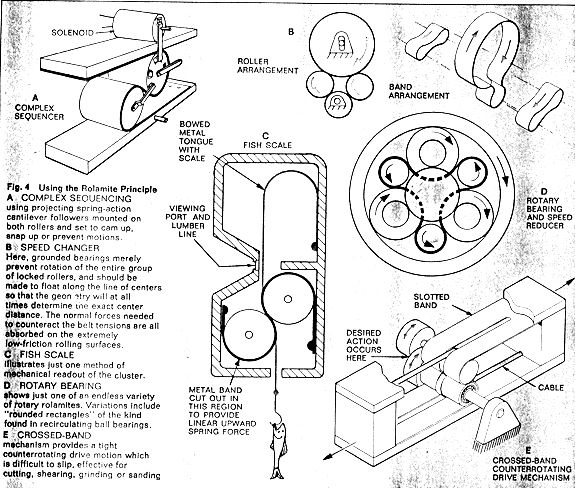
Rolamite devices can produce any type of force-deflection characteristic. Without adding more parts to a device, it is possible to obtain constant force levels, positive and negative spring constants, second order and higher force curves, detenting actions, etc., in any desired combination. These forces may be highly localized or distributed. Reasonably, sharp step functions and sinusoids are also obtainable.
The negative spring characteristics obtainable with the rolamite geometry are of particular interest. In the past the designer has been limited to the use of permanent magnets, buckling helical springs, and other rather indirect and imprecise methods, difficult to analyze and not accurately predictable, to achieve sharp breakaway or hair-trigger action. With rolamite, negative spring-constant or other negative force-deflection action can be achieved in exactly the right way with no additional parts. This opens up new fields for mechanical amplifiers, oscillators, and motion detectors, and may permit cheaper mechanical devices to replace magnets in many applications.
With rolamite the designer can incorporate the precise amount of viscoeleastic damping or coulomb friction desired, either continuously or as a function of displacement; he may directly clutch or brake a roller or both rollers, or provide overriding action or a local uncoupling; produce sequencing, extremely high direct speed or torque changes, maximum-minimum limit-stops, squeezing, latching, insertion, pullaway action, and recording.
The Beauty of the Band
It is indeed fortuitous that the key element in the rolamite geometry is the band, because, of all the engineering materials, thin metals are second only to tiny wires ad whiskers in excellence of mechanical properties, while concurrently they are optimal for one of the best manufacturing processes available --- chemical etching. This single element can provide forces, electrical circuitry, electrical contacting, programmed fluid resistance, sliding, latching, releasing, differential detenting, sequencing, maximum-minimum recording, differential action, sealing, metering, insulating, viscoelasticity, bimetallic behavior, etc. Although the band profile can be complex, the chemical-etching process requires only that a few master patterns be generated. Hence many of the aforesaid functions are obtainable at a low cost.
The suspension, bearing, and force features of rolamites are definite advantages. More important, however, is the versatile way the rolamite geometry can produce nearly all known mechanical and electromechanical functions in a wide variety of combinations using very few piece-parts (usually 4 to 10). This design versatility and economy stems from the many types of motion directly obtainable from the cluster, manufacturing tolerance and adjustability, and the simple, adaptable elements used. Although the rolamite geometry looks somewhat less promising for recirculating rotary speed changes and bearings, the lessons learned from the rolamite geometry relative to tip guidance, rolling separators, friction control through the angle of repose, and the value of compliant behavior could well point the way to greatly improved high speed rotary devices, ones which could operate without lubrication for long periods of time and which could be more economically manufactured than existing devices.
Part 2: Engineering
When the roller cluster is locked between the guide surfaces by sufficient band tension, and permitted to roll enough to relive forces induced by the tensioning process, the roller axes are perfectly parallel with each other and with the guide surfaces; therefore, the entire geometry is placed with its preferred minimum energy state (pure rolling state) because the tension in the band is at a minimum.
This rolling state is assured by the laws of flexure so that there need be no slippage between the band and rollers or between the band and guide surfaces as the locked geometry is rolled. Since the band tensions and the elastic strains induced in the band when it is bent around the rollers are equal and opposite, and because the rate at which strain energy is entering and leaving the band area adjacent to each of the rollers is constant, no net axial force is exhibited by the cluster --- that is, the cluster is essentially in neutral equilibrium at any position along the horizontal x-axis within the confines of the band and the guide surfaces. This balance is independent of the roller diameter.
Figure 5: Notation Used With basic Rolamite Geometry ~ The band tensions T acting through distance S set up a force couple which is balanced by the reaction force couple, N x A. the cluster is at equilibrium at any position, but free to move.

The parameters for defining the rolamite geometry are shown in Figure 5, where
T = band tension
N = normal
reaction force
S = spacing
between guide surfaces
A = axial
spacing (spacing between roller centerlines) measured parallel
to the guide surfaces
Alpha =
repose angle of the cluster
Gamma =
contact angle of the cluster
T = band
thickness (assumed constant)
The external normal reaction forces N appear on the cluster at points A and B to balance out the force couple introduced by the band tension.
Suspension Analysis
Constraints: Constraints are imposed on the geometry for several reasons: (a) Most commonly, the desire to insure fully elastic behavior in the band without any plastic deformation; (b) some minimum endurance limit on the number of cycles the geometry may undergo; or (c) the limitation of some feature in the locking cluster geometry. For simplicity, the following analysis is limited to cases where the band thickness t is constant throughout the working portion of the band.
In order to insure fully elastic behavior or some minimum endurance level for the band, the maximum strain induced by the combined effects of bending to conform with the roller diameter, and all other axial strains induced by initial tensioning, induced loadings, or through Poison's ratio effects due to normal loadings, must be kept below some maximum level.
(1) E* > Efmax + ET + EL + YEN
Where
E* (Epsilon*)
= design strain limit
Epsilon EFmax
= maximum tensile fiber stress induced by bending around
rollers
Epsilon ET
= strain induced by tension
Epsilon EL
= tensile strain induced by loading
Epsilon EN
= normal compressive strain
Y
(Gamma) = Poisson's ratio
In most situations, flexural strains are strongly dominant and if EFmax is set at about 70% of E*, a safe initial design estimate will emerge without a detailed consideration of the other terms until the design is approaching final form, at which time it will be easy to include approximations of these other terms.
To further simplify the following discussion, the assumption will be made that the band is perfectly flexible, that is, it has not flexural stiffness. The constraints imposed by the free-rolling locked cluster are: First, s - 3t (Figure 1) must be greater than the diameter of the largest roller, or interference will occur. Mathematically stated, this constraint is:
(2) (s - 3r) > d1
where
d1 > d2
Additionally, (s - 3t) must be smaller than the sum of the roller diameters, or the cluster will not lock. Thus,
(3) (s - 3t) < (d1 + d2).
Static Equilibrium: Cluster equilibrium requires that the moment induced by the nonaligned band tensions T must be counteracted by an equal and opposite moment induced by normal forces N, as shown in Figure 5. This requirement is expressed as
(4) TS = NA
and
(5) N/T = S/A
where
S = s - 2 (t / 2) = s - t
Tight Geometry: A real band has flexural stiffness, and a real rolamite arrangement need not be tight in order to present a true rolling geometry. An infinite tension would be required to pull a real band into true parallel tangency with a pulley, which is of course impossible because of the finite ultimate strength. The rolamite geometry is different because the moment introduced by band tension may be countered by the guide surface reactions to give an essentially tight geometry. An essentially tight geometry occurs when the tangent lines between the band and the guide surfaces and the band and rollers fall inside the contact interface area between the rollers, band and guide. This occurs when the tension is of the order of
(6) T ~> EI/tR'
where
E = tensile
modulus of elasticity
I =
cross-sectional area moment of inertia
T =
band thickness
R =
rolling radius
The exact tension for functionless tightness depends upon the elastic moduli of the materials involved. While it is usually possible to add sufficient band tension to produce an essentially tight geometry, the amount of tension required to do this is usually too high to allow really sensitive behavior; therefore most rolamites use geometries which exhibit some degree of looseness.
Figures 6 / 7: Loose Geometry Parameters ~ The arrangement is very tolerant of surface roughness, out-of-sound rollers, jamming caused by particles, and thus requires less manufactured precision.


Loose Geometry: Figures 6 and 7 show a typical loose geometry and define the parameters used to describe it.
The unsupported length of the band is inversely proportional to the applied tensile couple, whereas the normal reaction force is direcly proportional. A complete analysis exists which permits prediction of these parameters, given certain initial conditions, but is too detailed for inclusion in this article (see reference at beginning of paper).
For the loose geometry interaction, early all of the equations and analyses previously presented must be modified or qualified, or at least applied literally only when acting within certain limits. First, A* replaces A in these formulas and represents the axial distance between two outer contact lines between the guide surface and band.
The loose geometry also introduces it the cluster a degree of compliance which minimizes the effects of surface roughness, permits the cluster to accommodate minor variations in rollers (such as out-of-roundness) without balking, allows the cluster to ride up over particulate contamination without jamming, and in many ways reduces the criticality and degree of manufacturing required.
Rolling Friction: Friction coefficients for the rolamite geometry are designed as the ratio of the frictional force measured at one or the other roller centerline divided by the normal reaction force generated by the band tension.
The friction coefficients measured to date on various loose rolamite configurations using typical engineering materials without lubrication and with 0.205-inch to 0.500-inch roller diameters, have fallen in the range 0.0004 to 0.0016, with 0.0008 the expected value in...
[missing pages 18-19 --- under construction]
Part 3: Applications
Any desired proportion of the above seemingly paradoxical attributes may be achieved with a single device.
Rolamite devices can accommodate significant surface irregularities without jamming, roll over small foreign particles, and accept minor imperfections in their own geometry. Abnormally high forces and torques of unpredictable, infrequent, or sporadic nature such as may arise in accidents or rarely encountered environmental situations can be accommodated because of the band compliance; hence, the geometry is tolerant. However, after a perturbation has passed, the geometry will aggressively return to its lowest friction state. A rolamite suspension can be designed to be very tolerant (soft, flowing, almost fluid in action), moderately tolerant (but well controlled), or completely intolerant (uncompromising, invariable).
Force Amplification: There are many methods of rapidly extracting kinetic energy which have been imparted to the roller cluster by internal means such as springs, or by external means such as acceleration. Most of these methods permit the attainment of high force levels during the rapid deceleration of the roller cluster. Some of these methods make it possible to retain or entrap the high force levels. In addition, some of the methods tend to minimize, and some tend to maximize, frictional processes during the deceleration phase.
Figure 13: Offset Channel Force Amplification results from a change in geometry which in effect redcues distance A and thus increases the normal force N. Care must be taken not to make S too large or the rollers will unlock.

Typical methods of force amplification include the use of various types of wedging for the rollers and of offset channels. Figure 13 illustrates a configuration for obtaining normal force amplification caused by the sudden increase in guide surface spacing and by wedging under the high forces of deceleration. The moment equations for the initial and final states are
(8) TS1 = Ni Ai
and
TSf = NfAf
Here, if the geometry is made correctly, the initial band tension can equal the final band tension, or, from Equations (8) and (9),
(10) NiAi / Si = NfAf / Sf
from which the ratio of final to initial normal force can be found:
(11) Nf / Ni = AiSf / AfSi
Evaluating Ai and Af:
(12) A = {[ d1 + d2 / 2 + t ]} cos alpha
(13) Nf / Ni = Sf cos alphai / Si cos alphaf
As => Af , cos Af => 0 and Nf / Ni => infinity. Practically, Af cannot get too small or the rollers would be able to unlock because of the elastic deformation associated with Nf. This explains the force amplification resulting from sudden reductions in the axial roller spacing. The force attained through the rapid deceleration by wedging can best be estimated from the total energy supplied to the roller cluster by assuming a stopping distance delta. Here
(14) Fw ~ W / delta
where
Fw =
wedging force
W = input
energy to cluster
Delta =
deceleration distance
Slipping between the band guides and rollers would be precluded by the high contact angle. Friction locking, if desired, may also be obtained.
Figure 14: Detent Designs which hold or position the cluster until a breakaway force can suddenly release it. There are many methods of providing adjustment and just a few are shown. Rear roller detenting is preferred because the band provides a smooth radius to roll out of the groove and the tendency to jam is less. Conversely, front roller detenting is better when very high breakaway levels are needed.

Detenting Mechanisms: There are many methods of detenting, that is, holding or positioning the roller cluster until some desired breakaway force or energy level is experienced, and then suddenly releasing the cluster. A few types of detents are shown in Figure 14.
A guide surface slot is one of the simplest types of detents and its breakaway level may be adjusted by varying the distance the roller is permitted to drop into the detent or by adjusting the band tension.
Figure 15: Roller-Flat Detenting utilizes the normal force for breakaway. It is a function of tan 0 (providing 0 is small). Adjustable stop can also be applied to this type to partially rock the roller forward (i.e., reducing 0 ).

Figure 16: Negative Spring Detent force opposes weight. The screw is turned until the desired breakaway level is reached. Thereafter the energy surplus causes a fast breakaway.

Another method of detenting shown in Figure 15 is to flatten an area on the surface of one roller so that the normal force induced by the band tension at the point of tangency of the roller and guide surface can be used to provide a breakaway force level. The rear roller is the preferred location for frictional locking to occur during breakaway. If desired, an adjustable stop can be used to rock the roller forward and partly out f the detent notch to diminish the breakaway level for calibration purposes. One such arrangement is shown in Figure 16.
Accurate and repeatable breakaway level detent action is obtained by using detents which are provided by a negative spring-constant region containing the desired force level. Negative spring constants may be achieved by such means as cutouts in the band or preformed curves. Of course, the steeper the negative slope region, the sharper the breakaway action. Once the set force level is exceeded, there is clearly an excess of force.
Figure 17: Disc Braking wedges a bar against the wall (or the other roller in the inter-roller version). The forces involved in the sudden deceleration are at a minimum. If braking were to occur on the lower wall (cluster moves to left), the roller would attempt to roll up on the bar and severe damage could result.

Braking & Clutching: Stopping the roller cluster directly by over-roller or inter-roller braking (Figure 17) is primarily useful I a high-shock situation in which the cluster must not impact against the end of the device. For example, in over-roller braking, the bar wedges between the upper side of the roller and the wall, providing quick friction braking. Gradual friction braking would be useful in extremely high axial shock or acceleration situations. Gradual braking can minimize the loading on the side walls, rollers, and end caps after an extremely high kinetic energy level has been attained by the cluster (See Figure 18).
Figure 18: Gradual Braking is similar but uses a compressible pad instead of a rigid bar. It minimizes the loading on the walls and rollers when extreme speeds are reached by the cluster.

Figure 19: Band Tension Clutch is the simplest form. When the pin is removed, the tension is released and the rollers are free to rotate in place.

Figure 20: End-of-Stroke Decoupling is shown here with one roller part of a flywheel. The shaft socket is not a necessity but it does reduce friction. A positive stop is provided for the upper roller to prevent wedging.

The simplest form of friction clutch is one based on controllable release and reapplication of band tension, as shown in Figure 19. Another version of this clutch can be used to decouple the rollers at the end of a stroke. This is also depicted in Figure 20 in a situation where one of the rollers functions as a flywheel. Decoupling at the end of a stroke may be necessary so that the rotary kinetic energy will not have to be rapidly absorbed, or it may be desirable to use this rotary kinetic energy to accomplish some other task.
Figure 21: Dual-Action Overriding Clutch ~ Forcing the top roller to the left, or lower to the right, causes jamming and the cluster becomes friction-locked, but in a rollable attitude. The asterisked forces are used for release.

The use of a high contact angle (gamma) for the cluster and a relatively stiff band only lightly tensioned permits attainment of overriding clutching action for the cluster. This capability is depicted in Figure 21. Driving or forcing the top roller to the left or the bottom roller to the right causes the rollers to jam with a tendency to further increase gamma. Jamming causes the normal force N to increase, as predicted by Equation (15), and the geometry becomes friction-locked in a rollable attitude (FT or B is the driving force applied to the top or bottom roller).
(15) N = TT or B tan gamma
and, since tan gamma, for gamma's very close to 90 degrees, is very large, N will be large; consequently, the frictional forces will be large even if FT or B is relatively small.
On the other hand, driving or forcing the top roller to the right or the bottom roller to the left by the forces designated by an asterisk in the figure causes the rollers to tend to decouple and decrease gamma. The only torque required to turn the rollers is that required to overcome the frictional torque between the loose band and rollers. The coupling or decoupling forces can be applied in any way to the rollers, not necessarily by means of drums or tongues as shown. The coupling forces must at least permit rotation, but the decoupling forces can be applied so as to preclude gross rotation. However, considerable force would have to be provided initially to break the friction coupling to achieve decoupling if at least a small amount of rotation were not permitted.
Sequencing, Recording & Limiting: The rolamite geometry can be used to insure that a certain combination of input function types, signatures, directions, or amplitudes be experienced by the device in the proper sequential order for output to be permitted at some later time.
Figure 22 / 23: Sequencing by means of a short tongue feed through, in (1) the tongue is on the rear roller; (2) passing through; (3) the tongue has popped up; (4) end of the stroke. Reversing the cluster can go back to (3) but no farther since the erect tongue will not pass between rollers. The photo shows several short tongues and also a long tongue used to move the cluster.


There are some distinct ways in which the geometry can provide the sequencing behavior. One method utilizes the short-tongue feed-through arrangement shown in Figure 22. In the initial position, position 1, the short tongue is on the left or rear roller; in position 2, the tongue is just passing through between the roller; in position 3, the tongue has popped up again; in position 4, the end of the cluster stroke, the tongue can be used for contacting or some other function.
Upon reversal, the cluster may return to position 3, but is not permitted to go any farther because the erect tongue will not pass through the rollers. Combination of this action with a specially shaped force-deflection bias provided by the band, and possibly additional detenting action, could provide a very sophisticated sequencing routine, like that of Figure 23.
Figures 24 / 25: Simple Speed Changers ~ The photo demonstrates how the speed ratio can be changed using the same guideways. Sketch (b) shows an inertially restrained speed changer.

Figure 26 / 27: The photo is a model of a variable surface velocity selector in which there are seven linear speeds available in addition to cluster speed. The drawing shows an inertially driven oscillator with variable surface speed and amplitudes.
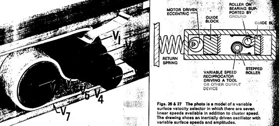
Figure 28: Multiple Roller Cluster arrangement which provides many different relative rotational velocities all moving at the same linear speed. Multiple clusters also can serve to increase the total wetted perimeter of the band so that more travel with a force bias can be achieved, or to increase the number of sequencing functions one short tongue can perform.

Speed Changing: Figures 24-28 show a few of the speed-change possibilities. Single-stage speed changes have been successfully demonstrated in which step-up and step-down rations as high as 300 to 1 were used.
Both linear speed ratios and angular velocity ratios are available according to rolamite arrangement or usage.
Types of Motion: Cycloidal types of motion which are available provide excellent sources of contacting, cutting, counterbalancing, and instrument indicator actions and can approximate almost every type of planar curve. Certain portions of the trajectories exhibit extremely high mechanical advantages as well. The roller counter-rotation can provide ideal action for fusing, aligning, valving, etc., or can be employed to permit either response to or rejection of angular acceleration inputs (See Figure 29).
Figure 29: Types of Motion such as cycloidal and trochoidal are available by attaching parts to the rollers. Path 1 is on the surface of the roller. Paths 2, 3, and 4 show the effect of an increasing radius and illustrate the motions of points on a flywheel, for instance.

Counter-rotation can also be used to provide counter-balancing with respect to all inertial inputs. Because cluster motion in either direction provides both clockwise and counterclockwise motions, the designer has additional flexibility in solving his problems. The inertia-to-mass ratio can be regulated by roller design to produce cluster behavior approaching that of a point-mass on the one extreme, or can be maximized by employing rollers with flywheel proportions to provide long-range inertial odometer behavior.
Pumping Fluids: The conventional cluster becomes a very effective frictionless piston if a rectangular tube with a small side clearance is used to house and provide guidance surfaces for the cluster. The band tension provides normal forces which neatly seal the rollers at the three contact zones of Figure 10, A, B, and C. Side-guidance surfaces in the channel prevent tip leakage in two of the three short leakage path areas and permit the device to work in any orientation without appreciable wear or friction.
By using a collapsible tube in conjunction with the band, as shown in Figure 30, a much smaller displacement of fluid per inch of cluster stroke may be obtained.
Figure 30: Pumping Arrangement using a collapsible tube squeezed between the rollers. Note that in the photo the band is not continuous as though it were with respect to the tube. The pumping stroke is applied to the loose end moving it to the right. The spring provides the return force. In an actual pump, of course, check valves would be needed. Any desired fluid displacement per inch of stroke is easily obtained by roller sizes and tube diameters.

Sensing Temperature Change: If the band is suitably made of bimetallic materials, the cluster can be made to respond sensitively to temperature changes induced environmentally, internally by dissipation of electrical energy, etc. The low rolling friction of the cluster permits high band tensions to be used without introducing appreciable friction, so that the output force or energy from a bimetalically driven device can be sizable. Tow useful methods of accomplishing thermally induced bimetallic driving of clusters are shown in Figures 31-33
Figure 31: Single-Band Thermostat employs a bimetallic portion of the band to counteract the triangular cutout.

Figure 32: Two-Banded Thermostat uses a bimetallic strip fastened to one roller opposing a spring-loaded band.

Figure 33: Snap-Action Thermostat has a full band, but this cut-out yields a negative spring constant. The bimetallic element looks like Figure 32 but actually is preformed and thus tends to move the cluster to the left. At a high enough temperature this tendency is insufficient and the cluster snaps to the right.

Electrical Contacts: Many of the means for locally amplifying forces while also permitting some relative sliding are suitable for electrical contacts. The combination of high force and sliding action insures that the contact surfaces penetrate through and scrub off oxide films, contaminants, and particles which would prevent clean repeatable contacting: Figure 34.
Figure 34: Cross-Curved Band ~ In going from A-A to B-B the tape flattens out, undergoing a sliding action with high unit forces at the edges. Since the curvature with respect to the guide surface at E-E is in the opposite direction, the same action does not take place.

Figure 35 / 36: Side-Buckling Contact Electrical Switch utilizes the action described in Figure 34. This continuous wiping motion cleans oxides and contaminants, thereby providing dependable electrical contact. Figure 36: Cut-Out Roller Contact (right) ~ During the scrubbing phase, differential sliding occurs because the point of contact is no longer the rolling radius of the roller.


Figure 37: Contact Orientations ~ Repulsive opens by itself if the driving force is removed. Neutral stays closed but opens easily. Locking requires considerable force to open.

In addition, the high-contact pressures help insure low ohmic contacting. Figure 35 shows one arrangement for achieving this action. With the cutout roller contact of Figure 36, the roller centerline need not lift up to achieve contact engagement. Once the unbacked portion of the band begins to touch the contact block and is deflected inward, differential sliding occurs since the contact point is no longer at the rolling radius of the roller. This insures that contact scrubbing action will take place.
Three orientations of the contact block relative to the final rest position are of interest. One gives a repulsive contact (one which tries to open itself if the driving force is removed), one gives a neutral contact (one which will stay closed but which will open very easily), and one give a latching contact (one which requires considerable force to open): Figure 37.
Part 4: Hardware
Bands: Bands for use in rolamite geometries may be made of any material which is strong under tensile loading and flexible enough to undergo the required number of cluster movement cycles (Figure 38). Usually this also means that the flexing cycle should not permit plastic behavior unless such behavior is to damp out oscillations. In any situation, however, the active regions of the bands will necessarily be thin relative to the roller diameters with the ratio of t/d < 0.020 in most cases.
If the flexural and tensile properties only are important, the best performance will be given by band materials which yield the highest ratios of yield stress divided by the tensile modulus of elasticity. For a given thickness of band, such materials would insure the lowest maximum stress; or if maximum tensile strength is needed, they would permit using the strongest band without obtaining plastic behavior.
Maximizing this ratio does not necessarily minimize the frictional losses displayed by the rolamite cluster. Flexural hysteresis losses can be minimized by using a material which exhibits minimal internal damping while displaying a high ratio of yield stress divided by the tensile modulus of elasticity. And then selecting roller diameters, shapes, widths, etc., which permit minimizing the ratio of t/w where w is the band width.
Rolling friction losses can be minimized by employing high modulus materials for the rollers, guides and bands, by using the best available surface finishes, by reducing the coefficient of sliding friction between the rollers and guide surfaces and the band, by using dry lubricants, surface coatings, oxides, etc., and by using the lowest band tension consistent with performance requirements. To date, all of Sandia's rolamite devices use metal bands or plastic-metal composite bands where insulated electrical conductors must be provided within the active portion of the band but several devices with plastic bands of Mylar, Kapton, and Teflon-impregnated woven fiberglass have operated satisfactorily.
Not only must the band material be carefully selected but also the exact condition of the material must be controlled if a consistent repetition of behavior of subsequent units is to be achieved. Sandia has found that several of the age-hardening spring metals in their fully cold-worked and age-hardened state best fill the present rolamite component needs by offering high yield strengths while retaining enough elongation to eliminate a critical crack propagation situation. Spring metals used include such alloys as beryllium copper 25 and 17-7 PH stainless steel.
The bands may be shaped by standard processes such as machining or chemical etching, or controlled electroforming.
In general, those methods which do not raise burrs or cause thickness variations are preferable even if the width definition is not highly refined. In the axial force equation the thickness terms appears raised to the third power while only the first power of width applies. Therefore, whether axial forces are to be generated intentionally or not, variation in the band EI (where I is the cross-section area moment of inertia for the band) introduced by the band material fabrication process will result in axial force variations.
In addition to the variations which are useful in or near the working portion (that portion which is actually permitted to flex as the cluster moves between its two limiting positions), several other types of features become useful only in regions of the band well removed from the working portion. These features may provide structural attachment, positioning, electrical circuitry, electrical circuit termination, electrical contacts, electrical connector pins or sockets, electrical cabling, electrical connectors, mechanical fastening, auxiliary side bands, commutating contacts, potentiometer resistive elements, and lateral compliance. Having these features provided by the band can insure fabrication and assembly advantages over separate piece-parts.
The structural portion of the band can be made of material of any required thickness and joined to the thin active layer or layers by means such as spot welding or silver soldering, which would leave metal interfaces conductive, or through use of insulating adhesives and additional plastic films if desired. By having these additional layers provided only where they are needed, many additional processing steps are eliminated and a minimum amount of material wastage occurs.
By adding these layers as continuous strips to a full-width backing layer, special flexible strip laminates are obtained, permitting the band patterns to be arrayed transversely very closely spaced. Thus, a very efficient manufacturing process becomes possible for the automated production of highly sophisticated rolamite bands which are capable of replacing a great umber of individual parts.
Rollers: Although not quite as subject to variations as the bands, the rolamite rollers may have several different configurations other than the simple straight right circular cylinders shown thus far. Such changes would allow the ratio of inertia to linear inertia to be varied, for example.
Figure 38:

Figure 39:

Multiple threads could be used to provide two regions of clearance between rollers and guide surfaces. Circumferentially grooved rollers could be used for attaching, adjusting, stopping, or coupling adjacent clusters. Single and double hubs could be used for weight and inertia control. Single and double cups could also be used for weight control and to provide room inside rollers for some useful purpose. Flanged rollers could provide guidance and permit sustained operation in the presence of side loads.
Parallel Support Geometry: Parallel plates and channel forms allow access to the rollers, rectangular tubes provide good strength-to-weight ratios and band attachment and alignment characteristics. Cutaway tubes combine several of the foregoing attributes. Compliant guide surfaces allow automatic tightening of the band and provide cluster compliance (Figure 40).
Figure 40:

Several useful features may be incorporated in the support geometry. Notches may be used for detenting, decoupling, clutching, etc. barriers or bumps are useful for stops or energy level detents. Changes in level are used in detenting and in changing the cluster repose angle. Divergence in the support can provide gradual changes in cluster tension, axial force, etc. Undulations allow soft detenting and slow decoupling. Wedges provide braking actions and force amplification or attenuation.
Summation
The rolamite geometry is adaptable to modularity, microminiaturization, and a very broad calibration of forces. Additionally, it can utilize the highly desirable advantages of multiple-use laminates, which may be the first step toward the ultimate in manufacturing efficiency --- one-piece mechanisms for continuous-strip processing techniques.
Good performance has been attained in the many devices and prototype mechanisms assembled to date. Yet the rolamite technology is in its infancy and much remains to be learned if the full potential of rolamite is to be exploited. Most of the instrumentation and testing methods required to record completely and accurately rolamite behavior, particularly in microminiature sizes, are either nonexistent or in the early stages of development. It is clear, however, that the use of the rolamite geometry is an effective way to design electromechanical weapon components and that the rolamite geometry can be used to advantage in many applications, including electromechanical weapons components, biomedical components, household devices, toys, and so on.
US3452175
Roller-Band Devices
Donald
F. Wilkes
[ PDF
]
Abstract -- A roller-band device which substantially eliminates or minimizes sliding friction; the device having a plurality of rotatable members in a guideway with generally equidistantly spaced walls, with each wall supporting and restraining one of the rotatable members and separated from each other less than the summation of the diameters of the rotatable members, and a flexible band between the guideway walls having a portion disposed between the rotatable members at leas partially encompassing at least one member, the band holding the members with generally parallel axes and providing rolling motion between each element of the device.
Background of the Invention
In prior electro-mechanical and mechanical devices which transferred one form of motion or energy into another such as bearings, gear systems, condition sensitive switches, etc., the accuracy, efficiency, and sensitivity as well as the life of the devices have been limited by the degree or amount of sliding friction inherent in the device or sliding friction resulting from structural inaccuracies in the elements used in the device. In attempting to compensate or minimize sliding friction losses, compromises in construction are sometimes made which contribute further limiting factors in efficiency and sensitivity of the device under some operating conditions.
Attempts to minimize friction often resort to lubrication of the moving parts with various liquid, gaseous or solid lubricants. These lubricants may create forces which are detrimental to the operation of certain devices under highly sensitive operating conditions. The lubricant may contaminate critical areas within the housing or a portion thereof and require packing or sealing materials to prevent contamination and thus create other friction losses. Further, under extreme operating conditions such as high and low temperatures and prolonged storage, lubricants may not perform in the desired manner and may effect either partial or complete device failure.
The efficiency of land bearing surfaces has always been limited by the ability to fabricate precision surfaces or dimensions. For instance, in bearings such as roller-bearings, misalignment of rollers results in end frictional losses and attempts to provide closer alignment with caging frequently results in additional frictional loses therebetween. If the losses in adjacent roller ends can be minimized, surface roughness on the rollers may cause additional losses which may substantially exceed any attainable rolling coefficient of friction, thus placing a lower limit on overall efficiency.
In devices such as accelerometers or G-switches, attempts to increase the accelerometer's sensitivity by decreasing sliding friction between the various elements of the device may also decrease the force applied between the electrical contacts closed by the devices reactions an acceleration force since this force is generally dependent upon opposing sliding members. Further, such devices generally may not be adjusted to respond accurately to a relatively wide range of acceleration force due to unpredictable and variable frictional losses between the device's members.
Prior electrical potentiometers are also dependent and limited y sliding frictional forces between the contacts or contacts and resistance material. Any attempt to decrease the sliding frictional force to increase component life or sensitivity may result in a decrease in resistance linearity.
The problem became particularly acute in modern microminiaturized technology since the adverse effects of any friction may be greatly amplified relative to the size and forces available to activate the device. It has been shown that the friction force approaches a constant level for normal loading under about 10 grams, which makes it hard to achieve a reasonable driving force to friction ratios in microminiature devices. Further, it is difficult to fabricate these devices so that they can perform multiple functions or provide a complex response to a predetermined or desired situation, environment or event. For instance, it may be desirable that a G-switch have one or more open or closed electrical contacts in its quiescent state, be accurately adjustable over a given range of acceleration force, be capable of sensing whether the acceleration force continued for at least a given period (and if not have automatic reset capabilities), be stable over long periods of time and over wide ranges of operating conditions, have one or ore open or closed electrical contacts in its activated state, provide latching in its activated state, and be relatively sensitive to load components not on the sensitive axis.
It is desirable in this area of technology that a mechanism or apparatus be capable of modular construction, e.g., that the mechanism be constructed of standardized parts that can be assembled to perform a wide range of functions depending of the particular parts used and the environment in which the device is used. Using a given module, a wide range of devices can be fabricated using mass production techniques to perform a wide range of functions without providing separate tooling and production facilities for each device. Such modular construction can provide commensurate per unit tie and cost savings while permitting the facility to be converted in a minimum of time to the production of another modular device performing an entirely different function.
Sliding friction may be decreased by further precision fabrication, closer tolerances and the use of such sophisticated techniques such as air bearings. However, there is generally both a financial and a technology limit to these approaches and the devices become increasingly sensitive to environmental conditions such as temperature, moisture and surface contaminations such as with dirt or dust.
Since rolling coefficients of friction are considerably lower than sliding coefficients of friction, it is desirable to provide electro-mechanical or mechanical devices having only rolling friction losses. Rolling coefficients of friction have been measured as low as about 0.00001 to 0.00002 for right circular cylinders whereas roller bearings and ball bearings have attained coefficients of friction of only about 0.001 to 0.005 due to the loss mechanism noted above and several others which have not been mentioned.
Summary of Invention
In view of the limitations of the prior art such as noted above, it is an object of this invention to provide mechanisms having substantially only pure rolling friction losses.
It is a further object of this invention to provide mechanisms exhibiting low coefficients of friction without use of lubricants.
It is a further object of this invention to provide mechanisms having substantially no adverse effects from surface deformities on load bearing surfaces.
It is a further object of this invention to provide electrical switch mechanisms having only rolling friction losses while having high contact pressures.
It is a further object of this invention to provide mechanisms which may have force biases applied thereto.
It is a further object of this invention to provide mechanisms having adjustable negative force bias with only pure rolling friction losses.
It is a further object of this invention to provide a substantially frictionless piston mechanism which may be displaced by or may displace fluids.
It is a further object of this invention to provide mechanical bearings having only rolling friction losses.
It is a further object of this invention to provide mechanisms having only rolling friction losses which are capable of modular construction.
The invention comprises a roller-band device having a guideway with oppositely spaced walls, at least a pair of rollers intermediate the guideway walls with combined cross-sectional dimension greater than the spacing between the walls, and a flexible band supported within the guideway and reversibly looped about the rollers so as to effect rolling movement of the rollers and band longitudinally along the guideway.
Description of Drawings
Embodiments of the present invention are shown in the accompanying drawings wherein:
Figure 1 is a side elevation view, partially in cross-section, of a roller-band device with generally parallel guideway walls and right circular cylinder rotatable members;

Figure 2 is a side elevational view, partially in cross-section, of a roller-band device of the type shown in Figure 1 but with uninterrupted guideway walls;

Figure 3a through 3l are diagrammatic views of tension band configurations and the resulting force biases;

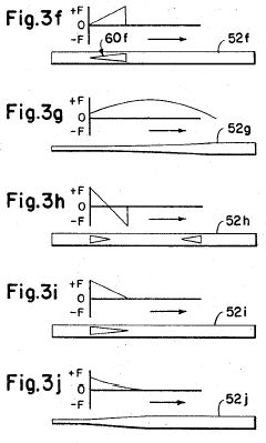

Figure 4a is a view of a tension band having electrical conductors embedded therein;

Figure 4b is a cross-sectional view taken along line B-B of Figure 4a;
Figure 5a through 5c is a side elevation view, partially in cross-section, of a portion of a roller-band device showing various rotatable member geometries;
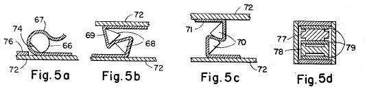
Figure 5d is across-sectional end view of a roller-band device having spool-shaped rotatable members;
Figure 6 is a cross-sectional side view of a roller-band G-switch;

Figure 7 is across-sectional view taken along line 7-7 of Figure 6;

Figure 8 is a view of the tension band shown I Figure 6 and the force diagram of the tension band;

Figure 9 is a cross-sectional side view of a roller-band device which may be used to sense or measure acceleration or velocity;

Figure 10 is a side-view, partially in cross-section, of a 2-level accelerometer G-switch;

Figure 11 is a cross-sectional side view of the present device as it may be used to pump fluids;

Figure 12 is a cross-sectional view of the device utilized as a speed converter;

Figure 13 is a cross-sectional side view of a roller-band electrical potentiometer embodying the present device;

Figure 14 is a cross--sectional side view of the roller-band device utilized as a force amplifier;

Figure 15 is a cross-sectional side view of a heavy load-bearing roller-band device; and

Figure 16 is a side elevation view, partially in cross-section, of a roller-band device having a curved or arcuate guideway and right circular cylinder rotatable members.

Detailed Description
By way of introduction, the mechanism shown in Figure 1, which may be referred to as a "roller-band" device, illustrates various features and principles of this invention. As shown, roller-band device 10 includes a group or pair of adjacent rotatable members or rollers 12 and 14 supported between equidistantly spaced restraining surfaces or walls 16 and 18 of a guideway by a flexible, tensioned band or ribbon 20. Band 20 extends in generally S-shaped configuration partially around members 12 and 14 and may be held under tension by suitable fasteners 22 and 24, such as screws or bolts, which attaché band ends at opposite extremities of the guideway on opposing walls. The guideway walls 16 and 18 are supported at either end by end blocks or walls 26 and 28. The summation of the diameters of the rotatable members is at least slightly greater than the distance between walls 16 and 18 of the guideway.
In the embodiment illustrated in Figure 1, rotatable members 12 and 14 may be right circular cylinders of any convenient length. Tension band 20 in this embodiment may be a flat elongated band of any convenient constant width and any convenient thickness. For purposes of illustration, tension band 20 is shown with exaggerated thickness since generally it may be from about 0.0002 to 0.004 inch thick for instrumentation usage. The guideway, which includes walls 16 and 18, may also include side walls (not shown) depending on the application of the invention.
As shown rotatable members 12 and 14 are in an initial position with member 14 and the corresponding contiguous portion of tension band 20 in latch or detent 30 in wall 18. If a predetermined force function is applied in the direction of the arrow (for example by acceleration of the device toward the left) which is sufficient to overcome the forces of tension band 20, inertia of members 12 and 14 and band 20, the coefficient of friction (e.g., rolling friction), and the band tension holding roller 14 in detent 30, member 14 may be released from the detent. If this force function or some lesser force (now only dependent on the band tension friction and inertial forces) continues, members 12 and 14 may continue to roll along the guideway until the force function is discontinued or members 12 and 14 may continue to roll along the guideway until the force function is discontinued or member 14 reaches energy barrier 32. If sufficient force is applied over the travel of the rollers to raise the kinetic energy above some threshold provided by the combination of height and width of the barrier and the increased tension placed n tension band 20, the members may roll over barrier 32 and drop into latch or detent 34 as shown by the dashed representation of the rotatable members and tension band. In order to unlock the roller-band device in a reverse direction, a force would have to be applied in the opposite direction to overcome both detent 34 and barrier 32.
Roller-band device 10 may operate a switch contact or microswitch 35 or be provided with electrical contacts on the ends of either member 12 or 14 and on the appropriate wall of the guideway, or tension band 20 can be used as an electrical contact and another contact provided within detent 34 in wall 18 so that an electrical circuit is completed when member 14 reaches detent 34. thus, the roller-band device shown in Figure 1 may be used to measure or sense a force or combination of forces and the integration of the forces over a given time determined by the length of the guideway. Such devices can be released from detent 30 and rolled over barrier 32 with an accuracy of plus or minus a fraction of a percent of predetermined force levels.
With the general construction and operation of the Figure 1 type of device in mind, reference will now be made to the simplified roller-band device of Figure 2 in order to explain more of the principles of the device. As in Figure 1, roller-band device 42 includes a group or pair of adjacent rotatable members 44 and 46 supported between equidistantly spaced walls 48 and 50 of a guideway by a flexible tension band 52. Rotatable members 44 and 46 are shown in an initial position adjacent end wall 47, with the band 52 shown departing from contact with walls 48 and 50 at contact "lines" or lines of tangency 54 and 56.
As the band 52 is looped or threaded around members 44 and 46 and fastened under tension by suitable means to diagonally opposite ends of walls 48 and 50 of the guideway, the band tension produces a torque which urges the rotatable members firmly toward their respective restraining walls 48 and 50 and holds their axes parallel to each other, the combined effect of band tension and restraining walls being to urge the rollers firmly toward each other. With the rollers in the noted initial relationship, the position of the contact lines or zones may be varied to an extent by changing the tension of the band.
By way of explanation, it appears that the force (F) to effect movement of the rotatable members contributed by any one of the three rolling contact zones (at contact lines 54 and 56 and between rollers 44 and 46) is equal to the coefficient of rolling friction (mu, u) times the applied normal force (N) at that zone induced by the tension band and inertial forces. At any one zone:
(1) F = uN
so for the entire geometry, the total frictional force (Ft):
Ft = u1N1 + u2N2 + u3N3
The normal force (N) results from the tension applied to the band and the inertial forces of the system. Since the inertial forces of the rotatable members and band and the coefficient of friction are relatively small, the tension applied to the band may be the primary variable used to control or predict (F).
Since the tension band 52 is shown bent around a portion of each member 44 and 46 in opposite directions, energy stored elastically in the S-shaped part of the band applies opposite resultant forces which emanate from the axes of each rotatable member, likewise the axial components of these forces Fb in opposition in the direction of each band parallel to the guideway walls at each contact line or zone is defined by the following formula where force is measured at the center of one or the other where:
(3) Fb = WEh3 / 12R2
where
W = width of band at
line contact,
E = modulus
of elasticity of band at line contact,
R = radius
of rotatable member, and
h =
thickness of band at line contact.
If the band parameters W, E and h are equal at both zone or lie contacts 54 and 56 and the radius of the members are equal, the opposing forces (Fb) will be equal and the roller-band device will be in a state of equilibrium or rest in the absence of any external forces. The direction and magnitude of these forces are essentially independent of the band tension. Because one or more of the parameters of the band may be different at line contacts 54 and 56 (defined as positions 1 and 2 respectively):
(4) Fb1 /
Fb2
resulting in an unbalanced force (Fr) being applied to the rotatable members. If for instance force Fb2 is larger than the force Fb1, the force bias (Fr) will be applied to the rotatable members in the direction of the arrow. If the width (W) of the band is varied, the formula for the unbalanced forces becomes:
(5) F1 = (W1 - W2) Eh3 / 12R2
The other variables, E, h and R, may be varied to apply a force bias to the rotatable members.
Axial forces may be introduced by employing a band with preset loops or curves. These loops or curves may be formed by conventional tempering or cold forming processes. Forces may also be introduced by varying the material longitudinally in the band by laminating or connecting together various materials along the band by conventional processes.
Figures 3a to 3l illustrate various tension band configurations which provide various band width combinations at the line contacts with the guideway walls showing the resulting force bias (Fr) applied to the tension band and consequently the rotatable members. The tension band configurations in Figures 3a to 3l will be applied to the roller-band device 42 shown in Figure 2. IT will be assumed, for purposes of illustration, that the vertical axis of the force diagram in each of the drawings crosses tension band 52 at contact line 56 adjacent member 46 and that a portion of band 52 which partially encompasses member 44 is contiguous with the end wall of roller-band device 42.
In Figure 3a, tension band 52a has a uniform width throughout this length. Since the width of the band at line contacts 54 and 56 are equal, the resulting force (Fr) is zero as shown in the force diagram. This is the same configuration described with reference to Figure 1.
In Figure 3b, tension band 52b has a rectangular cutout 60b which begins to the left of line contact 56 in Figure 2 and continues around rotatable members 46 and 44, stopping just short of line contact 54. The distance of contact this represents is also the maximum travel the geometry can undergo without passing out of the force zone. Using Equation 5 above, cutout 60b generates a constant resulting force (Fr) in the opposite direction of the arrow in Figure 2 (a positive force) for the time in which the cutout 60b is adjacent the line contact 56. Using tension band 52b with the roller-band device 42 of Figure 2, the roller-band device may be used to measure forces, such as acceleration forces, in the direction of the arrow and the period of the force. If a negative force which is greater than the force of the band cutout is applied to the roller band device, the members and band may rotate may rotate along the guideway for the duration of the force. If the force continues for a time sufficient to allow the members to move to a second position having line contacts 62 and 64 as shown by the dashed lines in Figure 2 which are beyond the cutout, the resulting force bias on the tension band will be zero and the tension band will be in a state of equilibrium. If the force does not continue for a sufficient time to allow the members and tension band to reach line contacts 62 and 64, the force bias will cause the members and tension band to return to its initial position against the end wall.
Roller-band device 42 with tension band 52b may also be used as a condition sensing switch by positioning the rotatable members and band to the right of line contact 56 with cutout 60b still adjacent to the line cutout and physically holding the member in that position by a condition sensing means such as a fusible material or a releasable magnetic latch (not shown). Should the desired condition occur, the conditioning means may release the members and allow them to return under the tension band force bias to the end wall of the device and thus energize a switch (not shown). Such a device may be used, for example, as a circuit breaker or a circuit fault sensor.
In Figure 3c, tension band 52c is tapered at a uniform rate throughout the entire length of the tension band. Since the difference in width of the tension band at the line contacts for each rotatable member will be the same along the entire length of the guideway, the resulting force (Fr) is constant. The tapered band force is not limited by the length of the contact of the band with the rollers as in cutout 60b in Figure 3b. Using mechanical latching such as that shown in Figure 1 and the concepts described with reference to Figure 3b roller-band device 42, having tension band 52c, may perform the same functions as band 52b.
It will be apparent that tension band 52c may have a uniform width and a uniformly tapered cutout throughout its length to provide the same force bias.
In Figure 3d, tension band 52d includes a complex cutout 60d, a portion of which may be adjacent line contact 56 in configuration shown in Figure 2, and a second cutout 58d, which may be adjacent line contact 62 and member 44 as shown by the dashed lines in Figure 2. Cutout 60d provides a similar positive force bias as cutout 60b in Figure 3b except that the force bias has three force levels with step changes between each level. Cutout 58d provides a negative force bias which may function as a latch similar to mechanical detents or latches 30 and 34 in Figure 1. The step function force bias generated by cutout 60d may perform the same function as mechanical detent 30 in Figure 1.
In Figure 3e, tension band 52e includes a pair of triangular cutouts 58e and 60e. The base of triangular cutout 58e may be adjacent line contact 54 at one end of the force bias while the base of triangular cutout 60e may be adjacent line contact 64. the combined force bias generates a curve similar to a positive spring constant having a stable position where the force bias crosses the force diagram axis, e.g., where the apexes of the triangular cutouts are both simultaneously adjacent to a line contact about midway between line contacts 54 and 62 and 56 and 64 respectively. A roller-band device using tension band 52e may be used, for example, as a shock absorber or vibration damper.
In Figure 3f, tension band 52f includes a triangular cutout 60f having its apex adjacent to line contact 56. The resulting force bias, like Figure 3e s similar to a positive spring constant exhibited by a helical spring.
In Figure 3g, the generally concave tapered band width configuration shown produces a parabolic shaped force bias, thus providing both a positive and negative spring constant type force curve.
In Figures 3h, 3i and 3j, various cutouts and band width changes in tension bands 52h, 52i and 52j generate force biases which are similar to a negative spring constant force pattern. These cutouts and width changes operate on roller-band device 42 in the same manner as shown in Figures 3e, 3f and 3g and described above. By positioning the line contact of either tension band 52h, 52i or 52j adjacent rotatable member 46 along the force bias curve, a wide range of forces can be measured by roller-band device 42 using a single tension band geometry.
Figure 3k illustrates an arbitrary force bias which may be generated by a tension band such as band 52k merely by selecting the force bias desired and then design an appropriate cutout or cutouts.
In Figure 3l, the two series of circular cutouts in tension band 52l generate a generally sinusoidal force bias. Such a force bias may be used to provide multiple stable or detent positions for rotatable members 44 and 46.
By choosing one or more of the cutout or band width configurations illustrated in Figures 3a to 3l or variations and combinations thereof, any desired force bias may be generated with roller-band device 42. There are some applications where it may be desirable to use a primary force biased or non-biased tension band and rotatable member pair in conjunction with one or more secondary tension bands with or without their own rotatable members having separate force biasing to obtain a desired composite force biasing. The additional secondary tension bands may act as a pusher or damping on the primary tension band. Another typical force bias will be illustrated in Figure 8 which may be used in particular applications of the principles of this invention. For most applications it is preferable to provide the desired force biasing with cutouts rather than vary the outside dimension of the tension band since the cutouts can be formed more precisely with conventional techniques such as photographic etching processes.
The tension band may be of a wide range of flexible materials or combination thereof depending on the particular application of the roller-band device such as plastics, metals, alloys, laminates, insulators, viscoelastic materials, etc. Typical materials include aluminum, stainless steel, beryllium-copper-plastic laminates, polyethylene terepthalate (sold under the trademark "Mylar") and polyimides (sold under the trademark "Kapton"). In some applications it may be desirable to use a temperature sensitive bimetallic tension band which will generate or modify force biasing in response to temperature variations.
Figures 4a and 4b illustrate a tension band having multiple electrical conductors embedded therein. Tension band 34 includes a main body or portion 36 which may be made of a suitable solid or laminated material. A pair of aligned conductors 38 and 40 and conductor 41 may be embedded in or laminated between the insulating material of portion 36. Any number of conductors, having a desired length, may be embedded within a tension band such as band 34 depending on the required electrical circuits or connections determined by the particular application of the device (See the description of tension band 172 in Figure 10). If it is desired to make contact with either of conductors 38,40 or 41 through the tension band walls, the insulating material of portion 36 may be removed or separate contacts fastened to the tension band at the point of desired contact.
In order to provide flexibility and shock resistance in the tension band itself so as to maintain the desired tension, ring or maze type cutouts or corrugations may be provided at the band ends or the band may be made of an elastic material.
The rotatable members or rollers may be any suitable hollow or solid cylindrical shape such as a right circular cylinder or right prism and variations thereof. In most application, hollow or solid, right circular cylindrical, rotatable members may be sued (see Figures 1, 10 and 13) since they provide a continuous rotating movement. The rollers may also be made with one or more spring biased members which may be urged outwardly against the side walls of the guideway to eliminate the need to precisely control roller lengths as is needed in some cases. Also, in some application desired force patterns, detenting, latching, etc., may be obtained by using alternate or complex rotating member shapes. The rotatable members may also be formed in a spool shape as shown in Figures 5d and 10.
Figures 5a through 5c illustrate several typical roller-band devices, rotatable members 66, 68 and 70, in addition to the right circular cylindrical type shown in Figures 1 and 2, all partially encompassed by tension bands 67, 69 and 71 and supported on guideway walls 72. Rotatable member 66 is generally a right circular cylinder having a flat portion 74. Rotatable members 68 have generally equilateral triangular polyhedron shapes while the members 70 have generally triangular polyhedron shapes with one curved portion 75. As member 66 rotates with its band onto a flat portion of the member, such as portion 74, the roller-band device assumes a generally stable position representing slightly decreased band tension and may function as a detent or latch until a sufficient force in either direction can rotate the member off the flat portion. Various combinations of detents and latches may be incorporated in the device with this technique. As can be seen in Figure 5, flat portion 74 may provide additional compliance in the device depending on the band tension to remove the criticality in the tension setting procedure or provide shock absorbing ability.
A block 78 may be positioned on the inner wall surface of guideway wall 72 so that a rotatable member and tension band can be rotated over the same. As the rotatable member, such as member 66, rotates over block 78 the normal force (N) introduced by band tension, may be essentially recovered. If the block is actually two or more contact points the normal force may be shared equally among the contact points because of the compliance provided by the flat portion 74. The small amount of slipping induced by the slight reduction in radius at the flat portion serves to remove oxide films or contaminants and assure clean contacting. In flat portion 74 is positioned adjacent block 76, additional wiping may be provided between the contacts as well as a greater detenting or latching force or a repulsive force created depending on the relative positions of portion 74, block 76 and the center of member 66.
Where extreme sensitivity is required, complimentary spool-shaped rotatable members 77 and 78 may be used as shown in Figure 5d. Members 77 and 78 are shaped so that the members do not have surfaces contacting opposing surfaces of tension band 79. The configuration shown tends to reduce or substantially eliminate the detrimental effects of any surface roughness on members 77 and 78. Surface roughness effects may also be substantially eliminated by either increasing the band tension to cause plastic deformation of the members and smooth out surface roughness or decreasing band tension so that the members ride on the peaks of surface roughness. Spool-shaped member 78 may also be used where it is desired to decrease the mass of the roller-band device and the resulting inertial forces.
The rotatable members may be made of a wide range of materials with or without coatings depending on the application of the roller-band device and any force bias contribution desired from the member. Typical materials which may be used are metals such as beryllium, aluminum, stainless steel, brass, beryllium-copper alloy and tungsten carbide or insulating materials such as alumina, structural plastics, and rubber.
The guideway or housing supporting or restraining walls may be made of any suitable material depending on the application of the roller-band device such as conventional insulating materials and metals or alloys. Where the tension band is used as an electrical conductor, the guideway may be coated with a layer of insulating material. The guideway tension band supporting walls can be provided with various detenting, latching, sears and electrical contacts as shown in Figures 1 and 5 to perform a wide range of functions with respect to the tension band and rotatable members. The guideway side walls may be provided with grooves or orifices to provide fluid damping in an enclosed roller-band device between opposite sides of the tension band and rotatable members. Further, the guideway side walls may be provided with sears, wedges, electrical contacts, magnetic actuated pin latches, etc., depending on the particular applications of the roller-band device.
While roller supporting walls are shown in the drawings as generally equidistantly spaced from each other, either as flat parallel members or as flat arcuate members, they may be of diverging or converging relationship with respect to each other, so long as the distance between them is at their effective operative portions not greater than the sum of the effective diameters of the rollers. In some specific application requiring special or complex force bias functions, the guideway supporting walls may be defined as the surfaces generated by passing two parallel lines of equal length along two planar non-intersecting lines wherein said parallel lines are perpendicular to said plane.
The end walls may also included various latching and detenting mechanisms as well as adjusting screws for positioning or releasing the tension band and rotatable members in or from a force bias. The end walls may be made of any suitable material depending on the application of the roller-band device and function as performed by the end wall.
Various modifications, forms and combinations of rotatable members, tension bands, and guideways and their associated mechanisms will be described hereinafter in connection with the following embodiments of the roller-band device.
Figures 6 and 7 illustrate the present invention in one form of a G-switch or accelerometer. A pair of adjacent rotatable members 80 and 82 are shown held under tension in an initial position between guideway supporting walls 84 and 86, sidewalls 88 and 90 and end walls 92 and 94 by tension band 96. Tension band 96 may be held under tension by suitable fastening means such as screw 98.
Tension band 96 includes a complex cutout 100 and a rectangular cutout 101. Cutout 100 is positioned as shown along the contact line of member 80 and tension band 96 with wall 84. Cutout 101 is positioned so that when member 80 and the band rotate past cutout 100, cutout 101 will be adjacent the contact line between member 82 and tension band 96 and wall 86 in the device's final position. Tension band 96 also includes a pair of oppositely facing U-shaped cutouts 102 and 104 leaving a pair of tongue-like extensions 106 and 108 intermediate the sides of the tension band 96. Tongues 106 and 108 extend away from members 80 and 82 due to the curvature of tension band 96 as shown in Figure 6. Tongue 108, in the initial position of the roller-band G-switch, rests against the end of adjusting screw 110 which is threaded through end wall 92. The position of members 80 and 82 in the guideway may be adjusted by screw 110 so as to position the contact line of member 80 and tension band 96 along the desired portion of the triangular portion or negative spring constant of cutout 100.
Tongue 106 is positioned on tension band 96 so that the tongue contacts the flat contact 112 when the roller-band device is in its final position in the same manner as block 78 in Figure 5. Electrical leads are connected as shown to screw 98, screw 110 and contact 112 to provide an initial closed circuit between screw 98 and screw 110 and an initial open circuit between screw 98 and contact 112. It will be apparent that walls 84 and 86 may be either made of or coated with an insulating material (not shown). In the roller-band device's final position, there will be a closed circuit between screw 98 and contact 112.
In Figure 8, the resulting force bias created by cutouts 100 and 101 and tongue 106 is shown by the solid line 114. The force bias generated by cutout 100 includes dotted line 116 and the negative spring constant portion of line 114 as well as the constant positive return force portion of line 114. Cutout 101 generates the negative force bias or latching force portion of line 114 designated by 118. Tongue 108 generates a pushing force against the rotatable members, shown by dotted line 120 so as to insure a clean breakaway from the initial position after long term storage. This compliant stop forces the rollers to roll forward a small amount from the initial position to reach the breakaway force level. The negative spring constant ensures a snap action release.
When the roller-band switch is accelerated in the direction of the arrow a force or "set-back" is experienced in the opposite direction. If the force is sufficient to overcome the rolling friction force (Ft from Equation 2) the rotatable members and tension band may begin to roll from their initial position determined by screw 110 and compliant tongue 108. If the force continues and is greater than the force bias generated by cutout 100, the rotatable members and tension band may continue to roll down the guideway. If the force is maintained for a time exceeding the time necessary for the rotatable members and tension band to traverse the guideway so that the contact line between member 82 and wall 86 is over cutout 101, the roller-band switch may be locked in position with tongue 106 in contact with electrical contact 112. If the force is not maintained for the necessary time, the force bias generated by cutout 100 may reset the roller-band device to its initial position.
A roller-band device has inherent directional sensitivity along the longitudinal axis of the guideway. The deice is relatively insensitive to extraneous side loads or forces because of the counteracting balanced forces between the tension band and rotatable members in the direction of the normal forces (N) so that for side components of force perpendicular to the roller axes but less than the total resultant normal force on both surfaces constant and only small changes in mu associated with the nonlinearity of mu versus load are experienced. This normal force creates friction between the members, tension band and guideway which acts to prevent such force components parallel to the roller axes from displacing the rollers laterally which is also aided by the band's side stiffness. Lateral motion may be substantially eliminated by positioning blocks or guides 122 (Figure 7) along the periphery of members 80 and 82 on sidewalls 88 and 90. Since the guides 122 are along the periphery of members 80 and 82 at the position of lowest relative velocity between each member and the guides, the sliding friction introduced may be kept minimal.
If rollers with equal mass moments of inertia are used they will not respond to rotational acceleration components about the roller axes. It will be apparent that the switch may be modified to be sensitive to rotational acceleration components about the roller axes by using rotatable members having different inertias.
Figure 9 illustrates a roller-band switch or accelerometer which has been modified to measure both a G-level and velocity change. The roller-band device includes a first pair of adjacent rotatable members 124 and 126 held under tension in an initial position as shown between guideway supporting walls 128 and 130 and end walls 132 and 134 by a first tension band 136. Member 126 may be provided with an orifice 138 passing through the center thereof and aligned with an opening 140 in band 136. The roller-band device also includes a second pair of adjacent rotatable members 142 and 144 held under tension as shown adjacent to member 16 by a second tension band 146. Tension bands 136 and 146 may be fastened under tension in an overlapping manner as shown by suitable fastening means at the extremities of each band.
Tension band 146 may be provided with suitable force biasing such as that shown in Figure 8 with cuto0ut 100 and tongue cutout 102, leaving tongue 106, in the same manner as tension band 96 in Figure 8. Members 142 and 144 operate in the same manner as members 80 and 82 in the switch shown in Figures 6 and 7, responding to forces in the direction of the arrow. The force level at which the members respond may be selected by means of adjustment screw 148. The force biasing in tension band 146 holds both sets of rotatable members in the initial position. Tension band 136 may have uniform width dimension throughout its length similar to tension band 52a in Figure 4a.
The interior 149 of the guideway may be filled with a suitable damping fluid, liquid or gas. Members 124 and 126 and tension band 136 are preferably closely dimensioned to that of the side walls so as to limit gas leakage around the end s thereof and the side walls shaped to provide guide rail type surfaces to prevent excessive side friction while members 142 and 144 and tension band 146 are loosely dimensioned to allow substantially undamped movement.
When the roller-band device is subjected to a predetermined or preselected acceleration to the left, members 142 and 144 and tension band 146 may roll to the end of the guideway adjacent to end wall 134 with tongue 106 engaged or locked in ledge or shelf 150 in wall 134. Simultaneously, members 124 and 126 and tension band 136 may begin to roll in the same direction since there is no force biasing holding the rotatable members and tension band in their initial position. The rate at which members 124 and 126 roll along the guideway is dependent on the rate of flow of the damping fluid or gas through orifice 138 and opening 140 thus integrating the acceleration force with respect to time. Suitable electrical contacts may be provided on the guideway and tension bands to indicate the G-level sensed by the embers 142 and 144 and tension band 146 and the velocity change measured by members 124 and 126 and tension band 136.
The roller-band device may reset to its initial position by forcing or pushing tongue 106 off ledge 150 with screw 152.
Figure 10 illustrates a roller-band accelerometer or G-switch which may sense one or more G-force levels. The switch shown in Figure 10 includes a pair of adjacent, spool-shaped rotatable members 154 and 156 held under tension between guideway supporting walls 158 and 160 and end walls 162 and 164 by tension band 166.
Tension band 166 may include a rectangular cutout 168 as shown, similar to cutout 60b in Figure 3b along a substantial portion of the band leaving a pair of outer band portions which supports members 154 and 156 their respective rim portions 170 and 172. Since the outer band portions have equal dimensions at each contact line, the tension band does not contribute force biasing to the switch. The tension band may be fastened with suitable fastening means at diagonally opposing ends of the guideway as discussed previously. The band may be fabricated with separate longitudinally oriented and insulated conductors (not shown: see Figure 4a) along each outer portion by conventional laminating techniques and the band folded around the outside of end wall 164 to provide two sets of conductors which when connected together by the action of the switch may form separate complete circuits with a measuring or utilization means (not shown) which may be connected to the exposed interrupted conductors in a conventional manner. For instance, the portion of the tension band folded around end wall 164 may be plugged directly into a suitable connector or circuit board and thus make contact with the interrupted conductors and complete the circuit with measuring means.
Since the roller appear to be rolling generally about the contact lines at any given point along the guideway, displacement or forces may be applied or decreased infinitely in a mechanism by coupling or connecting the mechanism to any point on any radius of the roller, either above or below the roller axis and either within or without the roller diameter, depending on the desired result. Thus, a tension spring 178 may be fastened between the rims of rotatable member 156, as shown, and end wall 162 so as to decrease spring placement and effectively lengthen the spring. The spring may be fastened to an initially smaller radius of the rotatable member (such as a chordal cutout in the outside circumference leaving a substantial surface of the original circumference) which radius is increased as the rotatable member rolls so as to effect increased displacement of the spring at the beginning of motion and allow the spring to be stored at relatively low tensions. Tension spring 178 preferably has a linear positive spring constant. Spring 178 may be fastened to end wall 162 with suitable adjusting means so as to enable the adjustment of the proper spring tension along the force bias curve. An adjustable breakaway force level may be provided by adjusting screw 180.
As the switch shown in Figure 10 is subjected to an increasing force in the direction of the arrow which exceeds the preselected breakaway force, the rotatable members and tension band may roll along the guideway. As the members and band continue to roll, the tension spring is stretched, increasing the force bias applied to member 156. If the force level does not continue to increase, the members and tension band may reach a stable balanced position of rest or they may return to the initial position. If the force level increases sufficiently, the rotatable members and tension band will roll over electrical contacts 174 and 176 at preselected force levels and initiate the measuring or utilization circuits. The tension spring and positions of contacts 174 and 176 may be adjusted and calibrated by conventional standard weight techniques.
Figure 11 illustrates a roller-band device which may function as a substantially frictionless piston in a fluid pump. The roller-band device in Figure 11 includes a pair of adjacent rotatable members 182 and 184 held under tension in an initial position between guideway supporting walls 186 and 188, end walls 190 and 192 and side walls (not shown) by tension band 194. Tension band 194 preferably has a return force type bias such as shown in Figure 3b. In order to provide this force bias, the portions 196 and 198 of tension band 194 which partially encompass 182 and 184 may be preformed by cold forming tension band 194 in a generally S-shape with portion 196 having a greater radius of curvature than protion 198.
The travel of members 182 and 184 and tension band 194 from one end of the guideway or to the other may be sensed by suitable electrical contacts or by microswitches 200 and 202 as shown.
For this embodiment, it is preferable that the rotatable members and tension band be dimensioned as closely as possible to the inside dimensions of the side walls so as to form two chambers 201 and 203 on either side thereof and to prevent fluid or gas leakage around the ends thereof. Typical spacing may be between 0.0002 and 0.003 inch. A pressurized driving medium may be coupled to chamber 201 through end wall 190 by fluid inlet 204 which may be controlled or valved by switches 200 and 202 and valve 205. Valve 205 may be any suitable multiposition valve which in one position may pass driving fluid (either gas or liquid) into chamber 201 and in a second position may close off inlet 204 and vent chamber 201 to ambient pressure. End wall 192 includes a pumping fluid or gas outlet includes a pumping fluid or gas outlet 206 which may be controlled or valved with a suitable pressure release or check valve 208. Wall 188 includes a pumping fluid or gas inlet 210 which may be controlled or valved with a suitable pressure sensitive or check valve 212.
Assume that the roller-band device in Figure 11 is in its initial position, as shown, that valve 212 is open allowing pumping fluid or gas into chamber 203, that switch 200 is energized which in turn has opened valve 205 to driving fluid inlet 204 and that switch 202 is deenergized. As the driving fluid enters and fills chamber 201, rotatable members 182 and 184 and tension band 194 may be driven down the guideway, deenergizing switch 200 As the members and band travel down the guideway, the pressure in chamber 203 is increased, closing pressure sensitive valve 212 and opening valve 208 allowing the pumping fluid to pass through outlet 208. When the members and band reach the end of the guideway, switch 202 may be energized, thus opening valve 205 to ambient pressure allowing the driving fluid or gas to escape from chamber 201. Tension band 194 may then drive the members and band back to their initial position, lowering the gas or fluid pressure in chamber 203, thus closing valve 208 and opening valve 212. Switch 202 may be turned off and switch 200 turned on, starting the pump stroke again.
The device shown in Figure 11 may also be used as a piston in an engine, actuator or shock absorber.
Figure 12 illustrate a roller-band device having unequal diameter rotatable members. The device includes a pair of adjacent rotatable members 214 and 216 held under tension between guideway supporting walls 218 and 220 and end walls 222 and 224 by tension band 226. Tension band 226 may have any desired force biasing and the relative sizes of members 214 and 216 may be selected depending on the particular application of the device.
As the rotatable members and tension band roll along the guideway, member 214 may turn at a greater rate of speed than that of member 216 depending on the ration of the diameters of the members. Roller band devices have been constructed with speed change ratios as high as 200 to 1.
A doubly integrating accelerometer may be provided by rigidly attaching a pair of large diameter flywheels (not shown) to member 214, using the inertia of the flywheels as an integrating force so that the linear motion of the members and tension band represent the motion of a carrying vehicle. This device may also act as a rack and pinion wherein one member functions as a rack and the other functions as a pinion.
Figure 13 illustrates a roller-band device which may function as an electrical potentiometer and function generator. The device shown includes a pair of hollow rotatable members 226 and 228 held under tension between guideway supporting walls 230 and 232 and end walls 234 and 236 by tension band 238. Tension band 238 may have any desired force biasing depending on the particular application of the potentiometer or function generator. Wall 230, in this embodiment includes an outer guideway wall 240, a first resistance wire 242 and a second resistance wire 244 laterally disposed from resistance wire 242, and an insulating layer 246 separating the resistance wires from wall 240. Tension band 238, which may be made of a suitable electrical conductive material, rolls directly along resistance wires 242 and 244. Resistance wires 242 and 244 may be connected to a suitable power source (not shown) and utilization means (not shown).
As the rotatable members and tension band roll along the guideway, tension band 238 acts as a moving electrical short at its contact line with the resistance wires, thus establishing a varying resistance loop.
If one or both of the resistance wires 242 and 244 is bent or curved with respect to the other wire, the linear movement of tension band 238 along the resistance wires may generate any arbitrary function of resistance with respect to time or other variables linked to roller displacement.
It will be apparent that one or the other wires 242 or 244 may be a good conductive material and that one wire may be placed along each guideway supporting wall rather than on the same wall as shown.
Figure 14 illustrates a roller band force amplifier or impacting device which is capable of producing large normal forces from a given input force. The device includes a pair of adjacent rotatable members 250 and 252 held under tension in an initial position as shown between an upper guideway supporting wall 254 which extends the entire length of the device, a first lower guideway supporting wall 256 which extends only a portion of the length of the device and end walls 258 and 260 by a tension band 262. A second lower guideway wall 264, which is separated from wall 254 by a greater distance than wall 256, extends from the end of wall 256 the remaining length of the device to end wall 260. The end portion 257 of wall 256 thus provides an abrupt or step increase in guideway supporting wall spacing.
Tension band 262 maybe fastened at one end to upper wall 254 adjacent end wall 256 and fastened to tension spring 266. Tension spring 266 may be fastened at its free end to a convenient fixed point such as the outside of wall 256. Tension spring 266 introduces the necessary tension forces to tension band 262. Tension band 262 may include suitable force biasing, such as described above, depending on the application of the device.
The diameters of rotatable members 250 and 252 are selected so that their combined diameters is at least slightly greater than the distance between walls 254 and 264 (the closer the dimension, the higher the force amplification). The rotatable members may be a solid or hollow cylinder but in order to decrease any inertial delays from the "flywheel effect", the members, as shown with respect to member 250 may be made of a heavy center core 268 concentrically surrounded by a lighter tubular member 270. Core 268 may be made of a material such as a sintered tungsten alloy while member 270 may be made of a material such as aluminum.
When the rotatable members and tension band are subjected to a force, such as a G-force, in the direction of the arrow, the members and band travel down the guideway between walls 254 and 256. When a member 252 reaches end portion 257 and sees the step increase in wall spacing, the force in tension band 262 provided by spring force in tension spring 266 may be imparted to member 252 as kinetic energy. Member 250 is pulled back to the position shown by dotted lines and member 242 impacts on wall 264. In addition to the very large direct mechanical advantage achieved by the spring combination and nearly vertical disposition of the rollers at impact, this device also makes it possible to recover the very high forces associated with the substantially instantaneous stopping of the rollers. Substantially all the kinetic energy imparted to the rollers is recovered as the rollers impact and are locked in place by friction.
A firing pin 272 and detonator 274 may be positioned on wall 264 aligned with member 252 so that the impact of member 252 may fire the detonator. The detonator may be operably connected to some utilization means such as an explosive, a pyrotechnic in a thermal battery or the member could perform directly dome mechanical functions such as forming or shearing materials.
Figure 15 illustrates a mechanism for supporting heavy loads using a plurality of groups of rotatable members. As shown in Figure 15, a load 176 may be supported between a pair of roller-band devices 278 and 280. Since each device is essentially identical, only device 278 will be described in detail.
In device 278, a plurality of rotatable members, each group including a pair of adjacent rotatable members 282 and 284, may be held under tension between guideway walls 286 and 288 and end walls 290 and 291 by a tension band 292. Tension band 292 may be fastened at either end to walls 286 and 288 in the same manner as described above after being threaded around each of the members 282 an 284 of each pair as shown in generally S-shaped configuration. A group of idler roller 294 may then be inserted between tension band 292 and the load 276 adjacent and between members 284 in slot 296 in wall 288.
The load is supported between devices 278 and 280 by a second group of idler rollers 298 in a similar slot in device 280.
Any number of groups of rotatable members may be used depending on the size of the load. Additional load bearing capability may be obtained by using one or more additional rows of rotatable members aligned with each group of members 282 and 284 and reverse looping the tension band along each row in the same manner as shown as long as the summation of diameters of the rotatable members in any one group is greater than the distance between the supporting walls 286 and 288.
The device 332 shown in Figure 16 includes a guideway having an outer tubular member or wall 334 and an inner concentric circular member or wall 335, which may be a cylinder as shown. A plurality of groups of rotatable members 336 and 338 is positioned within the guideway formed by walls 334 and 334 and held in place by continuous tension band 340. Tension band 340 is held under tension and away from walls 334 and 335 by the restraining force created between the rotatable members and the guideway walls. Each rotatable member is shown as a hollow cylinder.
Roller-band device 332 may be a bearing used to support a rotating shaft represented by circular wall 336 of the guideway. Since tension band 340 maintains the axes of the rotatable members in parallel, the normal end effects and losses in conventional roller bearings is obviated. Further, since there is little or no relative motion between contiguous parts of the roller-band device, the device substantially exhibits only pure rolling motion.
The roller-band devices shown in Figures 6-14 above may be easily constructed using microminiature modular techniques by making a wide range of devices with the same general modular components. These devices may use a guideway formed from stock extruded square tubing having cross section dimensions of about 0.25 x 0.25 inch and lengths from about 0.312 to 1.25 inches with an average volume of about 0.5 cubic inch. Rollers may be fabricated having diameters ranging from 0.115 to 0.205 inch which may then be paired to perform any desired function. Some rollers may be bored with a standard orifice as shown in Figure 9 which may then be fitted with conventional obstructions to create a desired leakage and damping. Standard force bias type tension bands (see Figure 3) and multiple conductor bands (see Figure 4) may be produced and desired force biasing applied by photographic etching or other conventional techniques.
These devices may be built to operate from a breakaway force between 0.002 G to 7,000 G and measure G-seconds over a range of from about 0.25 G-second to 200 G-seconds. The devices may also perform a wide range of functions or detect a complex force pattern and generate multiple indications thereof within an extremely small package and with a relatively small number of parts.
A roller-band device may operate at substantially lower friction than comparable devices under the same operating conditions (in some cases having a coefficient of friction as low as 0.0001). Thus under many extreme operating conditions where lubricants cannot normally be used, the devices can operate with a minimum of wear and friction. If it is desired and conditions permit, lubricants may be used to decrease still further the rolling friction losses.
Because these devices exhibit exceedingly low coefficients of friction and may substantially eliminate surface roughness losses which in many instances where used in prior condition sensing devices to effect good electrical contacts, these devices may employ high normal forces between electrical contacts without seriously degrading accuracy of the device.
While for purposes of illustration various features are shown in different views, it will be clear that the majority of features may be embodied into a single device. It will also be understood that various changes in the details, materials and arrangements of the parts, which have been described herein and illustrated in order to explain the nature of the invention, may be made by those skilled in the art within the principles and scope of the invention as expressed in the appended claims
Class 200 / Subclass 503 --- Rolamite-type: Subject matter comprising a flexible roller band or spring band device wherein at least a pair of rotatable roller contact members are disposed within a switch housing and the flexible resilient band is convoluted around the roller contact members in S-shaped configuration so as to maintain the roller axes parallel as they move within the housing when actuated.
US5272293 -- Rolamite Acceleration Sensor [ PDF ]
A rolamite acceleration sensor which has a failsafe feature including a housing, a pair of rollers, a tension band wrapped in an S shaped fashion around the rollers, wherein the band has a force-generation cut out and a failsafe cut out or weak portion. The failsafe cut out or weak portion breaks when the sensor is subjected to an excessive acceleration so that the sensor fails in an open circuit (non-conducting) state permanently.
US5178264 -- Rolamite Sensor [ PDF ]
A rolamite sensor for use in sensing deceleration of a vehicle includes two separate electrical circuits for actuating one or more occupant restraints such as air bags. The sensor has a base mounted on a chassis and a cover welded to the chassis to enclose the base. One surface of the base acts as a guide surface for a roller. A pair of thin metal bands are wrapped around the roller. The ends of the bands are fixed to the base. The roller is rollable on the guide surface under an applied force to cause the bands to engage firing contacts to complete the electrical circuits. The roller has a pair of spaced apart tubular metal caps supported on a non-conductive insert. Each band is welded to a respective one of the conductive metal caps of the roller.
US5036304 -- Rolamite Sensor [ PDF ]
A rolamite sensor for use in sensing deceleration of a vehicle includes two separate electrical circuits for actuating two occupant restraints such as air bags. The sensor has a molded plastic base mounted on a metal chassis and a metal cover welded to the chassis to sealingly enclose the base. One surface of the base acts as a guide surface for a roller. A pair of thin metal bands are wrapped around the roller. Each band is fixed at one end to the base and at the other end to a J-shaped tensioner underneath the base. The roller is rollable on the guide surface under an applied force to cause the band to engage firing contacts to complete the electrical circuits. An optical electromagnet may be fixed to the chassis without increasing the overall size of the sensor. The electromagnet is selectively operable to attract the roller to test the sensor by completing the electrical circuits. The electromagnet includes a ferromagnetic core and a coil wound directly on the core. The roller has a ferromagnetic insert formed in a dumb-bell shape, that is, having a larger cross-section at its ends than in the middle to increase the attractive force of the electromagnet without significantly increasing weight and thus inertia of the roller. The chassis and the cover may be made of a ferromagnetic material to shield the sensor from external magnetic fields.
US4116132 -- Inertial Sensors [ PDF ]
The sensor includes a linearly movable mass including two sections and spring means urging one of the sections into operative engagement with means including an actuating element. The sensor also includes means releasably securing the two sections together and means releasing the securing means when the two sections have moved a predetermined distance against the urging of the spring. The two sections may be rollers of a rolamite unit. A flexible band extends around a portion of the two rollers. One example of a use for such a sensor is in an air bag safety restraint system.
US3859488 -- Point Contact Roller Band Switch [ PDF ]
A roller band electrical switching mechanism wherein one or both of the rollers serves as a movable contact, the roller or rollers functioning as a contact being supported and guided directly by the case. The roller support and guide surfaces, or races, of the case are concavely curved and incorporate fixed contacts which have exposed surfaces which lie flush with the roller guide surface of the case. The roller, with its ends in substantial rolling point engagement with the races, closes or opens electric circuits as it rolls along the guide surfaces. The roller band in most cases does not touch the case. By thus suspending the roller so that it can serve as a movable contact, exerting great localized pressure on embedded contacts flush with the roller support surface while producing minimal switching friction, a substantial increase of switching quality and utility is achieved.
US3848695 -- Apparatus for Controlling an Inflatable Safety Device [ PDF ]
Apparatus for controlling an inflatable safety device for restraining an occupant of a motor vehicle during a crash. The preferred form includes electrically acuated means for causing the inflation of the inflatable safety device, first and second acceleration-responsive switches positioned on the vehicle's radiator or its support structure, a third acceleration-responsive switch positioned in the vehicle's passenger compartment, and a thermal cut-off device for disconnecting the inflation control apparatus from the vehicle's source of electrical energy if either of the first or second acceleration-responsive switches is closed for a predetermined length of time. The third switch is responsive to acceleration impulses of predetermined magnitudes and durations less than those to which the first and second switches are responsive. The thermal cut-off device includes a fusible element and has a resistance wire coiled around it to melt the fusible element. The acceleration-responsive switches are of the roller-band type.
US3812726 -- Velocity Responsive Apparatus [ PDF ]
A velocity measuring apparatus is provided with means for increasing the rotational moment of inertia of a roller which displaces a band of electroconductive material against a preselected resisting force and into contact with a conductive member. The extent of displacement necessary for contacting the band with the conductive member is thereby decreased without changing the magnitude of the preselected resisting force. The velocity measuring apparatus is highly reliable in operation and is sufficiently compact to be economically installed in a limited space.
US3773344 -- Ski Bindings
Ski binding units for fastening a ski boot at the toe and heel of the boot. The toe binding unit applies cantilever loading to the toe of the boot through an abutment which overlaps the toe of the boot. The heel binding unit supports the heel on roller bearings and yieldably clamps the heel against the bearings by means of a snap action spring blade. The heel unit releases the heel of the boot laterally while the toe pivots about the toe unit, when a predetermined lateral force is applied. The heel unit is capable of releasing the boot vertically when predetermined forces are applied to the respective units. The heel binding includes a clamping roller that engages a cam surface on the heel of the boot. Lateral displacement of the heel stresses the blade progressively unitl it snaps over to release the heel.
US3726040 -- Firearms Trigger Mechanism [ PDF ]
A gun trigger mechanism in which a spring loaded striker is held in a cocked position by a sear. The sear engages a sear notch on the striker. The sear includes a roller that releases the striker by rolling relative to the notch. The trigger is connected with the roller so that movement of the trigger causes the roller to roll along the striker notch until the striker is released from the cocked position.
US3691871 -- Rotary Motion Transmitting Apparatus [ PDF ]
Apparatus for transmitting rotary motion between two relatively movable members. The apparatus includes an elongated thin flexible element in the form of a band arranged in a pair of adjoining alternate loops with a roller confined within each of the loops. The rollers roll along a circular path as the band progressively passes around the rollers. The rollers and the band are supported on a cylindrical guide surface and the rate of motion of the components of the apparatus relative to each other permits a high degree of amplification or reduction between input and output elements. As an alternative usage, the apparatus readily lends itself to two inputs in a manner equivalent to a geared differential.
US3688063 -- Crash Sensing Switch [ PDF ]
There is described a crash switch which can sense acceleration forces that operate for some period of time such that the product of acceleration and time exceeds some predetermined level before the switch is actuated. The switch utilizes rollers supported by a band wrapped around the rollers, in which movement of the rollers along the band actuates switch contacts to signal movement of the rollers over a predetermined distance. In one modification, change in the center of gravity of the rollers is used to shift the direction of maximum sensitivity to the accelerating force. A single calibration adjustment, by shifting the initial position of the rollers, controls both the level of acceleration force required to move the rollers and the acceleration-time product level required to trigger the switch to the nominal design levels.
US3687470 -- Ski Bindings [ PDF ]
Ski binding units for fasting a ski boat at the toe and heel of the boat. The toe binding unit applies cantilever loading to the toe of the boot through an abutment which overlaps the toe of the boot. The abutment is hinged to the base which is secured on the ski. A shear wire temporarily prevents the abutment from swinging vertically relative to the base. The heel binding unit supports the heel on roller bearings and yieldably clamps the heel against the bearings by means of a snap action spring blade. The heel unit releases the heel of the boot laterally while the toe pivots about the toe unit, when a predetermined lateral force is applied. Both the toe unit and heel unit are capable of releasing vertically when predetermined forces are applied to the respective units.
US3686965 -- Snap Action Apparatus [ PDF ]
A pair of thin flexible bands are arranged in a loop with one band being on the inside of the loop and the other band being on the outside of the loop. The inner band is resiliently flexed in a lobe arching away from the outer band, and the bands are secured together adjacent the ends of the loop. The bending moments in the inner band normally urge the lobe to progress toward one end of the loop. By changing the curvature of the loop, the bending moments in the inner band are changed and the lobe snaps over to the opposite side of the loop.
US3671052 -- Ski Bindings [ PDF ]
Ski bindings for gripping the heel and toe portion of a ski boot. The heel and toe bindings are separate units which release by a snap action in response to the application of a predetermined force through the heel or toe of the boot to the respective bindings. A snap action blade provides the force for resisting lifting movement of the heel of the boot and for resisting swinging movement of the toe of the boot relative to the ski. Both the release force and the degree of movement permitted by the respective bindings is adjustable.
US3670579 -- Differential Band Cyclic Apparatus [ PDF ]
The apparatus includes a guide surface and a thin, resiliently flexible endless band. The guide surface provides a continuous cyclic path for the band. The length of each cycle of the guide surface is substantially less than the cyclic length of the band and the band is arched away from the guide surface in a lobe. Portions of the band on opposite sides of the lobe frictionally engage the surface to prevent the lobe from collapsing. The lobe is capable of progressing along the band to displace the lobe relative to the guide surface. Each cycle of the band relative to the guide surface advances the band a predetermined distance along the guide surface.
US3667394 -- Rolamite Safety & Arming Mechanism [ PDF ]
An inertial operated fuzing and arming mechanism having two telescoping encasing members and a pair of rollers held within said encasing members and a pair of rollers held within said encasing members by a plurality of S-shaped flexible bands, each band engaging different diameter portions of the rollers and the ends of the bands being attached to the inside of said encasing members. A detonator and explosive are associated with one of said encasing members and one of the rollers and the other encasing member has an aperture therein so that when said two encasing members and said roller are aligned, the fuze is activated to detonate the explosive.
US3651732 -- Piano Actions [ PDF ]
A piano action for transmitting motion individually from a piano key to a hammer which strikes the corresponding string. The hammer is supported on a roller for swinging toward and away from the piano string. A guide bar supports the roller and a thin flexible band extending around the bar and the roller transmits motion from the key to the roller. The hammer, roller and guide bar are mounted on an individual frame which allows the piano action foe each string position to be installed and removed separately. The piano action also includes a toggle device which controls the operation of a backcheck and includes a damper for the string that is operated in coordination with the motion of the hammer.
US3643049 -- Roller-Band Device [ PDF ]
A roller-band device which utilizes a roller with a flexible band encircling it. The band has two sections which are electrically insulated from each other and the roller is nonconductive but has one or more conductors extending axially along its surface and disposed so that, in certain positions of the roller and band, the two sections of the band are bridged and an electrical circuit is completed therebetween and, in other positions of the roller, the electrical circuit is broken between the two sections of the band. One section of the band may include a plurality of legs, each electrically insulated from each other, and with each of the legs being bridged by the conductor means in different positions of the roller and band. In another embodiment the conductor means is arranged so that a circuit is completed to all of the legs simultaneously upon the roller and band moving to a predetermined position. A keyboard arrangement is disclosed wherein a plurality of switches of this type are utilized together, each with a different combination of legs connected into the output circuit to provide a coded signal to a device such as used in computer periphery equipment. Also disclosed is a roller-band device of the type described above having a unique actuating means, especially useful in connection with a keyboard switch, which includes a force-amplifying connection between the manual actuator and the roller and band and which provides a breakaway action as the manual actuator is operated.
US3643048 -- Roller-Band Device [ PDF ]
A roller-band device which utilizes a single roller with a flexible band encircling it and having its ends extending generally in opposite directions therefrom. The band has complimentary cutout and solid portions, preferably a pair of spaced leg portions at one end of the band and a tongue portion disposed between and having a width somewhat less than the space between the two leg portions at the other end whereby the band is wrapped around the roller and the tongue passes between the spaced legs without touching them. The roller and band are movable together along a predetermined path and may be used for performing various electrical switching functions. Opposite ends of the band decline from the plane on which the roller moves and form an acute angle therewith so that a high-contact force is obtained between contact surfaces on the roller and on the frame. A unique frame and housing means renders the device easily assembled and calibrated and then encloses the device. Also disclosed is a roller-band device with multiple rollers spaced along a common band.
US3641296 -- Roller-Band Device with Diverging Walls Biasing Means [ PDF ]
A roller-band device of the type wherein a pair of rotatable members are disposed within a housing and a flexible, resilient band is convoluted around the members in S-shaped configuration to maintain their axes parallel as they move within the housing. The housing is comprised of two nonparallel planar sections which diverge as one end of the housing is approached. Since the inherent tendency of the flexible band to return to a linear position decreases with divergence of the planar sections, the two rotatable members are always biased in the direction of divergence of the wall sections. An end wall, which is spaced from the point of closest proximity of the planar sections, is bendable about a fulcrum point and the flexible band is trained around this wall, under tension, when the rotatable members are disposed adjacent thereto. A control band element is coupled to the flexible band for shifting the rollers toward the end of the housing where the opposed planar sections converge. As the members are moved away from the pivotal end wall, tension on the flexible band increases as the end wall is biased about its fulcrum point in the direction of movement of the members. Return movement of the members in the direction of divergence of the planar sections decreases the tension on the flexible band but movement of the end wall assures that the flexible band remains taut.
US3636284 -- Electrical Snap Action Switch Apparatus [ PDF ]
Two related applications of Donald F. Wilkes entitled respectively "Snap Action Apparatus" Ser. No. 717,114, filed Mar. 29, 1968 and "Magnetically Operable Switching Apparatus," Ser. No. 717,113, filed Mar. 29, 1968 now U.S. Pat. No. 3,543,595 are being filed concurrently herewith. Both disclose related subject matter, and the disclosures thereof are incorporated herein by reference. BACKGROUND OF THE INVENTION -- This invention relates to electrical contact making and breaking apparatus of the snap-action type. It is concerned particularly with apparatus in which movable contacts are provided on elements of thin resilient sheet material and in which the sheet material is deformed elastically in effecting the snap-actions desired for contact making and breaking.
US3639018 -- Tapered Roller Bearing [ PDF ]
A tapered roller bearing assembly in which load-bearing rollers are spaced apart from each other by idler rollers. The idler rollers are supported at their opposite ends in bearing races which are mounted on the outer bearing race for the load rollers. A shoulder adjacent the inner bearing surface for the load rollers cooperates with a conical surface on the end face of the load rollers to urge the load rollers to remain in alignment as they progress around the bearing races.
US3560904 -- Electric Coils [ PDF ]
An electric coil in which the turns of the conductor are wound in multiples, rather than in single strands. The conductor is printed or otherwise provided on a web of insulating material. The conductor is arranged in a spiral pattern around a central opening in the web. The web on opposite sides of the opening is wound in opposite directions so that the flux produced by current in the conductor is additive when the windings have a common central axis.
US3555909 -- Meter Movement [ PDF ]
In meter movements wherein a pointer moves across a scale in response to relatively small deflections of a Bourdon tube, bellows or the like, improved means comprising motion transferring means operatively connected to the transducer and connected to the pointer wherein the pointer is rotated relative to the scale by operation of a frictionless and gearless mechanism converting the transverse movement of the transducer to rotation of the pointer.
US3452309 -- Roller-Band Devices [ PDF ]
A roller-band device of the type disclosed in Specification 1,181,636 and comprising a plurality of rollers 34, 36 supported by a guideway consisting of walls spaced apart by a distance less than the summation of the roller diameters and a flexible band 38 partially encompassing the rollers to form a linearly-movable cluster, is provided with means 52a to bias the cluster towards one end of the guideway. The biasing means comprises a spring, which may be placed parallel to the guideway, or at an angle to it (56, Fig. 3d, not shown). Alternatively, it may be attached to the flexible band (Figs. 7a, 8a, not shown) or across the rollers (Fig. 9a, not shown) or across the rollers (Fig. 9a, not shown). Figs. 10 and 11 (not shown) illustrate a magnetic latching relay comprising a solenoid (94) acting on the roller (82) in opposition to the spring (96), and electrical contacts (98, 100)
US3452175 -- Roller-Band Devices [ PDF ]
The present invention relates to a rollerband device which substantially eliminates or minimizes sliding friction; the device having a plurality of rotatable members in a guideway with generally equidistantly spaced walls, with each wall supporting and restraining one of the rotatable members and separated from the other less than the summation of the diameters of the rotatable members, and a flexible band between the guideway walls having a portion disposed between the rotatable members at least partially encompassing at least one member, the band holding the members with generally parallel axes and providing rolling motion between each element of the device.
US3161736 -- Omni-Directional Switch [ PDF ]
US2997883 -- Acceleration Integrating Means [ PDF ]
US3548138 -- Rolamite Pushbutton Switch [ PDF ]
US3543595 -- Snap Action Apparatus = US3671052 -- SKI BINDINGS [ PDF ]
US3539742 -- Electrical Switches [ PDF ]
US3479624 -- Magnetically Operable Switching Apparatus [ PDF ]
US3471668 -- Roller-Band Devices [ PDF ]
US3672325 -- Transducer with Visible Output [ PDF ]
US3621726 -- Pressure Gauges [ PDF ]
US3617669 -- Rolamite Apparatus [ PDF ]
US3605546 -- Roller Valve Device [ PDF ]
US3576295 -- Linear Recirculating Bearing [ PDF ]
US3567881 -- Roller-Band Inertial Switch [ PDF ]
US4985604 -- Rolamite Sensor [ PDF ]