rexresearch
Francis
E. WILKINSON
High-Frequency Transformations
High-Frequency Transformations
http://books.google.com
Popular Science ( March 1939 ), pp 86-89.
Back-Yard
Alchemist Creates new Substances with High-Frequency
Electricity

Dancing electrons, whipped to a jitterbug frenzy, are performing miracles of modern alchemy in a backyard laboratory at Glendale CA. Racing back and forth through coils of wire at frequencies up to 100 megahertz, they transform water, natural gas, cottonseed waste, and potato peelings into new and useful substances for industry.
At a blackened and scarred workbench covered with odds and ends of equipment picked up in junk shops, Francis E Wilkinson sees matter undergoing strange, sometimes incomprehensible changes. What his wizardy produces, not even he always knows. Yet the pulsing electrons already have created an entirely new, potent motor fuel from cottonseed waste, alcohol from water and natural gas, synthetic rubber from vegetable residue.
Where this modern alchemist's researches will lead, even he cannot guess. He is bringing to bear onb waste materials a new force, about which science knows little. How will high frequency affect industry? "Go back a few years", he suggests, "and consider how little man knew about heat. Water boils at 212 degrees. With what electrical frequency can heavy crude oil be transformed into another, more valuable creation? When we know that simple fact about various substances, we will have the beginnings of many new industries."
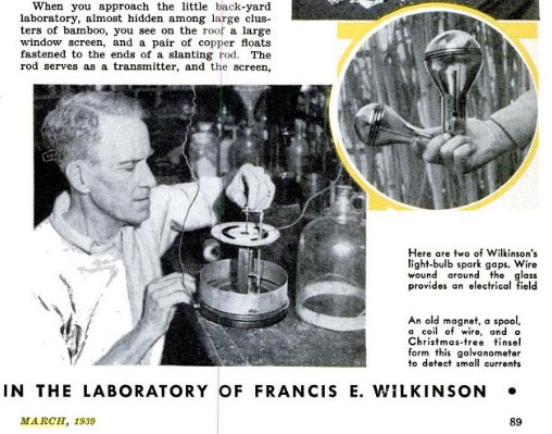
Wilkinson began his researches as a student at London University, in England. Later he came to the United States and settled in California, where for two decades he has worked as a consulting engineer and experimented in his crowded little laboratory. Unbreakable glass tubes, each wound to create a particular electrical frequency; spark gaps made from burned-out light bulbs; a galvanometer employing Christmas tree tinsel -- these are his principal tools.
Tall, spare, easy-going, Wilkinson works methodically to achieve results the full effect of which may not be felt for another generation. He deals with frequencies which stagger the imagination. Your radio programs flowthrough the air on frequencies in the 500,000-1,500,000 range. This man has knocked carbon out of natural gas with an 80 MHz frequency. Just as easily, he treats walnut oil with 100 MHz.


Three years ago he thought he was beginning to plumb a few secrets of the effects of electricity on matter. About that time he turned his attention to round-the-world airplane flights. "Since petroleum products are not easily available in all countries", he reasoned, "the world must have a universal motor fuel, one easily manufactured anywhere."
He went to work to find a motor fuel which could be created from fruits or vegetables. He treated decayed fruit with electricity, produced both alcohol and lubricants. Then he discovered that by adding products obtained from sour cottonseed oil to the alcohol, he had an efficient motor fuel. For good measure, among the byproducts was a material which looks, smells, and bounces like crude rubber. He submitted several pieces to a Los Angeles laboratory, and in a few days received a sheet of refined rubber.
"Decayed vegetables will supply the alcohol", he told me. "Alcohol may be easily combined with the carbon radical from other oils, gums, and resins by high-frequency treatment. This motorists and airplane pilots need not depend upon oil wells for their fuel.
Five years Wilkinson labored, pouring streams of high-frequency "juice" through waste natural gas and tap water. Eventually he hit the proper combination, and got alcohol. Now he's using gas rich in hydrocarbons in an effort to achieve a high-grade alcohol, one which will provide the basis for a high-test motor fuel.
So with old newspapers -- "That's wood, you know" -- and dried potato peelings, rich in starch and several other useful chemicals. he showed me a jar containing a messy paste. It smelled like fragrant wild flowers. "Perhaps", he hazarded, "waste paper one day will provide power for our engines."
On the day of my visit, Wilkinson was answering a hurry-up call from an oil company to find some way of making a sulfur-laden crude fit for use. For two hours he submitted a container of natural gas to an electronic bombardment, 80 MHz. Then he passed the gas through the black crude, which was itself undergoing a 150 MHz treatment. Finally he added salt water to the oil, settled out the water, evaporated the liquid. By "busting " the sulfur compound, he drove free sulfur into the water and recovered it as a small pile of gleaming yellow brimstone. In a half day he changed unusable crude into a lower-gravity oil which could be easily refined.
Standing beside Wilkinson, you can see matter actually change under the electronic bombardment. It looks very simple, yet the process represents a lifetime of cut-and-try experiments. Two tall coils generate the high frequencies. The burned filaments in the discarded light bulbs which have been wound with small wire to create a magnetic field, serve as spark gaps. High-frequency currents from this apparatus pulse through the coils of the tubular vessels in which he treats his raw materials.
Peculiar discoveries attend his researches. For one experiment, he placed a copper electrode in a flask through which high-frequency current was conducted to a liquid. The liquid vaporized and passed through a second flask into a graduate, where it condensed. A quantity of metallic copper collected at the bottom. No heat had been generated, yet somehow the metal was transmuted through vapor and condensed again. On another occasion, he distilled and treated a quantity of carbon tetrachloride, which ordinarily will not burn. Yet after bombarding it with ultra-short waves, it became highly inflammable. Why? Wilkinson cannot say.
When you approach the little backyard laboratory, almost hidden among large clusters of bamboo, you see on the roof a large window screen, and a pair of copper floats fastened to the ends of a slanting rod. The rod serves as a transmitter, and the screen, 36 inches away, as a receiver. With this setup, he transmitted enough power through the air to light a neon lamp in the room below.
This backyard experimenter labors without pay because he hates war, and hopes that his experiments may help provide enough raw materials for the world so that nations will cease going to war over them.
Improvements
relating to the Desulphurisation of Oils of Mineral
Origin
GB 686529
GB 686529
PATENT SPECIFICATION
Inventor: FRANCIS EDWARD WILKINSON
Abstract -- Oils of mineral origin, particularly cracked oils, are desulphurized by subjecting them to the action of hydrogen or ozone, produced in an oscillating magnetic field and to the action of a mixture of hydrogen and oxygen produced by the electrolysis of an acid or alkaline electrolyte. In Fig. 1, the oil in tank 1 (which oil may contain fractions ranging from gasoline to gas oil or may contain gasoline and kerosene only, and may be produced by high pressure cracking) is passed into an agitator 2 where it is treated with alcoholic caustic soda. The mixture is stratified in settling tank 4 and the lower layer, comprising alcoholic caustic soda, gummy constituents from the oil and some sulphur compounds from the oil, is freed from alcohol in still 5, the alcohol vapours being passed to condenser 6 and the condensed alcohol being returned to tank 3 for reuse. The upper layer of oil from tank 4 is passed to tank 7 (see also Fig. 2) which contains an aqueous acid or alkaline solution 8, preferably aqueous caustic soda, the oil forming an upper layer 9. Within tank 7 are a lead plate electrode 12 and a copper or other metal wire mesh screen electrode 14, the two electrodes being connected by leads 15 to a source of direct current so that electrolytic hydrogen and oxygen is produced in tank 7. In addition, air or hydrocarbon gas or vapour is introduced through pipe 18 and, after passage through an oscillating magnetic field in tube 17, with resultant conversion to ozonized air or hydrogen respectively, is fed into tank 7 through pipe 16 and perforated spiral pipe 11 (see also Fig. 3). Tube 17 is provided with two wire coils 19, 20, one inside and one out, and one end of each of these coils is connected to a high voltage, high frequency electric oscillator. Vapours escaping from outlet 10 of tank 7 are passed through a condenser for the recovery of oil, then in turn through caustic soda solution and lime, and finally recycled to tube 17. Oil layer 9 is drawn off and fractionated.

PROVISIONAL SPECIFICATION
This invention relates to the desulphurisation of petroleum oils more particularly but not exclusively distillates thereof, for example, distillates produced in tile eracking of petroleum oils.
A specific example of a distillate produced by cracking has a specific gravity of 47.1 Baume, American Petroleum Institute, an initial boiling point of between 2040 to 210 F., and an end boiling point of approximately to 408 F. In appearance the distillate is dark reddish brown and it contains varying quantities of sulphur depending upon the locality from where the petroleum is obtained. In a known practice of treating this distillate for the purpose of loweriun the sulphur content and decolourizing it, the sulphur content is reduced to four-tenths of 1% or lower. Sulphuric acid and caustic soda treatment is employed to accomplish this followed by a doctor solution treatment. These treatments require considerable expensive apparatus and the process itself takes considerable time, usually requiring in the neighbourhood of twenty-four hours to complete. After being treated the product is mixed with either easing head gasoline or straight 86 run gasoline to bring down the initial boiling point and to reduce the sulphur content to less than one-tenth of 1% to meet specifications of first structure gasoline and at the same time provide a suitable gasoline that can be " leaded " by treatment with tetra ethyl lead.
It is an object of this invention to provide a simple method requiring a much shorter time than the common acid process and which is made possible by the use of nascent hydrogen or ozone instead of sulphuric aeid, which are non-corrosive to the apparatus and which are very cheap to produce as compared with the mnaterials used in other processes. The invention comprises a process of desulphurising petroleum oils wherein nascent hydrogen or ozone passes through a body of oil to be desulphurised in a tank or still which also contains an acid or alkaline electrolyte having therein electrodes supplied from a source of direct current.
Preferably the nascent hydrogen or ozone is produced as the case may be by passage of a natural or other hydrocarbon gas or air through a reaction tube while being subjected to the action of an oscillating electromagnetic field.
In carrying out the invention according to one mode the distillates to be treated may be what are commonly known as processed heavy pressure distillates and kerosene distillates from cracking plants, all of which may be termed raw untreated gasoline stock hereinafter termed stock.
The stock may first be agitated and washed in alcohol in which has been dissolved 2% to 5% of sodium hydroxide to remove gums and some of the sulphur compounds. The washing liquid is separated from the stock and distilled for the recovery of the gums which are utilisable as a base for furniture and other polishes.
The alcohol distilled from the gums can be used again for treating another quantity of stock.
Natural or other hydrocarbons gas is subjected to the action of an oscillating magnetic field by passage of the gas 8 through a reaction tube. The tube is surrounded by a coil wound thereon and a coil is also located in the tube and one end of each coil is connected to an oscillator external to the tube. The voltage 90 employed is from 500 to 100,000 volts at a frequency of from 1 to 9 megacycles.
This treatment results in the production of nascent hydrogen.
Alternatively air may be passed through the tube and similarly treated resulting in the production of ozone.
The stock preferably treated as above 6 referred to is contained in a treating tank or still which also contains an aqueous acid or alkaline solution, for example a 10% solution of sodium hydroxide.
Alkaline solutions are more suitable although acid solutions can be employed with certain oils.
The nascent hydrogen or ozone from the reaction tube is introduced into the treating tank by means of a spirally 16 coiled pipe perforated on its underside and immersed in the liquid therein so that the gas flows in streams into the solution and bubbles upwardly therethrough and then through the oil above it.
The electrode of lead is located in the solution, on or near the bottom of the tankl and is connected to the positive or negative pole of a source of direct electric eurrent and a copper wire mesh screen serves as the other electrode. The screen has suitable stiffening means and is electrically insulated from the treating tank and the lead plate, and is located above the spirally coiled pipe at approximately the contacting surfaces of the oil and the solution. When a source of direct current is connected to the electrode electrolysis of the solution is produced as will hereafter be more explicitly referred to.
The copper wire mesh screen enables the gases from the spirally coiled taube and the solution to pass upwardly through substantially the whole body of oil to he treated and the spirally coiledl tube imay serve as a support for the screen whichi may he of other metal than copper.
The solution is agitated by the gas flowing thereinto from the spirally coiled perforated pipe and may therefore emulsify the oil if escape of gas from said tube is too rapid. This however can be prevented by controlling the flow of gas by providing a valve in the pipe line connecting the reaction tube to the spiral pipe. In operation assuming that natural gas is passing into the reaction tube, the nascent hydrogen produced combines with sulphur in the oil to form sulphuretted hydrogen. Lead sulphide or lead sulfate may be preeipitated on the lead plate which must be washed off the plate from time to time. The direct current passing through the solution dissociates the hydrogen and oxygen and the hydrogen passing upwardly through the oil hydrogenates it at low temperature and pressure, the oxygen combining with sulphur in the oil to form sulphur dioxide and with tile lead of the lead plate to form lead oxide.
The vapour and gases from the tank or still may be collected and pass through a condenser for the recovery of oil, the fixed gases being recirculated through the reaction tube together with an amount of make up hydrocarbon gas found to be necessary. The oil after desulfurisation and hydrogenation is drawn off from the tank or vessel, and introduced into a distillation apparatus wherein it is fractionated in a known manner.
In the case of the production of ozone in the reaction tube, the ozone combines with sulphur in the oil in the tank or still to form sulphur dioxide gas. The oil will be hydrogenated by the hydrogen produced by the electrolysis of solution in the tank or still.
COMPLETE SPECIFICATION
This invention relates to the desulphurisation of oils of mineral origin more particularly but not exclusively distillates thereof for example distillates produced from of petroleum oils.
A specific example of a distillate produced by cracking petroleum has a sp. gravity of 47.1 Baume, an initial boiling point of between 204 to 210 F and an end boiling point of approximately 396 to 408 F. In appearance the distillate is dark reddish brown and it contains varying quantities of sulplhur depending upon the locality from where the petroleum is obtained. In a known practice of treating this distillate for the purpose of lowering the sulfur content and decolourizing it the sulphnr content is reduced to four-tenths of 1% or lower.
Sulphburie acid and eaustie soda treatment is employed to accomplish this followed 115 Ries, the distillates rising above the solution.
The distillates rise to the top of the settling tank and there is a residue of bottoms on the bottom of the tank which contain some of the sulphur compounds and sludges. The lower part of the liquid in the settling tank is run off into a still and the alcohol is recovered by distillation, being condensed in a condenser 6, whereupon it is reintroduced into the tank 1 so as to be available for utilization in treating another quantity of stock.
The residuums which collect in the bottom of the still 5 can be utilised as a base for furniture and other polishes.
The distillate in the settling tank is run by the pipe 16a into a treating tank or still 7 which contains an aqueous acid or alkaline solution 8 (see Fig. 2). the distillates being indicated by,the reference numeral 9. Thus solution 8 may be a 10% solution of sodium hydroxide. Alkaline solutions are most suitable although 10% acid solutions may be employed with certain distillates, The tank has a vapour outlet and within the tank is a spirally coiled pipe 11 (see also Fig. 3) perforated on its underside and positioned so that it is in the solution of sodium hydroxide. The tube is connected externally of the tank or still to a tubular reaction chamber 17 (hereinafter particularly described) and there are also located in the still an eleetrode of lead 12 which is in the solution and is supported above the bottom of the tank by a plate 13 of electrical insulating material. Above the spirally coiled pipe there is supported a copper or other metal wire mesh screen 14 which is also electrically insulated from the treating tank in any suitable manner the screen being positioned so that it is in the solution at approximately the contact surfaces of the distillate and sodium hydroxide solution.
The screen may be provided with stiffening means and the screen 14 and the lead plate 12 constitute electrodes which are connected externally of the tank or 115 still by conducting wires 15 to a source of direct current.
The spirally coiled pipe 11 is connected by an extension 16 to a tubular reaction chamber 17 which may be of 120 glass or other refractory electrical insulating material and which has a gas inlet 1.8 at the other end for supply of hydrocarbon gas thereto. The chamber is surrounded by a coil of wire 19 wound 12.5 thereon and within the tube is another coil of wire 20 and the one end of each coil is connected by a lead to an oscillator (not shown) external to the chamber.
The voltage employed is 500 to 100,000 by a Doctor Solution treatment. These treatments require considerable expensive apparatus and the process itself takes considerable time usually requiring in the neighbourhood of twenty-four hours to complete. After being treated the product is mixed with either casing head gasoline or straight run gasoline to bring down the initial boiling point and to reduce the sulphur content to less than one-tenth of 1% to meet the State of California specifications of gasoline and at the same time provide a suitable gasoline that can be "leaded" by treatment with tetra ethyl lead.
It is an object of this invention to provide a simple method requiring a much shorter time than the common acid process and which is made possible by the use of hydrogen or ozone instead of sllphuric acid, which are non-corrosive to the apparatus and which are very cheap to produce as compared with tb e materials used in other proceesses.
The invention comprises a process of desulphurising oils of mineral origin wherein the oil is subjected to the action of hydrogen or ozone produced in an oscillating magnetic field a mixture of hydrogen and oxygen produced by the electrolysis of an acid or alkaline electrolyte.
Preferably the hydrogen or ozone is produced as the case may be by subjecting a natural or other hydrocarbon gas or air to the action of an oscillating electromagnetic field.
Referring now to the accompanying drawings : Figure 1 is a diagrammatic view of apparatus employed in carrying out the process, Figure 2 is a diagrammatic view in sectional elevation showing in greater detail means for carrying out one part of the process, and Figure 3 is an inverted plan of a detail.
In carrying out the invention according to one mode the distillates to be treated may be what are commonly known as high pressure cracking distillates usually containing fractions ranging from gasoline to gas oil or containing gasoline and kerosene only, hereinafter termed stock.
Stock from a tank 1 is introduced into all agitator 2 with an alcohol such as ethyl alcohol denatured with methyl alcohol, from a tank 3 in which 2 to 5% sodium hydroxide is dissolved. The solution and stock are thoroughly agitated and as a result the solution extracts some of the gummy constituents and sulphur compounds from the stock. After said agitation the mixture is introduced into a settling tank 4 wherein the mixture stratifies, the distillates rising above the solution.
The hydrocarbon gas through a tubular reaction chamber of refractory electrical insulating material, surrounded by a coil of wire wound thereon and containing another coil of wire therein, one end of each coil being connected to an oscillator supplying 500 to 100,000 volts at a frequency of 300 to 500 megacycles per second.
...
at 686,529 volts at a frequency of from 1/2 to 9 megacycles per second and when hydrocarbon gas flows through the chamber hydrogen is produced and earbon is deposited in the chamber. Natural or other hydrocarbon gas can be employed and an analysis of California natural gas which has been found satisfactory is as follows:
Per cent. Methane , 85.3 -- Ethane, 11.6 -- Nitrogen , 1.9 -- Carbon dioxide , 7 -- Oxygen , 5
Instead of hydrocarbon gas, hydrocarbon vapour may be employed produced by heating a liquid or solid hydrocarbon to vapourise it before passae through the tube, it being understood that an appropriate frequency will be employed for dissociation of the hydrocarbon employed.
Alternatively air may be passed through lthe tube and similarly treated and this results in the production of ozone.
Hydrogen or ozone from the reaction chamber passes into the treating tank through the spiral coil pipe 11 and the gas flows downwardly through the perforations thereof into the solution and bubbles upwardly therethrough and through the distillates above the solution.
Since a source of direct current is connected to the electrodes 12 and 14 electrolysis of the solution proceeds, the copper wire mesh screen enabling the gases discharging from the spirally coiled tube and the electrodes to pass upwardly through substantially the whole body of the distillates being treated. Thus the solution is agitated by the gas flow and emulsification of the oil may take place if escape of gas from the tube is too rapid.
This however can be prevented by controlling the flow of gas for example by providing a valve 21 in the pipe extension 16 of the spirally coiled tube to the reaction chamber.
In operation, assuming that natural gas is passing into the reaction tube and being dissociated therein, the hydrogen produced combines with sulphur in the oil to form sulphuretted hydrogen. Owing to the agitation of the solution and of the distillates by the gas flow, sulpuretted hydrogen may come into contact with lead plate 12. Thus lead sulphide may be formed on the lead plate and must be washed off the plate from time to time.
The direct current passing through the solution liberates hydrogen and oxygen; the hydrogen passing upwardly through the oil hydrogenates it at low temperature and pressure and the oxygen conmbines with sulphur in the oil to form suilphur dioxide, with the lead of the lead plate 12 (which it reaches through agitation of the solution) to form lead oxide, and with the above-mentoned lead sulfide to form lead sulfate on the lead plate. The vapour and gases from tile tank or still may be collected and passed through a condenser for the recovery of oil, the fixed gases. after passage first through caustic soda solution and then through lime, being recirculated through the reaction tube together with an amount of make up hydrocarbon gas found to be necessary.
The oil after desulphurisation and hydrogenation is drawn off from the tank or vessel and introduced into a distillation apparatus wherein it is fractionated in a known manner.
In the case of the production of ozone in the reaction tube, the ozone combines with sulphur in the oil in the tank or still to form sulphur dioxide gas. The oil will also be lhydrogenated by the hydrogen produced by the electrolyis of the solution in the tank or still.
EXAMPLE I
Apparatus: As illustrated in the accompanying drawings.
Stock: Pressure distillate from cracking process. Specific gravity 47.8' Baume at (i} F. Sulphur content.0J92%.
Alcoholic caustic soda solution:
Caustic soda in ethyl alcohol. 10b
Screen: Copper.
Hvdrogen: Produced fromn California Natural gas.
Magnetic field: 500 to 100,000 volts.
Frequency to 9 megacycles per second.
Electrolysis: Direct current.
Hydrogen: Pressure flow through treating tank 7 substantially 4" water pressure.
Sulphur content: After treatment of 110 stock.03 5%,.
Gasoline content: Increase 15%.
EXAMPLE II
Apparatus: As illustrated in the accompanying drawings. 115 Stock Heavy sulphur crude. Specific gravity 16- Baume. American Petroleum Institute at 61V F. Gasoline (content about gas oil content approximatelv 20. asphlalt content 40), sulphur content 4.5 to 6j.0 kerosene, lubricating oil and wax-content 14 to 15.5%.
Alcoholic caustic soda solution:,, caustic soda in ethyl alcohlol.
Screen: Copper. 125 Gas: Ozonised air pressure flow through treating tank 7 substantially 4" water pressure.
the hydrocarbon gas through a tubular reaction chamber of refractory electrical 25 insulating material, surrounded by a coil of wire wound thereon and containing another coil of wire therein, one end of each coil being connected to an oscillator supplying 500 to 100,000 volts at a frequency of 300 to 500 megacycles per second.
Process
and apparatus for treating hydrocarbons
GB697224
GB697224
1953-09-16
Inventor(s): WILKINSON FRANCIS EDWARD + (WILKINSON FRANCIS EDWARD)
Classification: - international: C10G15/00; C10G9/24 - European: C10G15/00; C10G9/24IDT
Abstract -- Apparatus for treating hydrocarbon gas to produce lighter products by dissociation or cracking comprises a tube 1 of glass or other electrical insulating material having an inlet 2 for supplying gas to be treated and an outlet 3 for the treated gas. A coil of wire 5 extends into the tube and is sealed in the side wall or end closure of the tube and another coil of wire 4 surrounds the tube. One end of the coil 4 and one end of the coil 5 are connected by terminals 6 and 7 to a high frequency oscillator, Fig. 2 (not shown), whereby an electromagnetic field is applied to the gas passing through the tube. The high frequency oscillator contains a number of tuned circuits which produce a heterodyne effect which is stated to assist the process. The frequencies used range from 25 to 100 Kc/s. and the process does not require a high temperature and pressure. Finely divided carbon is deposited in the tube.

The invention finds particular application to the treatment of hydrocarbon gas, for example, natural gas, or coal gas, and the object is to produce lighter gaseous products by an apparatus which does not require high temperature and pressure for its successful operation.
According to the invention apparatus for treating hydrocarbon gas or vapour to produce lighter products by dissociation, comprises a reaction tube or vessel through which the gas or vapour is passed and in which it is subjected to the action of a high frequency electromagnetic field, the said tube being surrounded by an external coil and containing another coil and the said coils being connected to a high frequency oscillator.
In the case of treatment of liquid or solid hydrocarbons, the solid or liquid may be preheated to convert it into vapour before it flows into the tube or vessel to be subjected to the action of the field.
Apparatus (Figure 1) for the treatment comprises a tube 1 of glass or other electrical 60 insulating material having an inlet 2 at one end for supplying to the tube the gas to be treated and an outlet 3 at the other end for the treated gas, the tube being sealed from communication with the exterior. 65 The tube is surrounded by a coil of wire 4 which may have an insulating covering and another coil of wire 5 extends into the tube from one end thereof, the wire 5 being sealed in the side wall or an end closure of the tube. 70 One end of the coil 4 and one end of the wire 5 are connected by terminals 6 and 7 to a high frequency oscillator whereby a tuned high frequency electromagnetic field is applied to the gas or oil vapour passing 75 through the tube.
A circuit of an oscillator suitable for use with the treating apparatus above described comprises a transformer 20 having an input voltage of 110 volts at a frequency of 50 or 80 cycles per second. Various tapping points 20a are provided on the secondary for tapping off various voltages up to the full value. The secondary winding of the transformer is connected to a plurality, for example, four Oudin coil resonator circuits 21, 22, 23, 24, each having respectively ...
The invention is based upon the fact that all atoms have a resonant high frequency electromagnetic vibration to which they will respond. It is by the application of this resonant frequency to a hydrocarbon compound, that hydrogen is dissociated from its bond with carbon.
The invention finds particular application to the treatment of hydrocarbon gas, for example, natural gas, or coal gas, and the object is to produce lighter gaseous products by an apparatus which does not require high temperature and pressure for its successful operation.
According to the invention apparatus for treating hydrocarbon gas or vapour to produce lighter products by dissociation, comprises a reaction tube or vessel through which the gas or vapour is passed and in which it is subjected to the action of a high frequency electromagnetic field, the said tube being surrounded by an external coil and containing another coil and the said coils being connected to a high frequency oscillator.
In the case of treatment of liquid or solid hydrocarbons, the solid or liquid may be preheated to convert it into vapour before it flows into the tube or vessel to be subjected to the acgtgionofhe field.
The invention also comprises a high frequency oscillator in which frequencies are heterodyned.
Referring now to the accompanying drawings:Fig. 1 is a reaction tube for treating a mixture of hydrocarbon gases or vapours; and Fig. 2 is a diagram of a high frequency circuit that may be employed for carrying out the treatment and capable of being tuned to the necessary frequency.
In carrying out the invention as applied to the treatment of natural gas consisting principally of methane and ethane the apparatus (Figure 1) for the treatment comprises a tube 1 of glass or other electrical insulating material having an inlet 2 at one end for supplying to the tube the gas to be treated and an outlet 3 at the other end for the treated gas, the tube being sealed from communication with the exterior.
The tube is surrounded by a coil of wire 4 which may have an insulating covering and another coil of wire 5 extends into the tube from one end thereof, the wire 5 being sealed in the side wall or an end closure of the tube.
One end of the coil 4 and one end of the wire 5 are connected by terminals 6 and 7 to a high frequency oscillator whereby a tuned high frequency electromagnetic field is applied to the gas or oil vapour passing through the tube.
A circuit of an oscillator suitable for use with the treating apparatus above described comprises a transformer 20 having an input voltage of 110 volts at a frequency of 50 or cycles per second. Various tapping points 20a are provided on the secondary for tapping off various voltages up to the full value. The secondary winding of the transformer is connected to a plurality, for example, four Oudin coil resonator circuits 21, 22, 23, 24, each having respectively therein a variable condenser, 25, 26, 27, 28, a primary29, 30, 31, 32, having a sliding tap, a secondary 33, 34, 35, 36 and a spark gap 36, 37, 38, 39. One of the terminals of the secondaries a, b, c, d, of a resonator circuit is connected to the external coil above described and the wire extending into the tube is connected to a switching device for connecting any one of the remaining terminals a, b, c, d, to the wire. The spark gaps 36, 37, 38 and 39 are connected in series with their respective coils 29, 30, 31 and 32 so that when the respective capacitors 25, 26, 27 and 28 are charged by the input voltage it breaks down the spark gap to complete the oscillator circuit. When the circuits are adjusted to be almost in resonance a heterodyne effect is produced by the mixture of frequencies and this is an important factor in effecting dissociation or cracking of the hydrocarbon gas or vapour being treated. The frequencies employed may range from 25,000 to 100,000 cycles per second and as will now be understood the process is carried out without employment of high temperature and pressure.
It has been found that treating natural gas containing substantially 86% methane and 14% ethane by the process results in production of 83% methane, 7% ethane and free hydrogen and carbon 10%.
As will be understood the hydrogen which is in a nascent condition or activated after treatment, can be utilised either alone or with the ethane and methane for the hydrogenation of oils. Finely divided carbon collects in the tube which can be removed from time to time and which is utilisable for various purposes in the arts.
As will now be appreciated the invention provides a process for dissociation or cracking of hydrocarbons which operates under low temperature and pressure as compared with prior processes.
Thus the gas or vapour to be treated requires to be only under sufficient pressure for its passage through the apparatus. In the case of treatment of liquid or solid hydrocarbons the temperature will be such as to maintain the liquid or solid in the vapour phase until it has passed through the apparatus, it being understood that subsequent to treatment the vapour is condensed for the recovery of the condensate. The hydrogen gas recovered can be utilised, if desired, for hydrogenation of oils.
http://v3.espacenet.com/publicationDetails/biblio?DB=EPODOC&adjacent=true&locale=en_EP&FT=D&date=19530916&CC=GB&NR=697223A&KC=A
Process
and Apparatus for Treating Mineral or Vegetable Oils for
the Production of Oils of Lower Boiling Point
GB697223
GB697223
1953-09-16
Inventor(s): WILKINSON FRANCIS EDWARD + (WILKINSON FRANCIS EDWARD)
Applicant(s): WILKINSON HIGH FREQUENCY LTD + (WILKINSON HIGH FREQUENCY LIMITED)
Classification: - international: C10G15/00; C11C3/12 - European: C10G15/00; C11C3/12IDT
Abstract -- A process for treating mineral or vegetable oil for the production of oil of lower boiling point comprises passing hydrogen through alcohol and carbon tetrachloride, the liquids being heated so that they evaporate slowly, passing the vapours thus produced through a body of the oil heated so that it evaporates slowly, passing the vapours thus produced over a contact mass, consisting of aluminium, copper, zinc or carbon, while being subjected to the action of a high frequency electromagnetic field and condensing the vapour after its passage over the contact mass. The alcohol and carbon tetrachloride may be employed in the form of a mixture or alternatively the hydrogen may pass in succession through a body of each. The alcohol may be ethyl alcohol or other monohydric aliphatic alcohol. The hydrogen may be produced by subjecting hydrocarbon gas, natural or otherwise, or hydrocarbon vapour to the action of a high frequency electromagnetic field. A mixture of hydrogen and hydrocarbon vapours or gases produced by this method may alternatively be employed. The oils treated may be low grade mineral oils or residuums or distillates thereof, or vegetable oil foots. Specific oils mentioned are crude petroleum, gas oil, mineral lubricating oil, linseed oil, cottonseed oil and coconut oil. In the case of mineral lubricating oil, the condensed product is a lubricating oil of increased film strength and raised pour point, but in the case of gas oil and vegetable oils, the condensed product is a light fuel oil suitable for use in internal combustion engines. The unvaporized residue of oil remaining after treatment is a plastic rubber-like mass. In the Figure, natural or other hydrocarbon gas or vapour is passed through tube 17 of glass or other electrical insulating material. Tube 17 has a wire or conductor 18 therein and is surrounded by a coil of conducting wire 19, adjacent ends of conductor 18 and coil 19 being connected to an electrical oscillator tuned to a frequency sufficient to cause dissociation of the hydrocarbon into carbon and hydrogen. The electrical oscillator circuit may be as described in Specification 697,224, [Group XL(a)]. The carbon is deposited on the inside of tube 17 in the form of lampblack, while the hydrogen formed bubbles through the heated mixture of ethyl alcohol and carbon tetrachloride in vessel 6. Vapours from vessel 6 bubble through the body of heated gas oil or cottonseed oil foots in vessel 1, while vapours from vessel 1 pass up column 11. This column is filled with aluminium, zinc or copper clippings or carbon or charcoal granules and has therein an electric conductor 14 which may be a coil of wire. A coil of conducting wire 15 surrounds column 11 and adjacent ends of conductor 14 and coil 15 are connected to a high frequency oscillator so that a high frequency electro-magnetic field can be produced within the column. Vapours from column 11 pass through condenser 13 and the condensate is collected.
A further object is to produce a rubber like material capable of being vulcanised by the known processes employed for rubber.
The invention comprises a process for treating mineral or vegetable oil for the production of oil of lower boiling point comprising passing hydrogen through alcohol and carbon tetrachloride, the liquids being heated so that they evaporate slowly, passing the vapours thus produced through a body of the oil heated so that it evaporates slowly, passing the vapours thus produced over a contact mass consisting of aluminium, copper, zinc or carbon while being subjected to the action of a high frequency electromagnetic field and condensing the vapour after its passage over the contact mass.
Preferably the hydrogen is produced by subjecting hydrocarbon gas, natural or otherwise, or hydrocarbon oil vapour to the action of a high frequency electro-magnetic field. Alternatively, a mixture of hydrogen and hydrocarbon vapours or gases produced by this method may be employed.
The invention also consists in apparatus for carrying out the process which apparatus is illustrated in the accompanying drawing.
The invention will be particularly described as applied to the production of light fuel from heavy petroleum distillates known as "gas oil" of a specific gravity of 27 Baume or more, a quantity of the "gas oil" being introduced into a treating tank or vessel 1 provided with heating means not shown, whereby the temperature of the gas oil is raised and maintained at a point viz., about 430 F. at which vaporisation takes place slowly.
The upper part of the treating vessel 1 has a closure 2 having an inlet and an outlet connections 3, 4, the inlet connection 3 having a pipe connection 5 to an outlet connmection at the upper part of a second tank or vessel 6
PATENT SPECIFICATION
This invention relates to a process and apparatus for treating mineral or vegetable oils for the production of oils of lower boiling point.
The invention is applicable to mineral oils or residuums or vegetable oils or foots thereof, specific examples of which are crude petroleum, gas oil, petroleum distillates, linseed or cotton seed oils, or mineral lubricating oil. One object of the invention is the production, without the need for high temperatures and pressures, of a light liquid fuel more particularly but not exclusively for use as a light fuel for internal combustion engines in place of the present light fuels employed.
A further object is to produce a rubber like material capable of being vulcanised by the known processes employed for rubber.
The invention comprises a process for treating mineral or vegetable oil for the production of oil of lower boiling point comprising passing hydrogen through alcohol and carbon tetrachloride, the liquids being heated so that they evaporate slowly, passing the vapours thus produced through a body of the oil heated so that it evaporates slowly, passing the vapours thus produced over a contact mass consisting of aluminium, copper, zinc or carbon while being subjected to the action of a high frequency electromagnetic field and condensing the vapour after its passage over the contact mass.
The alcohol may be ethyl alcohol or other monohydric aliphatic alcohol.
In the case of the treatment according to the foregoing statement of vegetable oils, the residue after treatment is in the form of a plastic mass which is capable of being vulcanised by well known processes employed for the vulcanisation of rubber in which case either the plastic mass or light fuel oil or both can be recovered.
In the case of the treatment of the Union Oil Co's paraffin or asphaltic base mineral lubricating oil known under the Registered Trade Mark Triton, the condensate has increased film strength and the pour point is raised.
Preferably the hydrogen is produced by subjecting hydrocarbon gas, natural or otherwise, or hydrocarbon oil vapour to the action of a high frequency electromagnetic field. Alternatively, a mixture of hydrogen and hydrocarbon vapours or gases produced by this method may be employed.
The invention also consists in apparatus for carrying out the process which apparatus is illustrated in the accompanying drawing.
The invention will be particularly described as applied to the production of light fuel from heavy petroleum distillates known as "gas oil" of a specific gravity of 27 Baume or more, a quantity of the " gas oil " being introduced into a treating tank or vessel 1 provided with heating means not shown, whereby the temperature of the gas oil is raised and maintained at a point viz., about 430 F. at which vaporisation takes place slowly.
The upper part of the treating vessel 1 has a closure 2 having an inlet and an outlet connections 3, 4, the inlet connection 3 having a pipe connection 5 to an outlet connection at the upper part of a second tank or vessel 6 ( and also having a downwardly extending pipe 7 which at its lower open end is in the body of gas oil to be treated. The second tank or vessel also has an inlet connection 8 at its upper end which has a downward pipe extension 9, the open lower end of which extends substantially to the bottom of the second vessel 6 into a mixture of ethyl alcohol and carbon tetra-chloride therein.
The mixture is in the proportions of 5 to 10% of the carbon tetrachloride to 95 to 90% of alcohol.
The inlet connection 8 of the second tank or vessel 6 is connected by a pipe 10 to a source of supply of hydrogen which may be produced in a manner hereinafter referred to.
The second tank or vessel is provided with heating means so that the liquids therein slowly evaporate, a suitable range of temperature being 100 to 150 F.
The outlet connection of the treating vessel is connected to the lower end of a dephleg:mating column 11 which is connected at its upper end by a pipe 12 to a condenser 13, which is shown as a Liebig's condenser, to condense the light oil va),uurs nwhich pass out of the column.
The column is of tubular form and has extending centrally theretnhrough an electric conductor 14 which may be a coil of wire which has an extension to the outside of the column. Surrounding the column is a coil of conducting wire 15 and adjacent ends 14a of the conductor 14 and coil 15 are connected to a high frequency oscillator so that a high frequency electromagnetic field can be produced within the column. Frequencies employed range from 10,000 to 10,000,000 cycles. The column 11 is filled with a contact mass consisting of clippings of aluminium, zinc, copper or carbon granules.
The hydrogen for carrying out the process may be produced by the action of a high frequency electrical discharge on natural or other hydrocarbon gas or vapour. The discharge apparatus may comprise a tube 17 of glass or other electrical insulating material having a centrally extending wire or conductor 18 therein and a coil 19 of conducting wire surrounding the tube on the outside, adjacent ends of the conductor and coil being connected to an electrical oscillator tuned to a frequency sufficient to cause dissociation of the carbon and hydrogen.
Lamp black collects in tube 17. In operation, small sparks pass through the gas from the conductor 18 and the outer coil 19 glows with violet light. The glow is clearly visible in the dark but not visible in daylight.
The gas is therefore subject to an electrical discharge and possibly also to the effects of ultra-violet and other rays.
We have found that frequencies in the range of 750,000 to 8,000,000 are required depending on the gas or vapour employed.
When the process is in operation hydrogen passes into the tank or vessel 6 and bubbles through the heated mixture of alcohol and carbon tetrachloride therein. It is not essential that the hydrogen flow through a mixture of alcohol and carbon tetrachloride as it may flow through a body of each liquid in succession provided each liquid is heated so that it evaporates slowly and the vapours produced pass together into the vessel 1. It is believed that the hydrogen readily combines with the oxygen of the alcohol forming water and a low boiling point hydrocarbon which wvil readily combine with fractions of the "gas oil" under treatment. It is believed that low boiling point hydrocarbons may also be produced by reaction of the hydrogen with part of the carbon tetrachloride. The vapours produced in the second tank or vessel pass into the treating vessel 1 where they bubble through the gas oil in the treating vessel, and it is believed that the low boiling point hydrocarbons combine with fractions of the gas oil. The vapours from the vessel 1 pass upwardly through the dephlegmating column to the condenser, the condensate from which is the light fuel desired to be produced. The boiling point range of the fuel is from 90 to 250 F., and its specific gravity range is from 28 to 95 32 Baume.
Any fixed gases which escape from the condenser may be recirculated through the apparatus for the utilisation of hydrogen therein. In passing the carbon tetrachloride vapour through the dephlegmator in contact with the aluminium clippings, aluminium chloride is produced which flows back into the gas oil under treatment and promotes and increases the production of lower boiling point fractions.
In the case of treatment of cotton seed oil foots, natural or other hydrocarbon gas or vapour is passed through the discharge apparatus 17 where it is subjected to the action of moderate high frequency electromagnetic field of from 50,000 to 250,000 cycles which may be produced by means of four step up induction coils connected to give high frequency current. The induction coils may be excited by means of a 0.125 KVA step down transformer converting 110 v A.C. to 3, 6, 11, 17 and 20 volts respectively by tappings from the secondary of the transformer. The discharge frequency is tuned by means of suitable condensers to approximately the frequency required for dissociation of hydrocarbon gas or oil vapour. The power employed in experiments was about 125 to 150 watts. The induction coils may be Oudin coils and the circuit as described and illustrated in Application No. 21671/49, (Serial No. 697,224).
The treated gas passes through a mixture of alcohol and carbon tetrachloride in the tank or vessel 6 or first through one of the liquids and then through the other. A suitable mixture is 90% alcohol and 10% CC1 but other proportions may be used. The vessel 6 is heated to keep the liquid warm but the temperature must not be raised to boiling point.
The vapours from the tank or vessel 6 then pass into the tank or vessel 1 which contains a body of cotton seed oil foots to be treated.
The vessel 1 is heated to reduce the viscosity of oil therein.
The vapours pass from the vessel 1 upwardly through the dephlegmating column which contains aluminium and /or zinc clippings and granular carbon or charcoal.
From this column the vapours pass to a condenser from which fixed gases are recycled through the apparatus after passing through an ice condenser.
The temperature of the liquid in the vessel 6 is maintained at from 65 to 70* C., and in the treating tank 1 at 1800 0., and treatment is carried out for approximately two hours. The CO14 passing through the aluminium or zinc or both forms chlorides which flow into the oil and promote the formation of low boiling point products.
It has been found that the condensate is suitable for use as a motor fuel and a spongy rubber-like residuum which can be vulcanised is produced in the treating vessel 1. Various other vegetable oils may be similarly treated, with the following results. Coconut oil after treatment as above deseribed was liquid when the vessel had cooled to normal temperature and a condensate suitable for use as motor fuel was produced.
Linseed oil similary treated changed to a soft spongy mass which was plastic at normal temperature but softened on heating and could be treated to produce a rubber-like material which could be vulcanized, the condensate being suitable for use as motor fuel. The products can also be produced from other vegetable oils and low grade nineral oils and distillates therefrom that have little or no commercial value and the process is carried out at atmospheric pressure or substantially so and at low temperatures as compared with prior processes.
Process
and Apparatus for the Extraction of Gold from its Ores
GB658638
GB658638
1951-10-10
Inventor(s): WILKINSON FRANCIS EDWARD + (WILKINSON FRANCIS EDWARD)
Applicant(s): WILKINSON HIGH FREQUENCY LTD + (WILKINSON HIGH FREQUENCY LIMITED)
Classification: - international: C22B11/08 - European: C22B11/08
Abstract -- A process for extracting gold from gold ore pulp or tailings comprises mixing the latter with a solution of cyanide, passing ozone through the mixture and subjecting it to the action of a high frequency electromagnetic field. The mixture may also contain hydrated lime. The process may be carried out in the apparatus shown in the drawing in which a vessel 1 contains the reaction mixture and is heated to 110 F. on a water bath 2. Ozone is produced by passing air through electrolyzer tube 8 and is introduced into the mixture through tube 3. The high-frequency electromagnetic field is applied between electrodes 4 and 5. Evaporated cyanogen gas passes through tube 6 to vessel 7 in which it is absorbed in a solution of sodium chloride which may then be used for treatment of a further batch of pulp or tailings.

This invention relates to the extraction of gold from its ores more particularly gold contained in gold ore pulp or tailings, the object of the invention being to provide an improved process and apparatus for such extraction.
The invention has particular relation to processes of the kind in which the pulp or tailings from which gold is to be extracted is treated with cyanide solution, the primary object of the present invention being to reduce the time required for treatment.
According to the invention gold ore pulp or tailings is mixed with a cyanide solution and ozone is passed therethrough whilst the mixture is subjected to the action of a high frequency electro-magnetic field.
The cyanide solution may be potassium or sodium cyanide.
'The- invention will be described with reference to the accompanying diagrammatic drawing and according to one mode, there is added to gold ore pulp, potassium cyanide solution in which thepotassium cyanide content is 2.66 lbs. per ton of solution, the solution also having added thereto hydrated lime to the extent of 1110 grams per 100 grams of solution for neutralising acid in the ore or pulp. Three pints of the cyanide solution are added for each pound of pulp. The foregoing mixture is placed in a closed treating tank or vessel 1 supported on 'a water-bath 2 and heated by the latter to a temperature of 11W F., and ozone which promotes conversion of the gold to cyanide is introduced through a tube 3 extending downwardly to near the bottom of the vessel so that it escapes from the lower end of the tube into the liquid mixture and bubbles upwardly therethrough so as to agitate the mixture.
The mixture in the vessel is also subjected to the action of a high frequency electromagnetic field by means of metal electrodes one of which 4 projects into the mixture in the vessel and the other is a plate 5 secured within the bottom of the vessel.
It has been found that some cyanogen gas is liberated in the vessel 1 and it is allowed to escape from an outlet connection 6 of the vessel into a pipe which extends downwardly to near the bottom of a second vessel 7 which contains a saturated solution of sodium chloride, this vessel being open to atmosphere.
The cyanogen gas is absorbed by the salt solution and the latter can be used for cyaniding another quantity of pulp as will hereafter be explained.
The ozone or nascent oxygen may be and preferably is produced continuously by passing air through an electrolizer tube 8 during which the air is subjected to the action of a high frequency electromagnetic field, the electfolizer tube having an outlet 9 from which a pipe extends downwardly into the liquid in the vessel 1. After-treatment of the pulp for one hour in the vessel 1, the treated pulp containing gold cyanide in solution is removed from the vessel 1 and passes into a settling tank and allowed to remain therein until the tailings have settled to the bottom of the tank. The cyanide solution is then removed form the settling tank and treated to precipitate the gold therefrom in known manner. For example zinc or aluminium filings may be employed to obtain precipitation of the gold and in the case of zinc the latter can be parted froaii the gold by sulpliuic acid.
It- has been found that by treatment of a batch of pulp as above described and for the period specified 70 % of the gold content of the batch can be recovered by subsequent precipitation. With a shorter period of treatment of half an hour the recovery of gold amounted to 36.311% of the gold content of the batch.
As above pointed out the salt solution containing eya-nogen gas in tank or vessel 7 can be used for treating another and subsequent batches of pulp or tailings and this can take place in another vessel or tank to which the salt solution is supplied for mixing with the pulp or tailings. Cyanide solution is then added and, the mixture introduced into the vessel where it is treated in the same manner as the first batch. The treatment of pulp as tailings with the salt solution containing cvanogen gas results in the production of goId chloride or gold-cyanide or both from which the gold can be precipitated for example in the manner indicated above for the first batch.
It has been found that the treatment of a batch of pulp as just described for a period of one hour resulted in recovery by subsequent-precipitation of 31.6 % of the gold content of the batch and that if the treatment was extended to one and one half hours the recovery of gold increased to 34 %.
Improvements
relating to Aerial Devices
GB680280
GB680280
1952-10-01
Inventor(s): WILKINSON FRANCIS EDWARD + (WILKINSON FRANCIS EDWARD)
Applicant(s): WILKINSON HIGH FREQUENCY LTD + (WILKINSON HIGH FREQUENCY LIMITED)
Classification: - international: H01Q21/00 - European: H01Q21/00IDT
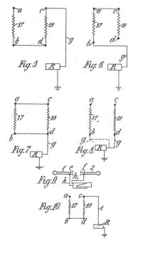
Abstract -- An aerial device comprises a pair of tubular members 1, 2, in axial alignment and insulated from each other, each communicating at its outer end with a hollow sphere of the same material 5, 6, and having extending therethrough at least one rod or bar 14, 16, of ferromagnetic metal surrounded by a coiled insulated conductor 17, 18 having an extension coiled in opposite directions about the end portions of the poles of one of a pair of permanent magnets 11, 12, and having means for connecting the coils to a transducer. The magnets 11, 12 are preferably horse-shoe magnets located transversely in a casing of insulating material to the opposite sides of which end flanges 3 and 4 on the tubes 1 and 2 are secured. The magnets have their like pole-tips facing each other but spaced apart. In the preferred embodiment the ends of the rods 14 and 16 are bent over and flattened so that they rest the one against the south pole of one magnet and the other against the north pole of the other magnet. The insulated wires 17 and 18 are coiled round the end portions and the polepieces of the magnets and then brought out to terminals a, b, and c, d, as shown diagrammatically in Fig. 3. Further terminals c, f are attached to the tubes 1 and 2 and the rods and coils are held inside the tubes by insulating material 19a, 20a. The insulating central case may be pivoted about a horizontal axis in a support capable of rotation about a vertical axis so that the directivity of the device may be varied, Fig. 4 (not shown). The aerial may be connected to a receiver in various ways. For example, terminals b and d may be joined and c connected to the feeder; or a and c may be joined and b connected to the receiver; or the two insulated conductors may be connected in parallel or alternatively to the receiver, Figs. 5, 6, 7 and 8 (not shown). For television reception the vision signals may be derived from terminals e and f and the terminals a, b, c and d, connected in any one of the ways previously mentioned, may be used to provide the sound signals, Figs. 9 and 10 (not shown).


The invention has for its primary object an improved aerial device whereby better reception and greater effective radius can be attained.
A further object is to provide an improved mounting whereby the aerial device is rendered directional.
A further object is to provide an improved aerial device which provides for alternative ways of connecting it to a radio receiving set.
According to the invention an aerial device comprises a pair of tubular members of non-magnetic conducting material in axial or substantially axial alignment but insulated from each other and each communicating at its outer end with a hollow sphere of said material, each tubular member having extending therethrough at least one rod or bar of ferro-magnetic metal surrounded by a coiled conductor insulated from the tubular member and each conductor having an extension eoiled in opposite directions about the end portions of the poles of one of a pair of permanent magnets, and means for connecting the coils to a radio receiver or transmitter.
It is not essential that each rod or bar be unitary as they may each be laminated or comprise a bundle of wires of ferromagnetic material, and the term rod or bar when hereinafter employed is to be interpreted as including such variations.
Referring now to the accompanying drawings:Fig. 1 is a part sectional plan of an aerial device according to the invention, the section being taken on the line I-I Fig. 2; 50 Fig. 2 is a transverse section of Fig. 1 taken on the line II-II of that Figure; Fig. 3 is a diagrammatic view to show the wiring more clearly, the terminals and connections of the wiring thereto; Fig. 4 is an elevation showing the device supported on a mounting; Figs. 5, 6, 7 and 8 are diagrams showing various ways by which the device can be connected to a radio receiver or wireless set; and Figs. 9 and 10 are diagrams showing how the device can be connected to a television receiver.
In carrying out the invention two tubes 1, 2, are provided of non-magnetic electrical conducting material which may be brass or copper, each tube having its inner end provided with a flange 3, 4. The outer end of tube 1 communicates with the interior of a hollow sphere 5 which is of the same metal as the tubes and the outer end of tube 2 communicates with the interior of hollow sphere 6 also of the same metal as the tubes. Each tube 1, 2 and its sphere 5, 6 are shown in the drawings as being integral with each other but may be manufactured independently and secured together as by brazing and if desired the spheres may each comprise hemispherical sections also secured together by brazing. The tubes are secured as by screws 7, 8, extending through the flanges 3, 4, to opposite sides 9, 10, of a easing constructed of wood or other suitable insulating material. Layers of insulating material 9a, 10a are preferably provided one between each flange and the adjacent wall of the easing.
Secured in the easing are a pair of 90 horse-shoe magnets 11 and 12 arranged with like pole tips facing each other but spaced by an air gap. The magnets are arranged so that they are in a common plane transverse to the axes of the main portions of the soft iron rods 14 and 16.
Engaging the tip or face of the S-pole of magnet 11 is the flattened end portion 513 of a soft iron rod 14 which is cranked at 15, the main portion of the rod extending axially through the tube 1 and being held in the latter in the manner described later. The other end of the rod 14 terminates substantially at the outer end of the tube 1. The tip of the N-pole of the other magnet 12 is provided with a similar soft iron rod which is cranked so that its main portion 16 extends axially through the other tube 2 and has a flattened portion 13' engaging the tip or face of said N-pole.
Each rod Figs. 1 and 3, has coiled round it a thin conductor wire 17, 18 having a covering of insulating material, and extending throughout the length of the rod including the cranked portion but excepting the portions 13, 13' the convolutions being spaced apart. Another portion of the same wire is closely coiled at 19, 20, first about the end portion of the S-pole in the case of magnet 11 and the N-pole in the case of magnet 12 and the wire then extends between and is closely coiled about the end portion of the other pole of the same magnet but in the opposite direction.
The ends of the wire 17 are respectively connected to terminals a, b secured to the casing, and the ends of the wire 18 are 19 respectively connected to terminals c, d also secured to the casing. lEach tube also has a terminal e, f secured thereto and the manner in which the terminals can be connected to a radio receiver or a television and radio receiver will be explained hereinafter by the aid of the diagrammatic Figs. 5 to 10.
The coils and rods are held in the tubes 1, 2 by tubes of insulating material 19a, 20a which surround the coils and rods in a manner to prevent rotation and longitudinal movement thereof, and which snugly fit with the tubes 1, 2.
Referring now to the mounting of the device, Fig. 4, the casing is provided with a pair of trunnions 21, 22 which rotatably fit in bearings in a hood 23 of insulating material or metal which surrounds the casing and has a pair of slots 24, 25 through which the tubes 1, 2 extend. The slots are of such dimensions longitudinally as to permit considerable movement of the device about a horizontal axis to vary the angular position of the device in a vertical plane by moving the device about the trunnion axes. The base of the hood has a turntable disc 26 secured thereto by means of bars 27 depending from the hood and the turntable is mounted on a support or stand, not shown, for turning movement about a central vertical axis which when produced intersects the said horizontal axis, whereby the angular position of the device relatively to a horizontal plane can be varied. Referring now to Figs. 5 to 8, R is a radio-receiver or wireless set having the usual earth connection and showing how the coils 17 and 18 of the aerial device can in various ways be connected by a lead g to the input stage of the receiver.
In Figs. 5 and 6 the coils are connected together in series in the order 17, 18 to the lead g in Fig. 5 and in the order 18, 17 to the lead g in Fig. 6. In Fig. 7 the coils are connected in parallel to the lead g and in Fig. 8 only one coil 18 is connected to the lead g the dotted lines showing how alternatively the coil 17 may be connected to the lead g. When the device is in use as an aerial for a radio receiver, radio signals are picked up by the copper tubes and hollow spheres as well as by the internal magnetic field coils and it has been found that its use results in stronger signals and increase in the distance of reception particularly if it is so adjusted that its length lies parallel to the earth's magnetic field.
Referring now to Figs. 9 and 10 which respectively show the tubes and coils separated for clearness the terminals e, f of the tubes 1, 2 are connected by leads h, h, to the input stage of the visual channel of a television receiver. The coils 17 and 18 are connected in series to a lead i connected to the aerial terminal of the radio receiver R although any one of the arrangements described with reference to Figs. 6, 7 and 8 may also be employed. In employing the aerial for television and radio reception as just described the independent connection of the tubes and spheres to the input stage of the visual channel independently of the connection of the coils to the input stage of the sound channel is believed to result in one sphere and tube acting as a reflector.
For convenience in connecting the device to a radio-receiver or a television and radio-receiver, leads, one from each of the six terminals of the device may be each connected to one of six conducting plugs or sockets mounted on or in a panel of insulating material, and conducting plugs or sockets can be provided each having a lead for connection to the radio-receiver or television and radio-receiver, and providing for connecting the coils in series in either order, in parallel or independently in the case of a radio-receiver, and the tubes and coils in the manner described with reference to Figs. 9 and 10 in the case of a television and radio receiver.
Method
for Desulphurizing Mineral Oils
US2303970
Inventor(s):
WILKINSON FRANCIS EUS2303970
Classification:- international: C10G7/00 - European: C10G7/00IDT