
Muammer YILDIZ
Electrical Generator

http://www.muammer-yildiz.com
http://muammeryldz54.spaces.live.com/PersonalSpace.aspx?_c02_owner=1
WO 204/091083
A System which Generates Electrical Power via an Accumulator that Provides the Initial Motion for the System
Muammer YILDIZ
Abstract
This is a portable system that generates electrical power via an accumulator that provides the initial motion for the system. Two batteries are used in this system and the system is kept working via the initial motion provided by these batteries. There is no need for another transformer. This device works using its own mechanism and there is no need for additional devices. In this way, a continuous electrical power generation is possible. This device can work without connecting it to a network so it is possible to use it at places where electricity does not exist. Moreover, when connected to the entry of a building, the need for a network is avoided. This system generates electrical power independent of a network.
Description
A system which generates electrical power via an accumulator that provides the initial motion for the system.
This is a portable system that generates electrical power via an accumulator that provides the initial motion for the system.
Already existing systems can generate electrical power of whose duration depends on the lifetime of the battery. In these systems, the battery has to be reloaded in order to restart the system. 12V electrical power provided by the batteries used in cars are increased to 220 V via transformers.
Two accumulators are used in out invention. The system works on a continuous basis after initial startup via these accumulators. There is no need for another transformer. Our system, which generates electrical power, does not need any other devices and it keeps on generating energy via its own mechanism. Also, the system works without connecting it to a network. Thus, it can be used at any place where no electricity exists. Nevertheless, when this system is connected to the entry of the buildings, there is no need for an additional network. The system can produce electrical power independent of a network.
Below are the explanations of the figures that provide a better understanding about this invention.
Figure 1 --- Schematic view of the system.

Numbers on the schema:
1. --- Accumulator
2. --- Regulator
3. --- Big gear
3/1 --- Starter dynamo
4. --- Small gear
4/1-2. --- Feedback dynamo
5. --- Small gear
5/1-2-3. --- Feedback dynamo
6. ---Contactor
7/1-2. --- Commitatris [Commutator]
8. --- 19 DC input
9. --- 24 DC input
10. --- 580 DC output
11. --- Switch
12. --- Shunt
13. --- Rectifier
14. --- Capacitor
15. --- 2.5 mm cable
16. --- Collctor
17. --- Charcoal [Carbon]
18. --- Fixing clamps (+)
19. --- Fixing clamps (-)
20. --- Lamp
21. --- Conjector
22. --- Starter dynamo
23. --- Feedback dynamo
24. --- AC dynamo
25. --- Magnetic switch
26. --- Pulley
27. --- Pulley
28. --- V pulley
29. --- 380 V current output
30. --- 220 V current output
This invention is a system that starts working via the motion of alternator. There exist two accumulators (1), and the first motion provided by the accumulator is carried to the regulator. Contractor (6) keeps the starter dynamo working by disconnecting the accumulator (1) once the regulator (2) is put in. The voltage coming from the accumulator (1) passes through the regulator and the start dynamo (3/1) starts working and thus the feedback alternators via the gears ( 4/1-2 – 5/1-23-3 ). Feedback dynamo starts sending pure DC current to regulator via shunt (12), capacitor (14) and diode (13). It connects all the current that reaches to the regulator in 4 seconds and sends to the contactor (6). Accumulator (1) is put out by this current that reaches to the regulator. This current is transformed to the started dynamo (3/1). There becomes a transformation within the system. In case of electricity shortage, it keeps on working by using the current generated by the commitatris (7/1).
Via the starter dynamo (3/1), DC is generated in the alternators which are connected to the gears and this current is transformed to the commitatris (7/1-2) and DC voltage is generated at commitatris (7/1-2).
Second System
3 x 24 DC voltage is transformed to the second starter dynamo (22). Once the start dynamo works (22), a feedback dynamo (23) having a pulley system and a feedback dynamo (24) generating alternative current starts working. The feedback dynamo (23) starts feeding back; the feedback dynamo (24) which generates AC is independently generating 6 KV, 18 Amp, 50 Hz current. Moreover, first system produces 24 DC and 580 DC current on its own.
The bigger the gears are, the more current is generated.
This system, which is subject to our invention, can be used at
any place. You can use it at places where there exists no
electricity, or at places such as villages, cities, buildings,
greenhouses where there is not network. Moreover, network is no
more a must. Instead of a network, you can use our system. There
is no need for gasoline when this system is used in vehicles.
Technische Universiteit Eindhoven [Eindhoven Technical
University]
Department of Electrical Engineering, Electromechanics and
Power
EUT_JD2005_2.doc (7-28-2005)
Experiments on an Apparatus Intended to Generate Electricity without Physical Connections to Other Power Sources
by
J.J. Duarte
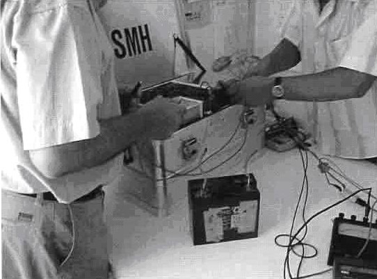
This technical note aims at describing a test I personally conducted in Izmir, Turkey on July 17, 2005. The purpose of the experiment was to check the energy balance with respect to input and output of an apparatus, which was the embodiment of the invention described in international patent WO 2004/091083 A1.
The apparatus was confined inside a metallic box, and I was allowed to inspect everything outside this box. However, in order to protect the core ideas of the invention, I was not supposed to check all the details of the internal parts. According to the inventor the apparatus is predominantly a mechanical system, without any kind of energy storage inside the box like batteries, accumulators, flywheels, combustion motors, chemical or radioactive reactions. I believe the intentions of the inventor were in good faith.
The experimental setup was quite simple, as shown schematically in Figure 1. It consisted of placing the box with unknown contents, from which DC voltages and currents were expected to be generated, on a table in the middle of a room. From the box, a cable with two terminal contacts was available for connecting electrical loads. I placed measurement instruments between the box output terminals and the load. The load consisted of an ordinary AC-DC inverter, this inverter being connected to an incandescent lamp. The working principle of the inverter and the lamp type were not relevant for analyzing the results, because the output power delivered by the box was measured immediately after the output terminals. Photographs of the setup are included in Appendix A.
Figure 1: Experimental Setup

After a short start procedure, the metallic box together with the lead were fully isolated from the environment (in what concerns other physical contacts like cable connections to the public mains) during the whole duration of the measurements. This situation is in agreement with the description given in the international patent [ WO 2004/091-83 ] mentioned above. Since the energy input entering the apparatus was quite modest, as it will become clear further in this note, the main issue was then to measure the delivered energy output.
I had prepared the power measurements with care, by using reliable instruments I personally brought with me from my own university laboratory. In order to measure the DC voltage directly out of the positive and the negative electrical terminals I used two different voltmeters in parallel, one analog (constructed with permanent magnets and wires) and another digital (that employs electronic circuits to acquire and to display the measured values). These instruments are based on completely different working principles. Also for measuring the DC current coming out the positive terminal and entering back into the negative terminal, I placed two ammeters in series, again one analog and the other digital. If electromagnetic waves would interfere with the measurements, they would disturb one or the other instrument, but not all four pieces at the same time in the same way.
Before starting the experiment, no kind of audible noise was being produced by the apparatus. Also, I measured the voltage differences between the internal and external connection points, and no potential differences between the internal and external connection points, and no potentials were found. So far as I could observe, the apparatus was completely at rest.
The start procedure consisted of connecting a small 12V DC lead-acid accumulator to two contact points inside the box, during a short time interval (see Figure B1 in Appendix B). I observed this time interval with the help of my own watch, and it was more than 5 seconds, but less than 10 seconds. In later calculations it is reasonable to consider this start time interval as being equal to 8 seconds. After that, no other energy input was connected to the box by means of cables.
Immediately after the start procedure I could hear noise as produced by rotating parts inside the box. The inventor communicated that a stabilizing time interval of about 10 minutes should be respected before switching on the load (inverter plus lamp). During this interval it was possible to observe in both voltmeters that DC voltage was being generated on the terminals, which decayed slowly from 12.9 V DC to 12.5 V DC. The displayed values in the analog and digital instruments were in good match. After 10 minutes I switched on the DC inverter.
In the following hours I observed and registered by hand the values of voltages and currents displayed by the instruments. The displayed values were quite stable; therefore I decided to register them first after 15 minutes, later at each half hour.
From time to time I sensed the internal parts in the box with my hands, looking for temperature gradients, but I could not perceive any noticeable temperature rise with respect to the ambient. After 5 hours I took the decision to stop the measurements.
Results are given in Table 1. The displayed values of both voltmeters and both ammeters were in good agreement (in view of the precision of the instruments), as it can be seen in Table 1. For this reason, I dare to conclude that the results I’ve registered are reliable, to the best of my knowledge.
From Table 1 it is possible to see that the generated output voltage and current remained fairly constant during the 5 hours test.
Table 1

Remarks:
So far the experiment has been described. The following comments are my own subjective interpretation.
Power calculations based on the registered values of voltages and currents in Table 1 lead to the conclusion that much more energy is delivered by the box, which was completely isolated from the environment, than the possible initial energy input used to start the process. For instance, the energy output after 5 hours is approximately given by
( 12.25 V ) x ( 2.3 A ) x ( 5 x 60 x 60 s ) = 507 kJ
Therefore, in order to input this same amount of energy into the box during the start procedure, the current that would have been drawn from the small 12 V lead-acid accumulator for the duration of 8 seconds is found to be
507 kJ / ( 12 V ) x ( 8 s ) = 5280 A
which is physically not possible to realize considering the volume of the accumulator and the simple connector contacts shown in Appendix B!
Considering the inventor’s assurance that the apparatus is mainly a mechanical device, and that no kind of energy storage was implemented inside the box, it isn’t clear where the measured excess of energy out of the box is coming from --- whether out of electromagnetic fields or as the result of some anomaly associated with rotating bodies in terms of inertia. This is a most interesting phenomenon, which deserves further attention.
After analyzing the results in detail, together with the drawing and explanations provided by the inventor (see Appendix C), it was possible to recognize from the schematics certain mechanical structures, the so-called homopolar machines, turning at high speed of rotation.
This is a really exciting idea because a link could be established between the apparatus under observation and a famous experiment performed in 1831 by Michael Faraday, the inventor of the electrical machines. In the academic literature this old experiment is known as the Paradox of Faraday’s Disk.
Indeed, many other scientists hypothesize about the possibility of constructing homopolar machines with efficiency above 100% (see, for instance, the paper of Brice DePalma, "On the Possibility of Extraction of Electrical Energy Directly from Space" in the academic journal Speculations in Science and Technology, Sept. 1990, Vol. 13, No. 4…) [ see also: http://www.rexresearch.com/depalma/depalma.htm ]. However, up to the present time nobody has demonstrated in a convincing way a practical application of the principle. Perhaps the inventor has discovered the missing link in these machine; who knows?…
Of course, the straightforward way to check this possibility would be to inspect the contents inside the box. However, the inventor is only willing to allow that after a solid commitment with a research institution or an industrial partner.
So, the next step would be to exclude the possibility of some kind of conventional electrochemical energy processing inside the apparatus. For this purpose the realization of another experiment, similar to the one described above, would be advisable, but not without long run-time of measurements. The results should convince that, indeed, it is not possible to get the same energy output with the best commercially available battery. Therefore, a new experiment may take many days (about 4 or 5) to be executed.
Eindhoven
28 July 2005

Appendix 1
Experimental Setup
Figure A1 ---

Global view of the experimental setup, illustrating the apparatus under test inside a metallic box. In the front plane are the measurement instruments. The load is a combination of an inverter (with circular shape), connected to the box output terminals, and an incandescent lamp. Four voltmeters (multimeters) placed on the box cover, were connected by the inventor for monitoring purposes.
Figure A2 ---

Contents inside the metallic box and different views of the setup.
Figure A3 ---

Details of the DC-AC inverter used as a load.
Figure A4 ---

Another view of the embodiment of the invention. The metallic box has the external dimensions: 55 cm x 38 cm x 27 cm. The components inside the box, excluding wire and isolation materials, weigh 20 kg. (Information provided by the inventor).
Appendix B
Startup
Figure B1 ---
Preparing the startup process.
Figure B2 ---

Details of the accumulator used for startup.
http://www.ocean-star.org


Links:
http://www.youtube.com/watch?v=ybn--DsyzBk --- Video
http://www.ocean-star.org/german/presse2.html
http://www.ocean- star.org/center.html
http://www.haber7.com/haber.php?haber_id=71457
http://www.milligazete.com.tr/index.php?action=show&type=news&id=6643
http://www.haberarsivi.com/haber.asp?id=6863
http://www.inndir.com/haberler.php?id=36997
http://www.zaman.com.tr/webapp-tr/haber.do?haberno=130993
http://www.forumca.net/showthread.php?t=63173
DEVICE HAVING AN ARRANGEMENT OF MAGNETS
Inventor(s): YILDIZ MUAMMER [TR] + (YILDIZ, MUAMMER)
Also published as: DE102007037186 // EP2153515
Cited documents: EP0088909 // DE202005020288U // EP0501427 // DE2847618 // EP1489734
Abstract -- The invention relates to a device having an arrangement of magnets for generating an alternating magnetic field that interacts with a stationary magnetic field. The device comprises a rotor (1) and a stator (2) disposed coaxially to a rotatably mounted shaft (5). The rotor (1) comprises one or more first magnet sequences and the stator (2) one or more second magnet sequences. The first and second magnet sequences each comprise two or more dipole magnets, the arrangement and orientation of which may vary.
Apparatus with an arrangement of magnets
The invention relates to an apparatus to the generation of a magnetic alternating field, which interacts with a stationary magnetic field.
The interaction of a stationary magnetic field and a magnetic alternating field becomes already utilized since longer, for example within the range of brushless DC motor and magnetic levitation transport systems.
The invention is the basis the object, an improved apparatus to the generation of a magnetic alternating field, which interacts with a stationary magnetic field to create.
This object becomes by apparatus with rotor and stator dissolved, which coaxial to rotatable stored shaft arranged are, whereby rotor one or more first magnet sequences and stator one or more second magnet sequences exhibits, whereby one or more first magnet sequences in each case two or more on outer surface coaxial to shaft oriented first circular cylinder arranged dipole magnets cover, whose dipole axles with a tangent include to the scope of the outer surface by a point, at which the dipole axles break through in each case the outer surface, in each case an inclination angle, which lies in a range of 14 degree to 90 degree, and which one or more second magnet sequences in each case two or more on one Outer surface coaxial to shaft oriented second circular cylinder arranged dipole magnets cover, whose dipole axles with a tangent include to the scope of the outer surface by a point, at which the dipole axles break through in each case the outer surface, in each case an inclination angle, which lies in a range of 14 degree to 90 degree, whereby exhibits the one or more in each case first magnet sequences and the one or more second magnet sequences regarding a vertical plane a pitch angle arranged to a shaft axis of the shaft, which lies in a range of 10 degree to 80 degree or of 280 degree to 350 degree, and whereby includes the one or more first magnet sequences and the one or more second magnet sequences an angle of attack, that in a range of 0 degree to 90 degree lies.
The formulations “their dipole axles with a tangent to the scope of the outer surface by a point, specified above, at which the dipole axles break through the outer surface, in each case an inclination angle in each case include, in a range of 14 the degree to 90 degree lie” are to be understood in such a way that each of the dipole magnets of the rotor and the stator can exhibit an individual inclination angle. The single limitation of the respective individual inclination angle is that it lies in a range of 14 degree to 90 degree. This covers the case that two exhibit or more dipole magnets the same inclination angle. So e.g. is it. also possible that all dipole magnets of the rotor and/or the stator exhibit the same inclination angle.
The formulation specified above “whereby the one or the more first magnet sequences and the one or more second magnet sequences regarding a vertical plane in each case a pitch angle arranged to a shaft axis of the shaft exhibit to understand in a range of 10 the degree to 80 degree or of 280 degree to 350 degree lie” is in such a way that each magnet sequence of the rotor and the stator can exhibit an individual pitch angle. The single limitation of the respective individual pitch angle is that it lies in a range of 10 degree to 80 degree or of 280 degree to 350 degree. This covers the case that two or more magnet sequences exhibit the same pitch angle. So e.g. is it. also possible that all magnet sequences of the rotor and/or the stator exhibit the same pitch angle.
In the case that two magnet sequences on the rotor and/or the stator exhibit different pitch angles, it is also these magnet sequences the associated angle of attack different. Beyond that specified the above solve the problem by an apparatus with a coaxial inner stator, a coaxial rotor arranged to the shaft and a coaxial outside stator arranged to the shaft, arranged to a rotatable stored shaft, whereby the rotor is connected regarding the inner stator at least partial radial other outer arranged and solid with the shaft and the outside stator is at least partial radial other outer arranged regarding the rotor, whereby the inner stator two or more exhibits arranged dipole magnets, which are uniform distributed over the circular cylinder extent and are regarding a shaft axis of the shaft axial against each other so offset on an outer surface of a circular cylinder that itself on the outer surface of the circular cylinder a treppenförmige arrangement that Dipole magnets results in and adjacent dipole magnets regarding the shaft axis axial partly overlap, whereby the rotor two or more exhibits longitudinal series with in each case four or more uniform dipole magnets distributed on the circular cylinder extent on an outer surface of a circular cylinder, whereby the dipole magnets of series are appropriate for against each other alternate so offset in a vertical plane longitudinal to the shaft axis and are the dipole magnets of adjacent rows that they form axial to the shaft axis a zigzag pattern uniform over the circular cylinder extent, and whereby the outside stator two or more exhibits arranged dipole magnets on an outer surface of a circular cylinder, which is uniform on the outer surface distributed.
By the particular arrangement of the dipole magnets of the rotor and the stator and/or. the stators cause formed magnetic fields that the rotor becomes free floating held. The apparatuses according to invention works in such a way as a magnetic bearing. Surprisingly shown has itself that by the particular arrangement of the dipole magnets of the rotor and the stator and/or. the stators with rotation of the rotor a magnetic alternating field generated becomes, a to a large extent lossless rotation of the rotor relative the stator and/or. the stators allowed. This can become for a multiplicity of technical applications utilized, for example for a particularly friction-poor storage itself of a preferably rapid rotary shaft. In the ensuing description mathematical, in particular geometric terms become, e.g. parallel, vertical, plane, cylinder, angle, etc. used, which can be registered in technical designs, but in the practice due to the production-determined tolerances never perfect satisfied to become to be able. For the person skilled in the art it is clearer therefore that this description is to be regarded only as description of ideal. The description includes however tacitly also similar devices with general conventional tolerances also.
The shaft runs in an axis, the so-called. Shaft axis, and is more rotatable around this axis. The shaft preferably is as straight circular cylinders formed, whereby those forms axis of rotation of the circular cylinder the shaft axis.
It is possible that within the first and/or second magnet sequences adjacent dipole magnets exhibit the same polarity. It is also possible that within the first and/or second magnet sequences adjacent dipole magnets exhibit a different polarity.
In a prefered embodiment the polarity of the two is or more dipole magnets within or several magnet sequences a same. Regarding the shaft axis that means that the north poles of all dipole magnets point within or several magnet sequences either to the shaft axis or of it remote are. Meant or several magnet sequences are magnet sequences in or more of the first magnet sequences and/or magnet sequences in or more of the second magnet sequences. It is also possible that the polarity of all dipole magnets of the rotor and/or. the stator same is, is called that the north poles of all dipole magnets of the rotor and/or. the stator either to the shaft axis show or of it remote are. Bottom polarity of a dipole magnet the orientation magnetic Nordund of south pole of the dipole magnet becomes understood.
In another prefered embodiment is the polarity of the two or more Dipole magnets of a magnet sequence alternate. It is possible that within a magnet sequence adjacent dipole magnets exhibit a different polarity. In this case successive dipole magnets of a magnet sequence show for example the sequence… SNSN… (N = north pole; S = south pole). It is also possible that the change of the polarity is irregular, so that itself for example the sequence… NNSNNS… results in.
Preferably the dipole axles of the dipole magnets parallel plane arranged vertical to that to the shaft axis run.
Preferably the distance of adjacent dipole magnets of the two is or more dipole magnets within or several magnet sequences a constant. Meant or several magnet sequences are magnet sequences in or more of the first magnet sequences and/or magnet sequences in or more of the second magnet sequences.
It is possible that the distance of adjacent dipole magnets is within the one or more first magnet sequences of the rotor and/or the stator constant. In this case it is possible that the distance of adjacent dipole magnets of the two differs or more dipole magnets within the one or more first magnet sequences dipole magnets of the two adjacent of the distance or more dipole magnets within the one or more second magnet sequences. It is also possible that the distance of adjacent dipole magnets of the two agrees or more dipole magnets within the one or more first magnet sequences dipole magnets of the two adjacent with the distance or more dipole magnets within the one or more second magnet sequences.
It is also possible that the inclination angle of the dipole axles within the one or more first magnet sequences and/or the one or more is second magnet sequences constant. Preferably these constant inclination angles in a range of 14 degree to 90 degree lies.The pitch angle of a magnet sequence indicates the intersection angle between a tangent, the one curve touched, and a vertical plane longitudinal formed by the two or more dipole magnets within the magnet sequence to the shaft axis. Generally case can change the pitch angle of a magnet sequence in the course of the magnet sequence. In a prefered embodiment the pitch angle of a magnet sequence is constant, comparable with the slope of a thread. In the case of a constant pitch angle the two lie or more dipole magnets of the magnet sequence with a development on a straight one.
It is prefered, if exhibits the one or more first magnet sequences the same pitch angle, first pitch angle mentioned. Further it is prefered, if exhibits the one or more second magnet sequences the same pitch angle, second pitch angle mentioned.
The angle of attack between a first magnet sequence and a second magnet sequence indicates the intersection angle between a first tangent, the one curve touched, and a second tangent, the one curve touched formed formed by the two or more dipole magnets within the first magnet sequence by the two or more dipole magnets within the second magnet sequence for a development of the first and second magnet sequences. Generally case can change the angle of attack in the course of the magnet sequences.
In a prefered embodiment the angle of attack between a first magnet sequence and a second magnet sequence is constant. In this case is the respective pitch angles of the first magnet sequence and the second magnet sequence constant.
In a particularly prefered embodiment a single, constant angle of attack exists for all first and second magnet sequences. In this case the one or more exhibits first magnet sequences the same first pitch angle and the one or more second magnet sequences exhibits the same second pitch angle.
In a prefered embodiment two or more begin first magnet sequences at a first vertical plane arranged to the shaft axis and end at a second vertical plane arranged to the shaft axis. In same wise is it possible that two or more begin second magnet sequences at a first vertical plane arranged to the shaft axis and at a second vertical plane arranged to the shaft axis end. It is possible that all magnet sequences of the rotor and/or the stator at a first front surface of the rotor oriented transverse to the shaft axis and/or. the stator begin and at a second front surface of the rotor oriented transverse to the shaft axis and/or. the stator end. Preferably the one or more is first magnet sequences and/or the one or more second magnet sequences so arranged that groups of two or more magnet sequences are formed. A group of two or more magnet sequences is characterised by the fact that the distance of the magnet sequences is to each other smaller than the distance to magnet sequences, which do not belong to the group.
In a prefered embodiment an air gap between the rotor and the stator exhibits a gap width of 0.1 mm up to 50 mm. Particularly prefered is it, if the gap width exhibits a value from 1 mm to 5 mm.
In a prefered embodiment the rotor and the stator in that point vertical plane one arranged to the shaft axis circular cross section essentially exhibit. With the term “essentially circular” is stated that the cross section due to the production-determined tolerances the geometric perfect circular shape does not come satisfied, it however close.
Preferably the outer surface of the first circular cylinder the outer periphery of the rotor is umbeschrieben and/or the inner periphery of the rotor in-described. First that the outer surface of the first circular cylinder the outer periphery of the rotor it umbeschrieben is refers to the case that the rotor is at least partial radial other inside arranged regarding the stator. The latter that the outer surface of the first circular cylinder the inner periphery of the rotor is in-described, refers to the case that the rotor is at least partial radial other outer arranged regarding the stator.
Preferably the outer surface of the second circular cylinder the outer periphery of the stator is umbeschrieben or the inner periphery of the stator in-described. First that the outer surface of the second circular cylinder the outer periphery of the stator it umbeschrieben is refers to the case that the rotor is at least partial radial other outer arranged regarding the stator. The latter that the outer surface of the second circular cylinder the inner periphery of the stator is in-described, refers to the case that the rotor is at least partial radial other inside arranged regarding the stator. In a prefered embodiment are the dipole magnets of the rotor and/or. the stator so in each case on the outer surface of the first circular cylinder and/or. the second circular cylinder arranged that the outer surface of the first circular cylinder and/or. the second circular cylinder the dipole magnets of the rotor and/or. the stator not in each case touched. With the term “non-cutting touched” is stated that the respective outer surface does not cut the dipole magnets touched, but their volume. It means that the respective outer surface concerns the dipole magnets exclusive, i.e. superficial touched.
It is particularly favourable, if the rotor and/or the stator cover a support body from non magnetic material with recesses to the receptacle of the dipole magnets. The support body serves to hold the dipole magnets at a defined position. The dipole magnets are in recesses of the support body intended in addition fixed.
In a prefered embodiment the stator is formed as inner stator, which is rotor regarding the stator formed as inner stator at least partial radial other outer arranged and solid with the shaft connected, and the apparatus exhibits a coaxial outside stator arranged to the shaft, which is at least partial radial other outer arranged regarding the rotor. In addition the dipole magnets in or more second magnet sequences of the uniform over the scope of the second circular cylinder distributed and regarding the shaft axis axial against each other so offset are with this prefered embodiment that on the outer surface of the second circular cylinder a treppenförmige arrangement of the dipole magnets results and partly overlaps adjacent dipole magnets regarding the shaft axis axial. Besides the rotor k exhibits first magnet sequences with this prefered embodiment, whereby k is a whole number of large or same four, and which is two or more dipole magnets of the k first magnet sequences so formed that her two or more on that Outer surface of the first circular cylinder longitudinal series with in each case k uniform dipole magnet distributed on the scope of the first circular cylinder train. Beyond that the dipole magnets of series lie in a vertical plane longitudinal to the shaft axis with this prefered embodiment, and the dipole magnets of adjacent rows are against each other alternate so offset that they form axial to the shaft axis a zigzag pattern uniform over the circular cylinder extent. In addition the outside stator two or more exhibits arranged dipole magnets with this prefered embodiment, which are uniform distributed on the outer surface on one the outer surface of a third circular cylinder.
In a prefered embodiment the magnets of the inner stator, the rotor and the outside stator at least partly overlap. A partial coverage of two magnets is satisfied if a vertical plane longitudinal to the shaft exists, which runs by each of the two magnets. From a complete coverage of two magnets spoken becomes if for each point one of the two magnets a vertical plane longitudinal to the shaft exists, which runs by each of the two magnets. A partial coverage of three magnets is satisfied if a vertical plane longitudinal to the shaft exists, which runs by each of the three magnets. From a complete coverage of three magnets spoken becomes if for each point of two of the three magnets a vertical plane longitudinal to the shaft exists, which runs by each of the three magnets. It can become an engagement factor defined: with an engagement factor of 0% two/three magnets do not overlap, with an engagement factor of 100% overlap two/three magnets complete.
In a particularly prefered embodiment of the apparatus are the inner stator and the rotor axial arranged fixed to the shaft axis and the magnets of the inner stator and the rotor overlap complete. Beyond that the outside stator is axial arranged movable to the shaft axis, so that that Engagement factor of the magnets of the outside stator and the magnets of the rotor continuous in a range from 0% to 100% changed will can.
The magnets of the inner stator, the rotor and the outside stator define one meant hollow cylinder each with common longitudinal axis (= the shaft axis), are arranged within whose wall the magnets. In case of a partial coverage of the three magnets the three meant hollow cylinders lie on top of each other at least in a portion the longitudinal axis radial. This portion the longitudinal axis forms thereby the longitudinal axis of the meant cylinder cavity, whose longitudinal axis coaxial runs to the shaft. In case of a complete coverage of the magnets of the three devices (= inner stator, rotor and outside stator) two of the three meant hollow cylinders always radial lie over or bottom third of the three meant hollow cylinders.
Preferably the rotor has the form of a drum or a cup, i.e. it points an hollow cylinder with annular cross section and/or. a pipe section up, whose is a face by a coaxial circular disk covered. In the center of the circular disk the rotor exhibits a bore, by whom the shaft axis runs. The circular disk knows an additional ring inertial, which serves for the compound of the rotor with the shaft, e.g. by means of a screw connection, which runs by a radial bore in the ring. The rotor is stationary connected with the shaft, is called the relative position of the rotor regarding the shaft remains with a rotation of the shaft during the intended operation of the apparatus unchanged. Nevertheless the bolt mounting, which connects the rotor with the shaft, can become dissolved, e.g. to the maintenance, purification, exchange of defective parts, etc. The hollow cylinder of the rotor surrounds the outer surface of the cylindrical inner stator bottom formation of an annular air gap between the rotor and the inner stator.
It is also possible that the circular disk, which takes a face off of the rotor hollow cylinder exhibits two or more dipole magnets, which are arranged on a circumference regarding the center of the circular disk. The magnetic dipole axle of the dipole magnets runs parallel to the shaft axis. A bottom magnetic dipole axle, or short: Dipole axle, a dipole magnet becomes a straight one understood, which connects the south pole and the north pole of the dipole magnet. Preferably the dipole magnets are uniform distributed on the circumference.
It is particularly favourable, if the outside stator surrounds hollow-cylindrical or the circle-tubular rotor. It is possible for the example that the outside stator the form of an hollow cylinder and/or. Circular pipe exhibits, whose central axis with the central axis of the rotor coincides. The hollow cylinder of the outside stator surrounds the outer surface of the hollow-cylindrical rotor bottom formation of an annular air gap between the outside stator and the rotor.
With a prefered embodiment the dipole magnets of the outside stator exhibit a rod-shaped geometry and run with their Stabbzw. Longitudinal axis parallel to longitudinal axis of the circular pipe, i.e. parallel to the axis of the shaft (= shaft axis). It is prefered, if the dipole magnets of the outside stator essentially extend over the whole length of the outside stator formed in form of a circular pipe. “Essentially” it can mean that the outside stator at its faces exhibits still another edge or a cover disk, at which the dipole magnets ends. The magnetic dipole axles of the dipole magnets of the outside stator preferably lie in a plane, which runs rectangular to the longitudinal axis of the dipole magnets.
It is also possible that the preferably rod-shaped dipole magnets of the outside stator are arranged in the form of or more rings along the scope of the outside stator. Everyone of the rings formed from the dipole magnets lies in a plane, which runs vertical to the shaft axis. A ring the formed dipole magnets are among themselves by bars from non magnetic material from each other separate. Between the single rings formed from the dipole magnets annular ridges from non magnetic material run along the scope of the outside stator. Preferably the insides of the dipole magnets oriented to the shaft axis lie on an outer surface of a circular hollow cylinder. It is prefered that the dipole magnet rings are uniform over the full height of the outside stator distributed.
In a prefered embodiment of the invention the inner stator and the outside stator are fixed arranged. The inner stator and the outside stator can be assistance of fasteners and/or guide means not-rotatable at a mechanical housing to the receptacle of the apparatus arranged.
In a prefered embodiment the shaft penetrates the inner stator not, but is only with the rotor connected. The rotor becomes held by the magnetic fields of the apparatus in Schwebe. Therefore an additional mechanical storage of the rotor is not necessary by means of a bearing. The shaft becomes formed in this case by a pin, which is distant outward from the circular disk at the face of the rotor arranged at the rotor. In an alternative embodiment of the apparatus extended itself the shaft over the whole length of the apparatus. The shaft runs along the central axis of the inner stator and serves as additional mechanical guide member of the rotor. In this case the inner stator points preferably a bearing, e.g. a rolling bearing, up, is rotatably supported in which the shaft.
It is also possible that the rotor and the outside stator consist in each case of two halves. Preferably these halves are symmetrical in each case formed, concerning a plane of symmetry, which runs vertical to the shaft axis. This plane of symmetry penetrates simultaneous also the inner stator, which is split up in this way into two same prolonged meant halves. In the range that
Plane of symmetry is a fastener arranged, is stationary fixed by means of which the inner stator at the mechanical housing. Preferably this fastener separates the two halves of the rotor and the two halves of the outside stator bottom formation from air gaps. It is also possible that the two halves of the outside stator are more slidable concerning the shaft axis.
In a prefered embodiment the two halves of the outside stator symmetrical are so more slidable to the plane of symmetry that the engagement factor of the magnets of the rotor is more adjustable by the magnets of the outside stator stepless in a range of zero percent to one hundred percent. That e.g. is. realizable by means of a threaded shaft with two threads moving in opposite directions, moving in opposite directions arranged at which the two halves of the outside stator are in the threaded portions. Depending upon a direction of rotation of the threaded shaft the two halves of the outside stator move away one on the other too or from each other.
An angle [alpha] is defined as the angles between the dipole axle of a dipole magnet of the inner stator and a tangent to the scope of the inner stator, whereby the tangent runs by a point on the scope, in which the dipole axle the scope penetrates. An angle ss is defined as the angles between the dipole axle of a dipole magnet of the rotor and a tangent to the scope of the rotor, whereby the tangent runs by a point on the scope, in which the dipole axle the scope penetrates. An angle Y is defined as the angles between the dipole axle of a dipole magnet of the outside stator and a tangent to the scope of the outside stator, whereby the tangent runs by a point on the scope, in which the dipole axle the scope penetrates. In a prefered embodiment of the invention the angles [alpha] are appropriate, ss and for y in a range of values of 14 [deg.] < [alpha], ss, y <= 90 [deg.]. It is possible that the dipole axle of a dipole magnet in a plane vertical runs to the shaft axis, which an angle [alpha], ss, Y of 90 [deg.] corresponds.
In the case that mentioned tangent runs to the scope of the inner stator parallel to the tangent to the scope of the outer surface of the second circular cylinder, the angle [alpha] corresponds to the inclination angle. In the case that mentioned tangent runs to the scope of the rotor parallel to the tangent to the scope of the outer surface of the first circular cylinder, the angle corresponds ss to the inclination angle.
It is particularly favourable, if the dipole magnets of the inner stator and/or the outside stator in a cutting plane vertical exhibit a rectangular or a trapezoidal cross section to the shaft axis. Further it is particularly favourable, if the dipole magnets of the rotor in a cutting plane vertical exhibit a point-symmetrical, preferably a circular, to the magnetic dipole axle of the dipole magnets cross section. In addition, there is other one, non-point-symmetrical cross sections possible, e.g. trapezoidal, triangular, or irregular formed cross sections.
In an other prefered embodiment the dipole magnets of the inner stator and/or the outside stator parallel exhibit the largest expansion to the shaft axis. It means that the dipole magnets of the inner stator and/or the outside stator a geometry exhibit rod-shaped. The expansion parallel to the dipole axle is small parallel as the expansion to the shaft axis. It is possible that all dipole magnets of the inner stator a same outer shape, i.e. the same geometry, exhibit. It is also possible that all dipole magnets of the outside stator a same outer shape, i.e. the same geometry, exhibit. It is also possible that all dipole magnets of the rotor a same outer shape, i.e. the same geometry, exhibit. With outer shape and/or. Geometry are only the outer dimensions meant; the magnetic orientation, i.e. the layer of the magnetic north pole and the magnetic south pole, is independent of it and can individual from magnet to magnet vary.
In a prefered magnet assembly of the apparatus the magnets of the inner stator, the rotor and the outside stator are same in each case oriented, so that they repel themselves in each Winkellage of the rotor. For the example that points north pole outward, with all dipole magnets on the rotor that north pole inward and that south pole outward, and with all dipole magnets on the outside stator that south pole inward with all dipole magnets on the inner stator.
Other features, details and advantages of the invention result from the ensuing description of several embodiments of apparatuses according to invention on the basis the designs.
Fig. 1a, 1 b are cross sections of a stator with a magnet sequence;

Fig. 2a, 2b are cross sections of stators with multiple magnet sequences;

Fig. 3a, 3b developments of outer surfaces of stators;

Fig. 4 developments of outer surfaces of a stator and a rotor;

Fig. 5a - 5c a side view and cross sections of a stator;
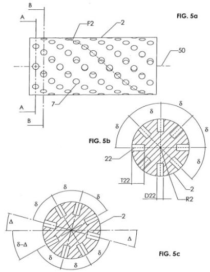
Fig. 6a - 6f shows, a longitudinal section and cross sections of a rotor; Fig. 7a - 7d views and a cross section of a stator;


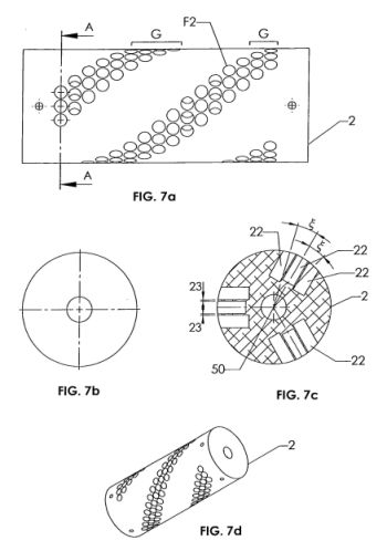
Fig. 8a - 8d shows and a cross section of a stator;

Fig. 9a - 9h illustrate the pitch angle;

Fig. 10 illustrates of the relationship between Magnet sequences and magnet rows of the rotor;


Fig. 12a an oblique view of the inner stator of the apparatus after Fig. 11 without magnets (= stator core);

Fig. 12b a schematic representation of the inner stator of the apparatus after Fig. 11, vertical to the shaft axis;
Fig. 13 a development of the magnet assembly on the inner stator of the apparatus after Fig. 11 ;

Fig. 14 a section by the inner stator of the apparatus after Fig. 11, along in Fig. 12b indicated line A-A;

Fig. 15a a view of the fastener of the apparatus after Fig. 11, vertical to the shaft axis;

Fig. 15b a view of the fastener of the apparatus after Fig. 11, toward the shaft axis;
Fig. 16 an oblique view of the rotor of the apparatus after Fig. 11;

Fig. 17a a schematic view of the inner stator and the rotor of the apparatus after Fig. 11; Fig. 17b a scheme of possible inclination angles of the dipole magnets of the rotor of the apparatus after Fig. 11 ;

Fig. 18a a development of the magnet assembly of the rotor of the apparatus after Fig. 11, along in Fig. 16 direction indicated XY;

Fig. 18b a detail view of the development in accordance with Fig. 18a;

Fig. 19a a longitudinal section by a mechanical housing to the receptacle of the apparatus after Fig. 11 ;
Fig. 19b a section by the outside stator of the apparatus after Fig. 11, vertical to the shaft axis;

Fig. 20 is an oblique view of the outside stator and the mechanical housing to the receptacle of the apparatus after Fig. 11;

Fig. 21 a scheme of the magnet assembly on the stators and the rotor of the apparatus after Fig. 11, shown as section along that Shaft axis;

Fig. 22 a scheme of the magnet assembly on the stators and the rotor that Apparatus after Fig. 11, shown as section along in Fig. 11 indicated line B-B;

Fig. 23a is a schematic representation of a dipole magnet of the outside stator of the apparatus after Fig. 11 ;

Fig. 23b is a schematic representation of a dipole magnet of the inner stator of the apparatus after Fig. 11 ; and
Fig. 2a shows a cross section of a stator 2 with first and a second magnet sequence. The stator 2 covers two dipole magnets 8, which are next to each other arranged. The magnetic dipole axles 80 of the two dipole magnets 8 are appropriate for parallel in the cutting plane and run. The left dipole magnet 8 is component of the first magnet sequence of the stator 2, the right dipole magnet 8 is component of the second magnet sequence of the stator 2.
Fig. 2b shows a cross section of a stator 2 with first and a second magnet sequence. The stator 2 covers two dipole magnets 8, which are next to each other arranged. The magnetic dipole axles 80 of the two dipole magnets 8 lie in the cutting plane, cut the shaft axis 50 and include an angle [lambda]. The left dipole magnet 8 is component of the first magnet sequence of the stator 2, the right dipole magnet 8 is component of the second magnet sequence of the stator 2.
Fig. 3a shows a development of an outer surface M2 of a cylindrical stator with a magnet sequence F2. The orientation of the outer surface M2 is 50 defined by the indication of the shaft 5 and the shaft axis. The magnet sequence F2 begins at the left side of the outer surface M2 and ends at the right side of the outer surface M2. The dipole magnets 8 of the magnet sequence F2 lie on a straight one. The arrangement of the magnet sequence F2 on the outer surface M2 is the straight one defined by a pitch angle b. The pitch angle b corresponds to the intersection angle between the straight one of the magnet sequence F2 and a vertical plane longitudinal to the shaft axis 50. The magnet sequence F2 describes a whole turn (= 360 degree) in its course along the shaft axis 50 around the shaft axis 50.
Fig. 3b shows - corresponding Fig. 3a - a development of an outer surface M2 of a cylindrical stator with a magnet sequence F2. Compared with in Fig. 3a magnet sequence shown is the pitch angle b in Fig. 3b magnet sequence shown F2 larger. Therefore the magnet sequence F2 in their course describes an half turn (= 180 degree) along the shaft axis 50 only around the shaft axis 50.
Fig. a development of an outer surface M2 of a stator with magnet sequences F2 and a development of an outer surface M1 the stator of an associated rotor with magnet sequences F1 shows 4. The dipole magnets of the magnet sequences F1, F2 lie in each case on straight ones. Those the stator associated straight one and those the rotor associated straight one separate a bottom angle of attack C.
Fig. 5b shows a cross section in Fig. ä represented stator 2 along a cutting plane A-A, like in Fig. ä shown. In the section uniform are to be recognized over the scope of the stator 2 distributed recesses 22 for the dipole magnets. Everyone of the recesses 22 visible in the section is a separate magnet sequence F2 associated. Related to the shaft axis of the stator 2 is the recess 22 of a magnet sequence F2 around the angle [delta] opposite the recess 22 of an adjacent magnet sequence F2 rotated. In the present embodiment the angle [delta] amounts to = 45 degree. The radius R2 of the cylindrical stator 2 amounts to in the present embodiment 45 mm. The depth T22 of the cylindrical recesses 22 amounts to in the present embodiment 22.22 mm, its diameter D22 has e.g. a value of 10 mm.
Fig. 5c shows a cross section in Fig. ä represented stator 2 along a cutting plane B-B, like in Fig. ä shown. Opposite in Fig. 5b represented section are the recesses around an angle [delta] around the shaft axis 50 twisted. Within a magnet sequence F2 adjacent dipole magnets are 8 thus against each other twisted regarding the shaft axis 50 around an angle [delta]. In the present embodiment the angle [delta] amounts to = 12 degree.
Fig. 6a shows a plan view of a rotor 1. The rotor 1 has the form of an hollow cylinder with an height of H. The height of H e.g. amounts to. 235 mm. The wall of the rotor 1 exhibits the wall penetrating holes, which serve 15 as recesses for the receptacle of the dipole magnets. The magnet sequences of the rotor 1 begin in a distance E of the face of the rotor 1 and end in the distance E of the opposite face of the rotor 1. In the present embodiment the distance E amounts to 35 mm. The diameter D15 of the cylindrical recesses 15 e.g. amounts to. 10 mm. Each recess 15 is a retaining mechanism to the fixation of the dipole magnets 7 associated used into the recesses 15. The retaining mechanism consists of a threaded hole 150 and a threaded pin, which are pivoted into the threaded hole and for the fixation of the dipole magnet 7 serve.
Fig. 6b shows a view of on the left of in Fig. 6a of represented rotor 1. The outer diameter D1A of the rotor 1 e.g. amounts to. 143 mm, its inner diameter D1 I e.g. 93 mm. The rotor 1 exhibits uniform threaded holes M6 distributed over the scope, which are in a distance DM6 of the outer periphery mounted at its face. The threaded holes M6 can exhibit for example a metrical ISO thread with a nominal diameter M6 (ISO = international organization for standardization). The distance DM6 e.g. amounts to. 10 mm. These threaded holes M6 serve to fasten a lid on the face of the rotor 1 is 5 connected over which the rotor 1 with the shaft. At each face the rotor 1 e.g. exhibits a circumferential groove 16, their outer diameter D16. 97 mm amounts to. This groove 16 takes up a corresponding circular projection of the lid.
Fig. 6c shows a three-dimensional view in Fig. 6a of represented rotor 1.
Fig. 6d shows a longitudinal section in Fig. 6a of represented rotor 1 along in Fig. 6a indicated cutting plane A-A. The depth TM6 of the Boreholes M6 mounted in the faces points a value from e.g. 20 mm up. The depth T16, of the circumferential grooves 16 arranged at the faces e.g. amounts to. 2 mm, its width B16 has a value of e.g. 2 mm. In Fig. 6d are to be recognized in various recesses of 15 threaded holes 150, which flow into the recesses 15. Adjacent recesses 15 of a magnet sequence e.g. exhibit 50 toward the shaft axis a distance DF1. 11 mm amounts to.
Fig. 6e shows a cross section in Fig. 6a of represented rotor 1 along in Fig. 6d indicated cutting plane B-B. In the section uniform recesses 15 for the dipole magnets, distributed over the scope of the rotor 1, are to be recognized. Everyone of the recesses 15 visible in the section is a separate magnet sequence F1 associated. Related to the shaft axis 50 of the rotor 1 the recess 15 of a magnet sequence F1 is around the angle [delta] 1 opposite the recess 15 of an adjacent magnet sequence F1 rotated. In the present embodiment the angle [delta] amounts to = 20 degree. A dipole axle of a first recess 15 and a central longitudinal axis of a threaded hole 150, which flows to the first recess 15 adjacent recess 15 into one, include an angle [delta] 2, which amounts to in the present embodiment 25 degree.
Fig. 6f shows a cross section in Fig. 6a of represented rotor 1 along in Fig. 6d indicated cutting plane CC. Opposite in Fig. 6e represented section are the recesses 15 around an angle [delta] 1 around the shaft axis 50 twisted. Within a magnet sequence F1 adjacent dipole magnets are 8 thus regarding the shaft axis 50 around an angle [delta] 1 against each other twisted. In the present embodiment the angle [delta] amounts to 1 = 12 degree. Fig. 7a shows a plan view of a stator 2 with group-like arranged magnet sequences F2. Three magnet sequences F2 form in each case a group G.
Fig. 7b shows a view of on the left of in Fig. 7a of stator shown 2.
Fig. 7c shows a cross section in Fig. 7a of stator shown 2 along in Fig. 7a indicated cutting plane A-A. The recesses 22 to the receptacle of the cylindrical dipole magnets 8 are so formed that longitudinal central axis of the recesses 22, which are a group G the formed magnet sequences F2 associated and are in a vertical cutting plane arranged longitudinal to the shaft axis 50, are parallel to the cutting plane run and to each other parallel. The straight ones, which the shaft axis 50 cut and by the points run, in which, longitudinal in the cutting plane, longitudinal central axis of the recesses 22 break through the scope of the stator 2 a circumscribed cylinder, include with adjacent recesses of a group from magnet sequences an angle [xi]. In the present embodiment the angle [xi] has a value of 14.24 degree. The outer edges immediate adjacent recesses 22 e.g. exhibit a minimum distance 23. 1 mm amounted to can.
Fig. 7d shows a three-dimensional view in Fig. 7a of represented stator 2.
Fig. 8a shows a plan view of a stator 2 with group-like arranged magnet sequences F2. Three magnet sequences F2 form in each case a group G. Compared with in Fig. 7a shown stator 2 point with in Fig. 8a stator shown 2 a group G the formed magnet sequences F2 a larger distance from each other up.
Fig. 8b shows a view of on the left of in Fig. 8a of stator shown 2.
Fig. 8c shows a cross section in Fig. 8a of stator shown 2 along in Fig. 8a indicated cutting plane A-A. The recesses 22 to the receptacle of the cylindrical dipole magnets 8 are so formed that longitudinal central axis of the recesses 22, which are a group G the formed magnet sequences F2 associated and are in a vertical cutting plane arranged longitudinal to the shaft axis 50, include parallel to the cutting plane run and with one another an angle [phi] 1. In the present embodiment the angle [phi] has 1 a value of 28 degree. Immediate neighbors within the recesses 22, which are the same group G associated, are 22 from each other separate by a bar of the support body of the stator. The bar exhibits a width J on the scope of the stator 2, as in Fig. 8c outlines. In the present embodiment the width J has a value of 11, 94 mm.
Longitudinal central axis of the recesses 22, which are various groups G associated, 2 includes an angle [phi] at least with one another. In the present embodiment the angle [phi] has 2 a value of 64 degree.
Fig. 8d shows a three-dimensional view in Fig. 8a of represented stator 2.
Fig. 9a to 9h show in each case a development of the outer surface M1, M2 of a rotor 1 and/or. Stator 2. A magnet sequence is symbolized by an arrow. By the arrow direction a direction of a magnet sequence becomes defined. A direction of a magnet sequence is of importance, if the dipole magnets of the magnet sequence exhibit a characteristic polarity succession, which is direction-controlled. For the example it can be for the present invention of importance whether a magnet sequence with three dipole magnets exhibits the polarity SNN or the polarity NNS. The orientation of the outer surface M1, M2 is 50 defined by the indication of the shaft axis.
Fig. 9a shows a pitch angle of b = 10 degree of a magnet sequence, which begins at the left side of the outer surface. Fig. 9b shows a pitch angle of b = 80 degree of a magnet sequence, which begins at the left side of the outer surface. Fig. 9c shows a pitch angle of b = 280 degree of a magnet sequence, which begins at the right side of the outer surface. Fig. 9d shows a pitch angle of b = 350 degree of a magnet sequence, which begins at the right side of the outer surface. Fig. 9e shows a pitch angle of b = 10 degree of a magnet sequence, which begins at the left side of the outer surface. Fig. 9f shows a pitch angle of b = 80 degree of a magnet sequence, which begins at the left side of the outer surface. Fig. 9g shows a pitch angle of b = 280 degree of a magnet sequence, which begins at the right side of the outer surface. Fig. 9h shows a pitch angle of b = 350 degree of a magnet sequence, which begins at the right side of the outer surface.
Fig. 10 serves the illustration of the relationship between magnet sequences F1 and magnet rows 701 to 707 of a rotor 1. Fig. an outer surface M1 of a coaxial first circular cylinder Z1 oriented to the shaft 5 shows 10. The rotor 1 is coaxial 5 arranged to the shaft. The rotor 1 covers twenty-eight dipole magnets 7, which are on the outer surface M1 arranged.
The dipole magnets 7 of the rotor 1 are in four magnet sequences F1 with in each case seven dipole magnets 7 arranged. To the better discrimination the four magnet sequences F1 with the numbers in deep position of 1 to 4 than F1i to FI4 are durchnummeriert. The dipole magnets 7 of the magnet sequences F1 i to FI4 are so arranged and/or. formed that they sieve longitudinal series 701 to 707 with in each case four uniform dipole magnets 7 distributed on the scope of the first circular cylinder Z1 on the outer surface M1 train. The dipole magnets 7 of series 701 to 707 lie in a vertical plane longitudinal to the wave axle 50 of the shaft 5. The dipole magnets of 7 adjacent rows are against each other alternate so offset that they form axial to the shaft axis 50 a zigzag pattern uniform over the scope of the circular cylinder Z1. As example is the uniform zigzag pattern, which the dipole magnets 7 of the adjacent rows 703 and 704 train, in Fig. 10 with a fat line indicated.
Fig. a schematic representation of an apparatus according to invention, which exhibits an inner stator 2, a rotor 1 and an outside stator 3, points 11 the coaxial to a shaft axis 50 of a rotatable, rod-shaped shaft 5 arranged is. The cylindrical inner stator 2 exhibits in each case a circle-disc shaped end cap 13 with in each case a ball bearing 11 at its two ends. By means of these ball bearings 11 the inner stator is 2 coaxial 5 stored on the shaft. The shaft is in a typical embodiment from non magnetic material, e.g. Plastic, made and exhibits a diameter of 10 to 40 mm and a length from 100 to 400 mm. The inner stator 2 exhibits an inner stator core 12 and whereupon along the outer surface of the inner stator of 2 arranged magnets 8. The inner stator 2 is connected solid with a fastener 4, which in a mechanical housing to the receptacle of the apparatus (not shown) is arranged, by means of screw connections 10 and becomes in this way fixed held.
The rotor 1, existing from two mirror-image constructed rotor drums with in each case a pipe section and a circular disk, is 5 connected by means of screw connections 10 stationary with the shaft. Each of the rotor drums exhibits magnets 7. It concerns dipole magnets 7, whose magnetic dipole axles in to the shaft 5 vertical arranged planes run. Each of the rotor drums is by a hollow-cylindrical air gap of that radial inner stator 2 and by an annular air gap of the attachment disk, arranged within the rotor drums, 4 separate, which represents a plane of symmetry regarding the two rotor drums of the rotor 1. In a typical embodiment the annular air gap and the hollow-cylindrical air gap exhibit in each case a width from 3 to 50 mm. In the circular disks at the faces of the rotor drums likewise dipole magnets are 700 arranged.
The mass of the rotor 1 and the shaft 5 connected thereby is rotationally symmetrically distributed, so that with a rotation around the shaft axis 50 no imbalance arises.
The outside stator 3 consists of two separate annular halves (= stator rings), in each case with frame 9, magnets 6 and mounting elements to the attachment of the magnets 6. Everyone the frame consists of an hollow cylinder, at whose both faces in each case an annular disc arranged is. In this way each of the stator rings at its outside outer surface and at its two faces of one the frame 9 covered and to the shaft axis is 50 without frames, i.e. open. Within the frames 9 the magnets 6 are between the mounting elements. Each of the two stator rings in each case one of the two rotor drums of the rotor is 1 associated. Each of the stator rings is 1 separate by an annular air gap with a width from 3 to 50 mm of the radial rotor drums of the rotor arranged within the stator rings. The magnets arranged at the inside of the stator rings and the magnets 8 arranged at the outside of the rotor 1 thus direct face each other 6, only by the annular air gap from each other separate. Each of the stator rings can become parallel the shaft axis 50 shifted. It means that the relative position of the outside stator 3 and thus the coverage of the rotor can become 1 by the outside stator during the operation of the apparatus changed and adapted.
With the magnets it concerns 6, 7, 8 dipole magnets. In a prefered embodiment the dipole magnets are 6, 7, 8 as permanent magnets, e.g. existing from the Materialen SmCo and/or NdFeB, formed. It is however also possible that or the several dipole magnets are 6, 7, 8 formed as electromagnets. The magnetic flux density of the magnets 6, 7, 8 preferably lies in a range from 0,4 to 1, 4 tesla.
Fig 12a shows out non magnetic material (e.g. Aluminium, copper) existing inner stator core 12 of the inner stator 2. The core 12 exhibits a circular cylinder 120, on its outer surface of bars and/or. Ribs 121 in form of a Strahlenkranzes arranged are. Everyone of the ribs 121 extended itself along the central axis of the circular cylinder 120 of the base of the cylinder 120 up to its top surface. The ribs 121 run regarding the central axis of the circular cylinder 120 radial and are uniform distributed over the cylinder extent. In this way 121 grooves develop and/or between the single ribs. Grooves 122. The circular cylinder 120 exhibits a circular bore along its central axis to the receptacle of the shaft 5. Both in the base and in the top surface of the cylinder 120 is in each case a disc shaped recess, is 11 partial arranged in which one of the ball bearings in each case.
The diameter of the stator core 12 amounts to 50 to 500 mm, its height of 100 to 300 mm. The width of the ribs 121 amounts to <= 100 mm and approx. 20 percent of the width of the grooves 122. Fig 12b shows a schematic representation of the inner stator 2. The inner stator 2 covers the inner stator core 12, the magnets 8 and the end caps 13. The same prolonged magnets 8, whose length dimension is smaller than those of the stator core a 12 selected, are in at the outer surface of the circular cylinder 120 along longitudinal grooves 122 inserted. Over the cylinder scope of the inner stator 2 considered is the arrangement of the magnets 8 like that that a first magnet is 8-1 flush with the base of the cylinder 120 final inserted, and which is residual magnets 8 with axial displacement V regarding the shaft axis 50 so arranged that on the outer surface of the inner stator 2 an uniform stair sample results. The axial displacement V is uniform like that over the length of the inner stator 2 divided that a last magnet 8-10 at its face with the top surface of the cylinder 120 locks. During the transition of the last magnet a large step W, whose length (never, exists to 8-10 to the first magnet 8-1) - the fachen displacement corresponds to V, if n indicates the number of the magnets 8. Both on the top surface and on the base of the cylinder 120 the inner stator 2 exhibits a disc shaped end cap 13, into their central axis one of the ball bearings 11 is in each case in each case.
The end caps 13 exhibit a diameter of 50 to 500 mm and an height from 5 to 20 mm. A typical length of the magnets 8, measured toward the shaft axis 50, amounts to 100 mm. The axial displacement V is variable, depending upon the number of the magnets. In a typical arrangement V amounts to approx. 5 percent of the length of the magnets 8.
Between the magnets 8 the outsides of the ribs 121 of the inner stator core 12 run. The dimensions of the magnets 8 and the inner stator core 12 are so one on the other tuned that the inner stator 2 exhibits an essentially uniform outer surface.
Fig 13 shows a development of the outer surface of the inner stator 2. On the outer surface ten magnets are 8 arranged, which exhibit the same geometry in each case. The magnets are more short toward the shaft axis 50 measured as the outer surface. A first magnet 8-1 is arranged with one of its front surfaces flush with the base 125 of the inner stator core 12 final on the outer surface. The residual nine magnets 8 are now toward the shaft axis 50 in uniform displacement V so arranged that the last magnet locks 8-10 with its right face flush with the top surface 126 of the inner stator core 12. In this way the treppenförmige arrangement of the magnets 8 represented in fig 13 results.
Fig 14 shows a section by the inner stator 2, along the cutting plane A-A indicated in the fig 12b. The inner stator core 12 exhibits an hollow cylinder 120, along its central axis the shaft 5 runs and at its outer surface along the ribs 121 run. The hollow cylinder 120 exhibits a diameter of 100 mm and a length of 170 mm. In the grooves formed between the ribs 121 magnets are 8 used, which exhibit a trapezoidal cross section in the cutting plane A-A. The dipole magnets 8 are so arranged that their magnetic dipole axle 80 within the represented cutting plane A-A runs. An angle [alpha], formed at the intersection of the magnetic dipole axle 80 magnets 8 and a tangent 81 to the inner stator 2 in the range magnets 8, knows values of 14 [deg.] to 90 [deg.] exhibit. In fig 14 illustrated case the angle [alpha] amounts to = 90 [deg.].
Fig 15a points the fastener 4 in a view vertical to Shaft axis 50. The fastener 4 exhibits an inner hollow cylinder 40 with smaller radius and an outside attachment annular disc 41 with larger radius. The inner hollow cylinders 40 and the outside attachment annular disc 41 are solid connected with one another. The hollow cylinder 40 serves the receptacle and attachment of the inner stator 2 by screw connections 10. The attachment annular disc 41 is solid connected with a mechanical housing (not shown) to the receptacle of the apparatus. The attachment annular disc 41 exhibits screw connections 10 on its outer periphery.
Fig 15b shows the fastener 4 in a view toward the shaft axis 50. The attachment annular disc 41 exhibits four screw connections 10 on its scope to the attachment at the mechanical housing, the hollow cylinder 40 exhibits over its scope a multiplicity of screw connections 10 to the attachment of the inner stator 2. Fig 16 shows a view of the rotor 1, which is 10 arranged stationary by means of screw connections on the shaft 5. The rotor 1 consists of two from each other separate arranged rotor drums, in whose outer surface circular bores are mounted, who serve 7 for the receptacle of the magnets. The rotor 1 does not consist of magnetic material (e.g. AI, cu). The distance of the rotor drums amounts to 15 mm to each other. The rotor drums exhibit an outside diameter of 165 mm, an height of 70 mm and a wall thickness of 26 mm. Each of the rotor drums exhibits a ringscheibenförmige top surface 102, in which two or more uniform on a circumference are regarding the center of the top surface 102 distributed dipole magnets 700 arranged. The magnetic dipole axle of these dipole magnets 700 runs parallel to the shaft axis 50.
Fig 17a shows a schematic view of one of the rotor drums of the rotor 1 and the inner stator 2, whereby the view is vertical to the shaft axis 50. The rotor 1 is 10 connected stationary by means of screw connections with the shaft 5. The shaft 5 is by means of a ball bearing of rotatable in the inner stator 2 stored. The rotor 1 surrounds the inner stator 2 trommelbzw. bell-shaped. The rotor 1 exhibits an hollow cylinder 101, which becomes 102 completed on of the inner stator 2 an opposite side by the top surface. There the inner stator 2 by the fastener 4 solid (= not rotatable) held becomes, the rotated rotor 1 with its hollow cylinder 101 around the inner stator 2. The hollow cylinder 101 of the rotor 1 is of the inner stator 2 by an annular air gap G1 separate. The hollow cylinder 101 of the rotor 1 exhibits bores, are 7 used into whom magnets. The top surface 102 of the rotor 1 exhibits likewise bores, are 700 used into whom magnets.
Fig. 17b points a schematic representation of the possible orientations of the dipole magnets 7 of the rotor 1 in a viewing direction parallel to the shaft axis 50. The magnetic dipole axle 70 of the rotor magnets 7 runs in a plane, which is vertical 50 arranged to the shaft axis, i.e. within the imaging plane. The angle ss between the magnetic dipole axle 70 and a tangent 71 to the outer periphery of the hollow cylinder 101 of the rotor 1 by the point, at which the dipole axle 70 breaks through the outer periphery of the hollow cylinder 101, knows values of 14 [deg.] to 90 [deg.] exhibit.
Fig 18a shows a development of the outer surfaces of the two drum halves of the rotor 1 along in Fig. 16 direction indicated XY. Fig 18a shows on the left of the left drum half and on the right of the right drum half, which is symmetrical formed to each other. The development extended itself along the direction x Y, like in fig 16 indicated. In vertical 50 planes arranged to the shaft axis run series 701 to 708 from magnets 7. Everyone of the series 701 to 708 is somewhat offset to an adjacent row, so that toward the shaft axis 50 a zigzag arrangement of the magnets 7 arises.
Fig 18b shows an enlarged cutout of the development of the magnets 7 represented in fig 18a. The centers of the magnets 7 within the series 705, 706 are in a constant distance f from each other. The distance between two adjacent rows 705, 706 is a so large selected that in fig the 18b illustrated arrangement with constant magnet distance D results. Two magnets 7051, 7052 in the series 705 are 706 so arranged that the centers of the three magnets 7051, regarding them an associated magnet 7061 in the adjacent row, 7052, 7061 stretch a gleichschenkeliges triangle with legs of the length D and a third side (base) of the length f. This relationship applies to all magnets 7 in all series 701 to 708. The magnets 7 cannot only, as shown, a circular cross section to exhibit, but also other forms, for example square or hexagonal.
The distance D lies in a range of approx. 3 mm up to 50 mm. Particularly prefered is a distance of 5 mm. The distance f lies in a range of approx. 10 mm up to 70 mm.
Fig 19a points a longitudinal section by the mechanical housing to the receptacle of the apparatus, i.e. a section parallel to the shaft axis 50. The mechanical housing covers the fastener 4 to the receptacle of the inner stator 2, guide means 19 to the guide of the slidable halves of the outside stator 3, as well as a transmission shaft 14 rotatable by means of a crank to the displacement of the halves of the outside stator 3 regarding the rotor and/or. inner stator. The transmission shaft 14 exhibits two threaded rods, which exhibit threads moving in opposite directions (Rechtsund left-hand thread) to each other. Thus the two halves of the outside stator 3 can become in symmetrical manner moving in opposite directions uniform moved to each other or apart. Those Guide means 19 sit on the transmission shaft 14 and regarding the fastener 4 outward or inward will in this way proceed. The frames 9 of the outside stator 3 are 19 solid connected with the guide means.
The mechanical housing exhibits an height from 400 to 600 mm, a width of 400 mm, and a depth of 530 mm.
Fig 19b shows a section by the outside stator 3, whereby the cutting plane vertical to the shaft axis 50 runs. The outside stator 3 exhibits annular arranged non magnetic mounting elements 18, between those magnets 6 arranged is. From reasons of clarity some the magnets 6 shown are only exemplary. The person skilled in the art it is clearer that the magnets are 6 over the whole circumference of the outside stator 3 arranged. The magnets 6 and the not magnetic mounting elements 18 are so dimensioned the fact that they result in an hollow cylinder, whose central axis toward the shaft axis 50 runs in the assembled state. The magnetic dipole axles 60 of the magnets 6 lie in planes, which run vertical to the shaft axis 50. An angle y between the magnetic dipole axle 60 and a tangent 61 to the outer periphery of the hollow-cylindrical outside stator 3 by the point, at which the magnetic dipole axle 60 breaks through the outer periphery, lies in a range of values of 14 [deg.] to 90 [deg.]. The outside stator 3 is 19 connected with the guide means, which are for their part 20 slidable stored on attachment columns.
Fig 20 points an oblique view of the mechanical housing to the receptacle of the apparatus. The mechanical housing exhibits a housing plate 21a, 21b, which is 20 connected by four attachment columns with one another at both faces ever. In the central plane between the two housing plates 21a, 21 b the attachment disk 4 is to the receptacle of the inner stator 2. In the centers of the housing plates 21a, 21b one bore each is for the execution of the shaft 5. On the four attachment columns 20 the guide means are 19, at which the halves of the outside stator are 3 fixed, slidable arranged. Likewise between the two housing plates 21a and 21 b the threaded shaft 14 (not shown) runs to the symmetrica Displacement of the guide means 19, and thus the halves of the outside stator 3 mounted on it.
Fig 21 shows a scheme, which the relative disposition of the magnets 6 of the outside stator 3, which shows magnets 7 of the rotor 1 and the magnets 8 of the inner stator 2 in a prefered embodiment. The arrangement refers to a constellation, with which the two halves of the outside stator to each other are as far 3 as possible shifted. In the case of this constellation a complete coverage of the three described magnet-planar results. That north pole of the dipole magnets 6, 7, 8 is with the letter N, that south pole with the letter S indicated.
The air gap G1 between the outer periphery of the inner stator 2 and the inner periphery of the rotor 1, as well as the air gap G2 between the outer periphery of the rotor 1 and the inner periphery of the outside stator 3 can become in any range with a width from 3 to 50 mm selected.
Fig 22 points a schematic arrangement of the three magnet-planar 6, 7, 8 to the shaft axis 50 vertical in a cutting plane B-B, as in Fig. 11 indicated. In a prefered embodiment 2 uniform are over the outer periphery of the inner stator of 2 distributed ten magnets 8 on the inner stator. The magnets 6 point in the cutting plane B-B, i.e. vertical to the shaft axis 50, a trapezoidal cross section up. Each of the two rotor halves exhibits ever four series to sixteen magnets each 7, which exhibit a circular cross section in a cutting plane vertical to the their magnetic dipole axle. The outside stator 3 exhibits ever eighteen magnets 6 on each of its two halves, which are uniform over the scope each of the two stator halves of distributed. The magnets 6 exhibit a trapezoidal cross section in the cutting plane B-B. In Fig. 22 is a prefered orientation of the dipole magnets 6, 7, 8 shown. That north pole of the dipole magnets 6, 7, 8 is with the letter N, that south pole with the letter S indicated.
Table I

Fig 23a shows a prefered dimension magnets 6 of the outside stator 3. The magnet 6 exhibits a length of 75 mm toward the shaft axis 50, the height of the trapezoidal cross section amounts to 50 mm. The baseline of the trapezoid exhibits a length of 25 mm and those the baseline opposite side a length of 20 mm.
Fig 23b shows a prefered dimension magnets 8 of the inner stator 2. The magnet 8 exhibits a length of 100 mm toward the shaft axis 50, the height of the trapezoidal cross section amounts to 25 mm. The baseline of the trapezoid exhibits a length of 25 mm and those the baseline opposite side a length of 10 mm.
Fig 23c shows a prefered embodiment magnets 7 of the rotor 1. The magnet 7 exhibits a circle-cylindrical geometry, whereby the magnetic dipole axis 70 with Mittelbzw. Longitudinal axis of the circular cylinder collapses. The cylinder exhibits an height of 20 mm and a diameter of 20 mm.
Concerning the dimensions of the magnets it is to be noted that with other favourable embodiments the indicated length specifications in a range of plus/minus 50 percent can vary. There is however also embodiments more conceivable, with which the dimensions of the magnets lie outside of this range.
Reference symbol list
1 rotor
2 stator, inner stator
3 outside stator
4 fastener, - disk
5 shaft
6 dipole magnets of the outside stator 3
7 dipole magnets of the rotor 1
8 dipole magnets (inner) of the stator 2
9 frames
10 screw connection
11 ball bearing
12 core of the inner stator 2 (= inner stator core)
13 end cap
14 transmission shaft
15 recesses of the rotor 1
16 groove
18 mounting elements
19 guide means
20 attachment columns
21a, 21 b housing plates
22 recesses of the stator 2
23 distance of the recesses 22
40 hollow cylinders
41 attachment annular disc
50 shaft axis
51 plane, vertical to the shaft axis 50
60 magnetic dipole axles of the dipole magnets 6
61 tangent
70 magnetic dipole axles of the dipole magnets 7
71 tangent
80 magnetic dipole axles of the dipole magnets 8
81 tangent of 101 hollow cylinders of the rotor 1
102 top surface of the rotor 1
120 circular cylinders of the inner stator core 12
121 ribs of the inner stator core 12,122 grooves of the inner stator core 12
125 base of the inner stator core 12
126 top surface of the inner stator core 12,150 threaded hole 511 first plane, vertical 50 512 second plane, vertical to the shaft axis, arranged to the shaft axis, 50 arranged
700 dipole magnets
701 - 708 series of magnets 7
A inclination angle b pitch angle b1 of first pitch angles b2 of second pitch angles
B16 width of the groove 16 C angle of attack D distance
D1A of outside diameters of the rotor 1
D11 of inner diameters of the rotor 1
DM6 distance
D15 diameter of the recesses 15 D16 outer diameters of the groove 16
D22 distance
E distance f distance
F1 first magnet sequences F2 second magnet sequences
G group of first magnet sequences F1 and/or. second magnet sequences F2
G1 air gap
G2 air gap
H height of J width k number of the first magnet sequences F1
M1 outer surface of the first circular cylinder Z1
M2 outer surface of the first circular cylinder Z2
M3 outer surface of the first circular cylinder Z3
M6 threaded hole
N north pole
P1, P2 of contact points
R2 radius
S south pole
TM6 depth of the threaded hole M6
T16 depth of the groove 16
T22 depth
U scope
V displacement
Z1 of first circular cylinders
Z2 of second circular cylinders
Z3 of third circular cylinders [alpha], ss, [gamma], [delta], [delta] 1, [delta] 2, [delta], [delta] 1, [lambda], [xi], [phi] angles