Shui-Yin
LO / David GANN
Water Clusters
Water Clusters
https://www.youtube.com/watch?v=B0U9VXfpsy4
Dr.
Shui-Yin Lo from Caltech on discovering stable water
clusters & health

Dr. Shui-Yin Lo
Dr. Shui-Yin Lo
http://www.worldscientific.com/doi/abs/10.1142/S0217984996001048
Mod. Phys. Lett. B 10, 921 (1996).
DOI: 10.1142/S0217984996001048
PHYSICAL PROPERTIES OF WATER WITH IE STRUCTURES
SHUI-YIN LO et al,
SHUI-YIN LO et al,
SHUI-YIN LO
American Technologies Group, 1017 South Mountain Avenue, Monrovia, CA 91016, USA
Zhongshan University, Physics Department, Guangzhou 510275, China
Visiting Associate, Department of Chemistry, California Institute of Technology, Pasadena, CA 91125, USA
Various physical properties of water with IE structures are measured. Compared with oridinary water, there is an approximate 20% decrease in dielectric constant for IE water at MHz as an increase of emf generated by IE water between two identical stainless steel electrodes, and an increase in resistivity to AC current. Fluorescence at 298 nm peak is seen in IE water but not in ordinary water. From the thermal variation of UV absorption spectrum, one can estimate the amount of IE structure to be up to 3%. The elevation of boiling point due to IE structure can then be used to calculate the molecular weight of IE structure to be the same as water molecule.
http://nanofuel.com/descargas/evidence_of_stable_water_clusters.pdf
Physics Letters A 373, 3872-3876.
Evidence for the existence of stable-water-clusters at
room temperature …
Shui Yin Lo, Xu Geng, David Gann. (2009)
[ PDF ]
Shui Yin Lo, Xu Geng, David Gann. (2009)
[ PDF ]
http://nanofuel.com/
Nano
Fuel
Nano Fuel is a true combustion enhancer. Our catalyst increases the combustion without raising peak temperature in the engine and without the use of detergents, solvents or distillates.
It is 100% Biodegradable, non-toxic, no metals, no chemicals and no carcinogens.
Nano Fuel is environmentally friendly, reducing greenhouse gases, especially carbon dioxide, and other harmful exhaust emissions.
Save your bottom line, save your engine, and save the air that we all breathe. You will discover that Nano Fuel truly has been engineered as a win-to-win for all of us.
Nano Fuel is developed from subatomic particles founds in H2O. This new geometric form in the solid particles of water creates a strong catalytic reaction inside the combustion chamber. The stable solid hydrogen and oxygen clusters induce a catalytic reaction because of their strong electrical attraction.
Nano Fuel is not a chemical process; there are no solvents or detergents, benzene, 2-Ethylhexyl nitrates or the like. All former “additives” without exception are harmful to the environment and carcinogenic to people. There are no “safe” additives. Except Nano Fuel!
Nano Fuel does not create toxic byproducts and will actually outperform all of the former additives if one gives it enough time to work. Not only outshine them in performance, but at the same time create no damage to one’s equipment, no damage to our health or the environment.
Downloads:
Nano Fuel Introduction (English)
http://nanofuel.com/descargas/introduction.pdf
Evidence of Stable Water Clusters (English)
http://nanofuel.com/descargas/evidence_of_stable_water_clusters.pdf
Nano Fuel Carbon Emissions (English)
http://nanofuel.com/descargas/nano_fuel_carbon_emissions.pdf
https://books.google.com/books?id=SUEs2ChzKScC&pg=PA49&lpg=PA49&dq=Shui-Yin+LO++Water+Clusters&source=bl&ots=4ZxlcHrsOB&sig=WEr3wn7AA5Iwq2S0GWoE7liPt7E&hl=en&sa=X&ei=bT8kVafICczXoAS3moDAAw&ved=0CB0Q6AEwADgK#v=onepage&q=Shui-Yin LO Water Clusters&f=false
Meridians and Stable Water Clusters: Physics and
Health: A Picture Book
by
Shui Yin Lo
by
Shui Yin Lo
http://www.sharonkleynehour.com/Archive2012/Stable_Water_Clusters_Dr_Shui_Yin_Lo.php
February 21, 2012
Stable
Water Clusters - Dr. Shui-Yin Lo
Stable Water Clusters: A New Look at the Structure of Water to Save Lives Dr. Shui-Yin Lo Talks about the Potential Benefits of Double Helix Water on Sharon Kleyne Hour Power of Water Hear Sharon Kleyne's interview with Dr. Shui-Yin Lo on World Talk Radio, Voice America, Green Talk Network and Apple iTunes
Sharon Kleyne, international water advocate and host of the Sharon Kleyne Hour Power of Water syndicated radio talk show, has long advocated more research into the physical properties of water. A recent discovery by Shui-Yin Lo, PhD, which he calls "stable water clusters" or "double helix water," has demonstrated the health potential of continued water research.
Shui-Yin Lo was interviewed by Sharon Kleyne on her radio talk show on February 26, 2012. The interview may be heard on-demand on World Talk Radio, Voice America, Green Talk Network and Apple iTunes.
"Water is the basis of all life on Earth," Sharon Kleyne explains. "Yet water is largely overlooked in medical research, possibly because water cannot be formulated or patented. I am extremely pleased that visionary scientists such as Dr. Shui-Yin Lo are attempting to reverse this trend."
Far more study is needed, according to Mrs. Kleyne, on dehydration (water loss) as a contributing factor in disease and on the health role of humidity in the air.
Dr. Shui-Yin Lo began his water research career as particle physicist in China, where he became interested in the physical properties of water, which he describes as "highly complex." His research specialty became discovering the parameters of water behavior under extreme laboratory conditions.
He predicted, and later verified through experimentation, that extremely pure water, when charged with extremely diluted salt ions, will form solid stable water clusters (double helix water) with many unique properties. Water, according to Shui-Yin Lo, contains many molecules but only three atoms per molecule. Water molecules are dipolar, with a positive side and a negative side that is much stronger than a magnet.
These ionic charges, Shui-Yin Lo suggests, could eventually provide physical proof of the fourteen "meridian lines" hypothesized in traditional Chinese medicine, which are the basis for acupuncture and other therapies. He was written a book on the subject, Biophysics Basis for Acupuncture and Health (Dragon Eye Press, 2004).
Double helix water many also have some benefit in stimulating the body's protective "t-cells," promoting detoxificaton and preventing autism.
Website: http://www.doublehelixwater.com
http://www.dhh2o.com/html/videos.html
An
Introduction to Double Helix Water
with Dr. Shui-Yin Lo, Ph.D. and David Gann
http://easterncurrents.adobeconnect.com/gann_lo_20110707_dhw/with Dr. Shui-Yin Lo, Ph.D. and David Gann
Check out this one-hour webinar and learn more about Stable Water Clusters. This newly discovered phase of water is comprised of clusters of solid, rigid, ice-like, nanometer-sized, uncontaminated H2O molecules. Held in suspension with ultra-pure water, these stable water clusters have demonstrated unique properties that could contribute to an explanation for the mechanism of homeopathy.
Increasing evidence suggests that chains of Stable Water Clusters, situated in fascia and connective tissue throughout the body are indeed the actual circuitry of the acupuncture meridian system. Such evidence is supported by both Atomic Force Microscope and Electron Microscope photographs. Because of their size and charge, Dr. Lo believes that these solid nanometer-sized particles absorb immediately into the semi-permeable membranes and enter into the energetic networks of the acupuncture meridian system. He feels these clusters are indeed the material bases for the meridian system known as the Jing Luo in Traditional Chinese Medicine (TCM).
What is Double-Helix Water? (Part 1)
An interview with David L. Gann covering the subject of Double-Helix Water. David L. Gann explains in detail how stable water clusters were first discovered, what made the discovery possible, why they called it “Double-Helix Water” and how this discovery came to revolutionize the field of homeopathy. Find out why chiropractors and homeopaths the world over are now recommending Double Helix water as a natural remedy.
What is Double-Helix Water? (Part 2)
An interview with David L. Gann covering the subject of Double-Helix Water. David L. Gann explains in detail how stable water clusters were first discovered, what made the discovery possible, why they called it “Double-Helix Water” and how this discovery came to revolutionize the field of homeopathy. Find out why chiropractors and homeopaths the world over are now recommending Double Helix water as a natural remedy.
What is Double-Helix Water™? (Part 3)
An interview with David L. Gann covering the subject of Double-Helix Water. David L. Gann explains in detail how stable water clusters were first discovered, what made the discovery possible, why they called it “Double-Helix Water” and how this discovery came to revolutionize the field of homeopathy. Find out why chiropractors and homeopaths the world over are now recommending Double Helix water as a natural remedy.
Discovery of Double-Helix Water - Part 2
The second part of an interview with David L. Gann covering the subject of the discovery of Double-Helix Water™ - Fascinating!
http://www.amazon.com/Shui-Yin-Lo/e/B003O9DIQ2
Meridians
and Stable Water Clusters : Physics and Health : A Picture
Book
Shui-yin Lo PhD - Dr. Lo received his Bachelor of Science in Physics from the University of Illinois in 1962 with highest honors and his PhD in Physics from the University of Chicago in 1966 under the theory group lead by (2008) Physics Nobel recipient Yoichiro Nambu. (Dr. Nambu is considered as one of the leading figures in the development of modern particle physics.) Dr. Lo s academic career spans the globe as a visiting faculty member and lecturer at leading institutions throughout the world including: California Institute of Technology; Academy of Science, Beijing, China; Stanford Accelerated Center, California; Institute of Theoretical Physics, and State University of New York, Stony Brook, New York. Dr. Lo was Senior Lecturer (1977-1986), Tenured Lecturer (1975-1977), and Fixed Term Lecturer(1972-1975), at the University of Melbourne, Victoria, Australia. Dr. Lo has published over 75 scientific papers in internationally recognized physics journals during his 40-year distinguished career as well as authored over 60 US and world patents in the field of atomic and subatomic particles...
Patents
http://worldwide.espacenet.com
Method
of Enhancing Health of a Person
US2014242185
US2014242185
A method of enhancing health of a person includes administering stable water clusters to persons having an autoimmune disease, pain, a chronic disease, a mental disease, a genetic disease from malfunction of a normal DNA, being an athlete for improving his performance and alleviating soreness, suffering from overworking, stress and toxins etc., by drinking a solution containing stable water clusters, swallowing small objects which contain the stable water clusters, putting a topical cream which contains the stable water clusters on skin, breathing the stable water clusters through mouth, putting drops which contain the stable water clusters into eyes, ears or nose, cleaning colon with solution that contains the stable water clusters, eating food that contains the stable water clusters, injecting solution that contain the stable water clusters into blood vessel etc.
BACKGROUND OF THE INVENTION
[0002] The present invention relates to method for enhancing health of people who are in need of such enhancement.
[0003] For centuries numerous substances and medications and also methods for health enhancement as well as preventing and curing diseases have been developed and used. Their listing or even classification would be so enormously long that it is believed that it would not make sense. It should be however stated that it is always advisable to develop and use new efficient methods of enhancement of heath of human being
SUMMARY OF THE INVENTION
[0004] In the present application a new method of enhancing health of a person is proposed. In the accordance with the present invention, the method of enhancing health of a person includes administration of stable water clusters to a person.
[0005] In accordance with one feature of the invention, administration of the stable water clusters according to the invention can include administering the stable water clusters to the person having an autoimmune disease including arthritis rheumatoid arthritis, lupus, diabetes, cancer, asthma, and allergy.
[0006] In accordance with another feature of the present invention, the administration of the stable water clusters can include administering the stable water clusters to the person having pain including neck pain, upper back pain, lower back pain, pain in fingers, pain in hands, pain in arms, pain in thighs, pain in abdominal area, pain in stomach, pain in heart, pain from an accident, pain in head, pain in ear, pain in eyes, pain in nose, pain in a cheek, pain in a gum, tooth pain, pain in mouth migraine, and pain in sine.
[0007] In accordance with a further feature of the present invention, the administration of the stable water clusters can include administering of the stable water clusters to the person having a chronic disease including chronic fatigue syndrome and fibromyalgia.
[0008] Still a further feature of the present invention resides in that the administration of the stable water clusters can include administering the stable water clusters to the person having a mental disease including depression, bipolar disorder, schizophrenia ADHD ADD and ASD.
[0009] Still another feature of the present invention resides in that the administration of the stable water clusters can include administering of stable water clusters to a person having a genetic disease from malfunction of a normal DNA.
[0010] Another feature of the present invention resides in that the administration of the stable water clusters can include administering of the stable water clusters to the person who is an athlete for improving his performance and alleviating soreness after workouts.
[0011] A further feature of the present invention resides in that the administration of the stable water clusters can include administering of the stable water clusters to the person who suffers, from overworking, stress and toxins, such as biological, chemical and physical toxins.
[0012] The novel features of the present invention will be defined in the appended claims. The invention itself, however, will be best understood from the following description of the preferred embodiments which is accompanied by the following drawings.
BRIEF DESCRIPTION OF THE DRAWINGS
[0013] FIGS. 1 and 2 are views showing two examples of thermographs of patients who were drinking ordinary distilled water and water with stable water clusters;
[0014] FIG. 3 shows a correlation between effects of distilled water and stable water clusters at temple areas;
[0015] FIG. 4 shows a correlation between effects of distilled water and stable water clusters at ear area;
[0016] FIG. 5 shows a correlation between effects of distilled water and stable water clusters at collar bone area;
[0017] FIG. 6 shows a correlation between effects of distilled water and stable water clusters at left and right eye areas;
[0018] FIG. 7 shows a correlation between effects of distilled water and stable water clusters at left and right mouth corners;
[0019] FIG. 8 shows a correlation between distilled water and stable water clusters at ten acupoints;
[0020] FIG. 9 shows a distribution of a number of independent measurements at temple acupoints;
[0021] FIG. 10 shows a distribution of a number of independent measurements at ear acupoints;
[0022] FIG. 11 shows a distribution of a number of independent measurements in a collar bone area, thyroids;
[0023] FIG. 12 shows a distribution of a number of independent measurements at left and right eyes;
[0024] FIG. 13 is a view showing a distribution of a number of independent measurements at left and right of a mouth;
[0025] FIG. 14 is a view showing a distribution of a number of independent measurements at ten points for a mouth;
[0026] FIG. 15 is a view showing a health progress over 1.5 months time period of drinking stable water clusters; and
[0027] FIGS. 16 and 17 are views showing theremoimages of a male patient and a female patient during an initial visit and a follow up visit.


DESCRPTION OF THE PREFERRED EMBODIMENTS
[0028] The method for enhancing a health of a person in accordance with the present invention includes administration to a person of an efficient amount of stable water clusters. The administration of the stable water clusters is carried out by administering in each case a product with stable water clusters. Some of such products are disclosed in our U.S. Pat. No. 8,383,688 issued on Feb. 26, 2013 which is incorporated here by reference thereto.
[0029] The stable water clusters are solid stable water clusters as disclosed in the above identified patent. They can have a ring-shaped structure of pentagon, hexagon, rectangle, joined together ring-shaped structures linear structures, kidney-shaped structures, double-helix structures, etc. They can have nanometer sizes. The solid stable water clusters are produced by methods disclosed in our U.S. Pat. No. 8,193,251 issued on Jun. 5, 2012 which is also incorporated here by reference thereto.
[0030] In accordance with the present invention, the solid stable water clusters can be administered to a person drinking a solution containing stable water clusters through mouth, by swallowing small objects which contain the stable water clusters, by putting a topical cream which contains the stable water clusters on skin as disclosed in our U.S. Pat. No. 8,575,223. The solid stable water clusters can also be administered to a person by breathing the stable water clusters through mouth or nose, putting drops which contain the stable water clusters into eyes, ears or nose, cleaning colon with solution that contains the stable water clusters, eating food that contains the stable water clusters, and injecting solution that contain the stable water clusters into blood vessels.
[0031] In accordance with a further feature of the present invention, the solid stable water clusters can be administered to persons in the above described ways, in particular to persons having an autoimmune disease including arthritis rheumatoid arthritis, lupus, diabetes, cancer, asthma, and allergy.
[0032] The solid stable water clusters can be administered to persons having pain such as neck pain, upper back pain, lower back pain, pain in fingers, pain in hands, pain in arms, pain in thighs, pain in abdominal area, pain in stomach, pain in heart, pain from an accident, pain in head, pain in ear, pain in eyes, pain in nose, pain in a cheek, pain in a gum, tooth pain, pain in mouth migraine, and pain in sine.
[0033] Furthermore the solid stable water clusters can be administered to persons having chronic diseases including chronic fatigue syndrome and fibromyalgia or mental diseases including depression, bipolar disorder, schizophrenia ADHD ADD and ASD.
[0034] The stable water clusters can be also administered to persons having a genetic disease from malfunction of a normal DNA, to athletes for improving their performance and alleviating soreness after workouts, to persons who suffers, from overworking, stress and toxins selected from the group including biological, chemical and physical toxins.
[0035] In all above mentioned cases and in other which are not specifically mentioned, the administration of effective amounts of the stable water clusters enhances health of persons.
[0036] The enhancing of health with the use of the stable water clusters will be first described in an example of a healing effect of stable water clusters on the brain, thyroid, and others. The stable water clusters, which is a new solid phase of water that is stable in room temperature and pressure, has been presented sometime ago. The stable water clusters are made up of pure water molecules only without any other impurity, and they have permanent electric dipole moment. Stable water clusters has been proposed to be the constituents of meridian system in Chinese medicine. The yin and yang of Chinese medicine fits nicely to be the electrical and positive charges of these stable water clusters. Recently the electric fields of these stable water clusters, which are emitted from the charges of the electric dipole, have been observed via Atomic Force Microscope. A double blind study using blood peripheral cells has reported significant increase in cytokines production that enhances immune ability. Recently a pilot study has found that there is improvement in children with ASD (Autistic Spectrum Disorder) from drinking water with stable water clusters. If stable water clusters is the basic building block of meridian systems, drinking SWC may repair meridians, enhance qi to flow smoothly, enable the body to balance itself, and greatly restore its own healing ability. Its healing effect may be like that of the needles in acupuncture. One needle can cure many diseases. So we expect the stable water clusters may have healing effect on many aspects of human health. Over the past one and a half years we have more than 500 subjects where their thermographs were taken. For this study we choose to concentrate the effect of stable water clusters on the brain and thyroid for a group of 30 persons above 50 years old.
[0037] Methods and results of measuring very short term healing effect of the stable water clusters are presented below.
[0038] Volunteers above age 50 were recruited without any restriction on their health. There were 16 female and 14 male subjects with ages ranging from 53-77 years old. They joined our study for various reasons. They ranged from wanting just to have better health to people who cannot get well from any other methods and hope SWC may improve their health. For the present report a group of 30 subjects were studied and their data were analyzed.
[0039] The method contained two distinct features that were not normally done in clinical test. First, we used each subject as control. Each of the 30 subjects participated in the control group as well as in the experimental group.) The immediate healing effects of stable water clusters (SWC) were studied by using infrared image system to take thermographs before and 15 minutes after drinking 8 oz ordinary distilled water. Subsequently, through thermographs we could measure the changes of body surface temperatures that the SWC water had on each subject. The measurement of these temperatures changes of body surface became a measure of the healing effect of the ordinary distilled water, which was commonly called placebo effect, and the healing effect of SWC. Since thermographs were passive, non-intrusive device, repeated independent sets of measurements can be done many times without affecting one another.
[0040] These were the procedures of our experiment. A first set of thermograph of the subject was taken where subjects did not drink any liquid. Then each subject was given an 8 ounce glass of ordinary distilled water to drink. A second set of thermograph of the subject was taken fifteen minutes afterwards. Then the subject was given 8 ounce glass of SWC to drink. A third set of thermographs was taken fifteen minutes afterwards. By comparing the first and second set of thermographs the effect of ordinary water was measured. It serves as the control for that person. Two examples are shown in FIG. 1 and FIG. 2, showing subjects with control variable vs stable waster clusters.
[0041] It is clear from these pictures there are many hot spots and hot areas. We chose to study hot areas and hot spots that could be identified with acupuncture point in Chinese medicine. In particular ten acupoints were chosen. From the thermographs of the frontal face six hot areas or hot spots were chosen: left and right BL1 (the inner extreme points in the eyes), left and right ST4 (outer corners of the mouth), and left and right ST12 (2/3 up the collar bone beneath the neck). From the thermographs of the two sides of the head, four hot areas or hot spots were chosen: left and right SJ21 (next to the frontal center of the ear lobe), and left and right GB14 (temple area). These ten hot spots were chosen because of they were present in all subjects not just in the 30 subjects we chose here, but in all 500 subjects that we studied so far.
[0042] For these hot areas and hot spots we chose to measure the maximum temperature as representing the seriousness of the health problem. The hotter the maximum temperature, the more inflamed the acupoint or the meridian, where the hot spot resided, was.
[0043] Let T1 (Ai) be the maximum temperature at ten acupoints Ai, where i=1, 2, . . . , 10, before the drinking any liquid, T2 (Ai)) the maximum temperature at acupoints Ai 15 minutes after drinking ordinary distilled water, and T3 (Al) the maximum temperature at acupoints Ai 15 minutes after drinking SWC. The differences in maximum temperatures are:
[0000]
?2,1 (Ai)=T2 (Ai)-T1 (Ai), (1)
[0044] which measures the placebo effect of drinking ordinary distilled water. A negative ? means cooling of the hot spot, and a positive ? means a warming up of the hot spat. The difference in maximum temperature 15 minutes after drinking SWC as compared with drinking ordinary distilled water is
[0000]
?3,2 (Ai)=T3 (Al)-T2 (Ai). (2)
[0045] The set of hot spots Ai consists of two hot spots at the eye area BL1, two hot spots ST4 at the corners of the mouth, two hot spots ST12 in the collar bone area, two hot spots GB14 on the temples, and two hot spots SJ21 near the center of the ears. Thus, we have ten differences ?2,1 (Ai) of maximum temperatures at these ten hot spots that represent placebo effect caused by drinking ordinary distilled water. Furthermore, we have ten differences ?3,2 (Ai) of maximum temperatures that are caused by drinking additional SWC water. When we subtract ?3,2 (Ai) by ?2,1 (Ai) to get the difference
[0046] ?(Ai), this difference
[0000]
?(Ai)=?3,2 (Ai)-?2,1 (Ai) (3)
[0000]
Or
[0000]
?(Ai)=[T3(Al)+T1(Ai)]-2 T2 (Ai). (4)
[0047] It represents the healing effect of SWC with placebo effect being subtracted out.
[0048] First we want to demonstrate by plotting the correlation of ?2,1 with ?3,2. In FIG. 3 for each subject the changes in maximum temperatures at left and right acupoints GB 14 are shown as a point on the x-y plot with its ?2,1 values in the x-axis and its ?3,2 values in the y-axis. If the effect of SWC is exactly the same as the effect of distilled water, then all points should lie on a straight line. In FIG. 3 there is no discernable pattern of the points, it is a random distribution of points on the x-y plane. Therefore, it means the effect of SWC is completely different from the effect of distilled water. This lack of correlation among different points on the plot demonstrates that SWC is different from distilled water.
[0049] In FIG. 4, 5, 6, 7 correlations of the effect of distilled water and SWC are shown in the ear areas at SJ21, the collar bone areas at ST12, eye areas at BL1, and the mouth areas at ST4, respectively. Again, there are no discernable patterns of points on these five plots. This lack of correlation among different points on the plots indicates that SWC is different from distilled water in its healing effect.
[0050] In FIG. 8 it is a correlation plot of ?2,1 with ?3,2 for all points in these ten areas of 30 subjects.
[0051] FIG. 3 shows the correlation between the effect of distilled water (?2,1 as x-axis) and SWC (?3,2 as y-axis) at the temple areas at both left and right GB 14. There was a total of 54 total cases with 45 of those cases having >±0.25 temperature change resulting in 83.3% significance. Positive values mean heating up and negative values mean cooling down. Note: the points that are repeated are shown as only one marker in the graph.
[0052] FIG. 4 shows the correlation between the effect of distilled water (?2,1 as x-axis) and SWC (?3,2 as y-axis) at the ear area of both left and right SJ21. There was a total of 54 total cases with 39 of those cases having >±0.25 temperature change resulting in 72.2% significance. Positive values mean heating up and negative values mean cooling down. Note: the points that are repeated are shown as only one marker in the graph.
[0053] FIG. 5 shows the correlation between the effect of distilled water (?21 as x-axis) and SWC (?32 as y-axis) at the collar bone area of left and right ST12 both left and right GB 14. There was a total of 58 total cases with 48 of those cases having >±0.25 temperature change resulting in 82.8% significance. Positive values mean heating up, and negative values mean cooling down. Note: the points that are repeated are shown as only one marker in the graph.
[0054] FIG. 6 shows the correlation between the effect of distilled water (?21 as x-axis) and SWC (?32 as y-axis) at left and right acupoints BL1 of eye areas. There was a total of 60 total cases with 44 of those cases having >±0.25 temperature change resulting in 73.3% significance. Positive values mean heating up and negative values mean cooling down. Note: the points that are repeated are shown as only one marker in the graph.
[0055] FIG. 7 shows the correlation between the effect of distilled water (?21 as x-axis) and SWC (?32 as y-axis) at left and right mouth corners of acupoints ST4. There was a total of 56 total cases with 49 of those cases having >±0.25 temperature change resulting in 87.5% significance. Positive values mean heating up and negative values mean cooling down. Note: the points that are repeated are shown as only one marker in the graph.
[0056] FIG. 8 shows the correlation between the effect of distilled water (?21 as x-axis) and SWC (?32 as y-axis) at ten acupoints: left and right GB14, left and right SJ21, left and right ST4, left and right BL1, and left and right ST12. There was a total of 282 total cases with 225 of those cases having >±0.25 temperature change resulting in 79.8% significance. Note: the points that are repeated are shown as only one marker in the graph. Positive values mean heating up and negative values mean cooling down.
[0057] In the following figures below (FIG. 9-14) we showed the quantitative healing effect difference (?) of SWC, which was obtained after the subtraction of placebo effect from distilled water. The horizontal axis represented by values of ? from -2.75° C. to +2.75° C. They were divided into bin of size 0.25° C. In the vertical axis it showed the numbers of subjects who had those particular values of ? in each bin. We have 30 subjects. Each subject has two acupoints GB 14, two SJ21, two BL1, two ST4 and two ST12. In principle we should have 300 independent hot spots to measure the maximum temperatures. However due to the covering of the hot spots by hair which happened occasionally when pictures were taken, we had only usable 282 points that we could measure maximum temperatures.
[0058] In FIG. 9 the results for two GB14 (temples) are displayed. There were 54 cases total with 45 of those having >±0.25° C. temperature change thus resulting in 83.3% (p<0.01), which was a significant temperature change in a period of 15 minutes. The interval of >±0.25° C. was chosen because it is two and a half standard deviation of the statistical fluctuation ±0.1° C. of skin temperature.
[0059] In FIG. 10 the results for two SJ21 (ears) are displayed. There were 54 cases total with 39 of those having >±0.25° C. temperature change thus resulting in 72.2% (p<0.01).
[0060] In FIG. 11 the results for two ST12 (collar bones, thyroids) were displayed. There were 58 cases total with 48 of those having >±0.25° C. temperature change thus resulting in 82.8% (p<0.01).
[0061] In FIG. 12 the results for two BL1 (eyes) were displayed. There were 44 points out of a total 60 with ?>±0.25° C. temperature change thus resulting in 73.3% (p<0.01).
[0062] In FIG. 13 the results for two points at ST4 (mouth) are displayed. There were 56 cases total with 49 of those having ?>±0.25° C. temperature change thus resulting in 87.5% (p<0.01).
[0063] In FIG. 14 the results for all ten points together: two GB14, two SJ21, two BL1, two ST4, and two ST12 are displayed. There were 225 points out of a total 282 with ?>±0.25° C. temperature change thus resulting 79.8% (p<0.01).
[0064] FIG. 9 shows the distribution of the number of independent measurement at left and right GB14 for 30 subjects as a function of the maximum temperature difference ? with each bin having the size of 0.25° C. There were a total 54 independent points of measurement with 45 of those having >±0.25° C. temperature change resulting in 83.3% significant value.
[0065] FIG. 10 shows the distribution of the number of independent measurement at left and right SJ21 for 30 subjects as a function of the maximum temperature difference ? with each bin having the size of 0.25° C. There were a total 54 independent points of measurement with 39 of those having >±0.25° C. temperature change resulting in 72.2% significant value.
[0066] FIG. 11 shows the distribution of the number of independent measurement at left and right ST 12 (collar bone area, thyroids) for 30 subjects as a function of the maximum temperature difference ? with each bin having the size of 0.25° C. There were a total 58 independent points of measurement with 48 of those having >±0.25° C. temperature change resulting in 82.8% significant value.
[0067] FIG. 1 shows the distribution of the number of independent measurement at left and right BL1 (eyes) for 30 subjects as a function of the maximum temperature difference ? with each bin having the size of 0.25° C. There were a total 60 independent points of measurement with 44 of those having >±0.25° C. temperature change resulting in 73.3% significant value.
[0068] FIG. 13 shows the distribution of the number of independent measurement at left and right ST 4 (mouths) for 30 subjects as a function of the maximum temperature difference ? with each bin having the size of 0.25° C. There were a total 56 independent points of measurement with 49 of those having >±0.25° C. temperature change resulting in 87.5% significant value.
[0069] FIG. 14 shows the distribution of the number of independent measurement at ten points: GB14, SJ21, BL1, ST 4, and ST 121eft and right ST 4 (mouths) for 30 subjects as a function of the maximum temperature difference ? with each bin having the size of 0.25° C. There were a total 282 independent points of measurement with 225 of those having >±0.25° C. temperature change resulting in 79.8% significant value.
[0070] Methods and results of the long term healing effect of the stable water clusters will be now described in more detail.
[0071] FIG. 15 shows a patient health progress over 1 plus month time period of drinking of stable water clusters in form of a double helix water.
[0072] A panel of 31 returning subjects were asked 10 questions regarding general health from 1 (best) to 10 (worst he were asked to fill out questionnaire during initial consult and each time they returned for a follow-up,
[0073] 1. General health
[0074] 2. General pain level
[0075] 3. Ability to sleep
[0076] 4. Energy Level
[0077] 5. Circulatory system (heart, liver, arteries)
[0078] 6. Digestive problems (intstinies, stomach)
[0079] 7. Respiratory system (lungs)
[0080] 8. Reproductive organs
[0081] 9. Concentration (ability to focus, attention span)
[0082] 10. Memory
[0083] FIGS. 16 and 17 illustrates the thermo images during initial visit and a follow-up visit (left image and right image correspondingly) for two test cases.
[0084] Thermo images of a 55+ year old male subject with initial visit (left image) and follow-up visit (right image). Health questionnaire indicates the patient feels an improvement in his general health, circulatory health, respiratory health, and digestive health. Initial visit and follow-up visits were made 1 month apart, during which the subject drank 8oz SWC two times a day. In the initial visit subject has never drank SWC. Both images show patient before drinking SWC for that day.
[0085] Thermo images of a 55+ year old female subject with initial visit (left image) and follow-up visit (right image). Health questionnaire indicates the patient feels an improvement in her memory. Initial visit and follow-up visits were made 2 months apart, during which the subject drank 8 oz SWC two times a day. Both images show subject before drinking SWC for that day.
METHOD
OF PREVENTING AND TREATING AUTISTIC SPECTRUM DISORDER
US2014213667
US2014213667
A method of preventing and treating autistic spectrum disorder includes administration to a person of a product, which contains stable water clusters, such as stable double helix water clusters, by taking the products by mouth, applying the products on a skin of the person, intaking the product by breathing, introducing the products intravenously, etc.
BACKGROUND OF THE INVENTION
[0003] The present invention relates to a method of preventing and treating autistic spectrum disorder.
[0004] The number of children that suffer from autistic spectrum disorder is increasing at an alarming rate. However, there is no known cure for it. While the definition of the autistic spectrum disorder implies that it is linked to neurological problems, it was determined that most of the children with autistic spectrum disorder have other problems, such as gastrointestinal problems, and therefore treatment of autistic spectrum disorder as a problem of the brain is too limited. It is therefore believed that it is advisable to develop efficient methods of prevention and treatment of autistic spectrum disorder.
SUMMARY OF THE INVENTION
[0005] Accordingly, it is an object of the present invention to provide a new and efficient method of preventing and treatment of autistic spectrum disorder.
[0006] It is also an object of the present invention to provide a new method of detection of autistic spectrum disorder, which will allow targeted prevention and treatment of autistic spectrum disorder, based on its early and accurate detection.
[0007] In keeping with these objects and with others which will become apparent hereinafter, one feature of the present invention resides, briefly stated, in a method of preventing and treating autistic spectrum disorder of a person, in accordance with which a product which contains stable water clusters is administered to the person.
[0008] The administration of the product which contains the stable water clusters can prevent and treat the autistic spectrum disorder, as will be explained in detail herein below.
[0009] In accordance with the preferable embodiment of the present invention, the administration to the person of the product with the stable water clusters includes administering to the person the product which contains the stable water clusters that are double helix water clusters. The use of the products with the double helix stable water clusters provides high efficiency in prevention and treatment of the autistic spectrum disorder.
[0010] Various procedures can be used for administration of the products with stable water clusters to the person for prevention and treatment of autistic spectrum disorder.
[0011] The products with stable water clusters can be administered to the persons by taking the products with stable water clusters via his or her mouth for prevention and treatment of autistic spectrum disorder. The products with stable water clusters can be inhaled by the persons for prevention and treatment of autistic spectrum disorder. The products with the stable water clusters can be applied topically on a skin of the person to prevent or treat autistic spectrum disorder. The products with the stable water clusters can be introduced into the body of the person intravenous for prevention and treatment of autistic spectrum disorder. Also, combinations of the above specified procedures of administration can be used as well.
[0012] In accordance with the present invention the prevention of development of autistic spectrum disorder can be carried out at a very early stage, when a person is a child. In accordance with one approach a mother can drink a product with stable water clusters, which will be passed to a baby through breast feeding. If however the baby is fed with artificial milk, then the product with stable water clusters can be added to the artificial milk.
[0013] In accordance with the present invention, the products with the stable water clusters are applied on the body of a person on acupoints, which lie on meridians of a meridian system of the person. In particular the products with the stable water clusters can be applied on the acupoints which are located in hot spots or hot areas of the body. The hot spots or hot areas are characterized by temperatures which are higher than temperatures of adjoining areas of the body and are indicative of health problems in the organs of the person's body, associated with the autistic spectrum disorder.
[0014] In accordance with the present invention, the determination of the hot spots and hot areas on the body of the person can be carried out with the use of an infrared imaging system that takes thermal images of the person.
[0015] It is considered to be important to determine the hot spots or hot areas in twelve areas on the body of the person, such as front areas of left and right ears, inner points of left and right eyes, left and right near neck shoulder areas, left and right forehead temple areas, left and right collarbone areas, and left and right armpits areas. The products with the stable water clusters can be applied on acupoints associated with the hot spots in these areas.
[0016] The new features of the present invention are set forth in particular in the appended claims.
[0017] The invention itself, however, both as to its methods and products utilized, will be best understood from the following full description of preferred embodiments of the inventive method of preventing and treating autistic spectrum disorder.
DESCRIPTION OF THE PREFERRED EMBODIMENTS
[0018] In accordance with the present invention, a new method of preventing and treatment of autistic spectrum disorder. In accordance with the inventive method, a product which contains stable water clusters is administered to a person to prevent or to treat autistic spectrum disorder. In particular, the product with the stable water clusters can be administered, in which the stable water clusters are stable double helix water clusters.
[0019] The stable water clusters, water with stable water clusters, and products with stable water clusters, including double helix water clusters, in the present invention can be produced in accordance with methods disclosed in our patent application Ser. No. 12/592,873 filed on Dec. 3, 2009, which matured in U.S. Pat. No. 8,193,251 issued on Jun. 5, 2012. The stable water clusters, the water with stable water clusters, and products with stable water clusters, including double helix water clusters, are disclosed In our patent application Ser. No. 12/592,877 filed on Dec. 3, 2009.
[0020] In the method in accordance with the present invention, in order to prevent or treat autistic spectrum disorder, the stable water clusters, in particular the stable double helix water clusters, and the products with the stable water clusters can be administered to a person by taking via his or her mouth. A person can drink water or another liquid product with the stable water clusters, take pills or gels with the stable water clusters, etc., and thereby the stable water clusters reach digestive system of the person. A part of it, or sometimes the whole product if kept longer in the mouth, can be absorbed m the mouth and delivered to the blood stream directly.
[0021] The stable water clusters and the products with the stable water clusters can be also administered to the person by applying topically on the skin of the person. For example, a cream which contains the stable water clusters can be applied on and rubbed into the skin, and the stable water clusters will penetrate through the skin of the person's body.
[0022] The stable water dusters and the products with the stable water clusters can be administered to the person through breathing, by inhaling them. Nebulizers, inhalers and other devices, which are known per se in the art, can be utilized for this procedure of the product administration. In this case the stable water clusters are delivered upwards to the brain and downwards to the lungs of the person, without going through the digestive system.
[0023] The stable water clusters and the products with the stable water clusters can be introduced into the body of the person via an intravenous procedure. In this case the stable water clusters are delivered directly into the blood stream of the person.
[0024] It is also contemplated that various combinations of the above specified procedures can be used as well, to augument the prevention or treatment effect, to make the person more comfortable in the process of administration of the product with the stable water clusters for prevention or treatment of autistic spectrum disorder.
[0025] To improve the percentage and the rate of recovery sometimes it is essential to include other therapies, such as behavioral therapy, physiological therapy, acupuncture, herbs, drugs, biofeedback, massages, external qi applications and/or other alternative methods that are suitable for each individual person.
[0026] Prevention of development of autistic spectrum disorder can start from early childhood. This can be carried out in a way that a mother, as soon as a baby is born, consumes products with the stable water clusters, for example drinks water with the stable water clusters so that the stable water clusters are passed to the baby with the breast feeding. On the other hand, if a baby is fed with artificial milk, the a concentrate of the stable water clusters can be added to the artificial milk, which is directly given to the baby. Also, a cream with the stable water clusters can be applied on the skin of the baby. Since the stable water clusters are pure water, they have no harmful effect to babies, as do some vaccines.
[0027] In accordance with a further embodiment of the present invention, the products with the stable water clusters are applied to acupoints on the body of the person. The acupoint lies on meridians of a meridian system of a person and are associated with corresponding organs. It is important to apply the products with the stable water clusters on such acupoints which are located in so-called hot spots or areas that are indicative of corresponding health problems or inflammations of internal organs, since internal organs emit hot infrared radiation. The hot spots or areas have a temperature which is higher than the temperature of the areas that adjoin them. The hot spots or areas can be determined by an infrared imaging system that take thermal images of the corresponding parts of the body of a person and detect the infrared radiation of the internal organs. The thermal images clearly show the hot spots or areas with the elevated temperatures.
[0028] There are twelve regions in which hot spots or areas should be considered. These areas are: front areas of left and right ears, inner points of left and right eyes, left and right near neck shoulder areas, left and right forehead temple areas, left and right collarbone areas, left and right armpits areas. The meridians of the meridian system of a person, which correspond to different internal organs extend through the above identified different areas. The difference in the temperatures of the left side and the right side of the corresponding area are also indicative of health problems of certain internal organs.
[0029] The applications of the products with the stable water clusters are performed on the acupoints which are located in the thusly determined hot spots or hot areas.
[0030] The application of the products on the acupoints corresponding to internal organs is based on our finding that autistic spectrum disorder is linked to health problems of certain internal organs, and therefore the application of the products with the stable water clusters is carried out on the acupoints associated with stomach meridian, bladder meridian, gallbladder meridian, large intestine meridian, small intestine meridian, etc.
[0031] The infrared imaging system can also be used to monitor the process of recovery by making thermal images of corresponding areas periodically during the process of treatment of a person by the administration of products with the stable water clusters. The thermal images taken later in this process are compared with the thermal images taken earlier in this process, to determine the changing temperatures in the corresponding areas and thereby the progress achieved as a result of the treatment in accordance with the inventive method.
Method
and Apparatus for Increasing Concentration of Stable Water
Clusters...
US2013326937
US2013326937
For increasing the concentration of stable water clusters in water solution an external electric field is applied to provide an alignment of electric dipole moments of the stable water clusters and for growing of the latter, the water solution with the stable water clusters is subjected to vigorous shaking by ultrasound to break the stable water clusters into a greater number of smaller stable water clusters, and products are produced with increased concentration of the stable water clusters.
BACKGROUND OF THE INVENTION
[0003] The present invention relates to a method and apparatus for increasing concentration of stable water clusters, and to products produced thereby.
[0004] Methods and apparatuses for producing stable water clusters and the products which contain the stable water clusters are disclosed in our U.S. Pat. Nos. 8,193,251 and 8,383,688. The methods and apparatuses disclosed in these patents provide efficient production of the stable water clusters. The products with the stable water clusters provide numerous noticeable physical, chemical, biological and medical effects. It is believed that it is advantageous to increase the concentration of the stable water clusters in order to enhance such effects.
SUMMARY OF THE INVENTION
[0005] Accordingly it is an object of the present invention to provide a new method and apparatus for increasing the concentration of the stable water clusters.
[0006] In keeping with these objects and with others which will become apparent hereinafter, one feature of the present invention resides, briefly stated, in a method and apparatus for increasing the concentration of the stable water clusters in a water solution, in which the step and means are provided for applying to the water solution which contains the stable water clusters an external electric field providing an alignment of electric dipole moments of the stable water clusters and growing of the stable water clusters.
[0007] In accordance with another feature of the present invention, the water solution with the stable water clusters is accommodated in a container, and the applying means are acting means which act on the water solution which contains the stable water clusters in the container and generate the external electric field.
[0008] The acting means of the inventive method and apparatus can include two plates spaced from one another and arranged outside of the container which contains the water solution with the stable water clusters so that the container is located between the plates.
[0009] The acting means of the method and apparatus of the present invention can include wire means selected from the group consisting of a single wire and a plurality of wires and located in an interior of the container which accommodates the water solution containing the stable water clusters.
[0010] In accordance with the inventive method and apparatus, the step and means are further provided, for shaking the water solution which contains the stable water clusters, so as to break the stable water clusters into a greater number of smaller stable water clusters, which subsequently grow larger so that the concentration of the stable water clusters in the water solution is increased.
[0011] In the inventive method and apparatus, the means shaking of the water solution which contains the stable water clusters can include means generating ultrasound vibration which provides the shaking.
[0012] With the container provided in the inventive method and apparatus and accommodating the water solution with the stable water clusters, the shaking step and shaking means can provide shaking of the container which accommodates the water solution with the stable water clusters.
[0013] In accordance with a further feature of the invention, in the inventive method and apparatus with the use of a container accommodating the water solution with the stable water clusters, the shaking step and means include the step and means generating ultrasound and applying the ultrasound to the container which accommodates the water solution with the stable water clusters.
[0014] It is also an object of the present invention to provide products with increased concentration of the stable water clusters.
[0015] In the present invention the new products with the increased concentration of the stable water clusters are the products which can be produced by the new method of the invention, and in the new apparatus of the invention.
[0016] These products with the increased concentration of the stable water clusters can be for example water, a petroleum product, a skin care component, a component providing health benefits, a medication etc, each containing an increased concentration of the stable water clusters.
[0017] The new features of the present invention are set forth in particular in the appended claims.
[0018] The invention itself, however, as to its construction, method of operation, and composition, will be best understood from the following description of the preferred embodiments, which is accompanied by the following drawings.
BRIEF DESCRIPTION OF THE DRAWINGS
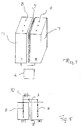
[0019] FIG. 1 is a view showing a perspective view of an apparatus for increasing a concentration of stable water clusters in accordance with one embodiment of the present invention;
[0020] FIG. 2 is a view showing another embodiment of the inventive apparatus, which is composed of several individual units;
[0021] FIG. 3 is a perspective view of one of the units of the inventive apparatus, in accordance with a further embodiment of the invention;
[0022] FIG. 4 is a perspective view of the inventive apparatus, which is composed of two units;
[0023] FIG. 5 is a view schematically showing an electrical circuit of the inventive apparatus illustrated in FIG. 4.


DESCRIPTION OF THE PREFERRED EMBODIMENTS
[0024] In accordance with the present invention, a method and an apparatus are proposed for increasing the concentration of stable water clusters. For this purpose, water or water solution is used, which contains the stable water clusters that are made as disclosed for example in our U.S. Pat. Nos. 8, 193,251 and 8,383,688. Thereafter the new inventive method and apparatus is utilized to increase the concentration of the stable water clusters.
[0025] In accordance with the present invention, an external electric field is applied to the water solution that contains the stable water clusters. As a result, alignment of the stable water clusters will occur along a direction of the external electric field. The stronger the external electric field, the more aligned are the stable water clusters. When the stable water clusters are aligned, an internal electric field is formed because the dipole moments of the stable water clusters combine. Water molecules adjacent to the stable water clusters align and become attracted firmly to the existing stable water clusters to form a part of new, enlarged stable water clusters. In this way, under the action of the strong external electric field, the stable water clusters grow larger.
[0026] The external electric field can be applied to the water solution with the stable water clusters accommodated in a container, for example, by means of two plates between which the container is located, or by means of wires introduced into the container, or by means of wires introduced in the container in combination with the plates located outside of the container.
[0027] In order to speed up the process of growth of the stable water clusters, it is desirable to increase the number of the stable water clusters in the water solution. In accordance with the present invention, this can be done by vigorous shaking of the container which contains the water solution with the stable water clusters. This vigorous shaking can be produced by generating ultrasound vibrations of the container. For example, an electrical transducer can be connected with the container and generate ultrasound vibrations of the container and thereby shaking of the water solution with the stable water clusters accommodated in the container.
[0028] In accordance with the invention, with the combination of the strong external electrical field and mechanical, for example ultrasound, shaking, a much higher concentration of the stable water clusters with a larger size is achieved.
[0029] FIG. 1 shows an apparatus for applying external electrical field to the water solution with the stable water clusters in accordance with one embodiment of the invention. The apparatus has a container, formed for example as a rectangular glass tank 1 which accommodates the water solution with the stable water clusters contained in it.
[0030] The apparatus further has two plates 2 and 3 which can extend parallel to one another and are spaced from one another to form therebetween a space, in which the tank 1 is located. The tank 1 is filled with water that contains stable water clusters. The plates 2 and 3 are connected with a not shown electric circuit and produce an external electric field applied to the water with the stable water clusters, accommodated in the tank 1. This provides alignment of the stable water clusters and forms an internal electric field because the dipole moments of the stable water clusters combine. Water molecules adjacent to the stable water clusters align and become firmly attracted to the existing stable water clusters. They then become a part of new enlarged stable water clusters, and the stable water clusters grow larger.
[0031] The apparatus further has means for vigorous shaking of the tank 1, which can be formed as an electric transducer 4 applied to the tank 1 and generating ultrasound vibrations. While the electrical transducer 4 is shown here as connected to the tank 1, it is also possible to connect the transducer to the tank 1 through a bath of water. The ultrasound applied to the water with the stable water clusters in the tank 1 breaks up the stable water clusters into smaller ones but with large electric dipole moment. These smaller stable water clusters will grow bigger. Since they are maintained under the strong external electric field, these smaller stable water clusters are aligned and the net electric dipole moment is bigger, and also the addition of extra water molecules to these smaller stable water clusters is easier. Thereby the growth of the smaller stable water clusters into the bigger stable water clusters is faster and there are more of them. The combination of the strong external electric field and ultrasonic shaking creates a much higher concentration of the stable water clusters with larger size.
[0032] FIG. 2 shows a container 5 of the inventive apparatus for carrying out the inventive method, in accordance with a further embodiment. The container 5 can be composed of a plurality of individual units 6, for example of three units, as shown in this figure.
[0033] The external electric field can be produced, in accordance with a further embodiment of the invention, in a different way. FIG. 3 shows a unit 7 of the container of the inventive apparatus, which is provided with wire means. The wire means can include a wire or a plurality of wires 8 arranged inside the unit 7. As shown in FIG. 4, the container has two units 7 with the wires 8 inside them, and a grounded conducting plate 9 located between the units 7. The wires 8 and the conducting plate 9 are connected to a power source 10 as shown in FIG. 5. In particular all wires 8 are connected to the same electrode, while the conducting plate 9 is grounded and serves as an opposite electrode. A positive voltage is maintained between the conducting plate 9 and the wires 8. Most of the potential drop occurs near the thin wires 8.
[0034] It is also possible to provide in the apparatus a single container with a grounded conducting plate located in its interior and insulated from the water in the container, and with wires or sets of wires also located in the interior of the container, and correspondingly connected to a power source.
[0035] During the operation of the inventive apparatus it is recommended to provide a period of the vigorous vibration that is followed by a period of growth without the vigorous vibration.
[0036] One example of operation of the apparatus in accordance with the present invention, which carries out the inventive method is presented hereinbelow.
[0037] A cylindrical glass container was used to accommodate the water solution that contains the stable water clusters. A conducting element which serves as one electrode and was formed as an aluminum foil was applied on the glass container. A platinum wire was inserted into the glass container in the middle of the water solution, and high voltage of 1,000 volt was applied to the wire. The glass container was placed in an ultrasound bath and was shaken intermittently by turning on the ultrasound bath for 30 minutes.
[0038] Table 1 below shows the size and number of the stable water clusters before the shaking and application of 1,000 volt for half an hour. 18 hours later the water solution was measured again. The measurement showed that the total number of the stable water clusters above 0.1 micrometer increases from 331.1 to 984.4333.
[0000]
TABLE 1
LOCATION: 01 Before SAMPLE SIZE: 3 ml SYRINGE: 25 ml TARE: 0.2 ml
Data is CUMULATIVE and NORMALIZED
DATE TIME 0.1 0.15 0.2 0.24 0.3 0.35 0.4 0.5
5/16/12 14:20:22 99266.7 44160 22660 13013.3 5053.3 2073.3 833.3 413.3
5/16/12 14:20:25 99533.3 43566.7 22220 12153.3 4853.3 2073.3 740 326.7
5/16/12 14:20:28 98933.3 43773.3 22986.7 13220 5413.3 2200 713.3 253.3
Run Results
5/16/12 14:20:28 99244.43 43833.33 22622.23 12795.53 5106.633 2115.533 762.2 331.1
Run Complete OK
Bottle 1 Overnight Rest After Treatment
LOCATION: 01 SAMPLE SIZE: 3 ml SYRINGE: 25 ml TARE: 02.ml
Data is CUMULATIVE and NORMALIZED
DATE TIME 0.1 0.15 0.2 0.24 0.3 0.35 0.4 0.5
5/17/12 14:11:56 142020 ? 66326.7 31260 18546.7 9006.7 5053.3 2306.7 986.7
5/17/12 14:11:59 142386.7 65526.7 30380 18200 8886.7 4953.3 2140 913.13
5/17/12 14:12:02 141826.7 65880 30140 17880 9060 5126.7 2380 1053.3
Run Results
5/17/12 14:12:02 142077.8 85911.13 30593.33 18208.9 89.84.467 5044.433 2275.567 984.4333
Run Complete OK
[0039] In accordance with the present invention, also products are proposed, which contain increased concentration of the stable water clusters. These new products can be produced by the inventive method and in the inventive apparatus.
[0040] The new products with the increased concentration of the stable water clusters can be water, a petroleum product such as for example gasoline, diesel fuel, natural gas, a health benefit providing product such as vitamins, minerals, hormones, extracts, as medication for prevention and treatment of diseases, or another product, each containing the increased concentration of the stable water clusters.
Cream
for Applying on a Body
US8575223
US8575223
A cream has at least two components, one of the components includes stable water clusters, and the cream is applied on a body to produce local surface effects, local deep effects, and non-local effects in the body.
BACKGROUND OF THE INVENTION
The present invention relates generally to creams, and in particular to cream for applying on a body of humans and animals.
Creams of these types are known in the art in great varieties. The creams can be applied on a body for purely cosmetic purposes, they also can be applied on the body for health enhancing purposes, and sometimes they can be applied on the body for achieving both above mentioned results. It is believed that the existing creams can be further improved.
SUMMARY OF THE INVENTION
Accordingly, it is an object of the present invention to provide a new cream for applying on a body, which is a further improvement of existing creams.
It is also an object of the present invention to provide a method of health enhancement with the use of the new cream.
In keeping with these objects and with others which will become apparent hereinafter, one feature of the present invention resides, briefly stated, in a cream for applying on a body, which has at least one first component including stable water clusters.
When the cream in accordance with the present invention is applied on a body, in particular on a skin, stable water clusters which have nanometric sizes, easily penetrate the skin and cause health enhancing results which will be explained in detail hereinbelow.
In accordance with a further feature of the present invention, in the inventive cream the stable water clusters of its at least one first component are formed as double-helix water clusters.
It is still a further feature of the present invention that the at least one first component includes a mixture of pure water and water with the above-mentioned stable water clusters.
The cream in accordance with the present invention further includes at least one second component, which is mixed with the above mentioned first component of the cream.
In accordance with a further feature of the present invention, the second component of the inventive cream can be an organic component.
The second component of the inventive cream can include a plant ingredient, or an animal ingredient, or a nutrient supplement ingredient, or various combinations of two or three above mentioned ingredients.
As for the second ingredient of the cream in accordance with the present invention. In the second component of the cream the plant ingredient can include oils, the animal ingredient can include beeswax, the nutrient supplement ingredient can include vitamins.
The present invention also deals with a method of health enhancement, which includes applying on a body a cream which has at least one first component including stable water clusters.
In accordance with the present invention, the cream with the first component including the stable water clusters is applied on a skin of the body of a human or an animal.
In accordance with the inventive method, the cream made in accordance with the present invention can be applied on an area of the skin, which has health problem, in order to alleviate these skin problems.
The cream in accordance with the present invention can be also applied on the skin so that it penetrates the skin and enhances health of internal organs of the body, such as muscles, tissues, bones.
The cream in accordance with the present invention can be also applied on acupoints and dispersed throughout the body so as to enhance health of internal organs and systems in correspondence with respective acupoints.
The novel features of the present invention are set forth in particular in the appended claims.
The invention itself, however, both as to its construction and its method of operation, is disclosed in detail in the following description of the preferred embodiments.
DESCRIPTION OF THE PREFERRED EMBODIMENTS
With the present invention, a new cream for applying on a body of a human or an animal is proposed. The cream in accordance with the present invention has at least one first component including stable water clusters.
The stable water clusters are produced as disclosed in our patent application Ser. No. 12/592,873 filed on Dec. 3, 2009, which is now U.S. Pat. No. 8,193,251 issued on Jun. 5, 2012. The stable water clusters are those stable water clusters which are disclosed and described in detail in our patent application Ser. No. 12/592,877 filed on Dec. 3, 2009, whose description is incorporated herein by reference thereto.
The cream in accordance with the present invention is used for applying on a body, in particular on a skin, and the stable water clusters which are contained in it and have nanometric sizes, easily penetrate the skin and produce health enhancing results.
In the inventive cream the stable water clusters which are contained in its at least one first component can be double-helix water clusters. It is to be understood however that the stable water clusters of other configurations can be also utilized in the first component of the cream.
The at least one first component includes a mixture of pure water and water with the above-mentioned stable water clusters. The pure water is preferably a very pure water which has 16 mega ohm or better resistance with low total organic carbon less than 100 ppm, and it mixed with the water which contains the stable water clusters. The amount of the water with the stable water clusters in the cream in accordance with the present invention is preferably 40% or less by weight from total weight of the cream.
The cream in accordance with the present invention further includes at least one second component, which is mixed with the above mentioned first component of the cream. The second component of the inventive cream preferably can be an organic component.
The second component of the inventive cream can include a plant ingredient, an animal ingredient, a nutrient supplement ingredient. It can also various combinations of two or three of the above mentioned ingredients, which are mixed with each other.
When the second component of the cream is a plant ingredient it can include for example oils. When the second component of the cream is an animal ingredient it can include for example beeswax. When the second component of the cream is a nutrient supplement ingredient it can include for example vitamins. The oil for example can be coconut oil, sweet almond oil, lecithin, etc, and various combinations thereof. The vitamin for example can be vitamin E, another vitamin, and various combinations thereof.
The cream in accordance with the present invention, in addition to the above mentioned first and second components, can also include small amounts of scent, or fragrance, or preservatives, which are known per se in the art.
In order to make the cream in accordance with the present invention, first water with stable water clusters is made in a manner described in detail in our above mentioned patent applications and patent, and then mixed with very pure water, so as to produce the first component of the cream. Then the second component of the cream is produced by mixing its ingredients. The water mixture of the ingredients of the first component is warmed up, the mixture of the ingredients of the second component is heated up and added to the first component, the thusly produced mixture is stirred and heated together until the inventive cream is formed. It is then cooled down to room temperature and is ready to either be stored, or packed into individual containers for consumption.
It should be mentioned that the temperature of the mixtures of the first and second components should be greater than the freezing temperature of water (0° C.) and lower than the boiling temperature of water (100° C.), so that its water component remains in liquid state.
The cream in accordance with the present invention is used for health enhancing purposes of a human body or an animal body. In accordance with one embodiment the cream is used to achieve an effect which is local and on a surface. In this case the inventive cream is applied substantially on an area of the skin which has skin problems. In this case the cream may be used for baby rash on buttocks, for a mosquito bite on a face, for itches on the skin, for burns of the skin, etc. The cream for a respective one of the above mentioned health problems can have a slightly different composition. In the case this local and surface application of the cream, it can be also used for cosmetic purposes to produce a smooth and better looking skin.
The cream in accordance with the present invention further can be used to produce local deep effects in the body. In this case the cream is rubbed to reach a corresponding depth to penetrate through the skin and into desired organs of the body. In this embodiment the cream produces health enhancing effects for example on such organs as muscles, tissues, bones. In this case it can be also efficiently utilized for sport use.
In accordance with a further embodiment of the invention, the inventive cream can be also used for non-local effects. In this case it can be applied on acupoints and rubbed in there, so that it is dispersed throughout the body via meridian system. For example, is the inventive cream is rubbed on the acupoint ST4 near the mouth, it will have an effect on stomach and digestive system.
One example of the cream in accordance with the present invention is presented in the Table hereinbelow.
TABLE 1
Components Quantity
Bees Wax 2.5 ounces
Coconut Oil 2 ounces
Sweet Almond Oil 6 ounces
Ultra Pure Water With
1.5 fl. oz. of Water With
Stable Water Clusters 6.5 ounces
Lecithin 2,400 mg
Vitamin E Oil 400 IU.
Water
clusters, products with water clusters, and methods of
producing
US8383688
US8383688
BACKGROUND OF THE INVENTION
The present invention relates to water clusters and products containing them.
Water clusters and methods of their manufacture and use are known in the art.
They are disclosed for example in Proceedings of First International Conference of the Physical, Chemical and Biological Properties of Stable Water Clusters, edited by B. Bonavita, S. Y. Lo, World Scientific 1997, and in U.S. Pat. Nos. 5,800,576; 5,997,590; U.S. patent application publication 2006/0110418, international patent application publication WO 2009/04912, U.S. patent application publication 2005/0270896, U.S. Pat. No. 6,487,994, U.S. patent application publication 2004/0025416.
It is believed that the known water clusters and products containing them can be further improved.
SUMMARY OF THE INVENTION
Accordingly, it is an object of the present invention to provide improved products containing water clusters.
In keeping with these objects and with others which will become apparent hereinafter, one feature of the present invention resides, briefly stated, in a product, comprising solid stable water clusters including a plurality of water molecules connected with one another by electrical dipole interaction via internal electric field of ions and having a permanent electric dipole moment with an electrical field surrounding the solid stable water clusters.
The stable water clusters have nanometer sizes.
In accordance with the present invention resides the solid stable water clusters are stable under normal room and atmospheric pressure.
In accordance with the present invention a product can contains water with solid stable water clusters in the water.
In accordance with the present invention a product can contains a petroleum component with said solid stable water clusters, wherein the petroleum component can be a component selected from the group consisting of gas, diesel, and natural gas.
A further feature of the present invention resides that in a product can contain a skin care component with the solid stable water clusters contained in it.
In accordance with the product contains a component providing health benefits, with stable solid water clusters contained in it, and the component providing health benefits can be a component selected from the group consisting of vitamins, minerals, hormones and extracts.
A further feature of the present invention resides in that the product can contains solid stable water clusters in form of an emulsion that contains a suspension of small water droplets that include said solid stable water clusters.
That the solid stable water clusters have a ring-shaped structure, selected from the group consisting of pentagon, a hexagon, and a rectangle.
A plurality of ring-shaped structures of said solid stable water clusters can be joined together to form a larger structures of said solid stable water clusters.
In accordance with a further feature of the present invention a solid stable water clusters can be arranged in a form of a double helix.
The solid stable water clusters can be produced by connecting a plurality of water molecules with one another by electrical dipole interaction via internal electric fields of ions to provide the solid stable water clusters having a permanent electrical dipole moment and nanometers sizes.
The production process can include multiple dilution of a material with pure water.
BRIEF DESCRIPTION OF THE DRAWINGS
FIGS. 1 and 2 are atomic force microscope pictures of solid stable water clusters;
FIG. 3 is a view showing schematically a device for producing solid stable water clusters;
FIGS. 4-7 are atomic force microscope pictures of residues from dried sodium chloride solution for producing solid stable water clusters;
FIG. 8 is a view showing schematically a device for a small scale production of solid stable water clusters;
FIGS. 9 and 10 are atomic force microscope pictures of residues of another embodiment for producing solid stable water clusters;
FIGS. 11 and 12 are views schematically showing processing of petroleum fuel to be mixed with a catalyst based on solid stable water clusters;
FIG. 13 is a view showing microscope pictures of sodium chloride crystals;
FIGS. 14-16 are atomic force microscope pictures of solid stable water clusters with different structures;
FIGS. 17-20 are views showing various shapes of solid stable water clusters;
FIG. 21 is a view showing a picture of DNA with a double-helix structure;
FIGS. 22-23 are atomic force microscope pictures of solid stable water clusters in a double-helix structure.


DESCRIPTION OF THE PREFERRED EMBODIMENTS
New methods for production of water clusters will be now described in detail.
It is known that ordinary water contains clusters which consist of water molecules. These variable water molecules are often called flickering-water-clusters because the hydrogen bonds are broken randomly by thermal energy and then recombine. The present invention deals with sold solid stable water clusters which are made of a fixed number of water molecules having a steady stable electric field surrounding them.
Solid stable water clusters can be created in accordance with the present invention by diluting soluble substances into ultra-pure water.
Such solid stable water/clusters range in size from tens of nanometers to a few microns in size. These have a permanent electric/dipole/moment. There is strong electric field surrounding them.
FIG. 1 shows an atomic force microscope picture tapping of one such sold solid stable water clusters where the electric field is explicitedly measured by its corresponding photo taken using the electric force mode of the same microscope. The sample consists of ultra-pure water containing many solid stable water clusters onto highly-ordered pyrolytic graphite. The atomic force microscope picture was taken by a tapping mode where physical contact is made on the first pass of the scanning device, but on the second pass the tip is held above the surface at a distance of 100 nanometers with a 1 volt bias is placed on the scanning tip, thus producing an electric force mode picture as in FIG. 2 as the tip then becomes effected by the electric field of the solid stable water clusters.
The largest solid stable water clusters are of micron size and are made from combinations of smaller solid stable water clusters that range in size from tens to hundreds of nanometers. One size distribution of these solid stable water clusters is shown here. In this ultra-pure water containing solid stable water clusters, the Lighthouse Model L-S60 Liquid Sampler is used to shown the clusters in the following distinct sizes: 0.1, 0.5, 0.2, 0.25, 0.3, 0.35, 0.4 and 0.5 Microns.
Solid Stable Water Clusters
Distribution
0.1 0.15 0.2 0.25 0.3 0.35 0.4 0.5
1179 2377.7 2208.7 1530 343.7 156.7 325 1173
Since the smallest solid stable water clusters are measured in nanometers, they are distinct from earlier emulsion products which were used before.
The strong electric fields surrounding these solid stable water clusters will increase the speed of chemical reactions, hence they can be used as catalysts.
It is well known that oil and water do not mix naturally by themselves. There are ways to bind oil with water as a stable product; either form an emulsion via ultra-sound or vigorous shaking or to add chemical binders, or a combination of both.
However, there is a practical problem of how to introduce these solid stable water clusters into combustion fuels which feed combustion engines of all types. It is necessary to break up the solid stable water clusters into their smaller components for the best catalytic effect. The nanotechnology emulsion method proposed here suspends nano-sized solid stable water clusters directly in all petroleum based fuels such as diesel, gasoline, jet fuel, etc. without adding additional chemicals such as binder and combustion enhancers.
Water/clusters have not been made part of petroleum fuels with a nano-emulsion requiring no more than 3 parts per million of sold stable water clusters waters.
FIG. 3 shows an actual production device. One tank is the supply, where diesel is placed. It is pumped through a vertical ultra-sound shaft into a treatment tank to create a nano-emulsion.
Thus an additive for fuel is a solution that contains solid stable water clusters made from water molecules. The solution is a special emulsion that contains a suspension of small water droplets of submicron size. The emulsion is created via vigorous shaking of water that contains sold stable water clusters and petroleum products such as diesel fuel, gasoline, and jet fuel using ultrasound device. The emulsion is added to the fuel of combustion engines and the like, gasoline, diesel, natural gas, etc., which combustion engines can be in trucks, cars, ships, airplanes, locomotives, or electricity generating plants.
A skin care product in accordance with the invention can include a solution that contains solid stable water clusters in accordance with the invention. The solution can be an emulsion that contains a suspension of small water droplets which contain the solid stable water clusters in other non-water-soluble liquids. The non-water-soluble liquids can be liquids selected from the group consisting of oil and a cream.
The skin care products described above can include additional chemicals. On the other hand in the skin care product in accordance with the invention no chemicals can be added. The emulsion for the skin products can be an emulsion generated via vigorous shaking of water that contains solid stable water clusters, and water droplets can be of submicron size.
The skin care products in accordance with the invention can include ingredients having health benefits. The ingredients can include vitamins, minerals, hormones, natural herbal extracts, etc.
A food product in accordance with the invention contains inventive solid stable water clusters. The solution can be an emulsion that contains a suspension of small droplets the solid stable water clusters in other non-water-soluble liquids. The food product can contain additional substances, or no substances can be added. The water droplets are submicron size. The above-mentioned emulsion can be generated via vigorous shaking of water that contains the solid stable water clusters.
Numerous food products can be produced with the use of the solid stable water clusters and corresponding food ingredients. Also drinking and non-drinking water can be produced such that it contains the inventive solid stable water clusters.
Solid stable water clusters can be produced by diluting organic and/or inorganic material with very pure water. It is necessary to dilute the inorganic materials to a certain dilution before it is possible for the stable water clusters to form. It is also necessary to use 18.2 MO*cm million ohms per centimeter quality water as the dilution water in order to have the largest amount of stable water clusters. Within the ultra-pure water industry, equipment is available to purify water to 18.2 MO*cm of resistance.
An additional criteria is used to ensure the highest possible quality. The Light House LS-60 laser particle counter allows an analysis of the number of particles per unit volume present. The proper use of containers is ensured thus controlling the leaching or contamination from other chemicals or particles which could be present in the containers themselves. The two types of containers that are used in the inventive method are composed of quartz and polypropylene or similar materials.
Distilled commercially available water has typical 50 thousand 0.1 micron particle or large counts per 1 ml samples. The inventive method uses ultra-pure water that has particle counts less than 500 particles per 1 ml above 0.1 micron. See Table 1 below as a comparison of commercially available distilled water and our ultra-pure-water.
The ultra-pure water is labeled “10-Water” and is the water that is used with the inventive method. Measurements are from 0.1 microns to 0.5 microns.
TABLE 1
Comparison of Commercially available distilled water to our ultra-pure “10 Water”.
Distilled water
Location: 01 SAMPLE SIZE: 1 SYRINGE: 25
Data is CUMULATIVE and NORMALIZED
Date Time 0.1 0.15 0.2 0.25 0.3 0.35 0.4 0.5
Mar. 1, 2009 16:15:59 56180 18540 6760 3720 1620 1040 860 660
Mar. 1, 2009 16:16:00 56220 18840 7280 4140 1660 1020 840 660
Mar. 1, 2009 16:16:01 56780 18540 7060 4200 1880 1320 1060 860
Run Results
Mar. 1, 2009 16:16:01 56393 18640 7033.3 4020 1720 1126.7 920 726.27
“10 Water”
LOCATION: 01 SAMPLE SIZE: 1 ml SYRINGE 25 ml TARE: 0.2 ml
Data is CUMULATIVE and NORMALIZED
Date TIME 0.1 0.15 0.2 0.25 0.3 0.35 0.4 0.5
Mar. 1, 2009 16:02:05 20 0 0 0 0 0 0 0
Mar. 1, 2009 16:02:06 20 0 0 0 0 0 0 0
Mar. 1, 2009 16:02:07 20 0 0 0 0 0 0 0
Run Results
Mar. 1, 2009 16:02:07 20 0 0 0 0 0 0 0
Run Complete OK
Therefore the first step of the inventive method is the production of “10-water” to use as the dilution water to create stable water clusters.
Next the process of dilution is carried out in an Argon gas filled chamber. It is important to carry out the entire procedure in an atmosphere free of carbon dioxide. Pure 18.2 Mohm water will degenerate rapidly to 1 Mohm water or less in a matter of seconds when it is exposed to normal atmosphere due to the presence of carbon dioxide. Such an exposure of ultra-pure water to CO2 will form carbonic acid thereby producing ions to conduct electricity.
Therefore, the dilution in accordance with the invention is carried out by adding a small amount of materials to the “10-water” in the Argon filled gas chamber. In the following example, sodium chloride is used:
In table 2 the particle size distribution of sodium chloride solution with concentration of 10 to the minus 3 Mole is shown.
TABLE 2
Ten to the minus 3 Dilution of NaCl made with “10 Water”
Location: 01 SAMPLE SIZE: 1 ml SYRINGE: 25 ml
Data is CUMULATIVE and NORMALIZED
Date Time 0.1 0.15 0.2 0.25 0.3 0.35 0.4 0.5
Mar. 1, 2009 16:14:21 26880 10060 5740 4040 2600 2160 1840 1540
Mar. 1, 2009 16:14:22 27340 9640 5820 4020 2800 2220 1840 1520
Mar. 1, 2009 16:14:23 27140 9780 5660 4120 2900 2240 1860 1460
Run Results
Mar. 1, 2009 16:14:23 27120 9826.7 5740 4060 2766.7 2206.7 1840 1506.7
Run Complete OK
In Table 2 the particle size distribution of sodium chloride solution is shown with concentration of 10 minus 3 Mole made from “10 Water”. Dilution with “10 water” to 10 to the minus 7 under controlled non-atmosphere conditions equates to a linear downward diminishing of particles to a total of 2.7 total particles.
Notice should be made that when that same solution is diluted further to 10-7 M, particles of larger than 0.1 microns appear much more than the readings for 10-3. Since they cannot be ions, they can only come from the formation of water molecules into clusters that were detected.
1.7 times 10 to the minus 7 NaCl
Location: 01 SAMPLE SIZE: 1 ml SYRINGE: 25 ml TARE: 0.2 ml
Data is CUMULATIVE and NORMALIZED
Date Time 0.1 0.15 0.2 0.25 0.3 0.35 0.4 0.5
Mar. 1, 2009 16:09:27 3680 1020 340 120 20 20 20 20
Mar. 1, 2009 16:09:28 3680 1200 440 300 100 40 40 40
Mar. 1, 2009 16:09:29 3280 900 260 120 60 40 40 0
Run Results
Mar. 1, 2009 16:09:29 3546.7 1040 346.67 180 60 33.333 33.33 33.333
Run Complete OK
Atomic force microscope AFM pictures are taken and shown in FIG. 4 Tapping, Topo frw, NaCl crystal FIG. 4 shows pictures of residues from dried 10 times the minus 3 mole sodium chloride solution that show the crystalline form of sodium chloride
FIG. 4 shows an atomic force microscope picture of the residue of Solution S after evaporation of liquid residue. The shape and size of stable water clusters in Solution S can be explicitly seen. Solution S is defined as the solution obtained by dilution of small amount of materials.
FIG. 5 Tapping Phase bkw EFM, NaCl crystal shows electric force microscope pictures of residues from dried 10 to the minus 3 Mole sodium chloride solution taken simultaneously with FIG. 4. The uniform color on the NaCl crystalline form indicates that there is no charge on the surface of the sodium chloride. At the right side of the picture the vertical edge indicates charge present from contamination on the microscope stage but no charge on the sodium chloride crystal.
FIG. 6 Tapping Topo Frw, 1.7 e-7 diluent shows atomic force microscope pictures of residues from dried 1.7×10⁻⁷ M sodium chloride solution which illustrates the shape of stable water clusters and not the shape of the crystalline form of sodium chloride.
FIG. 7 Tapping Phase bkw, 1.7×e-7 diluent shows electric force microscope pictures of stable water clusters demonstrating that the crystalline structures are changed.
These water-clusters prepared with the above method from very dilute solutions are stable over a period of days, months, and years. The water clusters are especially stable.
The dilution process to make stable water clusters can be carried out in either small or large scale batches; a small scale batch can be done in liter or gallon containers whereas large scale batches can be done in containers for hundreds of gallons or more.
Small scale production is shown in FIG. 8, for the production of stable water clusters in a gallon container. The container, tubes, stoppers, etc., are made of polypropylene to minimize leaching problem that produces contamination of the product. The stopper on the top of the container has three holes for three tubes. The tube 1 allow argon to flow in, the tube 4 allows argon to flow out, allowing a positive argon gas pressure relative to normal atmosphere so that no air can flow in to contact the solution. This prevents the carbon dioxide contamination to the pure 10-water, or the final production solution.
The device can be scaled upward for mass production and can be automated for continual service.
The process takes place in the following manner:
Argon comes in from the Tube 1 and pushes all atmosphere within the bottle out through the Tube 4,
“10 Water” is injected from the tube 2 in the middle into the bottle that is devoid of atmosphere and filled with Argon;
As “10-Water” enters the bottle, a tiny amount of Substance A is sucked into the bottle by Venturi effect at Ventur Tube 3, thereby allowing the dilution of Substance A to occur in an environment where no carbon dioxide is present and “10 Water” can maintain its purity.
Thus this production process of creation of stable water clusters includes adding a small amount of Material A in water, the purity of which is characterized by a resistivity of 18.2 Mohm and very small number of impurities, as measured by laser particle counter. The dilution process is carried out in carbon dioxide free atmosphere. The dilution process can be carried out in the presence of an inert gas, such as argon gas. The dilution process can be carried out in a bottle that is filled with argon gas and maintained at positive pressure so that no atmosphere will leak in. All the containers are leak and leach free vessels allowing no impurity/contaminants of any kind to contaminate the pure water or the very dilute solution where stable water clusters are created. The containers contain three outlet tubes on the top: one tube that argon flows in, one tube that argon flows out, and the third tube for pure water to add to the container. The third tube where pure water flows can suck in a small amount of dilute solute by Venturi effect. The dilution process is carried out without contact with normal air. The containers, tubes, stoppers, etc., are made of polypropylene or quartz or similar materials which prohibit contamination. The materials A can be any organic, or inorganic materials artificially created or found, or isolated from plants, animals, and humans, such as vitamins, amino acids, hormones, proteins, enzymes, polypeptides, polysaccharide, DNA, RNA etc. The solution from dilution can be used to enhance combustion for fuel, to improve health to enhance biochemical reactions, in industrial catalytic processes of all kinds, for the enhancement of textiles, to enhance electroplating and similar processes.
The production of stable water clusters in large scale by dilution of materials into very pure water was described above. It is often desirable to have a more concentrated solution with a much larger number of stable water clusters that normally obtainable through dilution of a single material into very pure water. In accordance with the invention it is proposed to enhance the production of stable water clusters to increase the number of clusters per unit volume.
It starts with a very dilute “Solution S” of some material A. As an example sodium chloride is used as material A. Material A is diluted with very pure water to a concentration of 1.7 times 10?<7 >mole prepared under strict conditions as discussed above. The number of stable water clusters in the Solution S can be measured by a laser particle counter such as a Lighthouse Liquid Particle Counter LS-60 and those results are shown in Table 3.
1.7 times 10 to the minus 7 NaCl
LOCATION: 01 SAMPLE SIZE: 1 ml SYRINGE 25 ml TARE: 0.2 ml
DATA is CUMULATIVE
DATE TIME 0.1 0.15 0.2 025 0.3 0.35 0.4 0.5
Mar. 1, 2009 16:09:27 3680 1020 340 120 20 20 20 20
Mar. 1, 2009 16:09:28 3680 1200 440 300 100 40 40 40
Mar. 1, 2009 16:09:29 3280 900 260 120 60 40 40 40
Run Results
Mar. 1, 2009 16:09:29 3547 1040 346:7 180 60 33.3 33.3 33.3
Run Complete OK
Table 3 shows particle counts of various sizes from 0.1 micron to 0.5 microns from a very dilute sodium chloride Solution S of concentration 1.1×10<-7 >mole prior to concentration method discussed below.
FIG. 9 shows an atomic force microscope picture of the residue of Solution S after evaporation of liquid residue. The shape and size of stable water clusters in Solution S can be explicitly seen.
The number of stable water clusters can be increased in the very dilute Solution S by adding a second material that has a permanent electric dipole moment. Using small droplets of the second material designated as Material B, the material B has been diluted below 1.0×10<2 >mole; Material B is then added to Solution S in small droplets.
Material B could be vitamin E or omega 3 oil, or any other organic or inorganic material or the mixture of many different kinds of materials. As a specific example, omega 3 oil is used as Material B.
A very small amount of omega 3 oil is used and mixed with very pure water, preferably under surrounding argon gas. Since oil and water do not mix, additional processing is needed to mix oil and water. For thorough mixing ultrasound vibration is used so as Material B will be pulverized into a colloidal suspension. For maximum effect the oil molecule must be in contact with water molecules directly. Oil will not go into solution with water but rather together they form an emulsion. Then a small amount of this thoroughly mixed emulsion of Material B and pure water is added into Solution S. The final Solution S' should have a minute concentration of Material B in the range of 1.0×10<-7 >mole.
The surface of the new organic molecule (omega 3 oil) will have many positively and negatively charged spots. Surrounding water molecules and stable water clusters will attach to these charged spots and these charged spots will provide growth sites for the stable water clusters. New stable water clusters will grow and existing stable water clusters created by material A will grow larger. The result will be a solution higher in concentration of stable water clusters per given volume.
Table 4 presents the distribution of the sizes of stable water clusters as counted by laser particle counter for Solution S' with the addition of Material B using the method herein described. An increase of stable-water-cluster per given volume is shown:
Enhanced Solution S with Material B
Location: 01 SAMPLE SIZE: 1 ml SYRINGE: 25 ml TARE: 0.2 ml
Data is CUMULATIVE and NORMALIZED
Date Time 0.1 0.15 0.2 0.25 0.3 0.35 0.4 0.5
Mar. 1, 2009 16:29:08 163260 147920 112620 81360 44100 31800 26460 20500
Mar. 1, 2009 16:29:09 163720 148300 113780 81080 2880 31060 25640 20120
Mar. 1, 2009 16:29:10 161900 147867 112560 80713 43293 31467 26200 20420
Run Results
Mar. 1, 2009 16:29:10 162960 147867 112560 80713 43293 31467 26200 20420
Run Complete OK
Table 4: shows particle counts of various sized stable water clusters from 0.1 microns to larger than 0.5 microns from Solution S' after performing the enhancing discussed herein.
FIG. 10 shows the pictures from atomic force microscope of the residues obtained from dehydrated Solution S' after process of enhancement is complete (Tapping, Topo Frw, 1.7×3-7 diluent). The size and distribution of stable water molecules are explicitly displayed.
Thus in this method an enhanced Solution S' is produced from an existing Solution S, which is known to have stable water clusters by adding small amount of a second Material B to Solution S, whereas the Solution S' will increase in the number of stable water clusters. The material B is liquid phase, which may be inorganic or organic. It can be is one of the petroleum products, diesel, gasoline, or its derivatives. The Material B is first thoroughly mixed with very pure water by vigorous shaking such as ultrasound shaking to form a uniform mixture, which is an emulsion. A small amount of the uniform mixture is added to very pure water under the argon gas. The very pure water comes from a water producing machine that produces water with very high purity as measured by resistivity meter to be close to 18 Mohm-cm. Each step of production process and not any part of the solution is ever exposed to carbon dioxide in the air. All the containers, tubes, stoppers, joints are made of materials, which do not leak or leach when in contact with very pure water. Examples of such materials are quartz and polypropylene. The enhanced Solution S' of stable-water-molecules can be used to be a fuel catalyst in combustible fuel such as gasoline, diesel, natural gas, jet fuel, heavy oil, and coal, to reduce coking in processing plants in oil refineries, power plants, manufacturing facilities that produces petroleum derived products, for health purposes such as supplements, medicines, or energized homeopathic remedies, in industrial processes such as the manufacture of nitrogen fertilizer. In industrial processes which require the use of water to enhance or suppress the enzymatic effect on bioactivities such as fermentation, to change or strengthen textiles, to improve the function and life of acid lead batteries.
In accordance with a further embodiment of the invention the following device can be used for industrial large-scale production of products containing a catalyst made from stable water clusters.
FIG. 11 shows the device that includes a feeder tank A on the right with diesel fuel. The diesel fuel is pumped to tank B, where an ultrasound vibration device is installed. Before the fuel reaches tank B, a small amount of concentrate catalyst CC is extracted from tank C by Venturi effect. The ratio R of c concentrate catalyst CC to diesel fuel is set to be very small, such as 1 part CC to 1000 part diesel. The concentrated catalyst CC is mixed thoroughly with diesel fuel in tank B by ultrasound vibration. The flow rate in and out of tank B is controlled to ensure a given amount of ultrasound vibration mixing time to achieve a thorough mixing of CC with the diesel. The mixture of CC plus diesel fuel flows out of tank B and reaches the main tank D. Usually the mixing requires more than one pass through tank B. Then a second round of mixing is achieved by pumping continuously the mixture of diesel and CC form the main tank D back through bank B, for further ultrasound vibration mixing, then back to main tank D.
When the mixing is satisfactorily completed and the diesel fuel is considered to have the necessary catalyst added, it is ready to go to the storage tank E for shipping and distribution to users of diesel fuel. Similar procedure can be applied to gasoline, jet fuel, kerosene or other liquid petroleum products.
While FIG. 11 shows a flow diagram for processing large quantity of petroleum fuel to be mixed with a liquid catalyst without chemical binder, FIG. 12 shows a flow diagram of the addition of concentrate catalyst CC from Tank C through Venturi to Tank B.
Concentrate catalyst CC enters from tank C. Venturi meter valves allows CC to enter into tube carrying fuel toward tank B ultra-sound. Meter tube measures the volume V1 of CC to be mixed with diesel of volume V2. The volume of diesel V2 is controlled by a valve coming from the feeder tank A. The ratio R=V1/V2 is fixed. One way valve allows CC to go into the tube by Venturi effect to mix with diesel coming out from tank A into tank B. Diesel coming out from tank A to flow into ultrasound tank B.
In summary the procedure for producing large quantities of catalyst CC for processed fuel by mixing vigorously a small amount of concentrate catalyst CC with diesel or like petroleum based fuels can be expressed as a formula:
CC+D=CD
where the ratio R is defined by the amount of CC to D by R=CC/D. As an example the ratio is chosen to be 1/1000 in one case.
The method and equipment disclosed can be used generally with any concentration of CC. CC would contain a significant amount of stable water clusters to be mixed with any solution D, such as diesel, gasoline, oil, alcoholic products or the like or to make hand cream, face cream or any health product.
To have a maximum effect of mixing and to ensure the purity of the product produced, the entire system from tank A to tank B, C, D and E would be maintained under a positive pressure of argon gas so as to eliminate the contamination from carbon dioxide and oxygen that would be present in normal room atmosphere.
Some specific examples are presented below for producing a large amount of dilute liquid CD which contains a lower density of stable water clusters from mixing concentrate CC with liquid D.
D is diesel fuel, and CD is a fuel additive to be added to diesel fuel to enhance combustion and reduce pollution.
D is gasoline, and CD is a fuel additive to be added to gasoline to enhance combustion and reducing pollution.
D is any fuel, such as jet fuel, or kerosene, and CD is the fuel additive for jet fuel and kerosene.
D is oil, and CD is oil with stable water clusters that can be used for hands, face, etc., for the enhancement of look and health.
D is pure water, and CD is water with small amount of stable water clusters the can be used for health purpose.
D is wine and CD is wine with a small amount of stable water clusters that can be used as higher quality wine.
Summarizing this embodiment it should be mentioned that the thusly produced large quantities of CD could be a catalyst or oil, or cream, produced by mixing vigorously a small amount of concentrate CC which contains a high density of Stable water clusters with a solution D which can be diesel, gasoline, oil, water or cream to form a dilute solution CD which could be a catalyst for diesel, gasoline or other petroleum fuel or cream. The mixing is done by ultrasound, the mixing ratio R of CC to D can be set to be a small amount, such as 1/1000, the ratio can be maintained by two automatically controlled valves, where the first valve controls the amount of D from feeder tank A, the second valve controls the amount of CC entering into the meter region, where CC is mixed with D by Venturi effect. The mixed and dilute liquid CD is pumped from the said ultrasound tank into the main tank, the mixed CD in the main tank is pumped to go through the ultrasound tank continuously for a short duration so that the mixture CD is thoroughly mixed and stays in the main tank. The thoroughly mixed liquid CD enters into a storage tank E, ready for shipment.
The thoroughly mixed liquid CD can be used as fuel additive, whereas the fuel D can be diesel, gasoline, kerosene, jet fuel, etc.; as health purpose, whereas the said D is oil, and CD can be some emulsion or liquid form for health purpose such as for hands, face, etc.; as an alcoholic beverage whereas D can be any alcoholic beverage, such as wine, beer, etc.; the liquid D can be pure water, and CC is concentrate for some special stable water clusters C, whereas the end product CD is for health uses, such as drinking.
The solid stable water clusters produced in accordance with the present invention have specific molecular structures.
As explained above, it is possible to create stable water clusters by dilution. The dilution of sodium chloride is used as an example. The dilution of both organic and inorganic materials in ultra pure water will produce stable water clusters.
The existence of stable water clusters is revealed by letting stable water clusters water or referred to as cluster water evaporate on a glass slide and then examining the residue left. This is done by light microscope and atomic force microscope. FIG. 14 shows one of the solid stable water clusters. There are various shapes of stable water clusters. Some of them look like cotton balls. In FIG. 14 several ring-like structures can be seen, which can be considered to be more fundamental.
In FIG. 14 the dimensions of the photo are 7.67 micron×7.67 microns. The ring-like structure shown in the picture is approximately 1 micron size.
In solid state physics, when the phenomena of phase transition is considered, an important principle is scaling. The interaction is energy, which is called the Hamiltonian in its operator formalism, scales. That is, the same kind of interaction occurs, no matter what the size of the object. FIG. 13 shows the shape of sodium chloride in various sizes shown in microscope with a magnification of 400×.
The two left-most clusters of sodium chloride crystals can be noticed. The face-centered cubic structure of sodium chloride shows itself as a square shape in the illustrated two dimensional pictures. The smallest to the largest square shaped sodium chloride cubic structure spans a factor of approximately 100. The face-centered cubic structure of sodium chloride remains even down to nanometer size. In comparison, the scaling of the ring-like structure will likewise go down to nanometer size.
There are occasions when the ring-like structure is not complete, but is only half complete. Then kidney-like structures are formed as shown in FIG. 15. In FIG. 15 picture the dimension is 1.66 micron×1.66 microns. Kidney-like structure is approximately 600 nm to 700 nm.
When the residue from evaporated cluster water is examined with atomic force microscope at size below one microns, some more precise pictures can be seen. One of such pictures is shown in FIG. 16. There are pentagons, with five side, hexagons with six sides, rectangle with four side. A group of pentagons and hexagons sometime form into soccer-ball-like structure. In FIG. 16 the picture dimension is 0.63 micron×0.63 microns. Many four, five and six sided ring structures can be seen. These structures range from approximately 30 nm to 50 nm in size. These structures combine to form soccer-ball-like patterns.
The lone pair shown in FIG. 17, where water molecule is composed of two hydrogen atoms and one oxygen atom. These three atoms occupy the vertex of a tetrahedron.
When many water molecules combine together to form a cluster, it is equivalent to hooking many tetrahedrons together. The lowest energy states for water clusters seem to point to pentagon and hexagon configurations, with oxygen molecules occupying the vertices of the pentagons, hexagons, and sometimes rectangles. By doing so, these pentagons and hexagons will form a soccer-ball-like configuration, as shown in FIG. 18. Mathematically they can be presented by:
5<n>6<m >
where n and m indicate the number of pentagons and hexagons that constitutes a soccer-ball-like configuration. For the smaller soccer-ball-like configuration, the vertex, where two lines meet, is the site of the oxygen atom. The hydrogen atoms are spread along the line joining the vertices. In general it may have four side polygons, and it may not even have a closed cage structure like a soccer ball. It is simply the various combination of pentagons, hexagons, and four side polygons. It is represented by:
5<n>6<m>4<k>,
where there are additional k number of four side rectangles. Furthermore, these are only units that can be constructed into the linear shape, helix shape, etc.
FIG. 18 shows balls with sixty vertices, while FIG. 19 shows a soccer ball with 20 hexagons white patches and 12 pentagons black patches, which can be denoted as 5<12 >6<20>.
The most elementary ring structures are represented by the five-sided pentagon, six-sided hexagon, and four-sided rectangle, as shown in FIG. 20. The smallest molecular ring structures are composed of individual oxygen atoms occupying the vertices of these polygons and individual hydrogen atoms spreading along the lines joining these vertices.
FIG. 20 shows the symbolic ring structures of stable water clusters: from left to right; the pentagon; the hexagon; and the rectangle.
Thus the stable water clusters of the present invention are stable under normal room temperature and atmospheric pressure, with ring-structures ranging from microns, hundreds of nanometers, tens of nanometers. These ring-structures could be five-sided pentagons, six-sided hexagons four-sided rectangles. The smallest of these ring structures: five-sided pentagons, six-sided hexagons and four-sided rectangles are made up of individual oxygen and hydrogen atoms, the oxygen atom being at the vertex and the hydrogens atoms spreading along the lines joining the vertices. These pentagons, hexagons or rectangles may join together to form larger structures, which are part of stable water clusters. The larger structures may be soccer-ball-like with n side being pentagons, m side being hexagons, and k side being rectangles, denoted by the formula: 5<n>6<m>4<k>, where n, k, m can be 0, 1, 2, 3, . . . to a very large integers. The larger structures, which may or may not include soccer-ball-like structures, may join together to form much larger stable water clusters, which are of linear shape, ring shape, kidney shape, or helix shape.
It is well known that the fundamental structure of genetic material, DNA, is a double-helix. The structure of DNA is extremely complicated due to the extent of its evolutionary development, building slowly for eons as a coded record of successful life decisions. There was a beginning point on this long evolutionary chain, a starting point prior to the appearance of DNA as found in more evolutionary chain, a starting point prior to the appearance of DNA as found in more advanced biological life forms and the beginning point would have been present in primitive single-cell organisms. To date, no one has isolated the mechanism for its formation. Although it is common knowledge that life comes from water and without water there is no life, no one has asserted that there is a direct link between water and the complex form such as DNA.
In accordance with the present invention the stable water clusters can have a helix structure, in particular, two helix twins together forming a double-helix similar to the DNA structure.
FIG. 21 shows the picture of a DNA with a double-helix structure. FIGS. 22 and 23 show two atomic force microscope pictures of the stable water clusters in accordance with the present invention in a double-helix structure.
If one compares FIG. 21 and FIGS. 22-23, there are differences and similarities. The difference is that the DNA double-helix is made up of four bases G, A, T, C whereas the stable water clusters double-helix is made from water molecules.
The similarity is that they are both double-helixes, a scaled image of each other. The width of the stable water clusters double-helix is approximately 2 microns, whereas the width of the DNA double-helix is approximately 2 nanometers, a factor of one-thousand-times smaller. By scaling DNA molecules one-thousand-times they look similar to the double-helix stable water clusters.
It is expected that the double-helix structure of stable water clusters can occur in nanometer, micron and even larger sizes.
The principle of scaling symmetry is shown. The Hamiltonian (a mathematical function, equal for many such systems to the sum of the kinetic and potential energies) of a crystal remains the same, independent of its scale. That means, no matter whether the scale is nanometer, micrometer or millimeter the Hamiltonian (energy) remains the same. Since the shape of the crystal is determined by the lowest energy state, then the shape of the crystal is the same independent of the scale (in physical terms, no matter the size of the crystal, nanometer, micrometer, or millimeter, the crystal retains the same shape). When one examines a salt (NaCl) crystal it has a cubic shape in millimeters (this can be seen using a simple magnifying glass). When observe a NaCl crystal is observed with an atomic force microscope, it is also a cubic structure even if in micron size. The same size of NaCl also persists to nanometer size, which is called face-centered cube.
Therefore, it is expected that the double-helix shape of stable water clusters in accordance with the present invention to remain regardless of micron or nanometer size.
A solution that contains double-helix Stable water clusters can be produced as disclosed herein. However this is only one kind of production.
The particle count of one such solution is displayed in the table.
TABLE 5
enhanced Solution S containing large number of double-helix structures with Material B
Location: 01 SAMPLE SIZE: 1 ml SYRINGE: 25 ml TARE: 0.2 ml
Data is CUMULATIVE and NORMALIZED
Date Time 0.1 0.15 0.2 0.25 0.3 0.35 0.4 0.5
Mar. 1, 2009 16:29:08 163250 147920 112620 81360 44100 31800 26460 20500
Mar. 1, 2009 16:29:09 167320 148300 113780 81080 42880 31060 25640 20120
Mar. 1, 2009 16:29:10 161900 147380 111280 79700 42900 31540 26500 20640
Run Results
Mar. 1, 2009 16:29:10 162960 147867 112560 80713 43293 31467 26200 20420
Run Complete OK
Thus stable water clusters can have helix structures, which can form in a double-helix shape. The double-helix structure can be precursor in the development of life before a DNA molecule was formed. The helix structure has a width of several microns size or several nanometers.
It will be understood that each of the elements described above, or two or more together, may also find a useful application in other types of constructions differing from the type described above.
Descalant
comprising structured liquid or solid
US5872089
US5872089
A descalant means, comprising LE structured liquid crystals which when placed close to, or into a liquid stream, cause the formation of microscopic liquid crystalline structures, which act as nucleation sites for the formation of crystal structures of normally liquid-soluble or insoluble salts, and other suspended particles, these crystalline structures being chemically stable and causing a large reduction in the scaling potential of the liquid, thereby avoiding scale buildup on metal or other containment surfaces and also initiating descaling of surfaces already containing scale buildup. Furthermore, said means will reduce the amount of detergents, soaps, surfactants and polymers required in washing and other forms of water use.
BACKGROUND--CROSS REFERENCE TO RELATED INVENTIONS
Four earlier inventions by the same inventor have been filed as follows:
1. "Growing structures around charged particles and increasing the concentration." File No: 08/182,410.
2. "Growing structures around charged particles from a structured liquid and increasing the strength of the structured liquid.." File No: 08/217,042
3. "Enhancing biological, biochemical and chemical reactions using structured liquids and solids." Patent application submitted Oct. 1995, Ser. No. 08/520,636.
4. "A combustion enhancing fuel additive comprising microscopic water structures." Patent application submitted Nov. 1995, Ser. No. 08/558,330.
1. Background--Field of the Invention
The invention relates to a device for reduction of scaling or scale buildup in liquids, water and oil transport systems and specifically, to a device which does not add chemicals, but instead utilizes micron-sized or smaller crystalline structures within the transported liquid, water or oil. The scaling components present, such as salts of calcium and magnesium in water and paraffins in the case of oil, are attracted to the crystalline structures in the liquid which serve as nucleation points, instead of depositing on the inner surfaces of pipes, vessels and other equipment. Thus the potential for scaling deposits is greatly reduced.
2. Background--Description of Prior Art
The current state of the art used to reduce scale buildup in pipes and other liquid conveyance systems makes use of selected chemicals which are added to and mixed into the liquid in metered, small amounts. These chemicals inhibit the formation of scale or other deposits on the insides of the conveyance system. The main disadvantage of the use of chemicals is their costs as well as the need to meter the quantity being introduced and to vary that amount as the scaling material quantities vary in the stream.
These chemicals may, in turn cause problems with later chemical processes or have to be removed or neutralized.
OBJECTS AND ADVANTAGES OF THE INVENTION
Accordingly, besides the objects and advantages of the descaling device described in my above patent, several objects and advantages of the present invention are:
(a) To provide a non-chemical means of reducing the tendency of hard water or other liquid to cause scale buildup on pipes and other equipment.
(b) To provide a device which can be attached to the outside surface of an existing water or oil transport system to create structures in the water or oil system, which bind up and essentially neutralize hardness ions such as calcium and magnesium in the case of water and paraffins and waxes in the case of oil.
(c) To provide an environmentally non-polluting means for removing scale or buildup, from water or oil transport equipment without the use of chemicals.
(d) To provide a low-cost, safe, easily installed scale inhibiting and descaling means.
(e) To provide a scale inhibiting and descaling means that does not have to come in contact with the water being treated, thereby allowing the means to be installed on the outside of pipes, and tanks, without cutting into the existing pipeline system.
(f) To provide a scale inhibiting and descaling means for removing scale in any liquid transport system, such as mineral deposits in the case of water and paraffin and waxes in the case of oil.
BRIEF DESCRIPTION OF THE FIGURES
Note: Definitions for various specialized terms are included here for clarification.
IE stands for ice formed under a strong electric field.
IE -structured water is one specific case of the general class of LE -structured liquids that is formed from water molecules. This is water that contains IE crystals, sometimes called IE structures. These structures are obtained by homeopathic methods or ways and means as described in my previous patent applications as listed on page 2. The theoretical idea is that water molecules from an electric dipole with an electric dipole moment of 2.9 Debye. Under suitable conditions these water molecules will cluster to form crystal-like structures in the nanometer to micron size range. These clusters would also be expected to have a strong electric dipole moment.
LE -structured liquid is a general liquid where IE structure is one special case. The liquid can be water, alcohol, oil or any other di-electric liquid. Inside this liquid there are structures created by the electric dipole nature of the molecules. This also includes the hybrid case of alcohol/water solutions containing IE crystals, which are made up of water molecules. LE -structure specifically means that the structure is induced in the liquid by strong electric fields which can also come from the electric field of an ion or from the dipole moment of molecules. In this case L stands for liquid.
SE -structured solid is broadly defined as the structured solids that are formed under a strong electric field and also those that are prepared by the methods defined in the earlier inventions in my patent application Ser. Nos. 08/182,410 and 08/217,042 listed above on page 2. LE -crystal is actually a specific case of an SE solid, where the S stands for solid.
Scaling is the excessive deposition and buildup of water-soluble and insoluble materials on the inner surface of pipes, ducts, tanks and other means of water conveyance, heat transfer and storage. For other liquids such as oil, the scaling may be composed of paraffin and other solids.
A brief description of the Figures follows:
FIG. 1 is a drip-feed device for feeding IE structured water into a liquid.
FIG. 2A is a pipe mounted clamp-on device, made of SE solids for inducing IE structures in the liquid passing through the pipe.
FIG. 2B shows multiple pipe mounted clamp-on devices, made of SE solids for inducing IE structures in the liquid passing through the pipe.
FIG. 2C shows a cross section view of a pipe mounted clamp-on device.
FIG. 3 shows a system where the SE solids are formed into a pipe section, with attachment flanges for installation into a pipe system.
FIG. 3A shows a system where the SE solids are placed in a through-flow tank.
FIG. 3B shows a device where the SE solids are contained in a through-flow tube.
FIG. 4 shows a static mixer installed inside a SE solid tube device used to enhance turbulence and hence structuring in the liquid passing through the pipe.
FIG. 5 shows a floating device with a permeable surface, which induces IE structures in the liquid being treated.
FIG. 5A shows a cross section view of a floating device.
FIG. 6 shows a painted-on, SE impregnated epoxy or other paintable material device which can be applied over any length of the surface of the pipe carrying the liquid being structured.
FIG. 7 shows the relative size of IE structures and calcium carbonate crystals.
FIG. 8 shows the formation of normal hard water crystal deposits on a glass slide.
FIG. 9 shows the formation of `starbursts` of normal hard water crystal deposits on a glass slide around the IE structures induced in the water by one form of the present invention.
FIG. 10 shows one typical starburst crystal that forms in hard water dried on a glass slide.


DETAILED DESCRIPTION OF THE FIGURES
FIG. 1 is a drip-feed device for feeding IE water into hard water or other liquid being treated. The device consists of a tank (10) containing a structured liquid (12) with a feed tube (20) and a control valve (14). The device is attached to the pipe (16) containing the liquid to be treated (18).
FIG. 2A shows a pipe mounted clamp-on device (25), made of SE solids (26) inside a container (24). The device induces IE structures in the liquid (28) passing through the pipe (22).
FIG. 2B shows a series of clamp-on devices (32), (34) and (36) connected to a pipe (30) containing the liquid (38) to be structured.
FIG. 3 shows a structured SE solid (48) made into a pipe section (46) with flanges or other means of attachment (49) attached to pipes (40) and (42) which contain the liquid to be structured (44).
FIG. 3A shows SE solids (121) placed in a tank (120) and the liquid to be structured (126) enters through pipe (122) and mixes by close contact with the SE solids (121) and becomes structured, then passes out through the exit pipe (124).
FIG. 3B shows a device where the SE solids (135) are contained in a tube (132) and the liquid (131) enters through pipe (130) and gets into close contact with the solids (135) then exits through pipe (133) as structured liquid (134).
FIG. 4 shows a static mixer device used to enhance turbulence in the liquid being structured. The liquid (58) enters through pipe (50) passes through static mixer (60) which increases the turbulence in the liquid (58) forcing it into close contact with the tube surface (57). The static mixer (60) is contained within tube (54) which contains structured solid SE (56). The high turbulence in the liquid (58) enhances the structuring effect of the SE solid (56) by bringing more of the liquid into close contact with the tube ((54). The structured liquid (51) then exits through pipe (52).
FIG. 5 shows a floating device (62) which induces IE structures in the liquid being treated. The device consists of a porous surface (64) allowing the liquid (67) to come in contact with the SE solids (66), thus inducing structures in the liquid.
FIG. 6 shows a paint-on device which can be applied to the surface of the pipe carrying the liquid being structured. The pipe (68) containing the liquid (70) is coated on the outside with a paint (69) containing structured solid (72). The liquid passing through the pipe (68) becomes structured. The length of the paint layer can be of any length as required to create the desired structuring.
FIG. 7 shows the relative size of IE structures and calcium carbonate crystals. The IE structures (74) have a positive (82) and negative (80) charge. These charges induce corresponding charges (76) and (78) in the calcium carbonate crystal (83). The size of the IE structure (74) is about 20 nanometers (nm), while the size of a calcium carbonate crystal (83) is about 20 microns.
FIG. 8 shows the formation of normal hard water crystals on a glass slide. There are two basic forms of crystal formed, the first is needle shaped crystals (88) and (94) and the second is cube shaped crystals (90) and (92). There is no alignment of the crystals as they are placed randomly over the surface of the slide.
FIG. 9 shows the formation of `starbursts` (100) and (106) consisting of calcium carbonate crystals which grow around the IE structures induced in the water by one form of the present invention. In the presence of the tiny IE structures, much larger crystals of hard water compounds such as calcium carbonate grow around the smaller IE crystals to form needle shaped (103) and cubic shaped (104) calcium carbonate/IE crystals. These calcium carbonate/IE crystals carry charge. Starbursts (100) and (106) are then formed due to the interaction of these calcium carbonate/IE crystals with other crystals in the liquid. Alignment occurs amongst these crystals and starbursts because of their charge and orderly crystal pattern lines (108) are created.
FIG. 10 shows one typical starburst crystal (114) that forms in hard water on a glass slide. The calcium carbonate needle IE crystals (110) form a star shape around the smaller calcium carbonate IE crystal (112) which is at the center of the starburst.
SUMMARY OF THE INVENTION
The present invention is in the form of metered structured liquids or devices as shown in FIGS. 1 through 6, comprising solids or liquids that contain the electric field of IE structures and which can create IE structures in water by direct injection of the structured water or liquid by placing the device at some distance from the water or liquid to be structured. To understand how this occurs the following discussion on the physics of the process is presented.
Structured water is water which is IE -structured and has a strong electric dipole moment. These electric dipole moment structures can induce electric dipole moments in neutral molecules that move near them. The electric attractive force around the IE structures in the liquid draw neutral molecules toward the surface of the IE structures. The attraction is greater if the electric dipole moment of the IE structure is larger. The results of this attraction force is the creation of crystalline water structures which are submicron in size.
NARRATIVE DESCRIPTION OF THE INVENTION
The problem of scaling is well known in industry and has its origin in the dissolved solids that are commonly found in water. Water soluble minerals such as calcium, magnesium, potassium and others are leached out into ground water. These dissolved minerals then find their way into water used in many different kinds of domestic, industrial and commercial processes. Under certain conditions these minerals will come out of solution and deposit on surfaces to form a hard scale. The chemistry of scaling is well known and one simple chemical reaction involving calcium, which is the dominant one in scaling, is described as follows.
When water percolates through the ground, it picks up carbon dioxide and calcium carbonate according to the equation:
CaCO3 +CO2 +H2 O.fwdarw.Ca(HCO3)2
to form calcium bicarbonate which is soluble in water. This water is considered to be hard water which is delivered in pipes for use in home or industry. When this water is used with heating, such as in hot water service at home, or cooling towers or industrial boilers, chemical reactions will occur to produce solid calcium carbonate that is not soluble in water according to the following equation:
Ca(HCO3)2 .fwdarw.CaCO3 .dwnarw.+CO2 +H2 O
The calcium carbonate precipitates out of the water and builds up on heated surfaces as scale.
This scale reduces heat exchanger efficiency as well as reduces the flow rate through the pipe. Normally scaling is prevented through the use of chemicals. Chemicals are not desirable for environmental reasons and also some time these chemicals have undesirable side effects such as corrosion and erosion.
The invention as described in FIGS. 1 through 10 are means for injecting in or producing IE crystal structures in the liquid being treated. Once the IE crystals are injected or formed they act as a nucleus for supersaturated salts to crystallize. This has many applications in water treatment systems. For instance, it is well known that when water containing CaCO3, a common water-soluble salt, is heated, the solubility of the CaCO3 drops, thus pushing the solution towards saturation. In the case of boiler and heat exchanger systems, once the saturation point of the carbonate is reached, usually on the surface of the heat exchanger tubes, scale buildup occurs, resulting in a reduction of the heat exchanger efficiency and the need for periodic shutdown and boiler tube descaling to be done.
There are various solutions to this problem, such as the purification of the boiler feedwater to very high standards. This can be expensive and hard to maintain, requiring specialized equipment and continuous water quality monitoring and metering and mixing of descalant chemicals into the water stream to inhibit scale formation.
With the formation of IE crystals in the water, their high electric dipole act as nucleation points for mineral salt crystal formation. The calcium carbonate will form crystals around the IE crystals which will be in suspension in the water. In standard water systems, the nucleation point will be on the surface of the pipe or heated container for the calcium carbonate to cluster around. By placing a device such as is shown in FIGS. 1 through 6, in the flow system, scaling is greatly reduced.
The scale-forming salts are not removed but they are physically bound up within the water volume and are made inactive. Analysis of the water sample will show that the salts are still present, however they no longer contribute to the normal scaling of the water. Thus the solid calcium carbonate will flow with the water rather than stick to the metal surfaces of the pipe, hence no scale is formed. The invention as shown in devices illustrated in FIGS. 1 through 6 offer an inexpensive solution to a world-wide problem. By the application of a device locally on the pipe or duct carrying the water to be treated, scale inhibition results.
The same means as illustrated in FIGS. 1 through 6, would descale surfaces which are already scaled in the following manner. The IE crystals will attract calcium carbonate in water to form crystals around it so the water will contain almost no calcium carbonate, however calcium carbonate does dissolve to a small amount in water hence the scale on the metal surfaces will start dissolving into the water and become less and less on the metal surface whereas more and more will form around the IE crystals.
There are two basic ways to introduce IE crystals in the pipe. The first is by actual dripping in a concentrated solution of IE crystals as shown in FIG. 1 and the second is by the formation of IE crystals within the water by an external means as shown by FIGS. 2 through 6.
For the first case, the method is covered in patent application Ser. Nos. 08/182,410 and 08/217,042 for the formation of IE crystals within water and other liquids. The concentrated IE structured water is only a very small fraction of the total amount of water. A typical example is 1 part per million (ppm). In structured water the majority of IE crystals are in the order of 10 nm in size, whereas from experiment we know that the calcium carbonate crystals are in the order of 10 microns in size. If one calcium carbonate crystal grows on one IE crystal, the volume ratio is 1000@3 or 10@9. Theoretically only one billionth of the amount of calcium carbonate is needed of IE crystals in volume. So for conservative solutions, 1 to 1 million is chosen as the ratio of IE crystals to calcium carbonate crystals in hard water, to do the job.
The second method uses the fact that structures can be induced in a liquid some distance away from the structure source. This is because the electromagnetic field emitted by the oscillation of the electric dipole moment of the IE or SE crystals, which comes from thermal energy, is transmitted to the liquid. The ions in the liquid are creating and destroying IE crystal unit cells around them. These unit cells will act like antennae and receive the electromagnetic field from the previously mentioned IE or SE crystals. Then they are shaken loose from the ions to form independent IE crystals which are stable. Thus new IE crystals can be induced into a liquid which comes into proximity of other IE or SE crystals. This effect is enhanced by forcing turbulence into the liquid being treated as more of the liquid is brought into close contact as shown by the device in FIG. 4.
There are a number of ways in which the invention may be used to prevent scaling. As an SE crystal it can be made in the form of finely ground quartz and mixed into paint and painted onto the surface of a pipe or channel along which the water to be treated flows, as shown in FIG. 6. The solid quartz form can also be placed inside a tube and the tube wrapped around the pipe or channel containing water to be treated, or the quartz can be fused into a solid form and clamped around the pipe or channel as shown in FIGS. 2A and 2B.
In the LE liquid form, it can be metered into the pipe or channel as shown in FIG. 1, and mixed directly with the water to be treated. Or it can be placed inside the pipe in a container, allowing the water to be treated to flow around the outside of the container, or the container can be made integral with the pipe and form a pipe section as shown in FIGS. 3 and 4, through which the water flows. These are some and by no means all the possible ways that the structured solid or liquid can be placed in proximity with the water to be treated in order to create the desired effect on the water ion constituents.
Applications for the invention are many and not limited to the following examples; washing machines and dishwaters in homes to replace or reduce the amount of soaps and detergents, in oil production to inhibit the scale buildup that occurs from produced water, in batteries to increase life by reducing the scale buildup on electrodes, in agriculture for the inhibition of scale buildup in watering systems including the pipes and nozzles, in washing systems such as a car wash for the inhibition of unsightly scale deposit on the car's paintwork, upstream of a water treatment clarifier for the faster removal of precipitates in the settling section, also upstream of a clarifier, where the ions which normally would pass through the clarifier, are precipitated out, in cooling towers for reduction of scale, in boilers for the reduction of scale in boiler tubes and heat exchanger tubes, and in distillers for the reduction of scale buildup.
CONCLUSION, DISCUSSION AND RAMIFICATIONS
Accordingly, the reader will see that LE structures can be added to liquids to prevent scale from building up on the surface of components used in a wide variety of systems, both industrial and commercial. In addition, when a LE or SE structured liquid or solid is placed in proximity with a sample of the liquid, either in a container or flowing along a pipe, LE structures are induced in the liquid which in turn, will encourage scale-forming materials to collect around the LE structure, thus tying it up, reducing the scaling potential by blocking the material from depositing onto surfaces. The use of these LE, IE and SE structures replaces the need for scale inhibiting chemicals and offers a cheaper and environmentally acceptable alternative to chemical addition. It further allows the use of water contaminant levels that normally would not be acceptable. Furthermore, the flexibility of the technology of producing structures allows the designing of a wide variety of devices or means to create structures in water and other liquids, which will meet the specific requirements of a particular application.
WATER-BASED
FUEL ADDITIVE THAT REDUCES CARBON DEPOSITION IN COMBUSTION
ENGINES
WO9928415
WO9928415
A method for reducing carbon deposited in a combustion engine, comprising the steps of forming a fuel-water-based additive mixture, and introducing the fuel-water additive mixture to the engine during engine operation such that carbon deposited on the engine from combustion of the fuel-water additive mixture is less than carbon deposited from the combustion of the fuel without the additive. The water-based additive is a structured liquid comprising IE crystal structured liquid. A fuel-water based additive mixture which comprises a fuel and a water-based additive.
The invention relates to a method of reducing carbon deposition in internal combustion engines by adding a water-based additive to a fuel. The invention also relates to a fuel-water additive mixture.
BACKGROUND
Description of Related Art
The publications and other reference materials referred to herein to describe the background of the invention and to provide additional detail regarding its practice are hereby incorporated by reference. Because of various Federal and State regulatory requirements, there is a growing need to control or reduce engine exhaust emissions because of their impact on health and environment. Combustion engine emissions have been shown to be major contributors to air pollution in urban areas. Vehicle emissions are classified as regulated and unregulated pollutants. Regulated pollutants are carbon monoxide (CO), nitrogen oxides (NOx), and unburned fuel or partly oxidized hydrocarbons (HC). The levels of emissions of these pollutants are specified by law. Unregulated pollutants include carbon deposits, polycyclic aromatic hydrocarbons (PAHs), and carbon dioxide. Carbon deposits increase engine wear and tear, while some of the PAH isomers are known to be carcinogenic and mutagenic (Westerholm, R.N. (1988) Environ. Sci. Technol., 22:925).
In a study conducted by South Coast Air Quality Management District (SCAQMD), mobile source emissions were shown to contribute about 98% of CO, 84% of NOx, and 62% of volatile organic compounds in the urban atmosphere (South Coast Air
Quality Management District, "Draft Air Quality Management Plan Revision," Diamond Bar,
California (1994)).
In addition to the possible carcinogenic role of engine exhaust emissions, acute health effects from exposure to exhaust emissions have been well established. The possible connection between cancer and exposure to diesel engine exhaust has been investigated in occupationally exposed people (Screepers, P.T.J. et al., (1992) Int. Arch.
Occup. Environ. Health 64:163). Based on animal studies, it has been postulated that the main culprits in cancer formation in humans are the PAHs, and their substituted derivatives (methyl-PAHs, nitro-PAHs, oxygenated nitro-PAHs, and oxy-PAHs), and the particulate matter, i.e. carbon deposits from the exhaust on which the PAHs are adsorbed (Screepers,
P.T.J. et al., (1992) Int. Arch. Occup. Environ. Health 64:163; Sjogren, M. Et al. (1996)
Chem. Res. Toxicol. 9:197; Crebelli, R. et al. (1995) Mutation Research 346:167).
Accordingly, there is a need for an effective, non-hydrocarbon, non-toxic and environmentally friendly fuel additive to reduce the amount of carbon deposited in internal combustion engines.
DISCLOSURE OF THE INVENTION
The present invention achieves the above-stated needs by providing a method for reducing carbon deposited in a combustion engine from the burning of hydrocarbon fuel.
The method comprises the steps of forming a fuel-water-based additive mixture, and introducing the fuel-water additive mixture to the engine during engine operation such that carbon deposited on the engine from combustion of the fuel-water additive mixture is less than carbon deposited from the combustion of the fuel without the additive. The water-based additive is a structured liquid comprising 1E crystal structured liquid.
The invention, in another aspect, provides a fuel-water additive mixture which comprises a fuel and a water-based additive.
Accordingly, objects of the method of the invention and of the fuel-water additive mixture of the invention involve reduction of carbon buildup in an engine which allows use of lower octane fuel. Another object of the invention is the avoidance of problems associated with pre-ignition caused by carbon buildup inside the cylinders. Another object of the invention is the improvement in performance of an engine by the reduction in carbon erosion of valve seats and other control surfaces. Another object of the invention is the reduction in emissions caused by such carbon erosion which allows incomplete combustion products to escape into the exhaust thus raising emissions. Another object of the invention is the maintenance of combustion efficiency for a longer period of the life of the engine thus saving fuel and reducing maintenance costs.
These and many other features and attendant advantages of the present invention will become better understood by reference to the following detailed description of the invention when taken in conjunction with the accompanying drawings.
FIGURES
Figure 1 is a diagram of the apparatus and equipment set-up to determine the effects of the additive of the invention.
Figure 2 shows engine exhaust total hydrocarbon (THC) emission in the absence of the water-based additive.
Figure 3 shows engine exhaust carbon monoxide (CO) emission in the absence of the water-based additive.
Figure 4 shows engine exhaust nitrogen oxides (NOx) emission in the absence of the water-based additive.
Figure 5 shows that the amount of carbon deposited on the piston head in 30 minutes over a range of engine speeds with and without the water-based additive.
Figure 6 shows a reverse osmosis membrane set-up used for concentrating 1E crystal structure solutions for making the water based additive.

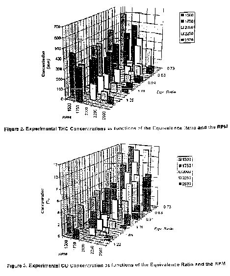


DETAILED DESCRIPTION AND MODES OF CARRYING OUT THE INVENTION
The present invention provides a method for reducing carbon deposited in a combustion engine from the burning of hydrocarbon fuel. The method comprises the steps of forming a fuel-water based additive mixture by adding a sufficient amount of a water-based additive to a fuel to form the fuel-water based additive mixture. The fuel-water based additive mixture is introduced to the engine during engine operation such that carbon deposited on the engine from combustion of the fuel-water based additive mixture is less than carbon deposited from the combustion of the fuel without the additive.
The invention, in another aspect, provides a fuel-water based additive mixture which comprises a fuel and the water based additive.
As set forth in the detailed example below, which is offered by way of illustration and is not intended to limit the invention in any manner, the method and mixture of the invention reduced carbon buildup in an engine. As a result, the invention also provides methods for achieving use of lower octane fuel, avoidance of problems associated with pre-ignition caused by carbon buildup inside the cylinders, reduction in fuel costs of an engine by allowing use of lower octane fuel, improvement in performance of an engine by the reduction in carbon erosion of valve seats and other control surfaces, and reduction in emissions caused by such carbon erosion which allows incomplete combustion products to escape into the exhaust thus raising emissions, and maintenance of higher combustion efficiency for a longer period of the life of the engine thus saving fuel and reducing maintenance costs. These other methods provided by the invention are achieved by the steps of forming a fuel-water additive mixture, and introducing said mixture to said engine during said engine operation such that carbon deposited on the engine from combustion of said mixture is less than carbon deposited from the combustion of the fuel in the absence of the additive.
Water-Based Additive
In the present invention, the water-based additive comprises a small amount of crystalline structured water with crystals, referred to herein as 1E crystals, in the micron or submicron size range. Growth and formation of these 1F crystalline water structures and preparation of the water-based additive are described below. Pending U.S. Patent
Applications 08/558,330 and 08/799,645, which are incorporated by reference, also disclose 1B crystalline water structures, solutions thereof, methods for making the 1F crystals, and methods for making concentrated solutions of the 1E water crystals. The type of microscopic crystalline structure, referred to therein is also referred to herein as IE crystal structured water.
Accordingly, the water-based additive of the present invention is an IE crystal based additive.
1E crystal structured water is a structured liquid in which the k crystal structures are induced in the liquid by strong electric fields from the electric field of an ion or from the dipole moment of molecules. While structured liquids can be formed from a variety of polar solvents, IE-structured water is a specific case of the general class of structured liquids that is formed from water molecules.
By way of explanation, not limitation, the formation of k structured water is illustrated as follows: When salt (e.g. NaCl) is dissolved in water, the sodium and the chlorine become ions in the water because of the strong dipole moment of water molecules.
Very dilute solutions are considered in which positively or negatively charged ions attract water molecules which have electric dipole moments. However, under these very dilute conditions, one finds that the water molecules surrounding an ion turn into a form of ice, not the ordinary ice where the unit cell has translational invariance, but one in which the crystalline structure of water surrounding the ion has a special symmetry due to the spherical nature of the coulombic force between the ion and the water molecule. The spherical symmetric icy structure surrounding ions is called 1E structure indicating it is an icy structure formed under the effect of an electric field. The 1E structures were observed and recorded under electron microscopy, as disclosed in U.S. Patent Application 08/799,645, and as disclosed in Lo, Shui-Yin (1996) "Anomalous State of Ice," Modern Physics Letters B, 10:909-919; and (1996) "Physical Properties of Water with 1E Structures," Modern Physics
Letters B, 10:921-930.
Preparation of the Water-based additive
Generating more 1E structures and preparation of the water-based additive of the present invention, are described in U.S. Patent Applications 08/799,645 and 08/558,330, and involves forming concentrated crystal solutions of 1E structures. The method involves forming a first structured liquid comprising the 1E structures and/or fragments of IE structures.
This structured liquid comprises a liquid having a dielectric constant greater than 1 and a material having an uneven distribution in charge on the surface of the material. An example of such material is NaCl. The first structured liquid is sufficiently diluted by repetitive dilution to form a second structured liquid. From the second structured liquid, the 1E structures are concentrated to form a concentrated crystal solution.
Methods for concentrating 1E solutions are disclosed in a patent application, incorporated herein, which was filed in the United States Patent and Trademark Office by the inventor of the present invention on July 10, 1997 but for which applicant has not yet received notice of a serial number assigned by the USPTO. The disclosed methods include reverse osmosis, doping a solution with beads that release an k nucleating material, gas chromatography, fractional distillation, use of an electrical wire dipole, and dynamic freezing.
For example, a concentrated 1E solution has been achieved using a reverse osmosis membrane. The exact size and type of filter depended on the dipole liquid selected to start with in creating the crystal structure solution. As a result, the reverse osmosis membrane pore size selection and concentration of the structured liquid is achieved according to the physical size of the crystal structures involved. To be specific, a quantity of a dilute or weak IE crystal structure solution is passed through a reverse osmosis unit which contains a membrane with a pore size of about 1.8 nanometers. This size filter is small enough and intended to allow only the passage of single molecules of water at one time through the pore.
The reverse osmosis unit is typical of those commercially available in various sizes and flow capacities and consists of an outside housing, a membrane and sealed end caps with holes for tubing to be connected. A carbonator type vane pump with an electric motor is attached by tubing to the reverse osmosis unit inlet side and when the motor is turned on, the pump maintains a pressure on the membrane by means of the tubing, kept in the range of 100-200 psi by adjusting a valve on the outlet side of the reverse osmosis unit. A key strategy for varying the concentration of the very dilute 1B crystal solution is the use of the reverse osmosis machine in reverse from its intended method by disposing of the output water and recycling the water that will not pass through the filter pore size selected. It has been determined that the selection of pore size will be dependent on the size of the molecule of the liquid utilized. For water, the membrane pore size selected was just slightly smaller than the size ofthe water molecule, about 1.8 nanometers, but it can vary from 1.0 nanometers to 3.0 nanometers or more depending on the liquid/material system selected. Figure 6 illustrates a reverse osmosis system 10 for concentrating crystal structured water. The weak solution 102 is added to tank 100 then said weak solution is drawn up through pipe 108 by means of pump 118 then pressurized into tube 112 which goes through pressure gage 116 and on through tube 114 into the entry side ofthe reverse osmosis unit 120. The weak solution then flows through the membrane assembly 122 wherein the single water molecules are driven through said membrane 122 by the pressure created by pump 118 acting against valve 126 and exit through port 128 and are collected through tube 130 into tank 104 as a weaker solution 106.
The crystal structure water, being composed of groups of water molecules, does not go through the membrane 122 and so it flows out of the reverse osmosis unit 120 through port 124. The now more concentrated crystal structure water then flows through adjustable valve 126 which is adjusted to create the membrane back pressure as shown at the valve 116. The crystal structure water then returns through tube 110 to the original tank 100 where it mixes with the weak solution 102 remaining in tank 100. By constant recirculation around the system described above, the single water molecules are continuously removed from the weak solution and are stored in tank 104 causing the mixture in tank 100 to become a stronger concentration of crystal structure water solution. As a result, one can stop the procedure as the desired concentration level desired.
The water-based additive of the invention used in the example disclosed herein was prepared by a doping method. In this method, water was used as a dipole liquid.
0.05 moles of platinum chloride was mixed with 100 ml of pure 18 Meg source water, which is a highly pure water. Removal of impurities from the dipole liquid was extremely important. The resulting mixture was called DO. DO was then serially diluted to produce progressively more dilute solutions which were designated, respectively, D1 through D9. For example, D1 was produced by mixing 10 ml of DO with 90 ml of pure 18 Meg source water.
Then D2, D3, D4 and so on up to D9 were produced in the same manner as D1, that is by adding 10 ml of each dilution to 90 ml of 18 Meg pure source water. Equal volumes of D9 solution and PVC beads (i.e. 50% v/v) were mixed. The PVC beads were 65 durometer, food grade PVC pellets. The D9-PVC solution was allowed to stand for about two hours, at which time the UV absorbance (wavelength 195 nm) of the solution was, in the various solutions prepared by this method, from about 0.5 to about 2.0. In order to concentrate the 1B structures, this solution was then processed through a reverse osmosis filter and the volume reduced to 1/10th to 1/40th of the original volume. This reduced volume had a UV absorbance at 195 nm of about 1.5 to about 3.0 in the various reduced volume solutions prepared by this method. By examination of electron micrographs of 1E solutions prepared for electron microscopy, it was estimated that the percent by weight of k structures in this dipole liquid (i.e. water) was from about 2% to about 10% ofthe weight of the water. This 1E structured liquid is considered the water-based additive of the invention. As used herein, a percent k solution means (100)weight of k structures/[weight of H2O + weight of k structures] in a given volume.
As used in the example below, the water based additive had a UV absorbance at 195 nm of 2.5. The water-based additive was mixed with 95% 2-propanol in a ratio of one part water-based additive to 20 parts 2-propanol, a ratio of 1:20. The water-based additiveisopropanol mixture was mixed with the fuel in a ratio of two parts of water-based additiveisopropanol mixture to 98 parts fuel, such that the water based additive (IE structured liquid) was 0.1% or 1000ppm in the fuel, forming a fuel-water based additive mixture.
For use in the present invention, the concentration of 1E structures in the waterbased additive (i.e. the percentage 1E solution) can vary from about 0.2 % to about 20 %. A preferred range of concentrations is from about 0.5% to about 10%.
As set forth in the Example below, the water based additive of the invention was first mixed in a 1:20 ratio with 95% 2-propanol. The water based additive-isopropanol mix was added to the fuel to form a 0.1% (v/v) fuel-water additive mixture, i.e 1000 ppm..
At the 0.1% (v/v) loading, the fuel-water additive mixture reduced carbon deposited when the mixture was introduced to the engine and underwent combustion. The loading levels of water-based additive to fuel that find use in the invention range from about 0.02% (v/v) to about 5.0% (v/v), a preferred range being from about 0.03% (v/v) to about 3.0% (v/v).
The hydrocarbon fuel which comprised the fuel-water based additive of the invention was 87 RON (research octane number) Chevron regular gasoline that was commercially available. The hydrocarbon fuels which finds utility in the invention include, but are not restricted to, the group consisting of gasoline, diesel fuel, methane, propane, heating oils, bunker oils, naptha, and methanol, which hydrocarbon fuels are used in internal combustion engines, including spark-ignited engines, diesel engines, gas turbines, and in boilers and heaters.
EXAMPLE
Two sets of studies were performed to determine the effects of the 1E fuel additive on carbon deposition and on engine out emissions. In both studies, the following conditions were used. Referring to Figure 1, studies were done using a single cylinder sparkignited Mark 111 Transparent Combustion Engine (Megatech Corp., Billerica, MA) without an exhaust emission control catalyst. Engine specifications are given in Table 1.
Table 1 - Experimental Engine Specifications
Bore 1 5/8"
Stroke 2"
Compression Ratio 3:1
Operating Speed 400-4000 RPM
Power Approximately V2 HP
Cooling System Forced Air
Fuel Injection System Carburetor injection
Lubricant Oil-less
The dynamometer was used to start and load the engine. It was also possible to monitor engine speed, torque, cylinder pressure, manifold pressure, cooling air pressure, and power output of the engine by the dynamometer. The cylinder or combustion chamber in the engine is made of a special heat resistant glass. This enabled one to monitor carbon deposition during engine operation.
High accuracy rotometers were used to measure both the flow rates of fuel and air. An electronic fuel pump and surge-tank were used to establish reliable fuel and air delivery, respectively. The engine system had two carburetor controls. A needle valve controlled the amount of fuel that flowed through the lines, and a throttle valve controlled the amount of air in the airfuel mixture to establish the equivalence ratio(4), defined as the actual airfuel ratio to the stoichiometric airfuel ratio). A commercially available gasoline with 87 RON was used as the fuel. In order to avoid fuel composition changes, the same batch of gasoline was used for all of the studies described herein.
The water-based fuel additive used an 1E crystal solution having a concentration of about 2% IE. crystals. The water based additive was prepared as described above. A fuel-water based additive mixture was formed by adding a water-based additive (which, as described above, is a 1:20 mixture of the 1E solution and 2-propanol)to the fuel and homogeneously dispersing it into the fuel. At the 0.1% (v/v) loading (i.e. the final volume of the 1F crystal solution in the fuel was 0.1% v/v or 1000 ppm) used in the studies, no clouding was observed initially and over an extended period of time, and the gasoline-water based additive mixture was clear. The fuel-water based additive mixture was introduced to the engine during engine operation.
Engine-out emissions for NOx, total hydrocarbons (THC) and CO were measured by an on-line digital gas analyzer (OTC RG240 Digital Gas Analyzer, Owatonna, MN) connected to the exhaust pipe by a sample line.
Carbon deposits in the engine were measured gravimetrically as follows. The engine was operated under sufficiently fuel-rich conditions that led to measurable amounts of carbon deposits on the piston head in a 30-minute run. After each experiment in which either fuel without water-based additive or the fuel-water based additive mixture was introduced to the engine during engine operation, the engine was completely dismantled, and the carbon deposited on the piston head was carefully scraped off, and weighed using a sensitive analytical balance. The engine was then reassembled to undertake the next study.
In the first set of studies, procedures were carried out in the absence of the water based additive to establish the baseline conditions. In the second set of studies, identical procedures were performed in the presence of the water based additive that was homogeneously dispersed into the gasoline at 0.1% (v/v) to form a fuel-water based additive mixture.
Engine exhaust emissions were determined as a function of engine speed at 1500, 1750, 2250, and 2500 rpm and at different equivalence ratios, both for the base case and in the presence of the fuel- additive mixture.
Engine exhaust emissions are presented in Figures 2, 3 and 4 for the baseline conditions. These results showed that CO and NOX were strongly dependent on the equivalence ratio while THC was not. As seen in Figure 2, THC emissions showed a slight minimum around = 0.96-1.0 depending on the engine speed. In addition, an increase in engine RPM decreased THC emissions. Minimum THC emissions was obtained at 2500 RPM. As seen in Figure 3, CO concentration uniformly increased with decreasing equivalence ratio as expected at a constant RPM. The production of some CO is inevitable when fuel is burned with insufficient air. However, some CO will be emitted under a broad range of conditions because of the mixing and reaction rate limitations.
The importance of NOX emissions from combustion sources lies in its contribution to the formation of secondary atmospheric pollutants. As seen in Figure 4, NOX emissions increased with increasing equivalence ratio within the range investigated as expected from flame temperature considerations. For engine speeds of 2000, 2250, and 2500 RPM, NOX concentration showed maxima around equivalence ratio of 1.05, as expected (Bosch Automotive Handbook, 3rd ed. p. 478-9, Robt. Bosch GmBh). Since the combination of temperature and fuel and oxygen concentration determines the amount of NOX formation, an NOX emissions peak occurred on the fuel lean side ( (1.0). Minimum NOX emissions were observed at engine speed of 2250 RPM.
In the second set of experiments, i.e. in the presence of the fuel-water based additive mixture, the engine exhaust emissions showed no systematic departure from the trends observed in the absence of the water based additive. In addition, the levels of NOX, THC, and CO were well within the limits of accuracy of the measurements made in the absence of water based additives.
Carbon formation studies were performed under sufficiently fuel-rich conditions in which measurable carbon deposition on the piston head occurred over a 30minute period. In this study, carbon deposition rates occurred at an equivalence ratio of 0.72 (fuel rich). Lower equivalence ratios led to excessive carbon formation and resulted in the early termination of runs. At higher equivalence ratios, carbon formation rate was too slow, and longer operating times became necessary to accumulate measurable quantities of deposits.
In Figure 5, the amount of carbon deposited on the piston head was plotted as a function of engine speed at the airfuel equivalence ratio of 0.72 and at the end of a 30minute operating time, both for the base case and in the presence of the additive. The experiments corresponding to each data point were repeated three times to assess the repeatability of the results. Average standard deviations for the base case and in the presence of additive were 0.16 and 0.11, respectively.
As seen in Figure 5, carbon deposition rates decreased with increasing RPM.
Decrease in residence time in the engine at high RPM is a possible explanation for this finding. However, it is particularly important to note that the presence of 0.1% (v/v) water based additive in the fuel significantly decreased the rate of carbon deposition at a given
RPM. In addition, this effect was observed consistently over the entire engine speed range investigated. As can be seen in Figure 5, carbon deposition rate decreased by as much as 32%, 20%, 44% at 1750, 2000, and 2250 RPM, respectively.
These results demonstrated that the method, water-based additive, and fuelwater based additive mixture of the invention decreased carbon deposition rate on the piston head of an internal combustion engine by as much as 44% compared with the use of the fuel in the absence of the water based additive.
Accordingly, the steps of the invention which involved forming the fuel-water based additive mixture and introducing the mixture to the engine during engine operation comprise the following methods which the invention also provides: method for using lower octane fuel; method for increasing efficiency of engine performance by reducing the rate of pre-ignition caused by carbon build-up in the cylinders); method for reducing fuel costs of an engine by allowing use of lower octane fuel; method for increasing engine performance by reducing carbon erosion of valve seats and other control surfaces; method for reducing emissions caused by such carbon erosion which allows incomplete combustion products to escape into the exhaust thus raising emissions; method for maintaining combustion efficiency for a longer period of the life of the engine thus saving fuel and reducing maintenance costs.
WATER
BASED ADDITIVE FOR SUPPRESSION OF COKE FORMATION
WO9928412
WO9928412
A method for reducing coke formation from pyrolysis of hydrocarbon reactant in a reactor, comprises the steps of forming a hydrocarbon reactant-water-based additive mixture, and introducing the mixture to the reactor. The coke deposited in the reactor from pyrolysis of the hydrocarbon reactant-waterbased additive mixture is less than coke desposited from pyrolysis of hydrocarbon reactant in the absence of the water based additive. Also provided is a hydrocarbon reactant-water-based additive mixture, the water based additive comprising a IE crystal structured liquid.
1. Field of the Invention
The invention relates to a method of reducing coke formation from pyrolysis of hydrocarbon by adding a water based additive to hydrocarbon reactants. The invention further relates to a hydrocarbon reactant-water based additive mixture.
BACKGROUND OF THE INVENTION
2. Description of Related Art
The publications and other reference materials referred to herein to describe the background of the invention and to provide additional detail regarding its practice are hereby incorporated by reference. The most important olefins and diolefins used to manufacture petrochemicals are ethylene, propylene, butylenes, and butadiene (Matar, S. and Hatch, L.F., "Chemistry of Petrochemical Processes," Gulf Publishing Co., Texas (1994)), Ethylene is one of the most important building blocks of synthetic organic chemistry. It is used in the manufacture of polyethylene and other products. Ethylene production rate has steadily increased over the years from 29 million pounds in 1985 to 46.7 million pounds in 1995 (Chem. Engin. News, June 24, 1996). The majority ofthe ethylene produced today is based on the steam cracking or pyrolysis of alkanes, such as ethane, propane and butane, as well as heavier feedstocks such as aphtha and gas oil (Lee, L.K.K., et al., Oil and Gas J. Sept. 10, 1990, p. 60).
The steam cracking of a feedstock is accomplished in the coils of a pyrolysis furnace followed by quenching of the gas in a heat exchanger (Matar, S. and Hatch, L.F., ibid) or the transfer line exchanger (TLE). A technologically important by-product of steam cracking is coke formation. Because of its accumulative nature, coke deposits build up on reactor walls and influence reactor performance in a number of ways. First, due to coke, the surface temperature of the coils is increased. This adversely affects, i.e. reduces the service life of the coil, and makes it impossible to obtain normal pyrolysis temperatures in the reactor. Second pressure drop is increased due to the reduction of the inner diameter of the coil upon coking which reduces flow rates through the coil, and causes a reduction in heat exchange efficiency. Third, coking may lead to corrosion of the coil due to carbonization.
Consequently, decoking of the reactor coils has to be carried out periodically, which results in loss of production and increased maintenance costs. In ethane cracking, commercial reactors must be decoked typically every 20-60 days (Sundaram, K.M. et al. (1981) AICHE Journal 7:946).
Sundaram (ibid) studied the thermal cracking of ethane in a nitrogen matrix in the temperature range 750 -870 C in a mixed reactor. Major products reported were ethylene, methane, C4H and C5+. They found the gas phase decomposition to be first order in ethane concentration with an apparent activation energy of 54.0 kcal/mol in agreement with previous studies in a tubular pilot reactor (Froment, G.F. et al. (1976) Ind. Eng. Che. process Design Develop., 15:495). Similar results were reported more recently by Fro (Rev. Chem. Eng. (1990) 6:293) for the steam cracking of ethane. Coke was deposited on an Inconel 500 coupon suspended inside the reactor from the arm of an electrobalance. The rate of formation of coke was found to be time dependent, starting initially at a faster rate and reaching an asymptotic value later in the run. The initial coke formation rate was attributed to catalytic wall effects. Once the coke layer is deposited on the coupon, the rate reaches its asymptotic value corresponding to coke deposition on coke. The estimated activation energy for coke formation base on a kinetic analysis of a reaction model was in the range of 28.349.9 kcal/mole. Gas composition measurements also indicated the rapid formation rate of CO early in the experiments, which leveled off to an asymptotic value following the coverage of the metal surface by coke. Initial CO production was proposed to be due to metal catalyzed oxidation of hydrocarbon moieties on reactor walls, and subsequent CO formation was attributed to the steam gasification of carbon. These studies also indicated that higher
steam dilutions decease coke formation rates.
The decomposition of propane in a nitrogen matrix was studied by Sundaram and Fro (1979) in a mixed reactor in the temperature range 720-870 C. Major products reported were ethylene, methane, andC3H6. The disappearance of propane was found to be first order in propane concentration with an activation energy of 49.04 kcal/mol. This is in agreement with the results of Van Damme et al. (AICHE Journal, 21:1065 (1975)) and Fro (1990) in the steam cracking of propane. The activation energy for coke formation was estimated to be 74.97 kcal/mole, again based on the kinetic analysis of a reaction model.
This is in agreement with the experimental results of Trimm et al. ("Fundamental Aspects of the Formation and Gasification of Coke" in Pyrolysis: Theory and Industrial Practice, L.F. Albright et al. Eds., Academic Press, NY, p. 203 (1983)) during the steam cracking of propane in a flow reactor.
Crynes and Crynes (Ind. Eng. Chem. Res. 26:2139 (1987)) also studied the formation of coke during the pyrolysis of alkanes on Incoloy 800 coupons in a flow reactor.
Temperature was maintained at 7000 C by mean of an electric furnace. They studied coking during the pyrolysis of ethane, ethane, ethene, propane, propene and isobutane. They found the following order for coking on the coupon: ethane ( ethene (propene (propane ( isobutane, with no coke deposition observed for methane at their experimental conditions. The effects of reactor surfaces on coke deposition rates during the pyrolysis of propane has been studied extensively by Renjun (Fundamental of Pyrolysis of Pyrolysis in Petrochemistry and Technology, CRC Pres, Boca Raton, USA (1993)) in an electrobalance reactor at 850 C. The order of increasing coke deposition rates was found to be nickel ) stainless ) quartz. High coking rates were also observed early on in the experiments, which later reached an asymptotic value upon surface coverage by coke.
At present three mechanisms have been proposed to account for coke formation in hydrocarbon pyrolysis in industrial and laboratory reactors: (1) Coke formation via metal-catalyzed reactions in which metal carbides have been proposed to be intermediates. The resulting coke is filamentous and contains 1-2 wt% metal; the metals are positioned primarily at the tips of the filaments. Filamentous coke has been produced at temperatures from about 400" C up to 10500 C (Albright, et al. (1988) Ind. Eng. Chem. Res. 27:755). This can be one of the coke formation mechanisms on metal reactor surfaces. (2)
Coke has also been proposed to form via polycyclic aromatic hydrocarbons (PAH) in the gas phase (see, for example, Wang, H. et al. (1994) J. Phys. Chem. 98:11465; and Gagurevich, I. Ph.D. Thesis, UCLA, 1997 for chemical paths in fuel-rich combustion), their nucleation and condensation into tar droplets followed by adsorption on surfaces where the tar proceeds to dehydrogenate into coke. This mechanism generally results in film or globular coke formation (Albright, L.F. et al. "Importance of Surface Reactions in Pyrolysis Units," in "Pyrolysis Theory and Industrial Practice, Albright, L.F. et al. Eds., Academic Press, NewYork, p. 233 (1983)). (3) Coke can also grow directly through the reactions of small gas phase species with sites on the coke surface. These species are likely to be acetylene or other olefins, butadiene, and free radicals such as methyl, ethyl, vinyl, phenyl or benzyl radicals.
This mechanism should be favored by higher temperatures and with higher concentrations of acetylene in the gas phase (see for example Mauss et al. 1994, for surface growth mechanisms of soot particles in combustion.)
The development of coke inhibitors have paralleled the various coke formation mechanisms described above. The techniques commonly used today to reduce coke formation include the pretreatment of feedstocks, changing the materials of construction of the reactor, altering the surface chemistry of the reactor, or the addition of coke inhibitors to the feedstock (Renjun, Z. Fundamentals ofPyrolysis in Petrochemistry and Technology, CRC Press, Boca Raton, USA, 1993; and Burns, K.G. et al. (1991) Hydrocarbon Processing, p. 83). The development and use of additives appears to be the most effective and practical method. Coke inhibitors reported in the literature include salts of alkali metals or alkali-earth metals at ppm quantities which are believed to promote coke gasification by steam. In addition, the use of organic polysiloxane compounds in ppm quantities have been shown to reduce the adhesion of coke to the coil walls. Sulfur compounds have also been used widely to suppress coke formation, especially early on in the pyrolysis process by passivating metal. surfaces (Renjun, 1993). Compounds containing tin, antimony, copper, phosphorous, and chromium were also reported to have a beneficial effect in suppressing coke formation (Renjun, 1993).
SUMMARY OF THE INVENTION
The present invention provides a method for reducing coke formation from pyrolysis of hydrocarbon reactant in a reactor. The method comprises the steps of forming a hydrocarbon reactant-water-based additive mixture, and introducing the mixture to the reactor. The coke deposited in the reactor from pyrolysis of the hydrocarbon reactant-water based additive mixture is less than coke deposited from pyrolysis of hydrocarbon reactant in the absence of the water based additive. The water-based additive is a structured liquid comprising 1E crystal structured liquid.
The invention, in another aspect, provides a hydrocarbon reactant-water additive mixture which comprises a hydrocarbon reactant and a water-based additive.
It is an object of the present invention to reduce the rate of carbon buildup, i.e. coke buildup that occurs in pyrolysis of hydrocarbons. Another object of the invention is to increase the productive operating period between shutdowns for removal of carbon buildup on the equipment surfaces of an ethane or propane or other hydrocarbon cracking equipment or production plants. Another object of the invention is to extend the life of heat-exchanger surfaces and heat exchanger equipment by reducing the insulating effects of carbon buildup on these surfaces and reducing the surface chemical attack of these surfaces that occurs in the presence of carbon buildup layers. Another object of the invention is the reduction in carbon erosion that is caused by free hard carbon particles in a gas stream impinging on equipment components made from expensive high-temperature alloys and stainless steels. Another object of the invention is the reduction in operating and maintenance costs of a hydrocarbon steam cracking plant.
These and many other features and attendant advantages of the present invention will become better understood by reference to the following detailed description of the invention when taken in conjunction with the accompanying drawings.
FIGURES
Figure 1 shows the reactor apparatus used to study the formation of coke during pyrolysis of hydrocarbon reactants.
Figure 2 shows representative data for steam pyrolysis of ethane.
Figure 3 shows coke formation in steam pyrolysis of ethane at 8300 C and 8450 C.
Figure 4 shows Arrhenius plots for the rate of formation of coke in the steam pyrolysis of ethane.
Figure 5 shows coke formation in the steam pyrolysis of propane at 8200 C and 8300 C.
Figure 6 shows Arrhenius plots for the rate of formation of coke in the steam pyrolysis of propane.
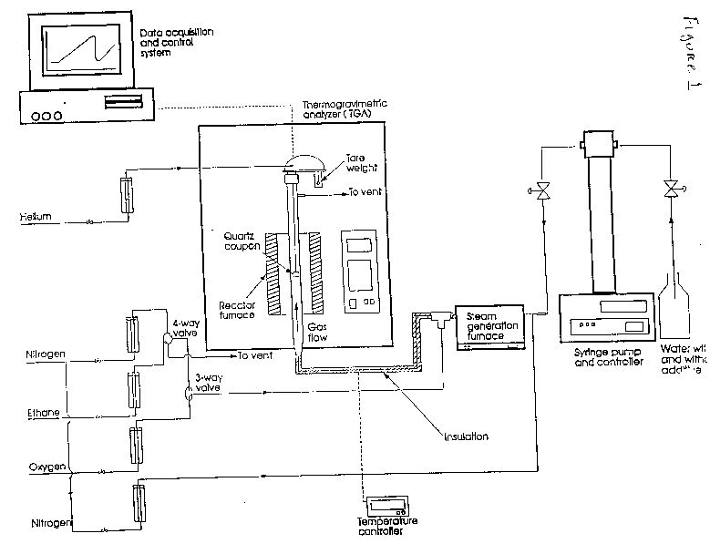


DETAILED DESCRIPTION AND MODES OF CARRYING OUT THE INVENTION
The present invention provides a method for reducing coke formation from pyrolysis of hydrocarbon reactant in a reactor. The method comprises the steps of forming a hydrocarbon reactant-water-based additive mixture, and introducing the mixture to the reactor. The coke deposited in the reactor from pyrolysis of the hydrocarbon reactant-water based additive mixture is less than coke deposited from pyrolysis of hydrocarbon reactant in the absence of the water based additive. The water-based additive is a structured liquid comprising 1E crystal structured liquid, as defined and disclosed below.
The invention, in another aspect, provides a hydrocarbon reactant-water additive mixture which comprises a hydrocarbon reactant and a water-based additive.
As set forth in the detailed example below, the method and mixture of the invention reduce the rate of carbon buildup, i.e. coke buildup that occurs in pyrolysis of hydrocarbons. As a result, the invention also provides a method to increase the productive operating period between shutdowns for removal of carbon buildup on the equipment surfaces of an ethane or propane or other hydrocarbon cracking equipment or production plants. Further aspects of the invention involve a method to extend the life of heat-exchanger surfaces and heat exchanger equipment by reducing the insulating effects of carbon buildup on these surfaces and reducing the surface chemical attack of these surfaces that occurs in the presence of carbon buildup layers. In still another aspect, the invention reduces carbon erosion that is caused by free hard carbon particles in a gas stream impinging on equipment components made from expensive high-temperature alloys and stainless steels. The invention also provides a method for reducing operating and maintenance costs of a hydrocarbon steam cracking plant. All of these methods are achieved by forming a hydrocarbon reactant-water based additive mixture and introducing the mixture to a reactor under conditions in which coke deposited in the reactor from pyrolysis of the hydrocarbon reactant-water based additive mixture is less than coke deposited from the pyrolysis of hydrocarbon reactant in the absence of the additive.
Water Based Additive
In the present invention, the water-based additive comprises a small amount of crystalline structured water with crystals, referred to herein as 1E crystals, in the micron or submicron size range. Growth and formation of these 1E crystalline water structures and preparation of the water-based additive are described below. Pending U.S. Patent
Applications 08/558,330 and 08/799,645, which are incorporated by reference, also disclose 1E crystalline water structures, solutions thereof, methods for making the 1E crystals, and methods for making concentrated solutions of the 1E water crystals. The type of microscopic crystalline structure, referred to herein is also referred to herein as 1E crystal structured water.
Accordingly, the water-based additive of the present invention is an 1E crystal based additive.
1E crystal structured water is a structured liquid in which the 1E crystal structures are induced in the liquid by strong electric fields from the electric field of an ion or from the dipole moment of molecules. While structured liquids can be formed from a variety of polar solvents, I,-structured water is a specific case of the general class of structured liquids that is formed from water molecules.
By way of explanation, not limitation, the formation of IE structured water is illustrated as follows: When salt (e.g. NaCl) is dissolved in water, the sodium and the chlorine become ions in the water because of the strong dipole moment of water molecules.
Very dilute solutions are considered in which positively or negatively charged ions attract water molecules which have electric dipole moments. However, under these very dilute conditions, one finds that the water molecules surrounding an ion turn into a form of ice, not the ordinary ice where the unit cell has translational invariance, but one in which the crystalline structure of water surrounding the ion has a special symmetry due to the spherical nature of the coulombic force between the ion and the water molecule. The spherical symmetric icy structure surrounding ions is called 1E structure indicating it is an icy structure formed under the effect of an electric field. The 1E structures were observed and recorded under transmission electron microscopy, as disclosed in U.S. Patent Application 08/799,645, and as disclosed in Lo, Shui-Yin (1996) "Anomalous State of Ice," Modern Physics Letters B, 10:909-919; and (1996) "Physical Properties of Water with 1E Structures," Modem Physics Letters B, 10:921-930.
Preparation of the Water-based additive
Generating more 1F structures and preparation of the water-based additive of the present invention, are described in U.S. Patent Applications 08/799,645 and 08/558,330, and involves forming concentrated crystal solutions of k structures. The method involves forming a first structured liquid comprising the 1E structures and/or fragments of 1E structures.
This structured liquid comprises a liquid having a dielectric constant greater than 1 and a material having an uneven distribution in charge on the surface of the material. An example of such material is NaCl. The first structured liquid is sufficiently diluted by repetitive dilution to form a second structured liquid. From the second structured liquid, the IE structures are concentrated to form a concentrated crystal solution.
Methods for concentrating 1E solutions are disclosed in a patent application, incorporated herein, which was filed in the United States Patent and Trademark Office by the inventor ofthe present invention on July 10, 1997 but for which applicant has not received notice of a serial number assigned by the USPTO. The disclosed methods include reverse osmosis, doping a solution with beads that release an 1F nucleating material, gas chromatography, fractional distillation, use of an electrical wire dipole, and dynamic freezing.
For example, a concentrated 1E solution has been achieved using a reverse osmosis membrane. The exact size and type of reverse osmosis membrane depended on the dipole liquid selected to start with in creating the crystal structure solution. As a result, the reverse osmosis membrane pore size selection and concentration of the structured liquid is achieved according to the physical size of the crystal structures involved. To be specific, a quantity of a dilute or weak 1E crystal structure solution is passed through a reverse osmosis unit which contains a membrane with a pore size of about 1.8 nanometers. This size filter is small enough and intended to allow only the passage of single molecules of water at one time through the pore. The reverse osmosis unit is typical of those commercially available in various sizes and flow capacities and consists of an outside housing, a membrane and sealed end caps with holes for tubing to be connected. A carbonator type vane pump with an electric motor is attached by tubing and valves to the reverse osmosis unit inlet side and when the motor is turned on, the pump maintains a pressure on the membrane by means of the tubing and valves, and is kept in the range of 100-200 psi by adjusting a valve on the outlet side of the reverse osmosis unit. The key strategy for varying the concentration of the very dilute 1E crystal solution is the use of the reverse osmosis machine in reverse from its intended method by disposing of the output (clean) water and recycling the water that will not pass through the filter pore size selected. It has been determined that the selection of pore size will be dependent on the size of the molecule of the liquid utilized. For water, the membrane pore size selected was just slightly smaller than the size of the water molecule, about 1.8 nanometers, but it can vary from 1.0 nanometers to 3.0 nanometers or more depending on the liquid/material system selected. Figure 6 illustrates a reverse osmosis system 10 for concentrating crystal structured water. The weak solution 102 is added to tank 100 then said weak solution is drawn up through pipe 108 by means of pump 118 then pressurized into tube 112 which goes through pressure gage 116 and on through tube 114 into the entry side ofthe reverse osmosis unit 120. The weak solution then flows through the membrane assembly 122 wherein the single water molecules are driven through said membrane 122 by the pressure created by pump 118 acting against valve 126 and exit through port 128 and are collected through tube 130 into tank 104 as a weaker solution 106.
The crystal structure water, being composed of groups of water molecules, does not go through the membrane 122 and so it flows out ofthe reverse osmosis unit 120 through port 124. The now more concentrated crystal structure water then flows through adjustable valve 126 which is adjusted to create the membrane back pressure as shown at the valve 116. The crystal structure water then returns through tube 110 to the original tank 100 where it mixes with the weak solution 102 remaining in tank 100. By constant recirculation around the system described above, the single water molecules are continuously removed from the weak solution and are stored in tank 104 causing the mixture in tank 100 to become a stronger concentration of crystal structure water solution. As a result, one can stop the procedure as the desired concentration level desired.
The water-based additive of the invention used in the detailed example disclosed below was prepared by a doping method. In this method, water was used as a dipole liquid. 0.05 moles of platinum chloride was mixed with 100 ml of pure 18 Meg source water, which is a highly pure water. Removal of impurities from the dipole liquid was extremely important. The resulting mixture was called DO. DO was then serially diluted to produce progressively more dilute solutions which were designated, respectively, D1 through D9. For example, D1 was produced by mixing 10 ml of DO with 90 ml of pure 18 Meg source water. Then D2, D3, D4 and so on up to D9 were produced in the same manner as D1, that is by adding 10 ml of each dilution to 90 ml of 18 Meg pure source water. Equal volumes of D9 solution and PVC beads (i.e. 50% v/v) were mixed. The PVC beads were 65 durometer, food grade PVC pellets. The D9-PVC solution was allowed to stand for about two hours, at which time the UV absorbance (wavelength 195 nm) of the solution was, in the various solutions prepared by this method, from about 0.5 to about 2.0. In order to concentrate the 1E structures, this solution was then processed through a reverse osmosis filter and the volume reduced to l/lOth to 1/40th ofthe original volume. This reduced volume had a UV absorbance at 195 nm of about 1.5 to about 3.0 in the various reduced volume solutions prepared by this method. By examination of transmission electron micrographs of IE solutions prepared for electron microscopy, it was estimated that the percent by weight of 1E structures in this dipole liquid (i.e. water) was from about 2% to about 10% of the weight of the water. This 1E structured liquid is considered the water-based additive of the invention.
As used herein, a percent 1E solution means (100)weight of 1E structures/(weight of H2O + weight of k structures ) in a given volume. As used in the example below, the water based additive had a UV absorbance at 195 nm of 2.5. For use in the present invention, the concentration of 1E structures in the water-based additive (i.e. the percentage 1E solution) can vary from about 0.2 % to about 20 %. A preferred range of concentrations is from about 0.5% to about 10%.
In the industrial cracking of ethane to produce ethylene, hot steam is mixed with the gas ethane in a suitable chamber held at the desired temperature and pressure. The cracking process produces free carbon as an unwanted byproduct, which necessitates the shutdown of equipment for periodic maintenance to remove the buildup. In the method of the invention, 1E structured water replaced the water used to produce the steam used in cracking and the resulting reduction of coke formation upon pyrolysis of hydrocarbon reactant-water based additive mixture is one of the applications of the present invention.
A test was carried out, as described below, to determine the effect of the water based additive on the pyrolysis of hydrocarbons, in particular, ethane as occurs in the steam cracking of ethane. In the normal cracking process the chemical reaction is expressed as:
2C2H6 + H2O + O2 = 2C2H4 + 2H2O (ethane) (ethylene)
The actual reaction is never 100% complete and partial products of the reaction process are produced such as free carbon, which then deposits in layers, on the walls of the reactor.
In the case of the use of IE structured water for the production of steam, the reaction is enhanced by the presence of the 1E structures which act as catalysts, as shown by the following equation.
2C2H6 + H2O(IE) + O2 = 2C2H4 + 2H2O (ethane) (ethylene)
The test was done under controlled laboratory conditions and a diagram of the test apparatus is attached in Figure 1. The test equipment consisted of a quartz reactor which was maintained at 8500C by a furnace. A steam generator was used to heat incoming deionized water to steam. Nitrogen was also mixed with the steam. A second chamber was used to mix the steam, nitrogen and ethane gas to a desired temperature and pressure. The mixture was then fed into the quartz reactor and heated to the 850"C test temperature.
Free carbon formed during the cracking process deposits on the surface of a quartz coupon. The coupon was supported in a thermogravimetric analyzer, which measured the change in weight that occurred as the carbon built up on the coupon. The test setup had the following parameters:
Temperature: 830C
Methane 1.8 cc/sec
Stream = 5.6 cc/sec
Qnitrogen 2.6 cc/sec
Coupon Size: 2x2x0.1 cm
The test parameters chosen were typical of those used in industrial ethane and propane cracking plants. It should be understood that the rate at which steam is introduced in relation to the flow rates hydrocarbon reactants can, and the method of the invention is not limited to the rate disclosed herein.
After a specified test time, the ethane or propane was turned off and the system was purged with oxygen. The oxygen quickly oxidized the carbon deposit on the coupon to carbon dioxide which exited the quartz reactor and the weight of the coupon reduced. The rate of deposition of the carbon on the coupon was readily measured over time.
The system was then purged with nitrogen to remove any traces of oxygen and the test was repeated.
In the second test which was the 1E structured water test, a sample of 1E structured water was used to replace the deionized water used in the first test and the test was then repeated. In this second test, the rate of carbon deposition was again recorded by thermogravimetric analyzer and it was found to be less than that of the deionized water only.
The test was done with ethane and with propane as the main gas.
In the tests on ethane, the carbon buildup rate using deionized water as the steam source was 0.341 pg/cm2-sec at 830"C. The carbon buildup rate for then, structured water as the steam source, was 0.089 ,ug/cm2-sec. This was a reduction of 74%, a very significant amount.
In the case of propane cracking, the carbon buildup rate using deionized water as the steam source was 0.443 ug/cm2-sec at 8200C. The carbon buildup rate at 8200C for the 1E structured water as the steam source, was 0.193 ,ug/cm2-sec. This was a reduction of 56%, also a very significant amount. The carbon buildup values at 8300C fore the propane were 0.514 and 0.331 Zg/cm2-sec, a reduction of 36% which was also very significant.
EXAMPLE
Effect of Water Based Additive on Rate of Formation of Coke Deposit in Steam Cracking of Ethane and Profane
In Figure 1, the experimental apparatus used to study the formation of coke during the pyrolysis of hydrocarbons, and in particular, during the steam cracking of ethane and propane is illustrated. This apparatus is a modified version of the set up used to study coke formation in the pyrolysis and oxidative pyrolysis of methane and methyl chloride (Tran, T. et al. (1994) Ind. Eng. Chem. Res., 33:32). The main component ofthe experimental system is a Cahn 131 thermogravimetric analyzer (TGA, Madison, WI) that has a detection sensitivity of 1 microgram. The system has an electronic microbalance which continuously measures and records the mass loss or gain of a substrate material or coupon which was suspended from the balance by means of a 0.0127 cm diameter platinum hangdown wire.
Furnace temperature profile and coupon mass data were acquired and stored by the data acquisition and control system. The data acquisition hardware consisted of an IBM compatible PC and software provided by Cahn Systems. The software allowed for the operation of the furnace for any temperature time history. The coupon material used for these studies was quartz, with dimensions 2 cm wide x 2 cm long x 0.1 cm thick. The coupon was centrally located inside a 3.5 cm i.d. x 32.5 cm long quartz reactor that was vertically placed inside a single zone furnace.
The heating elements inside the furnace spanned a distance of about 15 cm, which thereby allowed the establishment of nearly isothermal central zone of about 2 cm in length in which the quartz coupon was placed (Tran, ibid).
Either deionized water or the water based additive, which comprised 1E crystals (Lo, S. (1996)"Anomalous State of Ice," Modern Physics Letters B, 10: 909; Lo, S.
(1996) "Physical Properties of Water with IE Structures," Modern Physics Letters B 10:921) was pumped using a high precision metering syringe pump (ISCO-2600 with series D
Controller, Lincoln, NE) and was vaporized in an electric furnace maintained at 4000 C.
Nitrogen gas was introduced into the liquid at the upstream of the steam furnace as a gas carrier. The hydrocarbon reactants, either ethane or propane gases, and some additional nitrogen carrier gas were then mixed with the steam to form a hydrocarbon reactant-steam mixture (i.e. absence of water-based IE additive) or a hydrocarbon reactant-water based additive mixture.
The water based additive of the invention replaced the water used as a source for steam. As steam, the water based additive was added to the ethane or propane to form a hydrocarbon reactant-water based additive mixture. Hydrocarbon reactant-water based additive reduced coke deposited in the reactor. The relative levels or flow rates of hydrocarbon reactant and steam for forming hydrocarbon reactant-water based additive mixture that find use in the invention range were: Qernane = 1.8 cc/sec, Stream = 5.6 cc/sec, Nitrogen = 2.6 cc/sec. It should be understood that in the step of forming the hydrocarbon reactant-water based additive mixture that the rate at which steam is introduced in relation to the flow rates hydrocarbon reactants can vary, and that the method of the invention is not limited to the rate disclosed herein.
The hydrocarbon reactant-water based additive mixture was then introduced to the reactor through electrically heated lines. All the gas flows were regulated by high accuracy rotameter (Mathes on, Cucamonga, CA) that were calibrated before the experiments. The weighing components of the TGA were protected from the reaction products by passing helium purge gas through the chamber. The gases used were obtained from Mathes on (Cucamonga, CA) unless otherwise indicated and had the following purities:
He:99.99%; C2H:99.9%; C3H8:99.99%; N2:99.999%, and 02:99.9% (Liquid Air Co.).
All the studies were conducted at 1 atm pressure and for 1 hour reaction time.
Before each run, the reactor was purged with N2 for about 10 minutes and then decoked using 15% O2 (balance N2) mixture to assure that the reactor and the coupon were coke free.
This was accomplished both by visually observing the appearance of the coupon through an observation hole in the furnace and by monitoring the weight of the coupon during the decoking process. If the appearance of the coupon was transparent and nonluminous, and its weight did not decrease with time and retained its original (coke-free) value, the coupon was assumed to be coke free. The reactor was then purged again with N2 for about 10 minutes after which a mixture was formed between the hydrocarbon reactants and steam (either deionized water or water-based additive), and the mixture was introduced to the reactor. The primary reason for nitrogen purge before and after the decoking studies was to minimize the accumulation of potentially explosive mixtures in the reactor. Each run was repeated at least five times to ensure reproducibility and to assess the range of experimental errors associated with the experiments.
Results
Since the TGA had a sensitivity limit in the microgram level, it was necessary to determine the optimum gas flow rates that did not result in excessive noise, yet allowed the acquisition of reliable coking data over the range of concentrations and temperatures which were used during the experiments.
Following the initial scoping studies, a total gas flow rate of about 2.5 cm3/s, measured at STP, was determined suitable. Higher flow rates resulted in the establishment of undesirable flow patterns in the reactor that caused lateral movement of the hangdown wire and resulted in its contact with the baffle inside the reactor. It should be noted that at 2.5 cm3/s, the flow regime in the reactor would have been laminar and would have corresponded to a nominal residence time of 15 s and about 1.5 s to cross the quartz coupon. This residence time was determined by taking into account the volume occupied by the baffle (Tran, T., (1992) MS Thesis, UCLA Chemical Engineering). Overall reactant conversions, measured separately by gas chromatography at the exit of the reactor were generally in the range 2-5%. However, because the quartz coupon occupied a small fraction of the reactor volume, it was subjected to a nearly constant gas composition along the flow direction due to the differential conversion of the reactants within the 1.5 s reaction time. Consequently, one would have expected uniform coke formation along the coupon if diffusion limitations were also absent. If diffusion limitation were present, the variation of the boundary layer thickeness along the coupon would have led to non-uniform coke depostion. Coke formation appeared to be uniform along the coupon as determined by SEM in previous studies (Tran and Senkan, 1994), indicative ofthe absence of transport limitations under the study conditions investigated.
In Figure 2, a representative set of raw data obtained by the TGA is shown for the steam pyrolysis of ethane. As seen from this figure, the reproducibility of the experiments was excellent, well within 15% from one set to another. A close inspection of the individual experiments showed that cooking rates, i.e. the slope of the weight vs. time lines, were generally initially higher, but leveled off to an approximately constant value. The latter rate, corrected for the baseline shift due to the loss or gain of coke on the hang-down wire after the decoking process, was designated as the specific coke formation rate, RTGA in micrograms/min units. High initial coking rates were consistent with the results of other investigators (Sundaram, K.M. et al. (1979) Chem. Eng. Sci. 34:635; Renjun, Z. (1993)
Fundamentals of Pyrolysis in Petrochemistry and Technology," CRC Press, Boca Raton, USA; Froment, G.F. (1990) Rev. Chem. Eng. 6:293; Tran, T. et al. (1994) Ind. Eng. Chem. Res. 33:32).
The physical meaning of the weight change measured by the TGA was considered. As evident from the experimental system described above, the TGA simply measured the weight change experienced by the quartz coupon. This weight change could have been affected directly by molecular events, e.g. chemical reactions that resulted in the growth and/or destruction of molecular entities on the surface, or by macroscopic events, such as soot, tar particle collisions with the quartz coupon. Clearly, TA measurements could not distinguish between these two types of mechanisms. Consequently, these lumped sets of events, as detected by TGA, are referred to herein as the coke formation process.
The specific coke formation rate, rc, Fg/cm2-min) was then determined from the following equation:
rc=RVA (1) where A is the surface area of the coupon. The specific coke formation rate can also be represented by the following phenomenological expression:
rc=kOexp(-E/RT)f()C) Fg/cm2-min (2) where k0 is the specific rate constant for coke formation, E is the apparent activation energy, and f(C) is a functional dependency of coke formation on the composition of the gas phase.
This type of a rate expression has often been used to model coke formation kinetics (see for example Sundaram, K.M. et al. (1979) Chem. Eng. Sci. 34:635; Renjun, Z. et al. (1987) Ind. Eng. Chem. Res. 26:2528; Froment, G.F. (1990) Rev. Chem. Eng. 6:293; Tran, T. et al. (1993) Ind. Eng. Chem. Res. 33:32). As evident from the above expression, under differential conversions that should be observed along the 1 cm long quartz coupon, f(C) would be nearly constant. The determination of f(C) was not the subject of this study.
In Table I, the experimental conditions were investigated and summarized. As evident from this table, coke formation rates were determined not only at fixed C2 H6, C3H8 and H2O concentrations but over a range of temperature ranges both in the absence and presence of the 1E additive. It should be noted that the temperature ranges studied were different for different mixtures because of differences in the decomposition temperatures of C2H6 and C3H8. Consequently, all the experiments conducted did not correspond to identical residence times because of differences in gas velocities caused by different temperatures. In addition, changes in number of moles caused by the reaction process would have also altered residence times. These issues, however, should have had a relatively small effect on the results provided here. For example, differences in reactor temperatures should have introduced a variation in residence times no larger than about 2.3% between the lowest and highest temperature experiments, i.e. 100 x (840-820)/(820+273) = 2.3%. This uncertainty was well below the measurement errors associated with these types of experiments.
Similarly, percent change in the total number of moles would have been extremely small due to small conversions involved and the presence of steam and nitrogen dilution.
Table I. Operating Conditions of the Experiments (cm3/s at reaction conditions
Ethane
Ethane Steam Nitrogen Steam/Ethane
Ratio
830"C 0.724 1.472 1.235 2.03
840"C 0.716 1.459 1.224 2.03
845"C 0.714 1.453 1.218 20.3
Propane
Propane Steam Nitrogen Steam/Ethane
Ratio
820"C 0.750 1.486 1.246 1.98
825"C 0.746 1.479 1.240 1.98
830"C 0.743 1.472 1.235 1.98
In Figure 3, the weights of coke deposited on the quartz coupon are presented as a function of on-stream time for the steam pyrolysis of ethane at 8300 C and 845" C, both in the absence (solid lines) and presence (dashed lines) of the 1F additive. The specific coke formation rates, determined from the slopes of these lines by the least squares fit method and the surface area of the coupon are presented in Table II. As is evident from this table, the amount of coke deposited on the coupon steadily increased with increasing time and reaction temperature. These results were totally consistent with previous studies (Froment 1990; Renjun et al. 1987; Tran and Senkan 1994). What is important, however, was the
significant and consistent reduction in coke deposition when a hydrocarbon reactant-water based additive mixture was introduced in the feedstream. For example, at 8300 C, coke
formation rate decreased from a high value of 0.341 Fg/cm2-min in the absence ofthe 1E
solution to a low value of of 0.0893 pg/cm2-min, representing a factor of 3.81 decrease or reduction in coke formation when a hydrocarbon reactant-water based additive mixture (comprising the 1F crystal solution) was formed and the mixture was introduced to the reactor.
Similarly at 8450 C, the coke formation rate decreased from 0.489 to 0.225 ,ug/cm2-min, corresponding to a factor of 2.17 improvement.
Table II. Specific Coke Formation Rates rc 8 g/cm2-min
Species Without Additive With Additive Ratio
Ethane
830"C 0.341 0.0893 3.82
840"C - 0.158
845"C 0.489 0.225 2.17
Propane
820 C 0.443 0.193 2.29
825 C - 0.266
830 C 0.514 0.332 1.55
In Figure 4, the Arrhenius plots for the specific coke formation rate (roc) in the steam pyrolysis of C2H are presented, again, in the absence and presence of the 1E crystal solution in accordance with equation (2) presented above. The slope of these lines, which correspond to apparent activation energies, were 58.9 and 149 kcal/mole, without and with the 1E crystal solution, respectively. These activation energies are significantly high, thus are indicative of the absence of transport limitations. If coke formation rates were limited by transport phenomena, the measurements would have been less sensitive to temperature and the apparent activation energies would have been in the range 1-5 kcal/mole. The specific coke formation rates reported in Figure 4 were also analyzed with regard to the wall collision frequency of C2H6 with the quartz coupon at the process conditions. These calculations indicated that coke formation rates measured by TGA were several orders of magnitude below the maximum limit set by the collision theory. It is important to note that the slopes of individual data sets presented in Figure 4 are different, suggesting that the mechanism of coke formation was different in the absence and presence of the 1E crystal solution.
In Figure 5, the amount of coke deposited on the quartz coupon are presented ~ as a function of on-stream time for the steam pyrolysis of propane at 820 and 830" C. A comparison of the results with those for ethane (Figures 2 and 3) clearly showed that propane had a greater propensity for coke formation. The specific coke formation rates in the absence ofthe additives were 0.443 and 0.514 Fg/cm2-min at 820" and 830" C, respectively. The latter rate was 50% higher than the rate of coke formation in ethane pyrolysis at the same reaction temperature. As evident from Figure 5, the presence of the 1E crystal solution also reduced coke formation in the steam pyrolysis of propane. Coking rates were reduced by factors of 2.29 and 1.55 at 820 and 830" C, respectively (Table II).
In Figure 6, the Arrhenius plots for the specific coke formation rates in the steam pyrolysis of C3H8 are presented. The apparent activation energies were 35.4 and 129 kcal/mole, in the absence and presence of the 1E additive, respectively. Although these values were lower than those observed for ethane, they were still high and indicated that intrinsic reaction kinetics, not transport limitations, controlled coke formation rates in the studies reported herein.
Based on bond dissociation energy considerations, propane was expected to undergo pyrolysis at lower temperatures, and thus produce more coke than ethane at a given temperature. The experimental results presented above are consistent with this picture, and are presented below by way of illustration, not limitation. The decomposition of the hydrocarbon reactant was initiated by unimolecular decomposition or the scission of the weakest bond in the molecule. For ethane and propane these paths would be:
C2fl + M = 2CH3 + M (aha=90 kcal/mole) (3)
C3H8 + M = CH3 + C2H5 = M (AHT=87 kcal/mole) (4)
The following C-H bond dissociation reactions are energetically more difficult:
C2H6 + M = C2H5 + H + M (AHT=100 kcal/mole) (5)
C3H* + M = I-C3H7 + H + M (AHT=95 kca1/mole) (6)
Once radical species are generated, they accelerate reactant destruction leading to unsaturated C2, C3, and C4 species such as C2H2, C2H3, C3H3 , C4H2 These small species can then polymerize and result in the formation of aromatics which are believed to be precursors to soot and coke (Wang, H. et al. (1994) J. Phys. Chem. 98:11464; Miller, J.A. et al. (1992) Combust. Flame 91:21) For example, feasible reaction sequence resulting in molecular growth and leading to benzene are as follows:
C2H3 + C2H2 = C4H4 + H (7) n-C4H5 (8)
C4H4 + H = n-C4H3 + H2 (9) followed by:
n-C4H3 + C2H2 C6H6-(phenyl) (10)
n-C4H5 + C2H2 = QHo (11) or via direct C3H3 recombination:
C3H3 + C3H3 = C6H6 (12)
Once the first aromatic ring is formed, molecular weight growth leading to polycyclic aromatic hydrocarbons (PAH) can occur by either even carbon route (Wang, H. et al, 1994) or odd carbon route (Miller, J.A. et al., 1992; Colket, M.B. et al. (1995) Proceed. Of 2th Symposium (Int'l.) On Combustions, p. 1205); Marinov, N.M. et al. (1997) Combust. Sci. Tech., in Press) or more likely a combination of both routes. Gas phase polymerization subsequently leads to tar, soot and ultimately coke as a consequence of series of PAH condensation and dehydrogenation reactions.
In the studies reported herein, since coke formation decreased or reduced in the presence of the 1E crystal solution, one can postulate several mechanism to explain this phenomenon. These explanations are presented as illustrations and should not be construed as limitations of the present invention. First, the 1E crystals may have preferentially adsorbed on the quartz surface and retarded the adsorption of coke precursors or tar droplets. Second, the k crystals may have chemically interfered with the surface reaction processes thus preventing buildup of coke by suppressing the following type of coke buildup reactions:
<img class="EMIRef" id="015505439-00220001" />
coke*1+C2H2 7 C,H, r coke*1+1 +H
where coke*1 represents an activated radical site on the coke surface with molecular weight I.
It should be understood that these findings show that the method of the invention in which a hydrocarbon reactant-water based additive mixture was formed and then introduced to a reactor for pyrolysis achieves reduction in coke formation in the reactor compared to pyrolysis of the hydrocarbon reactant in the absence of the water based additive.
This hydrocarbon reactant-water based mixture of the invention also finds use in reducing coke formation from pyrolysis of hydrocarbons. The method and mixture of the inventions are intended for use in industrial production facilities, although other practical applications are also contemplated for the method and mixture where reduction of coke formation is an object. The application of 1E crystal solution or structured water to the pyrolysis hydrocarbons has been demonstrated herein to show a significant reduction in carbon deposit rates. This reduction in carbon deposit rate will allow longer use of industrial steam cracking plants between shut downs for carbon removal and repair of carbon eroded components, thus reducing plant operating costs.
STRUCTURED
MATERIALS
WO9908965
WO9908965
A method of generating a new class of materials by physical and chemical means which is initiated by use of IE structured water in conjunction with other materials, to create final materials with permanent electric dipole moments. The physical means comprises either crystallization or mixing and the chemical means comprises as an example precipitation, neutralization of acids and alkalis and oxidation/reduction. These new materials can be used in a variety of applications such as enhancing growth of plants, or enhancing chemical reactions such as in catalytic converters, to name only a few.
Background
The general preparation of LE structured liquids and SE structured solids are covered in prior applications 08/182,410 " Growing Crysfals around Charged Particles" and 08/217,042 "Growing Structures around Charged Particles to Form a Structured Liquid and Increasing the Strength of the Structured Liquid and Creating Structured Solids"
In those applications, for example, application 08/217,042 describes a descalant comprising LE structured liquid crystals which when placed close to, or into a liquid stream, cause the formation of microscopic liquid crystalline structures, which act as nucleation sites for the formation of crystal structures of normally liquid-soluble or insoluble salts, and other suspended particles. These crystalline structures are chemically stable and cause a large reduction in the scaling potential of the liquid, thereby avoiding scale buildup on metal or other containment surfaces. The crystals also initiate descaling of surfaces already containing scale buildup. Furthermore, use of the crystals reduce the amount of detergents, soaps, surfactants and polymers required in washing and other forms of water use.
Application 08/182,410 describes a method for forming a structured solid in a polar liquid by the interaction of the polar liquid and an ion. The polar liquid has a strong electric dipole moment.
In order to summarize the present invention, the definition of some descriptive terms are presented as follows: IE stands for ice formed in water under a strong electric field.
I,r structured water is one specific case of the general class of LE-structured liquids that is formed from water molecules. This is water that contains IE crystals, sometimes called IE structures. These structures are obtained by ways and means as described in my previous patent applications as listed above. The theoretical idea is that water molecules from an electric dipole with an electric dipole moment of 2.9 Debye. Under suitable conditions these water molecules will cluster to form crystal-like structures in the nanometer to micron size range. These clusters would also be expected to have a strong electric dipole moment.
Lc structured liquid is broadly defined as the structured liquids prepared by the earlier two inventions listed above. LE-structure specifically means that the structure is induced by strong electric fields which can come about from the electric field of an ion or from the dipole moment of molecules. IE-structured water is one specific case of this LE-structure liquid.
Sr structured solid is broadly defined as the structured solids prepared by the earlier two inventions listed above. The solid becomes structured by treatment with IE-structured water or LE-structured liquid
Summary of the Present Invention
The present invention is a method for combining LE structured liquids with other materials to form structured solids. The resulting structured solid materials can be used for many applications including but not limited to making clay used to form bricks, or mixed with cement with or without aggregate, for use in structured solid mixtures, or for encapsulation of the structured LE liquid in plastic, glass or ceramic to create the desired effect in liquids.
The mixing or combining of the LE structured liquid with other materials to create structured solids or media results in a cost effective mechanism to structure di-electric liquids. The combining Of LE structured liquid with materials to form SE solids is done for ease of structuring various di-electric liquids.
Brief Description of the Drawings
Figure 1 shows a crystal of solid material which has formed around an IE crystal.
Figure 2 shows a container with sodium hydrogen phosphate solution in IE structured water.
Figure 2A shows said container after drying to remove water.
Figure 3 shows a container filled with a mixture of calcium chloride and sodium carbonate in solution in IE structured water.
Figure 4 shows a container filled with glass powder which has been structured with IE structured water.
Figure 4A shows molten structured glass powder being poured into a mold.
Figure 5 shows the drawing of glass fiber from a heated container filled with melted structured glass powder.
Figure 6 shows a container wrapped in structured glass fiber.
Figure 7 shows the creation of new structured materials under the influence of a strong electric field.
Figure 8 shows the use of new materials for structuring water in a swimming pool.
Figure 9 shows plastic spheres filled with structured water, placed in a container through which other liquids are passed.
Figure 10 shows structured solids molded into cylindrical shapes and wrapped around a pipe.
Figure 1 lA shows a group of magnets in random orientation to each other.'
Figure 11B shows a group of magnets in alignment to each other under the influence of an external magnetic field.
Figure 11C shows a new material where their dipole moments are aligned under an external electric field.
Figure 12 shows spheres of a new material embedded in a soft medium where the spheres are being oriented by an electric field applied through a read/write head to allow storage of electronic data.


Description of the Preferred Embodiments
Figure 1 shows an example of a new material (100) which has formed around an IE crystal (102), the original crystal (102) has a positive charge q+ (104) and a negative charge q (105). The new material (100) has the same positive +q charge (106) and negative charge q (107) at its ends. Since the length 1(108) of the new material (100) is many times larger than length d (103) of the original IE crystal (102) its dipole moment is much larger, generally by many orders of magnitude. This positive and negative charge (106) and (107) are built-in to the new material (100) which gives it new properties.
Figure 2 shows a container (110) filled with IE structured water (112) and with sodium hydrogen phosphate, (NaH2PO4) in the form of ions of sodium (114) and phosphate (116), (both exaggerated in size for clarification) solution.
Figure 2A shows said container (110) which has been dried by heating, to remove the liquid (114) shown in Figure 2, leaving a new structured solid precipitate (210) at the bottom of the container (110).
Figure 3 shows a container (120) filled with IE structured water (122) into which calcium carbonate (124) has been dissolved. As the solution is dried, the new material, structured calcium carbonate (125) precipitates out with a completely different crystal structure to the normal precipitate. (All solute and precipitate are exaggerated in size for clarification)
Figure 4 shows a container (130) filled with glass powder (132), which has been structured by mixing with IE structured water (133). The IE structured water attaches to the particles of glass powder (132) and causes them to become structured with a permanent dipole moment.
Figure 4A shows the structured glass powder produced as in Figure 4, being poured as a,melted structured liquid (134) through a funnel (131) into a mold (140). The resulting structured liquid glass (144) contains the permanent electrical charge ofthe original glass powder particles (132), shown in Figure 4.
Figure 5 shows a container (160) which contains liquid glass (162) which has been structured first of all, as shown in Figure 4 and then heated until molten.
The molten glass is drawn through an orifice (163) which forms a new structured glass fiber material (164).
Figure 6 shows a container (150) which has been wrapped in new structured material glass fiber (156). The container (150) has an inlet (154) through which liquid is passed and an outlet (152) for the release of the structured liquid (153). By bringing the liquid (155) into close physical contact with the structured glass fiber (156), the liquid becomes structured and leaves the container (150) through outlet (152) as a structured liquid (153).
Figure 7 shows the creation of a new structured material (184) in a liquid solution (181) under the influence of a strong electric field (188), created between two metal plates (182) when an external voltage is applied through a battery (180) and conveyed to the plates (182) through electrical leads (187).
Figure 8 shows LE structured water combined with cement to form structured cement spheres (200) that can be placed in a vessel (202) at the exit end of a swimming pool water-filtration system (204) so that the water drawn from the swimming pool (206) by pump (205) passes through pipe (209) then passes through the standard sand-bed filter (207) and then goes through the vessel (202) containing the spheres (200) and thus the pool water is exposed to the structured cement spheres (200) and becomes structured. The resulting LE structured water (208) is then passed through pipe (210) back to the pool (212) and mixes with the pool water (213).
Figure 9 shows LE structured liquid (220) encapsulated in plastic, glass or ceramic hollow sphere shapes (222). The spheres (222) are enclosed in a vessel (223). Liquid (221) enters the vessel (223) through pipe (226) contacts the spheres (222) and becomes structured. The LE structured water (220) contained in the spheres (222) structures the liquid (224) which passes through the spheres (222) containing the LE structured liquid (220) and becomes structured liquid (224) then leaves the vessel (223) by way of pipe (228). This process can be done where the liquid to be structured for example, alcohol, should not be directly mixed with the LE structured liquid (220).
The glass, plastic or ceramic spheres (222) encapsulating the LE structured liquid (220), could be placed in-line with the alcohol delivery system in a processing plant or in-situ with a glass bead screen. The resulting structured liquids would have a lower surface tension. This lower surface tension when used in cleaning applications will decrease the amount of detergent needed for cleaning and processing. The LE structured liquid can be manufactured in accordance with earlier practices as cited above in the inventor's prior applications. The LE structured liquid is then mixed with materials to form structured solids.
Figure 10 shows SE structured solids (230) molded and formed into shapes (232) that are wrapped around a pipe (234) carrying a liquid to be structured (236). The liquid to be structured (236) passes close to the structured solid (230) and becomes structured and then passes out from the wrapped area along pipe (238) as structured water (239).
Clay bricks can be made with structured solids to retrofit in large containers such as water towers and the like. The encapsulated structured liquids can be formed into a screen to pass liquids to be structured. The encapsulated LE structured liquids can also be mixed in with plastics through the use of these encapsulates.
An external electric field can also be used to create a larger permanent electric dipole moment in a new structured media.
Figure 11A shows a weak net magnetic field (240), created when a bunch of magnets (242) are thrown together randomly. This occurs because individual magnets (244) and (246) tend to attract one another and cancel each other's charges out and so produce a much smaller net magnetic field (240).
Figure 11B shows the application of an extremely strong external magnetic field (250), by means of two large strong magnets (251) and (253). The smaller magnets (252) and (254) tend to align themselves under the influence of the external magnetic field (250) and so are much more orderly and produce a strong net magnetic field (256).
Figure 11C shows the case of formation of a new structured material (260) by physical or chemical means, as shown earlier in Figure 1 when subjected to the influence of an external electric field (262) created by batteries (261) connected to metal conductors(264) and (268) through leads (265) and (267).
The permanent electric dipole moment (266) of the new structured material (260) tends to line up and produce a large net electric dipole moment (266). This electric dipole moment (266) will become permanent after alignment of individual particles of the material (269) is complete and the external electric field (262) is withdrawn.
Figure 12 shows another example where the structured media is used as an electronic information storage device. Currently electronic storage devices use a magnetic dipole of ferrous media on a disc surface, for storage of electronic information. The north pole stands for a one and south pole for a zero, or vice versa, in a binary system. In the present invention, a storage device would use a permanent electric dipole on a small spherical shape (270), instead of an induced magnetic dipole in a permanently installed ferrous particle, as the information storage device.
As Figure 12 shows in the present invention, the positive end (272) stands for numeral one and the negative end (273) stands for numeral zero or vice versa, as in a binary system. Since the dipole moment is permanent the small spherical shape of structured material (270) can be imbedded in a soft medium (278) which allows it to rotate under the influence of a strong external electric field (276) supplied by a read/write pointer (277). If the soft medium is chosen correctly to produce enough friction for the structured solid, the spherical shape (270) then remains stationary. A weak electric field can then be applied through the read/write pointer (277) as it moves across the soft medium (278) containing the spherical shapes (270) and so the positive (272) or negative (273) values can be read.
There are also a class of materials with ferro-electric properties which are analogous to the properties known as ferro-magnetics. Ferro-electric materials, have a permanent spontaneous electric polarization that can occur on one or more crystal axes and that can be reversed by an electric field. These ferro-electric materials can also be structured by use of 1E structured water to produce a class of new materials.
Some of the other uses of structured material are: as an oxidation/reduction media in liquid and gas catalytic converters; as catalytic reactors in the petroleum cracking industry; as a ceramic for use in the manufacture of plant pots which allows the water added to the potted plants to become structured and hence enhance growth rates; as an air filter material acting as a micron and submicron-sized dust particle attractor; as a lining material in a water storage container to structure contained water for the enhancement of plant growth; enzyme production and enzyme reaction rates in a variety of commercial and industrial applications; as a material used in the surface of containers used to grow and process yeasts, algae, fungi and other commercially useful biological organisms to enhance their production rate in applications as diverse as in breadmaking and the production of pharmaceutical drugs; as an addition to the manufacture of wine, liquor and whiskey to reduce the time necessary for aging; as a water sprayer attachment to cause the structuring of water passed through the attachment for enhancement of plant growth; as a structured water for setting cement, concrete and other cement/aggregate mixtures, to enhance final cured structural strength; as a structured material to manufacture frictionless ball bearings; as a ball shape for installation in a swimming pool circulation line to reduce chlorine demand; as a ball shape for installation into the recirculation lines of a cooling tower water system to reduce scaling; as a surface liner for sewage treatment plant containers, to structure the water being treated and so enhance the growth of beneficial bacteria; as a structured material formed into shapes where the permanent charge is aligned before the material is fully formed thus strongly enhancing the electric fields around the shape, for an example of this application, a structured material can be used to make the body of a levitating train into a supermagnet; as a structured liquid for producing stable ferrous oxides on the surface of metal structures to enhance rust resistance, such as the hulls of ships and bridges; as a liquid surface treatment for a new class of low-cost rust-resistant steels; as a new class of magnets using structured materials in their construction; as a structured liquid for the oxidation of metal surfaces to create stable oxide surfaces.
A
METHOD FOR GENERATING NUCLEAR FUSION THROUGH HIGH PRESSURE
WO9749274
WO9749274
A method of generating nuclear fusion, whereby bubbles of a gas of about 10 micron diameter, contained in heavy water, are expanded by use of a vacuum to about 100 microns in diameter. The subsequent thermal cooling and collapse of the bubbles is augmented by a uniform pressure externally applied and acting on the bubbles through the heavy water. Symmetry in the bubbles' shape is imparted by the addition of heat from a laser as the bubbles continue to contract. High pressures and therefore temperatures are achieved, sufficient to generate nuclear fusion in specific materials.
A
COMBUSTION ENHANCING FUEL ADDITIVE COMPRISING MICROSCOPIC
WATER STRUCTURES
WO9718279
WO9718279
A fuel additive for addition to hydrocarbon fuels of the type used in gasoline and diesel engines which enhances the combustion process. The fuel additive consists of a small amount of a selected submicron structured water, added to an organic solvent such as ethyl alcohol or isopropyl alcohol. When added to a hydrocarbon fuel, the submicron sructure continues to grow throughout the fuel volume, imparting the same preselected combustion enhanced properties of the fuel itself. Thus when combustion occurs, the combustion efficiency is enhanced and no undesirable residues, deposits or emissions are produced by the additive, which, apart form the small amount of solvent, does not add any adverse compounds to the combustion process.
Background - Cross References to Related Applications
This invention makes use of an earlier patent application "Growing Cr > síals around Charged Particles " 08/182,410 and 08/217,042 "Growing Structures around Charged Particles to Form a Structured Liquid and Increasing the Strength of the Structured Liquid and Creating Structured Solids" to generate crystalline structured water.
Background - Field of the Invention
This invention relates to a fuel additive for enhancing the combustion of liquid, solid and gaseous fuels and specifically, to a fuel additive that does not use conventional additive chemicals and instead, enhances the combustion process with an additive based on newly discovered microscopic, stable, crystalline water structures
Background - Description of Prior Art
Fuel additives have been used for some time, to enhance the combustion of hydrocarbon and other fossil fuels, by reduction of the formation of carbon deposits on engine internal surfaces and reduction of exhaust emissions. These additives are of various types such as various metallic compounds, and high volatility, low molecular weight hydrocarbon compounds.Some more advanced additives use platinum, rhodium and other precious metals, in various compound forms including, more recently, organometallic compounds which readily dissolve in fuels, to enhance the combustion process. In all cases, extra chemical compounds are added to the fuel, which may have undesirable secondary effects such as high toxicity on exposure and additional emissions of heavy metal compounds in the exhaust gas stream.
In the preparation of oxygenated fuels as used in a number of US cities, which do not meet EPA winter time compliance on the atmospheric levels of carbon monoxide, a number of oxygenates have been added to gasolines over the winter months. For instance methyl-tertiary-butyl-ether (MTBE) has been added to gasolines to supply the 2.5 to 3.5% oxygen requirement. This has been done in an attempt to reduce carbon monoxide emissions in engine exhausts during cold winter conditions when partial combustion products create higher pollution levels. Numerous complaints have been received however, in these cities, from consumers who have experienced adverse health effects of exposure to the MTBE. Also, it is not clear that the expected reductions in carbon monoxide were actually realized in these cities during the winter months.
In the present invention, a fuel additive consisting of a small amount of crystalline structured water with crystals in the micron or submicron size range, mixed with a simple alcohol, organic solvent or other carrier, or directly, without a carrier, which burns readily, is added in small quantities to the fuel. Growth and formation of these crystalline water structures are fully covered in my patent applications USSN 08/217,042 and USSN 08/182,410. The type of microscopic crystalline water structure, called 1E crystal structured water, is selected for its catalytic effect on fuels and the IE crystal based additive, when added to a hydrocarbon fuel, grows similar structures in the fuel itself.
When the fuel is burned, these 1E structures enhance the combustion process significantly. This invention avoids all the problems of conventional additives discussed above and produces a fuel additive with no adverse engine or environmental side effects. Further, the amount of the new IE crystal additive required is very small, typically about 0.1% by volume of the fuel being treated.
Objects and Advantages ofthe Invention
Accordingly, besides the objects and advantages of the fuel additive described in my above patent, several objects and advantages of the present invention are:
(a) To provide a fuel additive that does not contain metal, organic or
inorganic compounds that may cause undesirable effects on emissions, or create internal engine surface deposits.
(b) To provide a fuel additive that requires a very small amount to be added to the fuel to create the desired effect on exhaust emissions and carbon deposits.
(c) To provide a fuel additive that can be added to any kind of fossil fuel, including, but not limited to; gasoline, diesel, bunker oil, coal, anthracite, coke, natural gas, coal gas and the like.
(d) To provide a fuel additive that has a significant economic advantage over conventional fuel additives.
Further objects and advantages will become apparent from a consideration of the ensuing description and drawings.
Brief Description of the Drawings/Figures
Figure 1 is a schematic of a streamlined mass production system for structured liquid.
Figure 1A is a schematic of a streamlined mass production system showing the location of specific pumps, valves, tanks, flow meters and pipes noted in the text.
Figure 2 is a schematic for a self-generating process for producing structured liquid.
Figure 2A is a schematic of a self-generating process showing the location of specific tanks, valves, flow meters and pipes noted in the text.
Figure 3 is a schematic of the test system used to analyze the effects of the structured liquid combustion processes in a highly controlled manner.
Figure 4 is a schematic of an 1E crystalline structure of water as observed under a scanning electron beam microscope.
Figure 5 is a schematic representation of the theoretical interaction of an 1E water crystal and atoms and molecules of oxygen and hydrocarbon fuel.
Figure 6 is a schematic of a delivery system for a liquid or solid additive for installation inside a fuel tank.
Figure 7 is a schematic of a delivery system for a liquid or solid additive for installation outside a fuel tank.


Detailed Description of the Drawings/Figures
Figure 1 is a schematic of a mass production method for producing structured liquids.
The water to be structured (10) is placed in a tank (11) and a pump (12) drives the liquid into pipe (15). The liquid entering pipe (13) passes through control valve (14) and flowmeter (16). The initial structuring solution (22) is placed in tank (24) and is metered into the mainflow through valve(20) and flowmeter (18) into the line (19).
The two solutions then enter the static mixer (26) where mixing occurs in the turbulent environment created by the static mixer. The mixed liquid then enters pipe (41) and flows into tank (40) as solution (42). This solution then enters pipe (39) and passes through valve (38) and flowmeter (36) into pipe (35). Some of the incoming mainflow is directed through pipe (28) and enters pipe (30), passes through valve (32) and flowmeter (34) and hence mixes with the flow from pipe (35) in pipe (37) the mixed flow then passing through static mixer (62) and entering pipe (60).
The mixed flow then enters tank (56) as solution (58). The solution (58) then leaves tank (56) and passes through valve (54) and flowmeter (52) and into pipe (50). Part of the flow from pipe (28) enters pipe (44) and passes through valve (46) and flowmeter (48) into pipe (51). The flows from pipe (51) and (50) are then mixed in static mixer (64) and finally leaves the system through pipe (66), as final structured liquid (68). The ratios of flows in the various pipes is covered in the detailed discussion the comes later.
Figure 2 is a schematic of a self-generating process for producing structured liquids.
A small amount of structured liquid (84) is placed in tank (82). The structured liquid (84) is then passed through valve (86), pipe (88) and flowmeter (90). Ordinary unstructured liquid (72) from tank (70) is pushed by pump (74) through valve (76) and flowmeter (78) into pipe (80). The contents of pipe (88) and pipe (80) mix together and pass through the static mixer (94) and into pipe (96). The mixture then passes into tank (98) and is stored (100). This mixture is then passed through valve (102) into pipe (104). When valve (106) is closed the liquid flows through valve (108) into tank (110) as liquid (112) which is further structured in tank (110). The solution can then be recirculated through pipe (114) into tank (82) and remixed as before with some fresh unstructured liquid from pipe (80).The mixture then passes as before into pipe (104) and can be either routed back to tank (110) or it can be drawn off through pipe (116) for use.
Figure 3 is schematic of the reactor system used to evaluate the effect of the additive on combustion processes. A temperature controlling bath (120) containing a bubbler (122) filled with structured liquid (124) is connected up to a methane (130) and a carbon monoxide (132) gas supply. The gas is pumped through pipe (128) into the bubbler (122) where it picks up vapor of the structured liquid (124) and carries it through pipe (126) into the reactor premixing tube (142). In the reactor premixing tube (142) other gases such as argon (134) is fed in. Oxygen (136) is metered into the quartz reactor (144) to control the degree of combustion. The premixed gases including the structured liquid are then fed into the quartz reactor (144) where the gases and structured liquid are combusted by the three-stage electric furnace (146).
The post combustion gases pass through pipe (148) and into the vent (150). Some of the gases are drawn through pipe (152) into a gas analyzer (154).
Figure 4 shows the components of a typical crystalline water structure as observed under a scanning electron beam microscope. The crystal is composed of small individual crystalline structures (160) and (164) of different sizes, connected together.
The overall size of the crystal structure (162) is about 2 to 3 microns long by 1 micron wide. Flat spots (166) and (168) are created by individual crystals that are no longer attached to the main body.
Figure 5 illustrates oxygen (180) showing individual atoms (174) and the covalent bond (182) attached by electrical force, to the surface of an individual water crystal (171) of a crystalline water structure (170). A hydrocarbon fuel molecule (178) consisting of carbon atoms (176) and hydrogen atoms (177) are shown attached to the same surface (171) of the crystalline water structure (170). This attachment brings the oxygen and hydrocarbon in close proximity to each other, thus greatly increasing the probability of reaction between the two and hence oxidation of the fuel.
Figure 6 is a schematic of a fuel tank (180) with a feed tube (186); the fuel tank contains a typical liquid fuel (184) filled up to level (182) and contains an additive container tube (188) filled with additive (190) inside the tank (180)..
Figure 7 is a schematic of a fuel tank (198) containing a typical liquid fuel (196) filled up to level (200) and containing an additive container tube (194) filled with additive (195) said additive container tube (194) being affixed to the side of the tank (198).
Detailed Description of the Invention
In order to summarize the present invention, the definition of some descriptive terms are presented as follows: LE-structured liquid is broadly defined as the structured liquids prepared by the earlier two inventions referenced above on page 1. LE-structure specifically means that the structure is induced in the liquid by strong electric fields which can come about from the electric field of an ion or from the dipole moment of molecules. IE-structured water is one specific case of the general class of LE-structured liquids that is formed from water molecules.
SE-structured solid is broadly defined as the structured solids that are formed under a strong electric field and also those that are prepared by the methods defined in the earlier two inventions in my patent applications 08/182,410 and 08/217,042 listed above. LE-structured liquid is actually a liquid that contains SE-structured solids.
Summary of the Present Invention
Structured water is water which is IE-structured and has a strong electric dipole moment. These electric dipole moment structures can induce electric dipole moments in neutral molecules that move near them. The electric attractive force around the 1E structures in the liquid draw neutral molecules toward the surface of the 1E structures.
The attraction is greater if the electric dipole moment of the IE structure is larger.
The results of this attraction force is the creation of crystalline water structures which are submicron in size.
When more than one molecule is present, say molecules A and B, which can react to form molecules C and D in a chemical reaction, it is necessary for A and B to get physically close to each other for the reaction to take place. With the presence of the IE structures pulling both A and B towards the surface of the 1E structure and increasing their kinetic energy, then the reaction rate between A and B will be increased and the 1E structures become the catalyst for speeding up the reaction A and
B to C and D.
The present invention is a combustion enhancing fuel additive that uses no chemical materials but which uses IE structures as well as creates crystalline structures in hydrocarbon fuels that both enhance the combustion of these fuels. To understand how this occurs, the following discussion on the chemistry of combustion processes is presented.
ChemistRY of Combustion Processes
There are three basic combustion processes that can be enhanced by the I- structured fuel additive as follows:
(1) The combustion of hydrocarbon fuels IE CnH2n+2 + (3n+l) 2 X nCO2 + (n+1)H2O (1) 2 where, IE represents the catalytic effect of the crystal structure
(2) The complete combustion of carbon monoxide to carbon dioxide 1E 2CO + 2 X 2CO2 (2)
(3) The burning of unused carbon in the combustion chamber either from incomplete combustion, or residual carbon deposits on the walls of the combustion chamber The carbon reaction is: :
C + t12O(IE) o CO + H2 (3) where the water molecules belong to the Ir crystal.
By the addition of the 1E crystalline structure fuel additive, all three of these reactions will be enhanced and release more total energy due to more complete combustion and hence show better engine performance and reduced exhaust emissions for a variety of engine operating conditions.
(4) In the combustion of coal, with a high sulfur content the sulfur burns according to the reactions: 1E
S + 2 o SO2 (4a) and 1E
2S + 302 X 2SO3 (4b)
The sulfur oxides then combine with water and oxygen in the air to produce sulfuric acid, which falls to the ground in rain. The presence of the acid changes soil pH which results in the well documented darnage to plant life.
By using the 1E structured water, the sulfuric acid problem will be reduced due to the following reactions. First, the sulfur oxide converts to an acid form by reacting with the water molecules in the 1E crystal.
S03 + H20(IE) o H2SO4 (5)
This reaction is enhanced by many orders of magnitude due to the strong electric dipole of the IE crystal.
The sulfuric acid then reacts with other impurities in the coal, to form a salt so that very little acid is emitted in the exhaust gases from the coal combustion process.
One such reaction is that of the sulfuric acid with calcium carbonate, which is also present in the coal as a contaminant:
H2SO4+ CaCO3 o CaSO4 + H2O + CO2 (6) or with the hydroxide form of calcium where:
H2SO4 + Ca(OII)2 o CaSO4 + 2H2O (7)
In both cases, the calcium sulfate is a stable precipitate and will become part of the fly ash from the combustion process A theoretical estimation of the reaction rate enhancement caused by the structured water is as follows:
Discussion of the Reaction Enhancement Where IE Structured Water Participates:
As shown in my earlier patent application as listed on page 1, the average increase RA per water molecule for reaction (3) or (5) is::
RA/M RN/M= N4 R0M (8) where: RA is the average reaction rate of an IE crystal
M is the number of atoms in an individual IE crystal structure
RN is the reaction rate of the 1E crystal.
N4 is the factor of increase of the electric dipole moment.
and Ra is the reaction rate of ordinary water molecules.
Since there are many cancellations of the electric dipole moment among water molecules in an 1E crystal, we expect that the increase in electric dipole is much smaller that the number of water molecules in an 1i. crystal, or M > > N. Nevertheless, even if N = Ml/2 we still have RAN2Ro. So numerically with an 1E structure with one hundred (M = 100) water molecules, then the reaction rate is increased by a factor of 100.We however expect the electric dipole moment of a unit cell of an 1E structure to align, then we have:
M = N = 100 (9)
Then the enhancement rate of a hydrogen-carbon chemical reaction, using IE crystals will be (100)4 times or conservatively, at least 1 million times or more.
The above argument also works for the general chemical reaction:
A+ H2O o C + D (10) where the water molecules come from the 1E structure and the I, structure will act as a catalyst for the above reactions.
Discussion of Basic Chemical Reactions - Non- Water
Let us come to the class of reactions where water is not part of the reaction process where A, B, C and D are any chemicals and the 1E structures, coming in vapor phase from an 1E structured water, act as a catalyst without being consumed in the reactions.
One such reaction is:
2CO + 02 o 2C 2 (11)
The carbon monoxide combines with oxygen to produce carbon dioxide. This reaction is particularly important in the reduction in pollution from the exhaust gas of a car engine. The addition of 1E crystals into the car engine will facilitate the above reactions in the following way. The 1E crystal attracts both the carbon monoxide and the oxygen to its surface due to its electric dipole moment. The large electric dipole moment will induce the oxygen molecule electric dipole moment so that the oxygen molecule will be attracted to the 1F crystal.Carbon monoxide has its own permanent electric dipole moment and will be attracted to the IE crystal so that the carbon monoxide and oxygen molecules will spend much more time in close proximity than would otherwise occur if the IE crystal were not present leading to a rapid increase in the oxidation rate of the carbon monoxide. The kinetic energies of CO and 2 attracted to the 1F crystal will be increased greatly, and hence increase their reaction rate. Thus the IE crystals serve as a catalyst to reduce carbon monoxide to carbon dioxide.
It is sometimes more convenient to use structured solids now called SE structured solids. See previous patent application numbers 08/182,410 and 08/217,042 to find details on the creation of such structured solids. The SE structured solids also have a large electric dipole moment like the IE crystal, hence it is also possible to substitute the above functions of the IE crystal in enhancing the rate of chemical reactions of the type:
A+B X C+D (12)
A particular device of this type would be a catalytic converter in a car where currently platinum, rhodium, palladium and other precious metals are now used. These precious metals can be substituted by SE structured solids such as structured quartz or structured ceramic.The general reaction of SE structured solids is:
SE
A+B o C + D C+D+ +Z (13) where A,B,C and D etc. are chemicals. This is in the presence of SE structured solids which act as a catalyst in the reaction.
Operation of the Additive Invention
Operation of the invention is straightforward. First to prepare the fuel additive, a mixture is made up of 10% of 1E structured water and 90% of an organic solvent, such as ethyl alcohol, ethyl glycol, propylene glycol, or isopropyl alcohol.
The mixture is shaken so that the organic solvent, having a strong dipole moment, is also altered in structure by the presence of 1E crystals in the 1E structured water. The fuel additive is then ready to be mixed with fuel such as gasoline, diesel or any other petroleum fuel product or to a solid fuel such as coal or coke. The mixing of the additive can be done in large volumes with a static mixer as shown in Figure 1.
The additive is then added to the fuel as follows. Approximately 2 ounces of the additive mixture is poured into a 20 gallon gasoline or diesel fuel tank, prior to refill.
This is a ratio of 1000:1, so the amount of actual water being added is no more than 80 ppm, which is acceptable for both gasoline and diesels. The gasoline or diesel is then poured oGtop of the additive and the resulting mixing in the tank is sufficient to create the structures throughout the gasoline or diesel. Since these structures are small, in the micron and submicron range, they will pass readily through the fuel lines, fuel pump, fuel filters and injectors. On entering the combustion chamber, mixed in the fuel, the structures with their surface charge, enhance the combustion of fuel according to the reactions described in the previous sections.
It is possible to add the 1E crystal structured water directly to the fuel without a carrier liquid. The practical limit for water in gasoline and diesel, is approximately 500 ppm. This is more than sufficient for the catalytic reaction if the 1E crystals to significantly enhance the combustion process.
Results on Testing of the Structured C'rystal Additive
In order to estimate the effect of the crystalline structured water on combustion processes a simple laboratory test was carried out, which allowed control of all relevant variables.
Two sets of experiments were conducted in a temperature controlled flow reactor using methane and carbon monoxide as reactants in air. The first set of experiments were done with deionized water to establish the reference oxidation conversion for these gases. In the second set, experiments were conducted to determine the oxidation conversions in the presence of 11. structured water, relative to the experiments with the deionized water.
In each set, the gases were passed through a bubbler, containing the water sample being tested, which was placed in a controlled temperature bath held at 70C The humidified gases from the bubbler were routed to a tubular reactor where combustion took place. Exhaust gasses from the reactor were sampled using a cooled probe and analyzed using a gas chromatograph (Hewlett-Packard 5990A), equipped with a thermal conductivity detector. Figure 3 shows a layout of the test equipment. The first batch of tests were done, using 1.0% methane in air containing 2% oxygen.
Residence/reaction time in the reactor was 0.5 seconds.
At 800C reaction tube temperature, the results showed an increase in oxidation of the methane from 34.1% to 39.6% of the mainflow. This represents an increase of about 1 6% in the reaction level by use of the structured water additive.
At 1.0% methane and 0.5% free oxygen and a residence time of 0.5 seconds, the values of oxidation reaction with and without the structured water additive was 22.3% and 20.13% respectively. This shows a conversion increase of 11% in oxidation rate.
At 1.0% carbon monoxide and 0.5% oxygen and the same 1000C temperature in the reactor tube, the conversion level was 72.7% and 62.2% with and without the fuel additive. This shows a conversion increase of 17%, consistent with earlier results.
Production of Large Volumes of Structured Liquid
With reference to Figure I A "Streamlined Mass Production of Structured Liquid" the procedure to produce a large amount of structured liquid is as follows.
We start by making a very dilute solution of 1E structured crystals as follows:
Dissolve a small amount of material, say 5 mg. salt, in one liter of polar liquid, say deionized water. This very dilute solution is placed in first tank T, and is denoted as Lj in Figure 1A. Then polar liquid such as deionized water, Lm is pumped through a pump P, and channeled to several outlets each of the outlets being controlled by a valve Vk, k=1,3 or 5. The flow rate R1 of the deionized water Lm is measured by a flow meter Fk, k= 1,3 or 5.
Similarly, dilute solution L; passes through and is controlled by a valve V2 Its flow rate R2 is measured by flow meter F2 In Figure IA it is seen that dilute solution Lj after passing through valve V2 and flow meter F2 will mix with that portion of deionized water Lm which passes through valve Vl and flow meter Fì. The two liquids are mixed at a fixed ratio, r= R2 / Rl where Rl is the flow rate of deionized water Lm passing through valve Vl, while R2 is the flow rate of dilute solution Lj which has passed through valve V2 . The ratio rl can be 1/9, 1/99, 1/999 or 1/499, or any other number.A preferred range for r, is 1/3 to 1/100.
The two solutions will be mixed in a first static mixer SM1. A common static mixer which is well known in the art, is screw-like in shape with a left-handed screw groove alternating with a right-handed screw groove. The two solutions Lj and Lm will be mixed in a turbulent flow inside the static mixer SM1. The static mixer SMI should be long enough so that the mixing time of the two liquids, Lj and Lm, in the static mixer SMI is more than several seconds. The mixed solution of Lj and Lm is now shown as L1 in Figure 1 and is directed to a separate second tank T2.The second tank marked T2 is necessary to provide some time for the mixed solution L1 to rest or settle into a stable solution. The mixed solution L1 should be allowed to dwell in tank T2 for a period of no less than one half hour.
Thereafter, the mixed and now-settled solution L1 now referred to as Lls, is channeled through a valve V4, and its flow rate R4 is measured by a flow meter F4. The liquid
L,s is to be mixed again with deionized water L, , that is the portion of deionized water Lm which has been channeled through valve V3 and flow meter F3. The two solutions are mixed at a ratio r2 = R4 / R3 where R4 is the flow rate of L,s through valve V4 and R3 is the flow rate of Lm through valve V3 Normally, r2 is set equal to r. The combined liquid is now denoted as L2 and passes through a second static mixer SM2 which is of the same type as the first static mixer SMI. The L2 liquid should also have a mixing time in SM2 of more than several seconds.Thereafter, the mixed solution L2, is directed to flow into a separate third tank T3. The mixed solution L2 should be allowed to settle or dwell in tank T3 for a period of no less than one half hour.
Thereafter, the mixed and now settled solution L2 now referred to as L2s, is channeled through a valve V6, and its flow rate R6 is measured by the flow meter F6. L2s is allowed to mix with deionized water L,, , that is that portion of Lm which passes through valve V5 at flow rate R5 as measured by flow meter F5. As in the previous two discussions, the two solutions are mixed in a third static mixer SM3 at a ratio r3
R6 / R5 with r3 set normally equal to r, which is the same as r2. However, in principle, all r can be set differently. Again, the two solutions should have a mixing time in the third static mixer SM3 of a period no less than several seconds. Static mixer SM3 should be of the same sort as the previous static mixers.The liquid which passes out of the third static mixer SM3 may be the final structured water L0 or further mixing, dwelling, and dilutions as set forth in this and the previous steps may be undertaken. Further, instead of using the water which passes out of the third static mixer SM3 as the final structured water Lo, the liquid could pass to a further tank T4 to dwell for no less than one half hour and then used as the final output liquid L().
We have shown only three steps of diluting and mixing, indicated by the three different tank containers Tt, T2 and T3 and the different solutions in them. However, more steps are contemplated; the stages can be repeated many times to get different dilutions as needed. We have discussed dwell times in the tank of one half hour.
However, dwell time can be less or more but preferably should not be less than 15 minutes. It is understood that the flow regulating means, those being the valves and meters are adjustable to adjust the portion of one liquid that is mixed with another liquid.
Production of Structured Alcohol
We can manufacture structured alcohol or any structured liquid in large volume with the same process as described in the preceding paragraphs, simply by replacing the deionized water Lm with any other polar liquid such as pure alcohol, i.e.
Lm = alcohol = polar liquid
The end product Lo will be structured alcohol or any structured liquid. If we let r,= r2= r3= 1/9, the chemical composition of the final product Lc will contain 1/1000 water or other polar liquid and 99.9% alcohol or other polar liquid. If we let rl= r2= r3= 1/99, then the chemical composition of final product L0 will be one part per million water or other polar liquid, and the rest is alcohol or other polar liquid.
The strength of structured alcohol or structured liquid will depend on the strength of the structured water or liquid Lj one starts with. The stronger Li we have, the stronger the final liquid L0 is.
Production ofStructured Fuel
Petroleum has a complex chemical composition. It contains may organic chemicals which have finite electric dipole moment. So any liquid fuel made out of petroleum contains at least some polar liquid, and can be made into structured liquid.
Since alcohol is miscible either with gasoline or diesel fuel, one can use structured alcohol to prepare structured fuel in the same setup as shown in Figure 1A.
In such an example, structured alcohol becomes L;, and the Lm is fuel, which could be gasoline, diesel, or liquefied gas. Then as the fuel Lin is mixed in various stages, the fuel Lem will become structured and comes out as L0 structured fuel.
Production of Strong Structured Liquid
In the following, we describe a method of generating a strong structured liquid without any additional input other than the pure liquid itself. For exemplary purposes only, we use water as a specific example. However, any polar liquid could be used. Again, the flow regulating means, those are the valves and the flow meters, are adjustable to regulate the proportion of one fluid that is mixed with another fluid.
The production system is illustrated in Figure 2A. The deionized water Lm is pumped through pump P through the system. Its flow rate R1 is controlled by valve
V, and measured with a flow meter F, Once deionized water Lm passes through valve Vl it is mixed with a strong structured water L1 stored in a first tank T1.
Structured water L1 passes through valve V2 at rate R2 as measured by flow meter F2.
It is after structured water L1 passes through valve V2 that it mixes with deionized water L,. The mixing ratio r= R2 / R, is adjustable by controlling valve V2 The ratio r can be 1/9, 1/99, 1/999 or 1/499, or any other number. A preferred range for r is 1/3 to 1/99.
The mixed solution is mixed thoroughly and in a turbulent way, by static mixer SM, the same as described with respect to Figure 1A. Thus the fluid should mix in the static mixer SM for a period no less than several seconds. The new solution is called
L2 and is stored in a second tank T2, where it should dwell no less than 15 minutes and preferably at least one half hour. The majority of solution L2 will pass through a valve V4 as the final product Lo. A small part of the solution L2 will be channeled via valve V5 to a third tank T3, where the solution L2 is strengthened in one of the fashions discussed above. After the solution L2 is strengthened, it is fed back to first tank T1 as solution L1.
To give a numerical estimate of the strength of structured water, we may use the relative transmission of the U.V. light through structured water with respect to deionized water. That relative transmission T has a value of 190 nm. T is defined by the following equation:
T = ts.w./td.i.
where tS w = U.V. light transmission coefficient of structured water
td.i. = U.V. transmission coefficient of deionized water
For zero strength T= 100%, structured water is the same as deionized water, and has no structures at all. If there are structures in the water, T will be reduced.
We shall use:
S=1-T at A=19Onm.
to indicate the strength of structured water where S is the symbol for the strength of the structured water.
The structured water L1 that we are going to mix with deionized water, say, has a strength S, = 94%. After mixing the L, with deionized water at a ratio r=1/4, that is one part L, with four parts deionized water Lrn, the mixed liquid L2 may have strength S2 = 44%. So the final product L0 that comes out from this process has a strength So= S2 = 44%. A small part of the solution L2 is fed back to be strengthened in T3.
The solution L2 after passing through the strengthener in T3 will increase its strength from S2 = 44% to 94%. Such a stronger solution will be fed back to container L,.
Thus the cycle is completed.
With this latter method, the strength of output Lo will be constantly changing for a period, since a stronger and stronger L, is used as the cycle continues. This will continue until at a certain point the strength of L1 will peak. Preferably, the user will wish to operate the system until a peak strength output Lo is achieved and then use this output Lo.
Additionally, Figure 2A discloses only one step of mixing, diluting and dwelling.
This may be altered to increase the number of steps depending on the degree of dilution desired and the peak number of structures desired in the output Leo .
In both embodiments herein dwell tanks are described. These dwell tanks may act also as tanks which increase the aspects of the liquid which cause the liquid to absorb light waves in a range differing from that of normal water. Accordingly, the tanks may be constructed for both purposes. One fashion of doing this would be to line the tanks with glass. Another way would be to place glass marbles in the tanks.
In both embodiments it is to be understood that the systems could be hooked directly to water systems in use in a building if the desire is to use water as the dilutant.
Where deionized water is desired the water can be run through a deionizer to become Lm . Thus in such a situation, no tank for Lm would be needed. Instead a constant flow of water would be available, which flow would be controlled by known valve means. Containers for L1 through Ln and Lj need only accommodate the flow of Lm whether hooked into main water supplies, or supplied in large tanks. Thus tank sizes from one gallon to 5000 gallons may be considered for use. This is also true for the diameter of piping connecting all parts.It is preferred that the piping and parts contacting any of the fluid that contains L1 or L; not be metal or if metal, be lined inside with a non metallic material where that material contacts the fluid containing structures. Thus PVC pipe, glass pipe, ceramic pipe, plastic, glass or ceramic lined tanks and mixers are all preferred as liner materials, if metal pipes must be used, otherwise simply pipes of non metallic materials such as PVC are preferred.
To comprehend the flow rates which the systems of Figures lA and 2A can accommodate, the user can expect to produce 1 to 5000 gallons per minute or more depending on pipe sizes used and size of tanks. An alternative to the use of large tanks say from 10 to 1000 gallon tanks would be a plurality of parallel or series arranged tanks. As an example, instead of using for L2 a one thousand gallon tank, one could establish ten one hundred gallon tanks hooked preferably in parallel, although a series connection is also feasible, to serve as L2 In both figures, it is preferred that the systems are sealed to prevent contamination.
Dwell tanks have been discussed in both figures In a modification, these tanks could be omitted altogether, thereby deleting the step of interrupting the process for a specified time for the fluids to dwell.
Conclusion, Ramifications and Scope of the Invention
Disclosed herein is a compact vacuum distillation device for the distillation of liquids. The device comprises an evaporator (14) in which liquid is evaporated and a condenser (24) where the liquid is condensed, both evaporator (14) and condenser (24) units are contained within the same distiller vessel (42). A refrigeration cycle (14, 28, 24, 10) is used to supply heat to boil the liquid being distilled and to condense the vapor. The distiller vessel (42) also includes a novel heater vacuum generator (30, 32, 34) which creates a vacuum inside the vessel. This vacuum allows boiling of the liquids at a reduced temperature thus allowing the use of a refrigeration system as the heating and cooling source that reduces energy consumption. The device will produce distilled liquid at a cost less than 25 - 50 % of simple distillation. Due to the compact size and the use of the same components as a conventional refrigerator, this device can be integrated into the refrigerator system and produce distilled water.Thus the reader will see that the fuel additive of the invention is based on crystalline structures in water and therefore provides an environmentally friendly method for enhancing the combustion of hydrocarbon fuels.
COMPACT
VACUUM DISTILLATION DEVICE
US6010599
US6010599
Disclosed herein is a compact vacuum distillation device for the distillation of liquids. The device comprises an evaporator (14) in which liquid is evaporated and a condenser (24) where the liquid is condensed, both evaporator (14) and condenser (24) units are contained within the same distiller vessel (42). A refrigeration cycle (14, 28, 24, 10) is used to supply heat to boil the liquid being distilled and to condense the vapor. The distiller vessel (42) also includes a novel heater vacuum generator (30, 32, 34) which creates a vacuum inside the vessel. This vacuum allows boiling of the liquids at a reduced temperature thus allowing the use of a refrigeration system as the heating and cooling source that reduces energy consumption. The device will produce distilled liquid at a cost less than 25 - 50 % of simple distillation. Due to the compact size and the use of the same components as a conventional refrigerator, this device can be integrated into the refrigerator system and produce distilled water.
BACKGROUND--FIELD OF THE INVENTION
This invention relates to vacuum distillation devices and specifically, to such devices that are compact and incorporate a refrigerant cycle and utilize components which result in low energy consumption.
BACKGROUND--PRIOR ART
The process of distillation has long been in use for the production of clean water and other liquids. The water enters a boiler where it is evaporated. The steam then passes through a cooling chamber where it condenses to form droplets of pure water that pass to the distillate outlet. Distillation is the only water purification process that removes, with certainty any solids contained in the feedwater.
There are a number of recognized disadvantages in the simple distillation system where water boils at 212 DEG F. The first is the energy consumption required to boil the water and to remove the excess heat from the condensate. Another practical disadvantage is the tendency to scaling that occurs at higher temperatures. In the case of large-scale distillation systems, a number of solutions have already been developed. For instance multistage distillation, where some of the latent heat of evaporation is recovered from one distillation stage to provide heat for the next stage. In each stage the pressure and therefore the boiling temperature drops.
Another such solution is the use of a vapor compression distillation device that reduces even further the energy requirements of large scale distillation systems. In vapor compression distillation, the water is evaporated by boiling and the resulting vapor is then compressed, which increases the vapor pressure and therefore temperature.
This vapor is then used to heat up the water in the boiler and in this manner, the latent heat is recovered. Once the vapor compression distillation cycle is started, little further heat is required and the only energy requirement is for the vapor compressor itself.
In the case of small scale distillation systems, in the order of 250 gallons per day or less, the capital costs of multistage distillation and vapor compression distillation make these alternatives unacceptable. Thus all small scale distillation systems use simple distillation at atmospheric pressure and temperature.
The present invention incorporates a number of improvements over conventional simple distillation, such as heat recovery using a refrigeration cycle. Also the present invention creates a vacuum without use of an expensive mechanical pump and combines the normally separate boiler and condenser into one integrated unit.
The result of these innovations is a system that produces high purity distilled water in a batch process, for considerably less energy consumption than the simple distillation method. Also, another advantage of low temperature distillation is the elimination of scaling from the impurities that normally exist in water.
OBJECTS AND ADVANTAGES OF THE INVENTION
Accordingly, besides the objects and advantages of the vacuum distillation system described in my patent above, several objects and advantages of the present invention are:
(a) The main object and advantage of this invention is a novel vacuum distillation process for the production of high purity water, using less energy than conventional simple distillation systems.
(b) Another object and advantage of the present invention is an innovative method of creating a vacuum in the system, which eliminates the need for a mechanical vacuum pump.
(c) Another object and advantage of the present invention is the use of a heater vacuum generating device to allow the distillation of water at low temperature.
(d) Another object and advantage of the present invention is the reduction of scaling on the boiler and condenser units, due to the lower boiling point used thus eliminating the need for descaling and the use of descalant chemicals.
(e) Another object and advantage of the present invention is the use of lower-cost materials due to the lower operating temperatures of the device.
(f) Another object and advantage of the present invention is the lower boiling temperature makes the device safer to handle and operate.
(g)Another object and advantage of the present invention is the combining of the normally separate boiling and condensing functions in a single vessel.
(h) Another object and advantage of the present invention is an innovative method of using an enhanced circulation heat transfer device, which allows a significant reduction in the overall size of the boiler.
(i) Another object and advantage of the present invention is the ease of integration of the invention into the design of a standard refrigeration system, where the refrigerator's condenser and evaporator components can be made integral with the same components in the device.
BRIEF DESCRIPTION OF THE DRAWINGS
FIG. 1a is a sketch of a typical stand alone batch process distillation unit
FIG. 1b is a partial cross section of a stand alone batch process distillation unit, showing the various components of the design.
FIG. 2a is a schematic of a typical standard household refrigerator showing the location of the batch process water distillation unit.
FIG. 2b is a partial cross section of a batch process distillation unit with its own refrigerant evaporator and integrated into a standard household refrigerator.
FIG. 2c is a partial cross section of a batch process distillation unit without its own refrigerant evaporator and integrated into a standard household refrigerator.


LIST OF REFERENCE NUMERALS
4 Outer Cover
6 Support Base
8 Refrigerator Case
10 Refrigerant Compressor
11 Electrical Power Chord
12 Refrigerant discharge line, start of water evaporator
14 Refrigerant condenser, water evaporator
16 Refrigerator condenser shroud
18 End of water evaporator
20 Radiator
21 Forced draft fan
22 Refrigerant pressure reducing device I
24 Refrigerant evaporator I and steam condenser
26 End of steam condenser, start of the heat exchanger
28 Heat exchanger
29 Suction line of refrigerant compressor
30 Liquid supply connector tube of vapor generator device
32 Heater element of vacuum generator device
34 Vapor separator of vacuum generator device
36 Water inlet valve
38 Drainage valve
40 Distillate collector
42 Distiller vessel
43 Vessel Insulator liner
44 Distillate/air outlet valve
46 Connector tube between distiller vessel and distillate reservoir
48 Air Discharge Vent
50 Distillate reservoir
52 Distillate discharge valve
54 3-way solenoid valve I
56 3-way solenoid valve II
58 Refrigerant pressure reducing device II
60 Refrigerant evaporator II
62 3-way solenoid valve III
Description of the Embodiments
FIG. 1a shows a typical embodiment of the invention for distillation of water. The embodiment has a compressor (10), a distiller vessel (42) as shown in FIG. 1b, which combines a water evaporator (14), a vacuum generator device (30) to (34), a steam condenser (24) and a distillate collector (40), in one integrated unit and a radiator (20) and a distillate reservoir (50). The embodiment also has a water inlet valve (36), an electrical power chord (11) and a distillate discharge valve (52) and a drainage valve (38), mounted on a support base (6) and the whole embodiment is encased in an outer cover (4).
FIG. 1b shows a detailed view of a stand alone distillation unit which has an outer metal or plastic distiller vessel (42), with a insulator liner (43); the distiller vessel contains a vacuum generating device, made up of a connector tube (30), a heater element (32), and a vapor separator (34).
The distiller vessel (42) also contains a refrigerant condenser coil (14), a refrigerant condenser coil shroud (16), a heat exchanger (28) and a refrigerant evaporator (24) and a water distillate collector (40).
On the outside of the distiller vessel (42) is attached a water inlet valve (36), a distillate/air outlet valve (44) and a drainage valve (38). Connected to the distiller vessel (42) is a refrigerant compressor (10), a radiator (20) that includes a refrigerant pressure reducing device 1(22). The radiator (20) may include a forced draft fan (21).
The distillate reservoir (50), which has a small air discharge vent (48) at the top and a distillate discharge valve (52), is connected to the distiller vessel (42), by a connector tube (46).
FIG. 2a shows a schematic of a typical embodiment of the present invention, integrated into a standard household refrigerator. The schematic shows a distiller vessel (42), which combines a water evaporator (14), a vacuum generating device (30) to (34), a steam condenser (24), a distillate collector (40), a heat exchanger (28) and a shroud (16), in one integrated unit and a compressor (10), a radiator (20), a distillate reservoir (50) and a refrigerant evaporator 11 (60).
FIG. 2b shows a detailed view of a partial cross section of a distillation unit with its own refrigerant evaporator and integrated into a standard household refrigerator. Details of the distillation unit is the same as described in FIG. 1b above, except for the addition of three 3-way valves (54), (56) and (62) and a refrigerant pressure reducing device II (58), connected to the refrigerant evaporator II (60).
FIG. 2c is a partial cross section of a distillation unit as described in FIG. 1b above except without its own refrigerant evaporator I (24), refrigerant pressure reducing device I (22), two 3-way valves (56) and (62), and a heat exchanger (28), integrated into a standard household refrigerator the same as described in FIG. 2b above.
Explanation of how the Invention Works or Operates
In order to explain the operation of the system we will describe the stand-alone version and the integrated versions in the following sections.
1. Stand-Alone Distillation System
The basic principle in the proposed batch process distillation stand-alone system is to boil water in the bottom of the vacuum container to generate steam which then passes to a condenser at the top of the vacuum container. The steam is then condensed to distilled water. The proposed distillation system is shown in detail, in FIG. 1b. The process of the invention can be divided into the following phases: water filling, vacuum generating, distillate producing, and distillate discharging.
1.1 Water Filling
Since the invention involves a batch process the first step involves the filling of the distiller vessel (42) with water. To accomplish this, first open distillate/air outlet valve (44) and water inlet valve (36) and close drainage valve (38). Ensure that compressor (10) and heater element (32) are turned off. Fill up distiller vessel (42) with treated water through valve (36) until liquid level is above the vacuum generator heater element (32), then, close water inlet valve (36). The system has now been charged with water.
1.2 Vacuum Generating
The following method of creating a vacuum replaces the need for an expensive vacuum pump and is based on a simple heating device which operates as follows: Turn on heater element (32) to generate steam, while the water is continuously supplied to the heater cavity, from connector tube (30). The steam generated by the heater element (32) also heats the refrigerant vapor inside the refrigerant evaporator (24) to a superheated state. In order to cool the superheated refrigerant, the heat exchanger (28) will reduce the superheated refrigerant temperature sufficiently, to allow the vacuum cycle to proceed.
The vapor generated by heater element (32) is pushed out along with the air initially trapped in distiller vessel (42), through distillate/air outlet valve (44), connector tube (46), and distillate reservoir (50) and is finally released from the top air discharge vent (48) of distillate reservoir (50). Some vapor will be condensed in distillate reservoir (50) when some cold distillate exists.
The inside of distiller vessel (42) is lined with a insulator liner (43) to reduce the condensation of steam on its surface which would stop the steam from displacing air from the vessel. The steam generated by heater element (32) will dilute the air in distiller vessel (42) until after a few minutes, the container is eventually filled almost entirely with steam. Then distillate/air outlet valve (44) is closed and heater element (32) is turned off.
From this point on, the pressure in the distiller vessel (42) will correspond to the steam temperature. When the refrigerant compressor (10) is turned on, steam pressure in the distiller vessel (42) will drop down with steam temperature, thus achieving the vacuum condition during operation of the device. This device will produce vacuum conditions in the range of (27-29)"Hg. This occurs even though the incoming water has not been degassed.
1.3 Distillate Producing
The process of distillate production in a stand-alone device is presented in two parts as follows
1.3.1 Water evaporating and refrigerant condensing and
1.3.2 Steam condensing and refrigerant evaporating.
These are both described in detail in the following subsections.
1.3.1 Water Evaporating and Refrigerant Condensing
The compressor (10) is now turned on and the superheated refrigerant vapor is discharged from the compressor (10). The refrigerant superheated vapor is routed to the top portion of the refrigerant condenser (14), which is a tube coil extending from the point (12) to point (18). The refrigerant condenser coil (14) is divided into two portions. The top portion of the coil (14) is contained inside the cylindrical portion of shroud (16) and the bottom portion of the coil (14) is covered by the disk-shaped portion of shroud (16). The batch of water is heated by the refrigerant under vacuum conditions.
The water is preheated at the bottom portion of the refrigerant condenser (14) and continues to heat up to the top portion of the condenser (14). Water that is 1-2 inches below the water level, reaches a superheated condition and creates a steam/water mixture. The steam/water mixture bursts out from inside of the top portion of the shroud (16) and hits the vapor separator (34).
The steam rises through the vapor separator (34) to the refrigerant evaporator I (24), while the water falls down to the outside of the shroud (16). Due to the density difference between steam and liquid, the water outside the top of the cylindrical portion of shroud (16) is forced downwards and then feeds under the bottom plate portion of the shroud (16) and then rises up the inside of the cylindrical part of the shroud (16). This enhanced circulation heat transfer device raises the convection heat transfer between the water and the refrigerant.
Meanwhile, the refrigerant is continuously condensed to a low vapor ratio state by the water. The low vapor ratio saturated refrigerant is then routed to the radiator (20) and continuously condenses to a liquid state.
1.3.2 Steam Condensing/refrigerant Evaporating
The refrigerant now flows through the refrigerant pressure reducing device I (22) (e.g. expansion valve or capillary tube), into the refrigerant evaporator I (24). The liquid refrigerant temperature drops markedly during the expansion process and the refrigerant becomes a low vapor ratio saturated mixture.
The refrigerant evaporating temperature is selected above 32 DEG F. for water to prevent freezing. The refrigerant inside the refrigerant evaporator I (24), absorbs energy from the steam and the refrigerant evaporator I (24) acts as an evaporating tube to evaporate the refrigerant.
Meanwhile, the steam releases energy and is condensed on the outside of the refrigerant evaporator I (24) which acts as a condenser for the steam in the distiller vessel (42). The condensate falls down to the distillate collector (40). The refrigerant routes into the heat exchanger (28) which extends from point (26) to the inlet of the compressor (10). All refrigerant leaving the heat exchanger should be in single-phase vapor form.
The refrigerant leaving the heat exchanger (28), passes through the suction line (29) to the compressor (10). Here the compression process occurs. The high-pressure vapor then passes through the discharge line to the refrigerant condenser (14), thereby completing the vapor compression refrigeration cycle.
The above refrigeration cycle can also be replaced by an absorption refrigeration cycle. The absorption refrigeration cycle is different from the vapor compression refrigeration cycle as it uses thermal energy instead of mechanical energy to make a change in the conditions necessary to complete a refrigeration cycle.
The use of a refrigeration cycle creates a performance increase by the ratio of the amount of energy released from the refrigerant evaporator I(24) divided by the energy input to the refrigerant compressor (10), thus creating a significant energy saving when compared to a simple distillation system.
The distilled water production is continuous from the above described water distillation loop until the distillate collector (40) is filled.
1.4 Distillate Discharging
The next part of the batch distillation process is discharge of the distillate from the collector into an external reservoir. First open drainage valve (38) which allows air to enter the system and break the vacuum. The distillate outlet valve (44) is now opened and the distillate is discharged by gravity to the distillate reservoir (50). The next cycle will restart at this point.
2. Distillation System Integrated into a Standard Household Refrigerator.
There are two basic preferred embodiments, for integration of the invention into a household refrigerator as described in sections 2.1 and 2.2 below.
2.1 Water Distillation Device with Refrigerant Evaporator
This system is composed of two loops, one is the water distillation loop and the other is the refrigeration loop. In the case of the water distillation loop it is the same as described in section 1.3 above. In the second case the refrigeration loop is controlled by means of three 3-way valves (54), (56) and (62). Thus the refrigerant leaving the compressor (10) to the radiator (20) and through the refrigerant pressure reducing device II (58) enters the refrigerator evaporator II (60) to complete the refrigeration cycle.
2.2 Water Distillation Device without a Refrigerant Evaporator.
This embodiment is the same as that described in detail in section 2.1 above except the refrigerant evaporator I (24) is deleted and the refrigerant is routed into the refrigerator evaporator II (60) and the top of the distiller vessel (42) acts as the steam condenser when it is cooled by cold air supplied from the refrigerator evaporator II (60).
Summary, Ramifications and Scope
Accordingly, the reader will see that the compact vacuum distillation device of this invention can be used to produce distilled water with significantly reduced energy consumption when compared with simple distillation systems. The compact vacuum distillation system has the additional advantages in that:
it permits the reduction of energy consumption to less than (25-50)% of simple distillation systems
the size of the vacuum distillation system is reduced due to the combining of the water evaporator and steam condenser into one vessel and the generation of enhanced convection by use of a shroud in the water evaporator.
it utilizes a device for creation of a vacuum without the use of a vacuum pump, thus allowing use of a refrigeration cycle as a heating source for producing steam.
the use of the heater vacuum generating device reduces the overall size of the unit.
it reduces the formation of scaling due to the lower boiling temperature thus eliminating the need for descaling or the use of descalant chemicals.
the design is easily integrated into a conventional refrigerator where the refrigerator's condensing and evaporating components can be made integral with same components in the device.
it allows the use of lower-cost materials due to the lower temperatures used.
it makes the device inherently more safe too use and operate due to the lower boiling temperature created by the vacuum.
While the above description contains many specificities, these should not be construed as limitations on the scope of the invention, but rather as an exemplification of one preferred embodiment thereof.
Many other variations are possible. For example, the vessel can have many other volumetric shapes such as oval, circular, square, etc. and the liquid to be distilled can be other than water such as ethylene glycol, sea water, etc.
WO9405905
DELIVERY SYSTEM AND METHOD FOR COMBUSTION ENHANCING MATERIAL
DELIVERY SYSTEM AND METHOD FOR COMBUSTION ENHANCING MATERIAL
Disclosed herein is a catalyst, combustion improvement material or agent delivery system for an energy producing device. The system includes a catalyst combustion improvement material or agent reservoir (100) and a carrier means (200) for carrying the catalyst, combustion improvement material or agent from the reservoir to the energy producing device. Also disclosed is the method of placing a catalyst, combustion improvement material or agent in the air intake system of an energy producing device. The catalyst, combustion improvement material or agent may be placed in the air intake system without modification of that system.