Daryoush ALLAEI
Invelox Wind Power
http://www.sheerwind.comInvelox Wind Power

Advantages
of Invelox
200%
Greater Power Output
50% Shorter Tower Height
50% Less Maintenance
8X Smaller Footprint
5X Lower Cut-in Speed ( 2 mph )
38% Less Net Cost/MWH
11% Less Installed Cost
50% Shorter Tower Height
50% Less Maintenance
8X Smaller Footprint
5X Lower Cut-in Speed ( 2 mph )
38% Less Net Cost/MWH
11% Less Installed Cost

info@sheerwind.com
Sheerwind
143 Jonathan Blvd North -- Suite 200
Chaska, MN 55318
T:952-556-0173
F:952-556-0174
http://www.chaskaherald.com/view/full_story/17008845/article-New-direction-for-wind-power-?instance=home_left_top_main
Chaska Herald
January 06, 2012
New
direction for wind power?
by
Mollee Francisco
by
Mollee Francisco
Dr. Daryoush Allaei didn’t set out to revolutionize the wind industry, but he may have stumbled on an idea that could become a major game changer, not only in the wind market, but the entire field of energy production.
In a non-descript office in an unremarkable building on the north side of Chaska’s Jonathan Industrial Park, sits a pair of rudi-mentary prototypes ready to show the world a different way of thinking.
The models illustrate the idea behind Invelox – a wind generation system designed to capture, accelerate and concentrate wind power. Life-size counterparts will be rolled out in the next few months for testing. And if Allaei can convince the world that his idea works, he can envision a day when his wind generation systems are atop every building and every home all around the world.
“Once people taste something that can coexist with nature and harvest wind, there’s no stopping us,” he said.
SheerWind was recently awarded the Cleantech Open’s North Central Region Sustainability Award for the Invelox.
HARVESTING WRONG
Born in Iran, Allaei came to the United States at the age of 20 to study mechanics and earn his doctorate in structural and system dynamics at Purdue University. Since graduating, he has founded a number of companies, including the Chaska-based QRDC – a research and development company specializing in energy flow control and energy efficiency.
It was mid-2008 when Allaei was working on a proposal for the U.S. Department of Energy regarding wind turbine vibration that he realized people were going about wind harvesting all wrong.
“Hold the breaks, let’s relook at this,” he said.
Allaei noted a number of problems with traditional wind turbines and wind farms. “Birds don’t like it, humans don’t like it, we’re going to a dead end,” he said.
He developed a tower shaped like a giant old phonograph horn lying on its back that could collect wind closer to the ground than traditional turbines, thereby reducing the cost of construction materials as well as operation and maintenance costs. “Harvest en-ergy closest to the source,” he reasoned.
The company, SheerWind, was created two years later.
In addition to reducing costs, Allaei believes his creation to be more efficient and more versatile than the kinds of windmills people have used for thousands of years.
“It is based on a concept of elegant simplicity,” states his promotional brochures. “Instead of a pinwheel, you begin with a scoop.”
The Invelox (a combination of “increased” and “velocity”) captures wind moving as slow as 2 mph, funnels it down a tapered passageway designed to increase its speed, and into a ground-level generator. Allaei believes the Invelox can outperform a tradi-tional 300-foot turbine 3-to-1 at half the size and with one-tenth the land needed. In addition, multiple towers could be connected to form a wind farm.
The result is wind power ranging between 2.8 and 4.1 cents per kilowatt hour. “The cost will be below natural gas,” said Allaei. “Our target is below hydro[electric].”
“This will really make a difference in people’s lives,” he said.
GAME-CHANGING
Allaei spent six months working on his initial idea for the Invelox. “All my engineers said it wouldn’t work,” he recalled.
But as they spent two years refining the models, no one could prove to him that the Invelox wouldn’t work.
“A lot of solutions are simpler than you think,” said Allaei.
Now he’s ready to put his invention to the test.
“The designs are complete and authorization to cut steel has been given,” he said.
The first Invelox units will be installed in February or March and will be tested for three months. He already has a number of prospective customers eager to try out the system. He’s not surprised.
Allaei asserts that his design, while being more environmentally friendly, can better blend into natural and residential settings making it a more attractive option than traditional wind turbines. He notes that the Invelox design has the flexibility to be scaled up or down for use in several markets from utilities to residential and commercial to military. He also envisions a mobile unit that could be dispatched during natural disasters to provide ready power.
The Invelox, while initially envisioned for steel, could be made out of a variety of materials at varying price points. “Eventually, I want it to be biodegradable material,” he added.
For now, Allaei remains in the business of convincing people that his invention can and will work. “There’s going to be huge re-sistance,” he said.
“We are not going to be issue-free,” he added. “But there are solutions.”
Allaei’s already received two patents (with several more pending) and successfully lured former Army Corps of Engineers and Xcel Energy bigwigs to join both his management team and the company’s board of directors.
If he’s right about the Invelox, Allaei is poised to jump to the forefront of energy production.
“It will be game changing,” he said. “Absolutely.”
“This could make Minnesota the Silicon Valley of wind.
http://www.earthtechling.com/2011/12/wind-power-unlike-any-other-on-horizon/
December 13th, 2011
Wind
Power Unlike Any Other On Horizon
by Lauren Craig
by Lauren Craig
SheerWind is a Chaska, Minnesota-based start-up with a wind
power generator concept that looks nothing like any wind
turbine you have ever seen. The venture’s “Invelox”
technology recently won the 2011 CleanTech Open’s
Sustainability Award for the North Central Region.
SheerWind’s Founder and CEO, Dr. Daryoush Allaei, has 25
years of research and development experience, including
leading projects funded by the U.S. Department of Defense
and Department of Energy (DOE).
Interestingly, his technical expertise is not in wind power, or even renewable energy, but in systems dynamics–specifically, noise and vibration. He first developed the idea for Invelox in late 2008, while working on a proposal for a project to monitor wind turbine vibration, in response to a DOE solicitation.
“DOE wanted a technology that could monitor the vibration of the [wind turbine] blades, to help them manage wind energy more cost-effectively,” Allaei said to us in a recent interview. “When I was reviewing what they were asking for, I just thought, ‘Wow! They are trying to solve the wrong problem.’ They were asking me to go 60 to 100 feet up in the air, when what I really needed to do was bring [the cost of wind energy] down for them. I thought something had to change. So I closed my door and I sat down and thought about what else we could do that makes more sense. That’s how I came up with this idea of harvesting wind on the ground.”
The result is what to looks to be a pretty novel approach to generating wind power. Allaei’s “Invelox” technology (named for increasing velocity) looks more like a giant phonograph player than a wind turbine. Essentially, it works by capturing wind, funneling it into a tunnel to increase velocity, and channeling it into a ground-based turbine.
Allaei typically describes the system by comparing it to a hydroelectric dam:
“If you look at a hydro dam, the basic principle is to collect water and then, down below there are small openings where the water is allowed to escape. By simple physics, when you do that, the water speeds up. It is in that small opening in dams where the generator is placed. The generator is small, but it makes a very large amount of power because the water is moving very fast through that small opening. Invelox is basically an air dam that collects wind instead of water.”
Sheerwind’s simulations and computer models indicate that the Invelox technology can produce three times more power than a conventional wind turbine, while mounted on a tower at least 25 percent shorter, and using a ground-based turbine with blades 25 percent as long. Because the system is shorter, smaller, and has fewer moving parts than a conventional system, SheerWind expects to achieve savings of 16 to 38 percent per megawatt-hour (MWh) produced.
At 3.5 cents per kilowatt-hour, the technology is believed capable of producing wind power at prices comparable to new gas-fired generation.
sheerwind
Unlike the conventional tower-based turbine design, (“you put the blade up in the sky and you are at the mercy of nature”), Allaei says that Invelox has the potential to overcome many of the challenges facing large-scale wind farm development. For one, the technology can generate power at wind speeds as low as 2 mph. This can make wind power feasible in areas where it is currently not.
The Invelox generators can also be sited close to urban centers of demand, and used in tandem with natural gas power plants. This configuration would enable utilities to manage wind power like a baseload resource.
Invelox also does not produce the vibrations that contribute to what is known in the scientific community as “Wind Turbine Syndrome.” Citing a 2009 study of communities located near wind farms in Wales, Allaei explains that wind turbines generate vibrations at frequencies too low for human ears to detect, but at which some organs in the human body resonate, such as the heart.
“The lower the frequency, the longer the vibrations travel, like whales that communicate with each other from miles away in the ocean…. There is evidence that this can cause people that live near wind farms to get tired, get sick or throw up,” Allaei explains.
Of course, Allaei knew that there would be skeptics. Since 1992, he has founded six companies, including QRDC, a consulting firm specializing in noise and vibration control. With over 100 publications, 25 U.S. patents and 14 international patents, but little experience in the power industry, Allaei found himself having to convince high-level utility executives that his idea will work. “When I first started, I did not even have a business plan.” he said. “My first test was to see if people in the power industry could punch a whole in the argument that I was making. These are not shy people. If they don’t like your idea, they will tell you to your face.”
But, Allaei is inspired and convincing; and his ideas are making sense to people who know the energy business. Craig Mataczynski, former CEO and president of both RES Americas and NRG, met with Allaei specifically “to prove that the technology would not work.” Now, Mataczynski sits on SheerWind’s board.
SheerWind has developed several laboratory prototypes and full-scale computer models, and expects to begin field testing in the first quarter of 2012. “We have received strong traction from customers during development; and if our claims are validated in the field, they will buy,” Allaei said.
He also envisions that the technology could be scaled down for quick deployment after a disaster. “It would have far more impact in our community and society than just as a money-making business,” he said. ”Really, this [technology] can change the equation. It can change wind energy from an alternative to a main source of generation.”
US2010133847
TURBINE-INTAKE TOWER FOR WIND ENERGY CONVERSION SYSTEMS
TURBINE-INTAKE TOWER FOR WIND ENERGY CONVERSION SYSTEMS
FIELD
[0001] The present disclosure relates generally to wind energy conversion and, in particular, the present disclosure relates to turbine-intake towers for wind energy conversion systems.
BACKGROUND
[0002] Due to the recent energy problems that have arisen, considerable interest has been given to wind power to be converted efficiently into electrical energy. Most of the developments and advancements have been focused on the improvement of the aerodynamics of propeller-type turbines, e.g., known as wind turbines and initially referred to as windmills. Typically, each turbine-generator system is mounted on the top of tall tower, where the taller the tower, the higher the prevailing wind speed. The electrical power generated from a wind turbine is proportional to cubic order of the wind speed. Furthermore, the longer each turbine blade, the higher the power generation. However, long blades are costly, can be subjected to defects and failure, take up a large amount of space, and generate excessive noise and vibration. The electrical power generated from a wind turbine is directly proportional to the square of the propeller length. However, taller towers and longer propellers increase not only the cost of material and installation, but also the cost of maintenance.
[0003] The current wind power generation systems typically suffer from low efficiency, high capital cost, unpredictable failures, excessively high noise and vibration, and/or high maintenance. Due to higher wind speed, large wind farms have recently been installed at sea. These sea-based systems suffer from even much higher capital and maintenance costs. Therefore, the growth of wind farms has been slow at best.
[0004] One of the national goals is that wind energy must provide 20% of the nation's electricity by the year 2030. This level of wind power will support 500,000 jobs while saving the consumers $128 billion by lowering the price of natural gas. In addition, it will cut greenhouse gas emission that is equivalent to taking 140,000,000 cars off the road. While no breakthrough in wind power technology is needed to achieve this goal, power transmission lines, reliability, reduction of operation and maintenance costs, and reduction of downtime and failure of wind turbines is crucial.
[0005] The operational and maintenance costs of wind turbines should be reduced to make conversion of wind energy to electrical power economically more viable. The wind turbines must also become more reliable with reduced downtime and failures. For example, for offshore wind turbines, the costs for operation and maintenance are estimated in the order of 30 to 35% of the costs of electricity. Roughly 25% to 35% is related to preventive maintenance while 65% to 75% is due to corrective maintenance.
[0006] Wind turbines are complex machines with several sub-machines that convert the kinetic energy of moving air to electrical power. Extraction of a significant amount of energy requires high wind speeds and large turbine diameters. In general, turbine speeds are slow (about 20 rpm) and the speed must be increased to a useful generator speed. A typical wind machine has a 3-blade turbine of more than 60 meters in diameter. This turbine drives a generator through a speed-increasing gearbox that generally has a planetary first stage and one or two additional parallel shaft stages. The generator runs at about 1500 rpm and produces about 1.5 MW. Many wind turbines are variable speed machines; the speed depends on the wind conditions and can vary over a wide range. For these machines, high power output requires high levels of torque and accompanying high gear-mesh forces. Because of the low speed of the turbine, the various gearbox components are usually supported by rolling element bearings. These bearings are subject to significant radial loads and need to be carefully monitored to detect any degradation.
[0007] At present, with the increasing installed power of the wind turbines, the application of offshore wind turbines, and major problems with turbine blades and gearboxes, the necessity of condition monitoring can no longer be neglected. Some components, although designed for the turbine lifetime, may require repair or fail earlier than expected. This is emphasized by the approach of warranty and insurance companies that simply require application of monitoring provisions. Otherwise, expensive preventive replacements or inspections should be carried out periodically.
[0008] For the reasons stated above, and for other reasons stated below which will become apparent to those skilled in the art upon reading and understanding the present specification, there is a need in the art for alternatives to existing wind power generation systems.
SUMMARY
[0009] An embodiment of the present invention provides a turbine-intake tower for delivering wind to a turbine. The turbine-intake tower has a hollow support column, an intake nozzle assembly rotatably coupled to the support column, and a tower nozzle disposed within the support column. The intake nozzle assembly is configured to receive and to accelerate wind. The tower nozzle is configured to receive the wind from the intake nozzle assembly and to further accelerate the wind received from the intake nozzle assembly for delivery to the turbine.
BRIEF DESCRIPTION OF THE DRAWINGS
[0010] FIG. 1 is a cut-away perspective view of an embodiment of a wind energy conversion system, according to an embodiment of the present invention.

[0011] FIG. 2 is an enlarged view of a portion of FIG. 1, according to another embodiment of the present invention.

[0012] FIG. 3 is a cut-away perspective view of another embodiment of a wind energy conversion system, according to another embodiment of the present invention.

[0013] FIG. 4 is an enlarged view of a portion of FIG. 3, according to another embodiment of the present invention.

[0014] FIG. 5 is a perspective view of another embodiment of a wind energy conversion system, according to another embodiment of the present invention.

[0015] FIG. 6 a perspective view of an embodiment of a wind farm, according to another embodiment of the present invention.

DETAILED DESCRIPTION
[0016] In the following detailed description of the present embodiments, reference is made to the accompanying drawings that form a part hereof, and in which are shown by way of illustration specific embodiments that may be practiced. These embodiments are described in sufficient detail to enable those skilled in the art to practice disclosed subject matter, and it is to be understood that other embodiments may be utilized and that process, electrical or mechanical changes may be made without departing from the scope of the claimed subject matter. The following detailed description is, therefore, not to be taken in a limiting sense, and the scope of the claimed subject matter is defined only by the appended claims and equivalents thereof.
[0017] FIG. 1 is a cut-away perspective view of a wind energy conversion system 100. Wind energy conversion system 100 includes a turbine-intake tower 110, a turbine 120 fluidly coupled to turbine-intake tower 110, and an electrical generator 130, such as a 60 Hz AC generator, coupled (e.g., mechanically coupled) to turbine 120.
[0018] Turbine-intake tower 110 has an inlet 140 and an outlet 142. Air enters turbine-intake tower 110 through inlet 140 flows through turbine-intake tower 110 and exits turbine-intake tower 110 through outlet 142. The air exiting though outlet 142 passes over the blades of turbine 120, as shown in FIG. 2, an enlarged view of outlet 142, turbine 120, and generator 130, causing turbine 120 to rotate. Rotation of turbine 120 rotates the generator 130 via a suitable transmission (not shown) that couples turbine 120 to generator 130.
[0019] Inlet 140 may have a screen or other devices to prevent the entry of birds or other airborne objects. Any conventional bird catcher device may be used in this system.
[0020] Turbine-intake tower 110 includes an intake nozzle assembly 143 that includes a converging intake nozzle 144 and that may include an integral collector 146 that is contiguous with converging intake nozzle 144. Intake nozzle assembly 143 is rotatably coupled to a support column 150 of turbine-intake tower 110 by means of a bearing 152. Support column 150 is substantially vertical and acts to support intake nozzle assembly 143 at a vertical height H above ground level 154, where the height H is measured from a central longitudinal axis 156 of intake nozzle assembly 143. The height H may be about the same height as the hub of a turbine of a conventional wind turbine system, where the turbine is mounted atop a tower. For example the height H may be about 100 to about 200 feet.
[0021] Support column 150 has a base 151 that may directly contact the ground at ground level 154. Alternatively, intake tower 110 may be positioned on and may be in direct contact with a platform floating on water, for example, for offshore application, an in which case ground level 154 would correspond to the surface of the platform. Turbine 120 and generator 130 are located at or near ground level, e.g., at about the same vertical level as base 151 and about the same vertical level as outlet 142, as shown in FIGS. 1 and 2.
[0022] Intake nozzle assembly 143 may be substantially horizontal. That is, central longitudinal axis 156 of intake nozzle assembly 143 may be substantially horizontal. Central longitudinal axis 156 may be substantially parallel to the direction of the wind and thus the direction of the air entering intake nozzle assembly 143. The inner surfaces of nozzle assembly 143 are made of a smooth material in order to reduce losses due to surface friction.
[0023] Collector 146 extends in the direction of central longitudinal axis 156 from an inlet plane 160 of turbine-intake tower 110 to the dashed line 162, which marks the exit of collector 146. The flow passage within collector 146 is substantially uniform in size between inlet plane 160 and the exit 162 of collector 146, i.e., the cross-sectional area (perpendicular to the flow direction) of the flow passage within collector 146 is substantially uniform between inlet plane 160 and the exit 162. When inlet 140 is facing the wind and central longitudinal axis 156 is substantially parallel to the wind direction, collector 146 collects the wind.
[0024] Intake nozzle 144 is fluidly coupled to collector 146. The flow passage within intake nozzle 144 converges (e.g., tapers) in the direction of central longitudinal axis 156, starting at the exit 162 of collector 146 and ending at an entrance to an elbow 164. That is, the cross-sectional area (perpendicular to the flow direction) of the flow passage within intake nozzle 144 decreases between exit 162 of collector 146 and elbow 164, as shown in FIG. 1. Intake nozzle 144 acts to increase the flow velocity between exit 162 of collector 146 and elbow 162. That is, passing the flow through intake nozzle 144 causes the flow to converge and thus accelerate. Note that intake nozzle 144 receives the wind from collector 146 and accelerates the wind.
[0025] Elbow 164 is interposed between intake nozzle assembly 143 and bearing 152. As such, bearing 152 rotatably connects an upper end of support column 150 to elbow 164.
[0026] Support column 150 is hollow. A converging tower nozzle 170 (e.g., a column nozzle) is located within an interior of support column 150 and may extend from bearing 152 to an elbow 172 that is coupled to an outlet duct 174 (e.g., sometimes referred to as the turbine inlet duct) that leads to outlet 142. As such, tower nozzle 170 is fluidly coupled to intake nozzle 144 and outlet duct 174.
[0027] Tower nozzle 170 may be substantially vertical. For example, a central longitudinal axis 176 of tower nozzle 170 is substantially vertical and is substantially perpendicular to central longitudinal axis 156 of intake nozzle assembly 143, as shown in FIG. 1.
[0028] The flow passage within tower nozzle 170 converges (e.g., tapers) in the direction of central longitudinal axis 176, e.g., in the downward vertical direction, starting at the exit of elbow 164 and ending at an entrance to elbow 172. That is, the cross-sectional area (perpendicular to the flow direction) of the flow passage within tower nozzle 170 decreases between elbow 164 and elbow 172, as shown in FIG. 1. Tower nozzle 170 acts to increase the flow velocity between elbow 164 and elbow 172. That is, passing the flow through tower nozzle 170 causes the flow to converge and thus accelerate.
[0029] Outlet duct 174 is substantially horizontal. For example, a central longitudinal axis 178 of outlet duct 174 is substantially horizontal and is substantially perpendicular to central longitudinal axis 176 of tower nozzle 170 and substantially parallel to central longitudinal axis 156 of intake nozzle assembly 143, as shown in FIG. 1. Elbow 172 and outlet duct 174 direct the flow from tower nozzle 170 onto the blades of turbine 120. The flow velocity at outlet 142, i.e., the outlet of turbine-intake tower 110 and of duct 174, is the turbine inlet velocity.
[0030] Turbine 120 has a shaft 180 that is substantially horizontal, i.e., shaft 180 has a central longitudinal axis 182 that is substantially horizontal and that is substantially parallel to central longitudinal axis 178 of outlet duct 174. For example, turbine 120 may be referred to as a horizontal-axis turbine. Central longitudinal axis 178 of outlet duct 174 central longitudinal axis 182 of shaft 180 may be substantially collinear. Note that for this embodiment, turbine-intake tower 110 has a substantially horizontal outlet.
[0031] Alternatively, for another embodiment, elbow 172 and outlet duct 174 may be removed, and a turbine 120 may be located at the exit of tower nozzle 170 so that its shaft 180 is substantially vertical. For example, central longitudinal axis 182 of shaft 180 is substantially vertical and is substantially parallel and substantially collinear to central longitudinal axis 176 of tower nozzle 170. In this embodiment, turbine 120 may be referred to as a vertical-axis turbine. Note that the flow velocity at the exit of tower nozzle 170 is the turbine inlet velocity for this embodiment and that turbine 120 receives the fluid flow directly from tower nozzle 170. As such, the exit of tower nozzle 170 is the outlet of turbine-intake tower 110, meaning that turbine-intake tower 110 has a substantially vertical outlet.
[0032] Elbow 164 has a radius of curvature that acts to keep flow losses relatively low. This means that the flow velocity at the exit of intake nozzle 144 and the entrance to tower nozzle 170 is substantially the same. Elbow 172 also has a radius of curvature that acts to keep flow losses relatively low. In addition, the losses in outlet duct 174 are relatively small. Therefore, the flow velocity at the exit of tower nozzle 170 and the exit of outlet duct 174 are substantially the same. As such, intake nozzle 144 and tower nozzle 170 work together to increase the flow velocity from the velocity at inlet 140 (the wind velocity) to the velocity at outlet 142 (the turbine inlet velocity). Note that the inner surfaces of the elbows, tower nozzle 170, and outlet duct 174 are made of a smooth material in order to reduce losses due to surface friction. Turbulence suppressors may be implemented to reduce turbulence in elbows 164 and 172, intake nozzle assembly 143, tower nozzle 170, and outlet duct 174 that may result from imperfections and anomalies in elbows 164 and 172, intake nozzle assembly 143, tower nozzle 170, and outlet duct 174.
[0033] Note that the flow (wind) velocity at inlet 140 is substantially the same as the flow (wind) velocity at the inlet of a wind turbine of a conventional wind turbine system. This means that the flow velocity at the inlet to turbine 120 is higher than the flow velocity (the wind velocity) at the inlet of the wind turbine of the conventional system, owing to increasing the flow velocity using intake nozzle 144 and tower nozzle 170. The increased velocity at the inlet to turbine 120 allows for shorter turbine blades compared to conventional wind turbines.
[0034] For example, the power output of a turbine is proportional to the cubic order of the turbine inlet velocity and is proportional to the square of the blade length. Since the turbine inlet velocity, as result of turbine-intake tower 110, of the system of the present invention is higher than the wind velocity at the inlet of a turbine of a conventional wind turbine system, the turbine system of the present invention has a higher power output than the conventional wind turbine system for the same blade length. This means that since the power output of a turbine is proportional to the cubic order of the turbine inlet velocity and is proportional to the square of the blade length, the turbine of present invention can have shorter blades than the blades of the turbines of conventional wind turbine systems and still have a higher power output. Shorter blades also result in less drag than longer blades and thus result in less energy loss than longer blades.
[0035] Shorter blades result in lower material costs, installation costs, and maintenance costs compared to the longer blades of the turbines of conventional wind turbine systems. The shorter blades are less susceptible to defects and failure, take up less space, and generate less noise and vibration than the longer blades of the turbines of conventional wind turbine systems.
[0036] Actuators 186, e.g., piezoelectric actuators, may be physically coupled to the outer surface of intake nozzle assembly 143, e.g., the outer surface of intake nozzle 144 and/or the outer surface of collector 146, as shown in FIGS. 1 and 5. For example, actuators 186 may be coupled in direct physical contact with the outer surface of intake nozzle 144 and/or the outer surface of collector 146. Actuators 186 are electrically coupled to a controller 190 for receiving electrical signals from controller 190.
[0037] A wind speed sensor, such as an anemometer 192, may be mounted on an outer surface of turbine-intake tower 110 at or near the top of turbine-intake tower 110 for sensing the wind speed. For example, anemometer 192 may be mounted on elbow 164, as shown in FIG. 1, or on intake nozzle assembly 143. Anemometer 192 may be electrically coupled to controller 190 for sending electrical signals to controller 190 indicative of the sensed wind speed. Note that although anemometer 192 is positioned behind inlet 140, anemometer 192 is positioned at a vertical level that is sufficiently above the upper surface of intake nozzle assembly 143 so as to sense the prevailing wind speed external to turbine-intake tower 110. As a result, anemometer 192 effectively measures the prevailing wind speed upstream of inlet 140.
[0038] A wind direction sensor, such as a wind vane 194, may be mounted on an outer surface of turbine-intake tower 110 at or near the top of turbine-intake tower 110 for sensing the wind direction. Wind vane 194 catches the wind and rotates intake nozzle assembly 143 relative to support column 150 such that inlet 140 is directed into the wind, e.g., so that central longitudinal axis 156 of intake nozzle assembly 143 is parallel to the wind direction. Wind vane 194 may be electrically coupled to controller 190 for sending electrical signals to controller 190 indicative of the sensed wind direction.
[0039] For another embodiment, upon receiving electrical signals from wind vane 194, controller 190 may send electrical signals to a yaw motor (not shown) located adjacent bearing 152. A yaw drive (not shown) may mechanically couple the yaw motor to intake nozzle assembly 143. The signals instruct the yaw motor to activate the yaw drive that in turn rotates intake nozzle assembly 143 such that inlet 140 is directed into the wind.
[0040] In response to receiving signals indicative of the wind speed from anemometer 192, controller may send electrical signals to actuators 186. Actuators 186 may then adjust the shape (e.g., contour) of intake nozzle assembly 143 by exerting forces on the outer surface of intake nozzle assembly 143 based on the wind speed. That is, the shape of collector 146 and/or the shape of intake nozzle 144 may be adjusted based on the wind speed. For example, actuators may adjust the diameter of collector 146 and/or a diameter of intake nozzle 144.
[0041] Controller 190 may store voltage values corresponding to the voltages that need to be applied to an actuator 186 to set a diameter at a certain numerical value. The certain numerical value may correspond to a diameter that provides a certain increase in velocity and/or reduced losses for a certain wind velocity for a certain power output.
[0042] For example, anemometer 192 might detect a wind speed and send a signal indicative of the wind speed to controller 190. Controller 190 may then determine the required velocity at outlet 142 to produce a certain power. Controller 190 may further determine how much voltage needs to be applied to actuator 186 to adjust the diameter of intake nozzle 144 and/or collector 146 in order to produce the required velocity at outlet 142 for the detected wind speed. Similarly, controller 190 may adjust the diameter of collector 146 and/or a diameter of intake nozzle 144 to reduce flow losses based on a detected wind speed.
[0043] In the event that anemometer 192 detects a wind speed that is excessive, e.g., above a certain value, and that could cause damage to turbine 120 and/or generator 130, controller 190 might send a signal to solenoid activated bleed-off valves 193 located at the elbows 164 and 172 that causes the bleed-off valves 193 to open. Opening the bleed-off valves 193 causes a portion of the flow to be bled off, reducing the turbine inlet velocity to an acceptable value. For example, a portion of the flow may be bled off between intake nozzle assembly 143 and tower nozzle 170, and a portion of the flow may be bled off between tower nozzle 170 and turbine 120. For one embodiment, the bled-off flows may be directed to another turbine.
[0044] After intake nozzle assembly 143 is rotated such that inlet 140 is directed into the wind and central longitudinal axis 156 is substantially parallel to the wind direction, collector 146 collects the wind and directs the wind to intake nozzle 144. Intake nozzle 144 accelerates the wind. Elbow 164 receives the accelerated wind from intake nozzle 143 and directs the wind to tower nozzle 170 by turning the wind by substantially 90 degrees. Tower nozzle 170 further accelerates the wind. For one embodiment, elbow 172 receives the further accelerated wind from tower nozzle 170 and directs the wind to outlet duct 174 turbine 120 by turning the wind by substantially 90 degrees. Outlet duct 174 directs the wind to turbine 120, e.g., when turbine 120 is a horizontal-axis turbine. For another embodiment, e.g., when turbine 120 is a vertical-axis turbine, turbine 120 may receive the wind directly from tower nozzle 170 while the wind is flowing substantially vertically downward.
[0045] FIG. 3 is a cut-away perspective view of a wind energy conversion system 300. Common numbering is used in FIGS. 1 and 3 to identify components common to FIGS. 1 and 3. The common components are as discussed above in conjunction with FIG. 1.
[0046] Wind energy conversion system 300 includes turbine-intake tower 110, turbine 120, and electrical generator 130. An outlet 342 of turbine-intake tower 110 is located at the exit of tower nozzle 170 and is coupled to subterranean plumbing, such as a subterranean flow delivery system 355. Subterranean flow delivery system 355 is fluidly coupled to tower nozzle 170. Subterranean flow delivery system 355 receives the accelerated flow exiting tower nozzle 170, e.g., while the wind is flowing substantially vertically downward, and delivers that flow to turbine 120, which is fluidly coupled to subterranean flow delivery system 355.
[0047] FIG. 4 is an enlarged view showing the outlet 357 of subterranean flow delivery system 355, turbine 120, and generator 130. Common numbering is used in FIGS. 2 and 4 to identify components common to FIGS. 2 and 4. The common components are as discussed above in conjunction with FIGS. 1 and 2.
[0048] The flow velocity at outlet 357 is the turbine inlet velocity. Turbine 120 is oriented so that its shaft 180 that is substantially vertical, i.e., central longitudinal axis 182 of shaft 180 is substantially vertical. For example, turbine 120 may be referred to as a vertical-axis turbine.
[0049] Subterranean flow delivery system 355 includes a substantially vertical duct 359 and a substantially vertical duct 361. Ducts 359 and 361 are fluidly coupled by elbows 363 and a substantially horizontal duct 365. Turbulence suppressors may be implemented to reduce turbulence in ducts 359 and 361, elbows 363, and duct 365.
[0050] Subterranean flow delivery system 355 acts to increase the velocity of (e.g., accelerate) the flow exiting tower nozzle 170 by taking advantage of the cooler temperatures typically present under ground. The cooler temperatures cause the walls of the subterranean flow delivery system 355 to be at a lower temperature than the temperature of the air (wind) entering turbine-intake tower 110.
[0051] For example, the temperature of the wall of duct 359 is lower than the temperature of the air entering turbine-intake tower 110. As a result, the air cools and becomes more dense (e.g., heavier) as it flows downward through duct 359. The difference between the lower density air entering turbine-intake tower 110 and the higher density air in duct 359 produces a pumping effect that accelerates the downward flow through duct 359 (note that cooler air has a natural tendency to flow downward). The pumping effect acts to increase the flow velocity in duct 359 and thus in subterranean flow delivery system 355, meaning that the turbine inlet velocity is increased.
[0052] In an alternative embodiment, turbine-intake tower 110, turbine 120, and generator 130 may be located on a platform floating on water, and subterranean flow delivery system 355 may be located under the surface of the water. In this embodiment, subterranean flow delivery system 355 will act to increase the flow velocity in the same way as when subterranean flow delivery system 355 was located under ground, owing to the lower temperatures that typically occur below the surface of water.
[0053] For another embodiment, the outputs of two or more turbine-intake towers 110 may be sent to a single turbine 120 coupled to a single generator 130, as shown for a wind energy conversion system 500 in FIG. 5. In particular, the outlet ducts 174 are coupled to a single outlet 542 directed at turbine 120. Note that the flow velocity at outlet 542 is the turbine inlet velocity. Common numbering is used in FIGS. 1 and 5 to identify components common to FIGS. 1 and 5.
[0054] For another embodiment, two or more turbine-intake towers 110 may be coupled to a subterranean flow delivery system, such as subterranean flow delivery system 355 (FIG. 3). Alternatively, each of the two or more turbine-intake towers 110 may be respectively coupled to respective ones of two or more subterranean flow delivery systems 355, and each of the subterranean flow delivery systems 355 may be coupled to single outlet 542 of FIG. 5.
[0055] FIG. 6 is a perspective view of a wind farm 600. For one embodiment, wind farm 600 may include a plurality of wind energy conversion systems 100, as described above in conjunction with FIGS. 1 and 2. Alternatively, a wind farm may include a plurality of wind energy conversion systems 300 having turbine-intake towers 110 coupled to subterranean plumbing, as described above in conjunction with FIGS. 3 and 4. In another embodiment, a wind farm may include a plurality of turbine-intake towers 110 coupled to a single outlet directed at a single turbine, as shown in FIG. 5.
[0056] In the disclosed embodiments, the turbine and generator are located at or near ground level and are easier to access than the turbine and generator installed on the top of a tower in conventional wind power systems. This acts to reduce maintenance costs and noise and vibration. The noise and vibration often results in damage to conventional wind power systems and their supporting structures, thereby inducing failure. In addition, reducing the length of the turbine blades, as described above, reduces the initial capital cost, installation cost, and the lifetime maintenance cost of the turbine.
[0057] The disclosed embodiments allow for centralizing the wind power generation farms and thus increase efficiency and reduce cost. Centralization of the wind power generation will also make the implementation in the national grid much easier.
[0058] The disclosed embodiments can be implemented as single units for single households. A single unit may also be installed on rooftop, large ships, and other moving (e.g. automobiles) or still systems. The disclosed embodiments can also be implemented in groups in any number that suits the power requirements. The disclosed embodiments can be implemented in commercial wind power generation farms installed on land or offshore.
CONCLUSION
[0059] Although specific embodiments have been illustrated and described herein it is manifestly intended that the scope of the claimed subject matter be limited only by the following claims and equivalents thereof.
WO2011028502
POWER GENERATING SKIN STRUCTURE AND POWER GENERATION SYSTEM THEREFOR
POWER GENERATING SKIN STRUCTURE AND POWER GENERATION SYSTEM THEREFOR
Inventor: ALLAEI DARYOUSH
Applicant: QUALITY RES DEV & CONSULTING INC
EC:F03B17/06B // F03B17/06C
IPC: F03D1/00
Description
CROSS REFERENCE TO RELATED APPLICATIONS
This application is related to U.S. Patent Application Serial No. 12/466,840 (pending), filed May 15, 2009, titled "KINETIC HYDROPOWER GENERATION SYSTEM AND INTAKE THEREFORE," which is a continuation in part of U.S. Patent Application Serial No. 12/369,949 (pending), filed February 12, 2009, titled "TURBINE-INTAKE TOWER FOR WIND ENERGY CONVERSION SYSTEMS," both of which applications are commonly assigned and both of which applications are incorporated, in their entirety, herein by reference.
FIELD
The present disclosure relates generally to power generation and, in particular, the present disclosure relates to power generating skin structures.
BACKGROUND
Conversion of the kinetic energy of a flowing fluid, such as air (wind) or water, into electrical power is an attractive method for producing electrical power. This typically involves directing the flowing fluid through a turbine. The flowing fluid causes the turbine to rotate an electrical generator, causing the electrical generator to produce electrical power.
Examples of systems that convert the kinetic energy of flowing fluids into electrical power include wind energy conversion systems and kinetic hydropower generation systems. Kinetic hydropower generation systems typically involve submerging a turbine under water and directing flowing water current, e.g., due to waves, tides, etc., through the turbine.
Wind energy conversion systems typically include a wind turbine and an electrical generator mounted atop a tower and are typically large and noisy. Such systems are not well suited for producing power, such as supplemental power, for individual residences, especially in residential areas. Some wind energy conversion systems involve placing a wind turbine on a roof of residential or commercial buildings. However, these turbines are susceptible to storm damage and may require additional support structure to be added to the building to support the weight of the turbine. The kinetic energy of fluid flow relative to bodies moving through a fluid environment can also be converted into electrical power. For example, the kinetic energy of air relative to moving ground and aerial (manned or unmanned) motor vehicles and of water relative to moving marine and submarine (manned or unmanned) motor vehicles can be used to generate electrical power for use by the respective vehicle. However, mounting a turbine on the exterior of a motor vehicle is impractical in that a turbine produces noise, vibration, and added drag, and is not esoterically appealing. Moreover, using ducting that has relatively large openings at the front of a motor vehicle to direct the fluid flow to one or more turbines within an interior of a motor vehicle can result in additional drag on the vehicle. For the reasons stated above, and for other reasons stated below which will become apparent to those skilled in the art upon reading and understanding the present specification, there is a need in the art for alternatives to existing systems for converting kinetic energy of flowing fluids into electricity.
SUMMARY
An embodiment of the present invention provides a skin structure. The skin structure has a skin and a power generation system attached to the skin. The power generation system has a turbine, one or more tubes fluidly coupled to the turbine, and a generator configured to generate electrical power in response to motion of the turbine.
BRIEF DESCRIPTION OF THE DRAWINGS
Figure 1 is a perspective view of an exterior of an embodiment of a skin structure, according to an embodiment of the present invention.

Figure 2 is a perspective view of an interior of the skin structure of Figure 1.

Figure 3 is a cross-sectional view of a portion of an embodiment of a power system of a skin structure, according to another embodiment of the present invention.
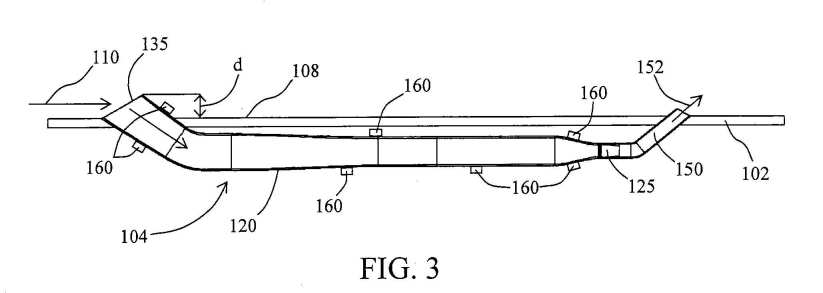
Figure 4 is a cross-sectional view of a portion of another embodiment of a power system of a skin structure, according to another embodiment of the present invention.

Figure 5 illustrates an embodiment of a turbine/generator of a power system of a skin structure, according to another embodiment of the present invention.

Figure 6 illustrates another embodiment of a turbine/generator of a power system of a skin structure, according to another embodiment of the present invention.

Figure 7 illustrates an embodiment of a turbine of the turbine/generator of Figure 6.

Figure 8 is a perspective view of an interior of another embodiment of a skin structure, according to another embodiment of the present invention.

Figure 9 is a cross-sectional view of a portion of a power system of the skin structure of Figure 8, according to another embodiment of the present invention.

DETAILED DESCRIPTION
In the following detailed description of the present embodiments, reference is made to the accompanying drawings that form a part hereof, and in which are shown by way of illustration specific embodiments that may be practiced. These embodiments are described in sufficient detail to enable those skilled in the art to practice disclosed subject matter, and it is to be understood that other embodiments may be utilized and that process, electrical or mechanical changes may be made without departing from the scope of the claimed subject matter. The following detailed description is, therefore, not to be taken in a limiting sense, and the scope of the claimed subject matter is defined only by the appended claims and equivalents thereof.
Figure 1 is a perspective view of an exterior of a skin structure 100, according to an embodiment. Figure 2 is a perspective view of an interior of skin structure 100. Skin structure 100 may include a skin 102. For one embodiment, skin 102, and thus skin structure 100, may form a portion of an outer covering of a stationary structure, such as a roof and/or sides of a building. As such, an interior surface 107 (Figure 2) of skin 102, and thus skin structure 100, may form a portion of an interior surface of the stationary structure, and an exterior surface 108 (Figure 1) of skin 102, and thus skin structure 100, may form a portion of an exterior surface of the stationary structure.
For another embodiment, skin 102, and thus skin structure 100, may form a portion of an outer covering of a vehicle, such as a ground or aerial (manned or unmanned) motor vehicle, e.g., an automobile, airplane, etc., or a marine or submarine (manned or unmanned) motor vehicle, e.g. a boat, submarine, etc. As such, interior surface 107 of skin 102, and thus skin structure 100, may form a portion of an interior surface of the vehicle, and exterior surface 108 of skin 102, and thus skin structure 100, may form a portion of an exterior surface of the vehicle. Skin structure 100 includes a power generation system 104 attached to the skin and located on an interior side of skin 102. Power generation system 104 converts kinetic energy of a fluid-flow 110, e.g., a water-flow or airflow, moving relative to and over exterior surface 108 of skin 102, and thus of skin structure 100, as shown in Figure 1. For example, the fluid flow may be substantially parallel to exterior surface 108. Note that the portion of power generation system 104 that is located on the interior side of skin structure 100 is hidden from view in Figure 1 and is thus shown using dashed lines in Figure 1.
Fluid-flow 110 may be wind moving past skin structure 100 when skin structure 100 is stationary, such as when skin structure 100 forms an outer covering of a stationary structure. Alternatively, fluid-flow 110 may be an airflow or water-flow relative to a vehicle moving through air or water. As such, fluid- flow 1 10 may be termed a forced fluid- flow.
Power generation system 104 has one or more tubes 120 on the interior side of skin 102 that are communicatively (e.g., fluidly) coupled to a turbine of a turbine/generator 125 formed on the interior side of skin 102. For example, power generation system 104 may include a manifold 130 that is interposed between turbine/generator 125 and a plurality of tubes 120 and that communicatively couples the plurality of tubes 120 to the turbine of turbine/generator 125, as shown in Figures 1 and 2. For one embodiment, pairs of tubes 120 may be coupled to a manifold 140 interposed between manifold 130 and tubes 120. Each manifold 140 communicatively couples its pair of tubes 120 to manifold 130.
Each of tubes 120 has an inlet 135 that opens on the exterior side of skin structure 100. For one embodiment, inlet 135 may have circular cross-section having a diameter on the order of one micron or one nanometer. As such, tubes 120 may be referred to as micro- tubes or nano-tubes, and power generation system 104 may be referred to as a micro-power- generation-system or a nano-power-generation-system. Note that the size of the micro-tubes or nano-tubes is exaggerated in Figures 1 and 2 and may be several orders of magnitude less that the thickness of skin 102 for some embodiments.
During operation, fluid- flow 110 enters tubes 120 though inlets 135. The respective tubes 120 direct their respective flows to the turbine turbine/generator 125. For example, pairs of tubes 120 direct their respective flows to a respective manifold 140. Each manifold 140 combines the flows from the respective pair of tubes 120 and directs the combined flow to manifold 130. Manifold 130 combines the flows from the respective manifolds 140 and directs the combined flow to the turbine of turbine/generator 125. As such, the turbine receives the flow flowing through each of tubes 120.
The flow subsequently flows through the turbine, causing the turbine to rotate. The generator of turbine/generator 125 generates electrical power in response to the rotation of the turbine. That is, the generator converts the rotation of the turbine into electrical power.
The flow exits the turbme, and thus power system 104, through an outlet 150. That is, an outlet of the turbine is fluidly coupled to outlet 150. Outlet 150 may be located on and may open on the exterior side of skin structure 100, and the flow 152 exiting power system 104 through outlet 150 may be returned to the flow 110, as shown in Figure 1.
Alternatively, outlet 150 may be located on and open on the interior side of skin structure 100 so that the flow 152 exiting power system 104 through outlet 150 is directed away from skin structure 100. For another embodiment, outlet 150 may be located in a portion of the stationary structure or vehicle that is not exposed to fluid- flow 110.
For one embodiment, a stationary structure or vehicle may have a plurality of power systems 104. For this embodiment, the power from each power system 104 may be directed to a battery, for example, for storage, such as for auxiliary power, to reduce the power demand of an engine of a motor vehicle, or to reduce the power that needs to be purchased to power a stationary structure, such as a building.
Figure 3 is a cross-sectional view of a portion of power system 104, according to another embodiment. As shown, the flow passage within each tube 120 may be tapered and may converge along the length of the tube from the inlet 135 to turbine/generator 125. That is, the cross-sectional area (perpendicular to the flow direction) of the flow passage within each tube 120 decreases from the inlet 135 to the turbine/generator 125.
Passing the flow through a tube 120 causes the flow to converge and thus accelerate. That is, each tube 120 receives fluid- flow 110 and accelerates fluid-flow 1 10. For embodiments, where manifolds 130 and 140 are used, manifolds 130 and 140 may also have converging flow passages that act to accelerate the flows received thereat. The accelerated flow is delivered to the turbine. Note that the flow velocity within tubes 120, manifold 130, and manifolds 140, may be further increased, e.g., thermally assisted, by a temperature difference that may occur between the exterior and interior sides of skin structure 100, e.g., between the inlets 135 and the inlet to the turbine. The increased flow velocity at the inlet to the turbine allows for shorter turbine blades. For example, the power output of some turbines is proportional to the cubic order of the turbine inlet velocity and is typically proportional to the square of the blade length. This means that since the power output of a turbine is proportional to the cubic order of the turbine inlet velocity and is proportional to the square of the blade length, the turbine can have shorter blades and still have a higher power output.
Shorter blades result in less drag than longer blades and thus result in less energy loss than longer blades. Shorter blades result in lower material costs, installation costs, and maintenance costs compared to longer blades. The shorter blades are less susceptible to defects and failure, take up less space, and generate less noise and vibration than longer blades.
As shown in Figures 1 and 3, the inlet 135 of each tube 120 may extend above exterior surface 108 of skin 102, e.g., at an angle to exterior surface 108. The distance d by which the inlet 135 of each tube 120 extends above exterior surface 108 may be on the order of one micron or one nanometer, so as to not to significantly increase drag. Angling the inlet 135 of each tube 120, as shown in Figures 1 and 3, enables the inlet 135 to capture a portion of fluid-flow 110 and to direct that portion of fluid-flow 110 into the respective tube 120. The outlet 150 of each tube may also extend above exterior surface 108 of skin 102, e.g., at an angle to exterior surface 108, by a distance on the order of one micron or one nanometer, so as to not to significantly increase drag.
Alternatively, inlet 135 and outlet 150 may be flush (e.g., substantially flush) with exterior surface 108, as shown in the cross-sectional view of Figure 4. The fluid-flow 110 in the configuration of Figure 4 may be parallel (e.g., substantially parallel) to exterior surface 108 or may be perpendicular (e.g., substantially perpendicular) to exterior surface 108, as shown in Figure 4. Note that the outlet 150 in the configuration of Figure 4 may be located in a portion of the stationary structure or vehicle that is not exposed to fluid-flow 110, as indicated by the break in Figure 4.
Micro-actuators or nano-actuators 160 may be coupled in physical contact with the outer surface of each tube 120, as shown in Figure 3, and in physical contact with the outer surface manifold 130 and of manifolds 140. Actuators 160 are electrically coupled to a controller (not shown) for receiving electrical signals therefrom. For example, a flow- velocity sensor (not shown), e.g., of skin structure 100, the vehicle, or the stationary structure, might detect a flow velocity of fluid-flow 110 and send a signal indicative of the flow velocity to the controller. For some embodiments, the flow- velocity sensor may sense the velocity of fluid-flow 1 10 relative to exterior surface 108 of skin structure 100. For example, the velocity of fluid-flow 110 may be the wind speed or the velocity of the vehicle that includes skin structure 100. The flow- velocity sensor may be a micro- or nano-sensor.
The controller may apply a voltage to actuators 160, causing the actuators to adjust a shape of the tubes 120, e.g., the diameters of the tubes 120, and/or the shape of manifold 130, e.g., the diameter of manifold 130, and/or the shapes of manifolds 140, e.g., the diameters of manifolds 140, to produce a certain flow velocity at the inlet to the turbine. The controller may also cause the actuators to adjust the diameters of the tubes 120 and/or manifold 130 and/or manifolds 140 to reduce flow losses based on a detected flow velocity of fluid-flow 110. This is similar to control and operation of the actuators in U.S. Patent Application Serial No. 12/466,840 and U.S. Patent Application Serial No. 12/369,949, which show and describe actuators, flow-velocity sensors, and controllers.
Figure 5 illustrates a turbine/generator 525 that may be used for turbine/generator 125 of power system 104 for one embodiment. For example, turbine/generator 525 may include an axial-flow turbine 510 having blades that rotate about a rotational axis 515 that is parallel (e.g., substantially parallel) to the fluid-flow 517, e.g., exiting manifold 130, at the inlet to turbine 510. After the flow flows past turbine 510, it is directed out of power system 104 through outlet 150 (Figures 1 and 3).
An electrical generator 520, such as a 60 Hz AC generator, is coupled (e.g., mechanically coupled) to turbine 120 via a shaft and suitable transmission. For water applications, electrical generator 520 is suitably waterproofed to protect against electrical shorting and corrosion. Alternatively, electrical generator 520 may be located out of the fluid-flow, and the shaft and transmission may convey the rotation to the location of electrical generator 520.
For one embodiment, the size of turbine/generator 525 may be on the order of one micron or one nanometer, and may be referred to as a micro- or nano- turbine/generator. For example, turbine 510 may be a micro- or nano-turbine and have a rotor diameter (e.g., blade tip-to-tip distance) on the order of one micron or one nanometer, and generator 520 may be a micro- or nano-generator and have a size on the order of one micron or one nanometer.
During operation, fluid-flow 517 causes turbine 510 to rotate. The rotation is transferred to generator 520, via the shaft and transmission, thereby causing generator to rotate and generate electrical power.
Figures 6 and 7 illustrate a turbine/generator 625 that may be used for turbine/generator 125 of power system 104 for another embodiment. For example, turbine/generator 625 may include a radial-flow turbine 610 that rotates about a rotational axis 615 (Figure 7) that is parallel (e.g., substantially parallel) to the fluid-flow 617 (Figures 6 and 7), e.g., exiting manifold 130, at the inlet to turbine 610. After entering turbine 610, fluid-flow 617 turns by about 90 degrees and flows with radial-outward component over turbine blades 619 away from rotational axis 615 and toward a periphery 622 of turbine 610, as shown in Figure 7. At the periphery 622, the flow turns by about 90 degrees and flows parallel (e.g., substantially parallel) to axis 615.
The flow exits turbine 610, in a direction parallel (e.g., substantially parallel) to axis 615, through outlets 624 that are formed in a stationary housing 626 that houses turbine 610 and that are located around the periphery 622, as shown in Figures 6 and 7. The flow is then directed out of power system 104 through outlet 150 (Figures 1 and 3). Note that turbine 610 is located within housing 626 and is hidden from view in Figure 7 and is thus shown using dashed lines in Figure 7.
For one embodiment, stationary housing 626 may include a stationary electrical generator (not shown) that generates electrical power from the motion of the tips of blades 619 of turbine 610 or the motion of the periphery 622 of turbine 610 in a manner similar to the WT6000 Wind Turbine Gearless Blade Tip Power System developed by HONEYWELL International, Inc. (Morristown, NJ). For water applications, the electrical generator is suitably waterproofed to protect against electrical shorting and corrosion. Alternatively, turbine 610 may be coupled to an electrical generator by a shaft and suitable transmission in a manner similar to that described above in conjunction with electrical generator 520.
For one embodiment, the size of turbine/generator 625 may be on the order of one micron or one nanometer, and may be referred to as a micro- or nano- turbine/generator. For example, turbine 610 may have a diameter on the order of one micron or one nanometer and may be referred to as a micro- or nano-turbine.
Figure 8 is a perspective view of an interior of a skin structure 800, according to another embodiment. Common reference numbers are used in Figure 8 and Figures 1-3 to identify the same or substantially similar components. Skin structure 800 may include the skin 102 described above in conjunction with Figures 1-3. The power generation system 104, described above in conjunction with Figures 1-3, is located on the interior side of skin structure 800, with the inlets 135 of tubes 120 located on the interior side of skin structure 800.
The temperature of a fluid, such as water or air, on the interior side of skin structure 800 is greater than the temperature of the fluid on the exterior side of skin structure 800. For example, skin structure 800 may form a portion of an outer covering of a stationary structure, such as a roof of a building, where the interior of the building is at a higher temperature than the exterior. As such, interior surface 107 (Figures 8 and 9) of skin 102, and thus skin structure 800, may form a portion of an interior surface of the stationary structure, and exterior surface 108 (Figure 9) of skin 102, and thus skin structure 800, may form a portion of an exterior surface of the stationary structure.
Skin structure 800 may form a portion a covering (e.g., a hood) of an engine compartment of a motor vehicle, where the interior of the engine compartment is at a higher temperature than the exterior of the motor vehicle. For example, interior surface 107 of skin 102, and thus skin structure 800, may form a portion of an interior surface of the engine compartment, and exterior surface 108 of skin 102, and thus skin structure 800, may form a portion of an exterior surface of the engine compartment.
The temperature difference between the interior and exterior produces a fluid-flow 810 on the interior side of skin structure 800 that enters tubes 120 through their respective inlets 135, as shown in Figure 9, a cross-sectional view of a portion of power system 104. That is, the flow 810 is a thermally driven flow. Note that inlets 135 open on the interior side of skin structure 800 and thus open to an interior of the stationary structure or the vehicle.
The fluid flows through each tube 120, into the respective manifolds 140 (Figure 8), and into manifold 130, as described above in conjunction with Figures 1 and 2. The flow subsequently flows through the turbine of turbine generator 125, causing the turbine to rotate. The generator of turbine/generator 125 generates electrical power in response to the rotation of the turbine. The flow exits the turbine, and thus power system 104, through outlet 150 on the exterior side of skin 102, and thus of skin structure 800. That is, an outlet of the turbine may be fluidly coupled to the exterior side of skin 102.
Note that turbine/generator 125 may be the same (e.g., substantially the same) as turbine/generator 525, discussed above in conjunction with Figure 5. Alternatively, turbine/generator 125 may be the same (e.g., substantially the same) as turbine/generator 625, discussed above in conjunction with Figures 6-7.
Note that power system 104, and thus skin structure 800, directs the relatively warm fluid from the interior side to the exterior side while generating electrical power. This acts to ventilate the interior of the stationary structure, such as a warm attic under a roof during the summer, or the interior of a motor vehicle, such as the engine compartment of the motor vehicle. That is, skin structure 800 provides cooling while producing electrical power.
For one embodiment, skin structure 100 and skin structure 800 may be used together on a stationary structure or a motor vehicle.
US2010135766
KINETIC HYDROPOWER GENERATION SYSTEM AND INTAKE THEREFORE
KINETIC HYDROPOWER GENERATION SYSTEM AND INTAKE THEREFORE
Abstract -- A kinetic hydropower generation system has a turbine and a generator coupled to the turbine. An underwater intake nozzle assembly is fluidly coupled to the turbine. For one embodiment, an underwater tower nozzle may be fluidly coupled between the turbine and the underwater intake nozzle assembly. The underwater intake nozzle assembly may include a collector and a converging nozzle.
CROSS REFERENCE TO RELATED APPLICATION
This is a continuation in part of U.S. Patent Application Serial No. 12/369,949 (pending), filed February 12, 2009, titled "TURBINE-INTAKE TOWER FOR WIND ENERGY CONVERSION SYSTEMS," which application is commonly assigned, the entire contents of which are incorporated herein by reference.
FIELD
The present disclosure relates generally to kinetic hydropower generation and, in particular, the present disclosure relates to kinetic hydropower generation systems and intakes therefore.
BACKGROUND
Due to the recent energy problems that have arisen, considerable interest has been given to converting the kinetic energy of fluid flows occurring in nature, e.g., wind flows in wind energy conversion systems and water current flows in kinetic hydropower generation systems, into electrical power. For example, wind energy conversion systems involve directing wind through a turbine. The wind causes the turbine to rotate an electrical generator, causing the electrical generator to produce electrical power.
Kinetic hydropower may be defined as, for example, dam-less hydropower that is converted from energy found in the flowing water currents of oceans, tides, rivers, lakes, and manmade channels or conduits. For example, kinetic hydropower generation systems typically involve submerging a turbine under water and directing flowing water current through the turbine, causing the turbine to rotate an electrical generator for producing electrical power. However, water currents in some bodies of water are too weak for kinetic hydropower generation systems to be cost effective. For example, some hydropower generation systems require current flow velocities of at least about six feet per second in order to generate enough energy for them to be cost-effective.
The electrical power generated from the turbines typically used in wind energy conversion systems and kinetic hydropower generation systems is proportional to cubic order of the flow velocity, e.g., of the water or air, at the turbine inlet. Furthermore, the longer each turbine blade, the higher the power generation. However, long blades are costly, can be subjected to defects and failure, take up a large amount of space, and generate excessive noise and vibration. The electrical power generated from these turbines is directly proportional to the square of the propeller length. However, longer propellers increase not only the cost of material and installation, but also the cost of maintenance. As such, current wind energy conversion systems and kinetic hydropower generation systems typically suffer from low efficiency, high capital cost, unpredictable failures, excessively high noise and vibration, and/or high maintenance.
For the reasons stated above, and for other reasons stated below which will become apparent to those skilled in the art upon reading and understanding the present specification, there is a need in the art for alternatives to existing wind power generation systems and kinetic hydropower generation systems.
SUMMARY
An embodiment of the present invention provides a kinetic hydropower generation system. The kinetic hydropower generation system has a turbine and a generator coupled to the turbine. An underwater intake nozzle assembly is fluidly coupled to the turbine. For one embodiment, an underwater tower nozzle may be fluidly coupled between the turbine and the underwater intake nozzle assembly. The underwater intake nozzle assembly may include a collector and a converging nozzle.
BRIEF DESCRIPTION OF THE DRAWINGS
Figure 1 is a cut-away perspective view of an embodiment of an energy conversion system, according to an embodiment of the present invention.

Figure 2 is an enlarged view of a portion of Figure 1 , according to another embodiment of the present invention.

Figure 3 illustrates an embodiment of a kinetic hydropower generation system submerged in a body of water, according to another embodiment of the present invention.

Figure 4 is a perspective view of another embodiment of an energy conversion system, according to another embodiment of the present invention.

Figure 5 illustrates another embodiment of a kinetic hydropower generation system submerged in a body of water, according to another embodiment of the present invention.

Figure 6 is an enlarged view of a portion of Figure 5, according to another embodiment of the present invention.
Figure 7 a perspective view of an embodiment of an array of energy conversion systems, according to another embodiment of the present invention.

DETAILED DESCRIPTION
In the following detailed description of the present embodiments, reference is made to the accompanying drawings that form a part hereof, and in which are shown by way of illustration specific embodiments that may be practiced. These embodiments are described in sufficient detail to enable those skilled in the art to practice disclosed subject matter, and it is to be understood that other embodiments may be utilized and that process, electrical or mechanical changes may be made without departing from the scope of the claimed subject matter. The following detailed description is, therefore, not to be taken in a limiting sense, and the scope of the claimed subject matter is defined only by the appended claims and equivalents thereof. Figure 1 is a cut-away perspective view of an energy conversion system 100, such as a wind energy conversion system or a kinetic hydropower generation system. When operating as kinetic hydropower generation system, energy conversion system 100 is submerged within a body of water, such as a river, ocean, lake, or a manmade channel, etc., as is shown in Figure 3 for a kinetic hydropower generation system 300. Energy conversion system 100 includes a turbine-intake tower 110, a turbine 120 fluidly coupled to turbine- intake tower 110, and an electrical generator 130, such as a 60 Hz AC generator, coupled (e.g., mechanically coupled) to turbine 120.
For underwater applications, electrical generator 130 is suitably waterproofed to protect against electrical shorting and corrosion. To help guard against water corrosion turbine-intake tower 110 and the blades of turbine 120 may be fabricated from a suitable polymer or may be polymer-coated metal. For other embodiments, turbine 120 and electrical generator 130 may be located above water, such as on land or on a platform floating on a body of water, and the water exiting turbine-intake tower 110 may conveyed to turbine 120, e.g., by conduits, such as pipes. Turbine-intake tower 110 has an inlet 140 and an outlet 142. Air or water enters turbine-intake tower 110 through inlet 140 flows through turbine-intake tower 110 and exits turbine-intake tower 110 through outlet 142. The air or water exiting though outlet 142 passes over the blades of turbine 120, as shown in Figure 2, an enlarged view of outlet 142, turbine 120, and generator 130, causing turbine 120 to rotate. Rotation of turbine 120 rotates the generator 130 via a suitable transmission (not shown) that mechanically couples turbine 120 to generator 130.
Inlet 140 may have a screen or other devices to prevent the entry of birds or other airborne objects for wind applications or the entry offish or other water-born objects for underwater applications. Any conventional bird-catcher or fish-catcher device may be used in this system. Turbine-intake tower 110 includes an intake nozzle assembly 143 that includes a converging intake nozzle 144 and that may include an integral collector 146 that is contiguous with converging intake nozzle 144. For another embodiment, intake nozzle assembly 143 may be rotatably coupled to a support column 150 of turbine- intake tower 110 by means of a bearing 152. Support column 150 is substantially vertical and acts to support intake nozzle assembly 143 at a vertical height H above ground level 154, where the height H is measured from a central longitudinal axis 156 of intake nozzle assembly 143. Note that ground level 154 may correspond to the floor or the bottom 354 (Figure 3) of the body of water in which turbine-intake tower 110 is submerged.
For wind applications, the height H may be about the same height as the hub of a turbine of a conventional wind turbine system, where the turbine is mounted atop a tower. For example, the height H may be about 100 to about 200 feet.
For some underwater applications, the height H may be sufficient to position intake nozzle assembly 143 at a distance above the bottom 354 of the body of water where the flow velocity is at or near its highest. For example, for rivers or shallow-water regions near shorelines, the current flow velocity increases toward the surface of the water. For example, in breakwater zones near shorelines, the flow velocity near the surface is higher due to wave action and tidal flow. As such, intake nozzle assembly 143 is positioned to capture tidal flow and wave-induced current.
Support column 150 has a base 151 that may directly contact the ground at ground level 154. Alternatively, for wind applications, intake tower 110 may be positioned on and may be in direct contact with a platform floating on water, for example, for offshore application, in which case ground level 154 would correspond to the surface of the platform. Turbine 120 and generator 130 are located at or near ground level, e.g., at about the same vertical level as base 151 and about the same vertical level as outlet 142, as shown in Figures 1 and 2. For example, turbine 120 and generator 130 may be located on the bottom 354 of the body of water, as shown in Figure 3.
Intake nozzle assembly 143 may be substantially horizontal. That is, central longitudinal axis 156 of intake nozzle assembly 143 may be substantially horizontal. Central longitudinal axis 156 may be substantially parallel to the direction of the wind or water current and thus the direction of the air or water entering intake nozzle assembly 143. The inner surfaces of nozzle assembly 143 are made of a smooth material in order to reduce losses due to surface friction.
Collector 146 extends in the direction of central longitudinal axis 156 from an inlet plane 160 of turbine-intake tower 110 to the dashed line 162, which marks the exit of collector 146. The flow passage within collector 146 is substantially uniform in size between inlet plane 160 and the exit 162 of collector 146, i.e., the cross-sectional area (perpendicular to the flow direction) of the flow passage within collector 146 is substantially uniform between inlet plane 160 and the exit 162. When inlet 140 is facing the wind or the direction of the water current and central longitudinal axis 156 is substantially parallel to the wind or water flow direction, collector 146 collects the wind or water flow. Intake nozzle 144 is fluidly coupled to collector 146. The flow passage within intake nozzle 144 converges (e.g., tapers) in the direction of central longitudinal axis 156, starting at the exit 162 of collector 146 and ending at an entrance to an elbow 164. That is, the cross-sectional area (perpendicular to the flow direction) of the flow passage within intake nozzle 144 decreases between exit 162 of collector 146 and elbow 164, as shown in Figure 1. Intake nozzle 144 acts to increase the flow velocity between exit 162 of collector 146 and elbow 164. That is, passing the flow through intake nozzle 144 causes the flow to converge and thus accelerate. Note that intake nozzle 144 receives the wind or water current from collector 146 and accelerates the wind or water current.
Elbow 164 is interposed between intake nozzle assembly 143 and bearing 152. As such, bearing 152 rotatably connects an upper end of support column 150 to elbow 164. Support column 150 is hollow. A converging tower nozzle 170 (e.g., a column nozzle) is located within an interior of support column 150 and may extend from bearing 152 to an elbow 172 that is coupled to an outlet duct 174 (e.g., sometimes referred to as the turbine inlet duct) that leads to outlet 142. As such, tower nozzle 170 is fluidly coupled to intake nozzle 144 and outlet duct 174.
Tower nozzle 170 may be substantially vertical. For example, a central longitudinal axis 176 of tower nozzle 170 is substantially vertical and is substantially perpendicular to central longitudinal axis 156 of intake nozzle assembly 143, as shown in Figure 1. The flow passage within tower nozzle 170 converges (e.g., tapers) in the direction of central longitudinal axis 176, e.g., in the downward vertical direction, starting at the exit of elbow 164 and ending at an entrance to elbow 172. That is, the cross-sectional area (perpendicular to the flow direction) of the flow passage within tower nozzle 170 decreases between elbow 164 and elbow 172, as shown in Figure 1. Tower nozzle 170 acts to increase the flow velocity between elbow 164 and elbow 172. That is, passing the flow through tower nozzle 170 causes the flow to converge and thus accelerate.
Outlet duct 174 may be substantially horizontal. For example, a central longitudinal axis 178 of outlet duct 174 may be substantially horizontal and may be substantially perpendicular to central longitudinal axis 176 of tower nozzle 170 and substantially parallel to central longitudinal axis 156 of intake nozzle assembly 143, as shown in Figure 1. Elbow 172 and outlet duct 174 direct the flow from tower nozzle 170 onto the blades of turbine 120. The flow velocity at outlet 142, i.e., the outlet of turbine-intake tower 110 and of duct 174, is the turbine inlet velocity.
Turbine 120 has a rotatable shaft 180 that is substantially horizontal, i.e., shaft 180 has a central longitudinal axis 182 that is substantially horizontal and that is substantially parallel to central longitudinal axis 178 of outlet duct 174. Turbine blades 181 (Figure 2), e.g., three or more, are mechanically coupled to shaft 180. Note that central longitudinal axis 182 is the rotational axis of turbine 120 about which shaft 180 and the blades rotate.
Turbine 120 may be referred to as a horizontal-axis turbine. Central longitudinal axis 178 of outlet duct 174 central longitudinal axis 182 of shaft 180 maybe substantially collinear. Note that for this embodiment, turbine-intake tower 110 has a substantially horizontal outlet. Also note that the direction of the flow exiting outlet duct 174 is substantially parallel to the central longitudinal axis 182 of shaft 180 and thus the rotational axis of turbine 120.
Alternatively, for another embodiment, elbow 172 and outlet duct 174 may be removed, and a turbine 120 may be located at the exit of tower nozzle 170 so that its shaft 180 is substantially vertical. For example, central longitudinal axis 182 of shaft 180 is substantially vertical and is substantially parallel and substantially collinear to central longitudinal axis 176 of tower nozzle 170. In this embodiment, turbine 120 may be referred to as a vertical-axis turbine. Note that the flow velocity at the exit of tower nozzle 170 is the turbine inlet velocity for this embodiment and that turbine 120 receives the fluid flow directly from tower nozzle 170. As such, the exit of tower nozzle 170 is the outlet of turbine-intake tower 110, meaning that turbine-intake tower 110 has a substantially vertical outlet. Again, the direction of the flow exiting tower nozzle 170 is substantially parallel to the vertically oriented central longitudinal axis 182 of shaft 180 and thus the rotational axis of turbine 120. Elbow 164 has a radius of curvature that acts to keep flow losses relatively low.
This means that the flow velocity at the exit of intake nozzle 144 and the entrance to tower nozzle 170 is substantially the same. Elbow 172 also has a radius of curvature that acts to keep flow losses relatively low. In addition, the losses in outlet duct 174 are relatively small. Therefore, the flow velocity at the exit of tower nozzle 170 and the exit of outlet duct 174 are substantially the same. As such, intake nozzle 144 and tower nozzle 170 work together to increase the flow velocity from the velocity at inlet 140 (the wind or water current velocity) to the velocity at outlet 142 (the turbine inlet velocity).
The inner surfaces of the elbows, tower nozzle 170, and outlet duct 174 are made of a smooth material in order to reduce losses due to surface friction. Turbulence suppressors may be implemented to reduce turbulence in elbows 164 and 172, intake nozzle assembly 143, tower nozzle 170, and outlet duct 174 that may result from imperfections and anomalies in elbows 164 and 172, intake nozzle assembly 143, tower nozzle 170, and outlet duct 174.
Note that the flow (wind or water current) velocity at inlet 140 is substantially the same as the flow (wind or water current) velocity at the inlet of a turbine of a conventional wind energy conversion or a conventional kinetic hydropower generation system. This means that the flow velocity at the inlet to turbine 120 is higher than the flow velocity (wind or water current) at the inlet of the turbines of conventional wind energy conversion systems and conventional kinetic hydropower generation systems, owing to increasing the flow velocity using intake nozzle 144 and tower nozzle 170. The increased velocity at the inlet to turbine 120 allows for shorter turbine blades compared to the turbine blades for the turbines of conventional wind energy conversion systems and conventional kinetic hydropower generation systems.
For example, the power output of a turbine is typically proportional to the cubic order of the turbine inlet velocity and is typically proportional to the square of the blade length. Since the turbine inlet velocity, as result of turbine-intake tower 110, of the wind energy conversion systems and the kinetic hydropower generation systems of the present disclosure is higher than the wind or water current velocity at the inlet of a turbine of a conventional wind energy conversion system or a conventional kinetic hydropower generation system, the wind energy conversion systems and the kinetic hydropower generation systems of the present disclosure have a higher power output than conventional wind energy conversion systems and conventional kinetic hydropower generation systems for the same blade length. This means that since the power output of a turbine is proportional to the cubic order of the turbine inlet velocity and is proportional to the square of the blade length, the turbines of the wind energy conversion systems and the kinetic hydropower generation systems of the present disclosure can have shorter blades than the blades of the turbines of conventional wind energy conversion systems and conventional kinetic hydropower generation systems and still have a higher power output.
Shorter blades result in less drag than longer blades and thus result in less energy loss than longer blades. Shorter blades result in lower material costs, installation costs, and maintenance costs compared to the longer blades of the turbines of conventional wind energy conversion systems and conventional kinetic hydropower generation systems. The shorter blades are less susceptible to defects and failure, take up less space, and generate less noise and vibration than the longer blades of the turbines of conventional wind energy conversion systems and conventional kinetic hydropower generation systems.
Actuators 186, e.g., piezoelectric actuators, may be physically coupled to the outer surface of intake nozzle assembly 143, e.g., the outer surface of intake nozzle 144 and/or the outer surface of collector 146, as shown in Figures 1, 3, and 4. For example, actuators 186 may be coupled in direct physical contact with the outer surface of intake nozzle 144 and/or the outer surface of collector 146. Actuators 186 are electrically coupled to a controller 190 for receiving electrical signals from controller 190.
A flow- velocity sensor 192, may be mounted on an outer surface of turbine-intake tower 110 at or near the top of turbine-intake tower 110 for sensing the velocity of the wind or water current. For example, flow- velocity sensor 192 may be mounted on elbow 164, as shown in Figure 1, or on intake nozzle assembly 143. Flow-velocity sensor 192 may be electrically coupled to controller 190 for sending electrical signals to controller 190 indicative of the sensed wind or water current flow velocity. Note that although flow- velocity sensor 192 is positioned behind inlet 140, flow- velocity sensor 192 is positioned at a vertical level that is sufficiently above the upper surface of intake nozzle assembly 143 so as to sense the prevailing wind or water current flow velocity external to turbine-intake tower 110. As a result, flow- velocity sensor 192 effectively measures the prevailing wind or water current flow velocity upstream of inlet 140.
A flow-direction sensor 194, may be mounted on an outer surface of turbine- intake tower 110 at or near the top of turbine-intake tower 110 for sensing the direction of the wind or water current flow. Flow-direction sensor 194 catches the wind or water flow such that the water current flow rotates intake nozzle assembly 143 relative to support column 150 such that inlet 140 is directed into the wind or water current flow, e.g., so that central longitudinal axis 156 of intake nozzle assembly 143 is substantially parallel to the wind or water flow direction. Flow-direction sensor 194 may be electrically coupled to controller 190 for sending electrical signals to controller 190 indicative of the sensed wind or water flow direction.
Kinetic hydropower generation systems that are configured to convert the kinetic energy of tidal flows into electrical power are exposed to bidirectional currents. That is, the current flow is in one direction when the tide comes in and in an opposite direction when the tide goes out. Flow-direction sensor 194 catches the incoming or outgoing tide and rotates intake nozzle assembly 143 so that inlet 140 is directed into the incoming or outgoing tide. Note that rivers that flow into the oceans act as tidal channels where the current direction changes with the tide. For another embodiment, upon receiving electrical signals from flow-direction sensor 194, controller 190 may send electrical signals to a yaw motor (not shown) located adjacent bearing 152. A yaw drive (not shown) may mechanically couple the yaw motor to intake nozzle assembly 143. The signals instruct the yaw motor to activate the yaw drive that in turn rotates intake nozzle assembly 143 relative to support column 150 and tower nozzle 170 such that inlet 140 is directed into the wind or the water current flow.
In response to receiving signals indicative of the wind or water flow velocity from flow- velocity sensor 192, controller 190 may send electrical signals to actuators 186.
Actuators 186 may then adjust the shape (e.g., contour) of intake nozzle assembly 143 by exerting forces on the outer surface of intake nozzle assembly 143 based on the wind or water flow velocity. That is, the shape of collector 146 and/or the shape of intake nozzle 144 may be adjusted based on the wind or water flow velocity. For example, actuators 186 may adjust the diameter of collector 146 and/or a diameter of intake nozzle 144.
Controller 190 may store voltage values corresponding to the voltages that need to be applied to an actuator 186 to set a diameter at a certain numerical value. The certain numerical value may correspond to a diameter that provides a certain increase in velocity and/or reduced losses for a certain wind or water flow velocity for a certain power output. For example, flow-velocity sensor 192 might detect a wind or water flow velocity and send a signal indicative of the wind or water flow velocity to controller 190. Controller 190 may then determine the required velocity at outlet 142 to produce a certain power. Controller 190 may further determine how much voltage needs to be applied to an actuator 186 to adjust the diameter of intake nozzle 144 and/or collector 146 in order to produce the required velocity at outlet 142 for the detected wind or water flow velocity. Similarly, controller 190 may adjust the diameter of collector 146 and/or a diameter of intake nozzle 144 to reduce flow losses based on a detected wind or water flow velocity.
In the event that flow- velocity sensor 192 detects a wind or water flow velocity that is excessive, e.g., above a certain value, and that could cause damage to turbine 120 and/or generator 130, controller 190 might send a signal to solenoid activated bleed-off valves 193 located at the elbows 164 and 172 that causes the bleed-off valves 193 to open. Opening the bleed-off valves 193 causes a portion of the flow to be bled off, reducing the turbine inlet velocity to an acceptable value. For example, a portion of the flow may be bled off between intake nozzle assembly 143 and tower nozzle 170, and a portion of the flow may be bled off between tower nozzle 170 and turbine 120. For one embodiment, the bled-off flows may be directed to another turbine. After intake nozzle assembly 143 is rotated such that inlet 140 is directed into the wind or water current flow and central longitudinal axis 156 is substantially parallel to the wind or water current flow direction, collector 146 collects the wind or water current flow and directs the wind or water flow to intake nozzle 144. Intake nozzle 144 accelerates the wind or water flow. Elbow 164 receives the accelerated wind or water flow from intake nozzle 143 and directs the wind or water current flow to tower nozzle 170 by turning the wind by substantially 90 degrees. Tower nozzle 170 further accelerates the wind or water flow. For one embodiment, elbow 172 receives the further accelerated wind or water flow from tower nozzle 170 and directs the wind or water flow to outlet duct 174 by turning the wind or water flow by substantially 90 degrees. Outlet duct 174 directs the wind or water flow to turbine 120, e.g., when turbine 120 is a horizontal-axis turbine. For another embodiment, e.g., when turbine 120 is a vertical-axis turbine, turbine 120 may receive the wind or water flow directly from tower nozzle 170 while the wind or water is flowing substantially vertically downward. For another embodiment, the outputs of two or more turbine-intake towers 110 may be sent to a single turbine 120 coupled to a single generator 130, as shown for an energy conversion system 400, such as a wind energy conversion system or a kinetic hydropower generation system, in Figure 4. In particular, the outlet ducts 174 are coupled to a single outlet 442 directed at turbine 120. Note that the flow velocity at outlet 442 is the turbine inlet velocity. Common numbering is used in Figures 1 and 4 to identify components common to Figures 1 and 4.
When energy conversion system 400 acts as a kinetic hydropower generation system, energy conversion system 400 is submerged under water. For another embodiment, only turbine-intake towers 110 are submerged under water; and the single turbine 120 and generator 130 are located on land or on a floating platform; and the water exiting the single outlet 442 is conveyed to the turbine 120, e.g., by conduits, such as pipes.
Figure 5 illustrates a kinetic hydropower generation system 500 submerged in a body of water, such as a river, ocean, lake, or a manmade channel, etc. Common numbering is used in Figures 1-3 and 5 to identify components common to Figures 1-3 and 5. Kinetic hydropower generation system 500 includes the nozzle assembly 143, as described above in conjunction with Figure 1, positioned on bottom 354 of the body of water. Inlet 140 of nozzle assembly 143 is directed into the water current flow. Intake nozzle assembly 143 may be substantially parallel to bottom 354 of the body of water. That is, central longitudinal axis 156 of intake nozzle assembly 143 maybe substantially parallel to bottom 354 of the body of water. Central longitudinal axis 156 may be substantially parallel to the direction of the water current and thus the direction of water entering intake nozzle assembly 143.
The central longitudinal axis 182 of turbine shaft 180 (Figure 2) is substantially parallel to and is substantially collinear with longitudinal axis 156, as shown in Figure 6, an enlarged view of outlet 542 of intake nozzle assembly 143, turbine 120, and generator 130. As indicated above in conjunction with Figures 1 and 2, central longitudinal axis 182 is the rotational axis of turbine 120. Note that the direction of the flow exiting intake nozzle assembly 143 is substantially parallel to the central longitudinal axis 182 of shaft 180.
Nozzle assembly 143 operates as described above in conjunction with Figure 1. That is, collector 146 collects the water current flow and directs the water flow to intake nozzle 144. Intake nozzle 144 accelerates the water flow and directs the accelerated water flow onto blades of turbine 120, causing turbine 120 to rotate generator 130 so that generator 130 generates electrical power.
Nozzle assembly 143 may include the flow- velocity sensor 192 (Figure 1) that is electrically coupled to controller 190 for sending electrical signals to controller 190 indicative of the sensed water current flow velocity. Controller 190 may cause actuators 186 to adjust the diameter of collector 146 and/or a diameter of intake nozzle 144 based on the detected water flow velocity, as described above.
For example, controller 190 may determine how much voltage needs to be applied to an actuator 186 to adjust the diameter of intake nozzle 144 and/or collector 146 in order to produce the required velocity at outlet 542 for the detected water flow velocity. Controller 190 may further adjust the diameter of collector 146 and/or a diameter of intake nozzle 144 to reduce flow losses based on a detected water flow velocity.
For another embodiment, the outputs of two or more nozzle assemblies 143 of a kinetic hydropower generation system may be sent to a single turbine 120 coupled to a single generator 130 in a manner similar to that shown in Figure 4. For example, the outlets 542 of the two or more nozzle assemblies 143 may be coupled to a single outlet, e.g., similar to outlet 442 in Figure 4, directed at turbine 120. Figure 7 is a perspective view of an array 700 of energy conversion systems 100, as described above in conjunction with Figures 1 and 2. Array 700 may be located above ground as a portion of a wind farm or may be submerged in a body of water as a portion of an underwater kinetic-hydropower- generation farm. The turbines and generators of the respective energy conversion systems 100 of the underwater kinetic-hydropower- generation farm may be located underwater or above water, e.g., on land or on a floating platform.
A wind farm may include a plurality of above-ground turbine-intake towers 110 coupled to a single outlet directed at a single turbine, as shown in Figure 4. An underwater kinetic-hydropower-generation farm may include a plurality of underwater turbine-intake towers 110 coupled to a single outlet directed at a single turbine. The single turbine of the underwater kinetic-hydropower-generation farm may be located on land or on a floating platform, and the water exiting the single outlet may be conveyed to the on-land turbine, e.g., by conduits, such as pipes.
For another embodiment, an underwater kinetic-hydropower-generation farm may include an array of underwater kinetic hydropower generation systems 500 (Figure 5). The turbines and generators of the respective energy conversion systems 500 maybe located underwater or above water, e.g., on land or on a floating platform. Alternatively, an underwater kinetic-hydropower-generation farm may include an array of nozzle assemblies 143, where nozzle assemblies of the array are coupled to a single outlet directed at a single turbine, where the single turbine and the generator coupled thereto are underwater or are above water, e.g., on land or on a floating platform.
Accelerating water current flow using the nozzle assembly 143 of Figure 5 or accelerating either wind or water current flow using the turbine-intake towers 110 of Figures 1, 3, 4, and 7 acts to reduce the length of the turbine blades. Reducing the length of the turbine blades acts to reduce the initial capital cost, installation cost, and the lifetime maintenance cost of the turbine. Accelerating the water current flow using either nozzle assembly 143 or turbine-intake tower 110 acts to increase water current flow velocities that might otherwise be too low to be cost effective to levels that can be cost effective.
Locating the turbine and generator above water as described in some of the embodiments of the disclosed kinetic hydropower generation systems enables easier to access the turbine and generator than the underwater turbines and generators in conventional kinetic hydropower generation systems. This acts to reduce maintenance costs. Above-water turbines and generators are not subjected to the type of water-induced corrosion as is common in under-water turbines and generators. Above-water generators are not subject to the type of water-induced shorting that can occur with underwater generators.
CONCLUSION
Although specific embodiments have been illustrated and described herein it is manifestly intended that the scope of the claimed subject matter be limited only by the following claims and equivalents thereof.