Bamdad
BAHAR
Electrochemical Compression
Electrochemical Compression
ElectroChemical
Compression
Xergy’s technology for a new class of clean, green compressor for refrigeration and cooling (code named Kuel-cell ) is potentially transformational and disruptive for the conventional refrigeration industry. It uses stable and well-understood technology from the Fuel-cell industry, in a novel fashion that simply requires electricity to produce refrigeration without the need for motors or CFC refrigerants. Devices utilizing such technology could be deployed in any number of commercial, residential and automotive applications in a cost-effective, efficient and environmentally-friendly manner.
Xergy’s green refrigeration technology devices would produce small-volume, lightly pressurized hydrogen from electricity, in a sealed unit to drive a motor-less, non-CFC refrigeration cycle. It leverages existing proton-exchange-membrane (PEM) technology, and hydrogen’s excellent thermodynamic characteristics and ability to co-exist with other fluids, to create a refrigeration-cycle. Xergy refers to this refrigeration approach as Electro-chemical (EC)
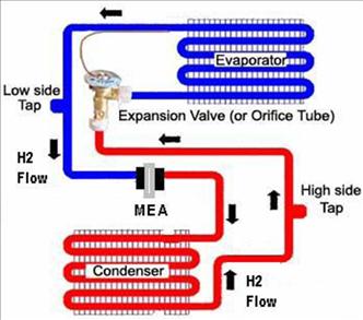
An electrochemical (EC) compressor and heat pump system includes an EC cell and a mixed gas refrigerant-based cooling system. The EC cell is capable of producing high pressure hydrogen gas from a mixed fluid system including an electrochemically-active component such as hydrogen and at least one refrigerant fluid. The cooling system can include a condenser, compressor, and evaporator in thermal communication with an object to be cooled. Hydrogen gas is pressurized across the membrane electrode assembly (MEA).
The hydrogen gas enters a gas space, where it is compressed into a vapor refrigerant. As the vapor refrigerant is compressed, it is forced through the condenser where the refrigerant is liquefied. The liquid refrigerant then passes through the evaporator where the liquid refrigerant is evaporated by absorbing heat from the object to be cooled. The mixed fluids then enter the EC cell where hydrogen is pressurized again.
The core technology in the device is a PFSA membrane as the compressor component in a typical 4-stage refrigeration cycle system. The surface being cooled will act as an evaporator component. A micro-machined orifice in the device will act as a refrigeration-cycle expansion valve. Condensation will occur above the PFSA membrane surface, on a heat exchanger surface elsewhere in the device (see Figure 1).
Heat absorption: Cool Liquid mixture + hydrogen gas circulate internally at the interface between the item to be cooled and the device itself (and absorb heat).
Compression: Above, the membrane and electrode assembly absorbs the liquid and hydrogen gas and transports them both to the other side, pressurizing the mixture. The pressure of Hydrogen gas is several PSI above atmospheric pressure.
Condensation: The slightly pressurized fluids release energy to the environment at a higher rate than the surface of the heat absorption region, in a high surface-area, heat exchanger.
Expansion: The slightly pressurized Gas/Liquid fluid mixture is conveyed through an orifice where it expands and cools down with higher liquid content.
ElectroChemical Compression ...
1. Can be used as alternative in Household Refrigerators and AC, and Auto-AC
2. Requires no CFC’s refrigerants (or other forms of GHG-producing refrigerants)
3. Requires no electric-motor for its compressor
4. Is 2x to 3x more efficient than current technology
5. Requires no Rare Earth Metals (REMs)
6. Has a highly flexible form-factor
7. Produces little or no noise
8. Requires less manufacturing and less maintenance in operation
9. Can be designed in sizes from 50 Watts to 5000 Watts
10. Is modular so a series of units can be effectively used
11. Supports part-load operation without performance penalty
http://www.prweb.com/releases/2011/6/prweb8598592.htm
Xergy Inc,
Wins GE Ecomagination Award

Bamdar BAHAR
Bamdar BAHAR
Xergy Inc. a high technology company based in Georgetown Delaware is proud to announce that it has been selected as one of five winners of GE’s ecomagination global innovation award.
GE is driving a global energy transformation with a focus on innovation and R&D investment to accelerate the development and deployment of clean energy technology. Since its inception in 2005, 110 ecomagination-approved products have been brought to market with revenues reaching $18 billion in 2010. The company will invest $10 billion in R&D over five years and double operational energy efficiency while reducing greenhouse gas emissions and water consumption. As part of the initiative, GE launched “GE ecomagination Challenge: Powering the Grid”, a $200 million financial commitment challenging innovators to join in developing clean energy technologies. It is extending this Challenge with the “GE ecomagination Challenge: Powering Your Home,” to develop technologies that help households manage their energy usage. For more information, visit the ecomagination website at http://ge.ecomagination.com/index.html.
Bamdad Bahar, co-founder and inventor of Xergy’s technology visited New York on June 24rd to formally receive the award with co-founder Richard L. Williams. Bamdad made the following statement to industry media during the internationally televised event:
“I am very proud of our team, and GE’s recognition of our hard work. This has been a very long process for us of quietly doing our work while operating our other businesses. Quite frankly without an incredible business community in Delaware, it would have been impossible to get this far. First of all Delaware is home to the global leaders in the solid state ion exchange membrane technology with Dupont, Gore, and Ion-Power all based there. Secondly, it is also home to the University of Delaware that has one of the leading Chemical Engineering Departments in the world. It is astounding that we were able to access renowned Professors like Stanley Sandler with a simple phone call and ended up very quickly conducting very complex thermodynamic modeling that supported our development. It is important to note too, that without the opportunities afforded to us by many local companies such as Perdue Farms, who strongly believe in supporting local communities, we simply would not have been able to devote the resources to bring our inventions to this stage. The Delaware Economic Development Office was instrumental in assisting us with permitting for our labs; and our local community bank, County Bank of Rehoboth has been pivotal with further assistance to accelerate our programs. In truth, this really is a tribute not to us, but to the whole commercial infrastructure in Delaware. We hope to be able to place Delaware on the leading edge of a new global industrial revolution creating a sustainable future for our planet and transforming how the world creates, connects to and uses energy.”
Xergy Inc was founded in 2009 to commercialize a series of patents based on “electrochemical compression” to launch a new class of clean, green compressors for the refrigeration and cooling industry. Xergy’s technology is based on utilizing electrochemical compression of clean non-GHG (non-Green-House-Gas) depleting refrigerants. This technology provides for highly-efficient, noiseless, vibration free, modular and scalable Cooling Systems. This technology is potentially transformational and disruptive for the conventional refrigeration industry. It uses stable and well-understood technology from the Fuel-cell industry in a novel fashion that simply uses electricity to produce refrigeration without the need for motors or polluting refrigerants. Devices utilizing this technology could be deployed in any number of commercial, residential and automotive applications in a cost-effective, efficient and planet-friendly manner. It leverages existing proton-exchange-membrane technology with hydrogen’s excellent thermodynamic characteristics and ability to co-exist with other fluids, to operate a clean and efficient refrigeration cycle.
Funds from this award will be used to expand our facilities and hire additional scientists. For more information, please call Cassandra Asher at 302-856-3500.
Xergy is based at 310 North Race Street, Georgetown, DE 1994
Patents
Self-Contained Electrochemical Heat Transfer System
US2011127018
Tubular System for Electrochemical Compressor
US2011108246
ELECTROCHEMICAL COMPRESSOR AND REFRIGERATION SYSTEM
WO2010065423
Solid electrolyte composite for electrochemical reaction apparatus
US7931995
Solid electrolyte composite for electrochemical reaction apparatus
US6635384
Self-Contained
Electrochemical Heat Transfer System
US2011127018
US2011127018
TECHNICAL FIELD
[0002] The disclosed subject matter relates to a self-contained heat transfer system having an electrochemical compressor.
BACKGROUND
[0003] The function of both heat transfer systems such as refrigeration cycles and heat pumps is to remove heat from a heat source or reservoir at low temperature and to reject the heat to a heat sink or reservoir at high temperature. While many thermodynamic effects have been exploited in the development of heat pumps and refrigeration cycles, the most popular today is the vapor compression approach. This approach is sometimes called mechanical refrigeration because a mechanical compressor is used in the cycle.
[0004] Mechanical compressors account for approximately 30% of a household's energy requirements and thus consume a substantial portion of most utilities' base load power. Any improvement in efficiency related to compressor performance can have significant benefits in terms of energy savings and thus have significant positive environmental impact. In addition, there are increasing thermal management problems in electronic circuits, which require smaller heat pumping devices with greater thermal management capabilities.
[0005] Vapor compression refrigeration cycles generally contain five important components. The first is a mechanical compressor that is used to pressurize a gaseous working fluid. After proceeding through the compressor, the hot pressurized working fluid is condensed in a condenser. The latent heat of vaporization of the working fluid is given up to a high temperature reservoir often called the sink. The liquefied working fluid is then expanded at substantially constant enthalpy in a thermal expansion valve or orifice. The cooled liquid working fluid is then passed through an evaporator. In the evaporator, the working fluid absorbs its latent heat of vaporization from a low temperature reservoir often called a source. The last element in the vapor compression refrigeration cycle is the working fluid itself.
[0006] In conventional vapor compression cycles, the working fluid selection is based on the properties of the fluid and the temperatures of the heat source and sink. The factors in the selection include the specific heat of the working fluid, its latent heat of vaporization, its specific volume and its safety. The selection of the working fluid affects the coefficient of performance of the cycle.
SUMMARY
[0007] In some general aspects, a self-contained heat transfer system conveys heat from a first heat reservoir at a relatively low temperature to a second heat reservoir at relatively high temperature, the heat transfer system defining a closed loop that contains a working fluid. The self-contained heat transfer system includes a hermetically-sealed housing that defines an enclosure; a first heat transfer device having an exposed surface configured to be in thermal communication with the first heat reservoir; a second heat transfer device having an exposed surface configured to be in thermal communication with the second heat reservoir; and an electrochemical compressor within the enclosure and between the first and second heat transfer devices, wherein the electrochemical compressor includes one or more electrochemical cells, each electrochemical cell including a gas pervious anode, a gas pervious cathode, and an electrolytic membrane disposed between and in intimate electrical contact with the cathode and the anode.
[0008] Implementations can include one or more of the following features. For example, the first heat transfer device can include at least a part of the housing. The exposed surface of the first heat transfer device can be a surface of the housing. The first heat transfer device can be at least partly within the enclosure. The second heat transfer device can include at least a part of the housing. The exposed surface of the second heat transfer device can be a surface of the housing. The second heat transfer device can be at least partly within the enclosure.
[0009] The first heat transfer device can be configured to transfer heat from the first heat reservoir to the working fluid. The second heat transfer device can be configured to transfer heat from the working fluid to the second heat reservoir.
[0010] The system can also include an expansion space fluidly coupled to the first and second heat transfer devices and configured to reduce a pressure of the working fluid.
[0011] The working fluid can contain one or more components that pass through the electrochemical compressor. The working fluid can contain one or more components that bypass the electrochemical compressor. In this case, the system can also include a mixing system that combines the one or more components that pass through the electrochemical compressor with the one or more components that bypass the electrochemical compressor. The one or more components that bypass the electrochemical compressor can include a condensable refrigerant. The condensable refrigerant can be configured to not participate in the electrochemical process.
[0012] The one or more components that pass through the electrochemical compressor can include an electrochemically active fluid that participates in the electrochemical process within the electrochemical compressor. The one or more components that pass through the electrochemical compressor can include one or more of methanol, ethanol, and water.
[0013] The working fluid can contain a single component that passes through the electrochemical compressor and that is both electrochemically active and is a refrigerant
[0014] The first heat transfer device can include comprise a condenser. The second heat transfer device can include an evaporator.
[0015] The exposed surfaces of the heat transfer devices can be planar. The exposed surfaces of the heat transfer devices can be cylindrical such that the housing is annular.
[0016] In other general aspects, self-contained heat transfer system is manufactured by preparing a first portion of a housing, where the first housing portion includes a thermally-conductive wall; preparing a second portion of the housing, where the second housing portion is sized and shaped to mate with the first housing portion and includes a thermally-conductive wall; inserting an electrochemical compressor between interior surfaces of the thermally-conductive walls of the first and second housing portions; pressing the first and second housing portions together to form an enclosure that receives the electrochemical compressor such that the exterior surface of the first housing portion thermally-conductive wall is able to be exposed to a first heat reservoir and the exterior surface of the second housing portion thermally-conductive wall is able to be exposed to a second heat reservoir; inserting a working fluid into the enclosure through an opening; and hermetically sealing the first and second housing portions together and sealing the opening to define a closed loop that contains the working fluid in the enclosure.
[0017] Implementations can include one or more of the following features. For example, an expansion fluid passage can be formed in the first housing portion and an expansion fluid passage can be formed in the second housing portion, where the expansion fluid passages are fluidly linked to each other when the first and second housing portions are pressed together. The expansion fluid passage in the first housing portion can be fluidly coupled to a cavity formed between the first housing portion and the electrochemical compressor. The expansion fluid passage in the second housing portion can be fluidly coupled to a cavity formed between the second housing portion and the electrochemical compressor. The closed loop can be formed such that fluid passes through the expansion fluid passage in the second housing portion, through the expansion fluid passage in the first housing portion, through the cavity in the first housing portion, through the electrochemical compressor, through the cavity in the second housing portion, and back to the fluid passage in the second housing portion. The expansion fluid passages can be formed by forming the expansion fluid passages to have a size that enables a reduction in pressure of the working fluid as it passes through the expansion fluid passages.
[0018] The first and second housing portions can be hermetically sealed together by welding the first and second housing portions together, curing adhesive between the first and second housing portions, soldering the first and second housing portions together, and inserting a gasket between the first and second housing portions before pressing the first and second housing portions together.
[0019] The opening can be sealed by filling the opening with a leak-free adhesive.
[0020] The first housing portion can be prepared by forming the first housing portion into an annular shape. The second housing portion can be prepared by forming the second housing portion into an annular shape.
[0021] The first housing portion can be prepared by forming the first housing portion into a planar shape. The second housing portion can be prepared by forming the second housing portion into a planar shape.
[0022] Each of the housing portions can be prepared by die casting each of the housing portions. Each of the housing portions can be prepared by machining each of the housing portions.
DRAWING DESCRIPTION
FIG. 1 is block diagram of a self-contained heat transfer system that defines a closed loop that contains a working fluid and includes an electrochemical compressor.

FIG. 2 is a perspective view of the self-contained heat transfer system of FIG. 1.

FIG. 3 is an aligned cross-sectional view of an exemplary self-contained heat transfer system based on the design of FIGS. 1 and 2.

FIG. 4 is a side view of the heat transfer system of FIG. 3.

FIG. 5A is a plan view of a first portion of a housing of the heat transfer system of FIGS. 3 and 4.
FIG. 5B is an aligned side cross-sectional view taken along 5B-5B of the first portion of the housing of FIG. 5A.'

FIG. 6A is a plan view of a second portion of the housing of the heat transfer system of FIGS. 3 and 4.
FIG. 6B is a side view of the second portion of the housing.
FIG. 6C is an aligned cross-sectional view taken along 6C-6C of the second portion of the housing of FIG. 6A.


FIG. 7 is a flow chart of a procedure for manufacturing the heat transfer system of FIGS. 3-6C.

FIGS. 8-11 are cross-sectional views of the housing portions and internal components that demonstrate steps of the manufacturing procedure of FIG. 7.


FIG. 12 is a perspective view of a plurality of self-contained heat transfer systems combined for use at distinct locations on a single device to be cooled.

FIG. 13 is a perspective view of a plurality of self-contained heat transfer systems, each system at a location on a respective device to be cooled.


FIGS. 16-18 are electrical block diagrams of exemplary configurations of the power supply with a plurality of heat transfer systems.

FIG. 19 is a block diagram of a self-contained heat transfer system that defines a closed loop that contains a multi-component working fluid and includes an electrochemical compressor.

DESCRIPTION
[0040] Referring to FIG. 1, a self-contained electrochemical heat transfer system 100 is used to convey heat from a first heat reservoir 102 at a relatively low temperature to a second heat reservoir 104 at a relatively high temperature. The heat transfer system 100 is self-contained since it constitutes a complete and independent unit in and of itself including all necessary components to function as a heat transfer system with merely a connection to a power supply 106. The power supply 106 can be a source of direct current electric power such as a battery or a rectifier or any other electric source capable of delivering direct current.
[0041] The heat transfer system 100 is a complete and independent unit because it is designed as a hermetically-sealed housing 108 having an internal enclosure that is impervious to fluids outside the housing 108. The heat transfer system 100 is sized proportionally to a required cooling capacity and the size and shape of the system 100 is also be determined by the size and shape of the first heat reservoir. The heat transfer system 100 defines within its internal enclosure a closed loop that contains a working fluid (which is represented by the block arrows in FIG. 1).
[0042] The heat transfer system 100 is an electrochemical system in that it includes an electrochemical compressor 110 within its internal enclosure. The electrochemical compressor 110 lacks moving parts and receives all of its energy from the power supply 106.
[0043] The heat transfer system 100 includes a first heat transfer device 112 that transfers heat from the first heat reservoir 102 (which is any heat source or object to be cooled) to the working fluid, a second heat transfer device 114 that transfers heat from the working fluid to the second heat reservoir 104 (which is a heat sink), and an expansion space 116 fluidly linking the first and second heat transfer devices. The first heat transfer device 112 includes an evaporator that acts as a heat exchanger that places the working fluid in a heat exchange relationship with the first heat reservoir 102. The second heat transfer device 114 includes a condenser that acts as a heat exchanger that places the working fluid in a heat exchange relationship with the second heat reservoir 104.
[0044] To enable the heat transfer, the first heat transfer device 112 has an exposed surface that is configured to be in thermal communication with the first heat reservoir 102 and the second heat transfer device 114 has an exposed surface that is configured to be in thermal communication with the second heat reservoir 104. The exposed surface of either or both of the heat transfer devices 112, 114 can be an exposed surface of the housing 108; in such a design, the wall of the housing 108 with the exposed surface is a thermally-conductive wall that would be considered a part of the respective heat transfer device so that the housing wall is an integral part of the heat transfer. The heat transfer devices 112, 114 can also include portions that are within the enclosure, so that they extend from exposed surface inward toward the compressor 110. Some exemplary designs of the heat transfer devices 112, 114 are shown and discussed below.
[0045] The expansion space 116 is an orifice or opening that controls the amount of working fluid flow. The expansion space 116 can include a temperature sensing bulb filled with a similar gas as in the working fluid that causes a valve to open against the spring pressure in the valve body as the temperature on the bulb increases. As the temperature in the first heat transfer device 112 decreases, so does the pressure in the bulb and therefore on the spring causing the valve to close.
[0046] The power supply 106 is controlled by a control system 118, which is connected to at least one sensor that measures or estimates a temperature of the first heat reservoir 102. In this way, the control system 118 provides closed-loop control of the operation of the power supply 106 and therefore the amount of cooling provided by the system 100 based on the temperature of the first heat reservoir 102.
[0047] The working fluid contained within the closed loop of the heat transfer system 100 includes at least a component (which can be referred to as a first component if other components are present in the working fluid) that is electrochemically active and therefore takes part in the electrochemical process within the compressor 110. If the working fluid includes only one component, then this component would also provide a heat transfer function in the closed loop. Thus, the component would also have to undergo a transformation as it is transferred between the first heat transfer device 112 and the second heat transfer device 114, such transformation can include a phase change, though a phase change is not necessary to fulfill the heat transfer function.
[0048] One particular suitable single-component working fluid is hydrogen. While hydrogen is being used primarily as the electrochemically active component of the working fluid, hydrogen also possesses useful heat transfer properties. Hydrogen's low density, high specific heat, and thermal conductivity make it an acceptable coolant. Thus, the presence of hydrogen gas within the working fluid (either within a single-component working fluid or a multi-component working fluid) enhances the performance of the condensable refrigerant; and provides thermal exchange opportunities at points away from thermally conductive surfaces of the fluid conduits and the heat transfer devices. Other suitable single-component working fluids are possible, for example, water, methanol, ethanol, butanol, propanol, or any polar fluid.
[0049] In some implementations (one of which is shown in FIG. 19), the working fluid includes at least a second component that is a condensable refrigerant that can be used for the heat transfer application under consideration. The condensable refrigerant is any suitable condensable composition that does not include water. As discussed below, the condensable refrigerant bypasses the electrochemical process within the compressor 110.
[0050] Additionally, the working fluid can include a third component such as water to hydrate an ion exchange membrane within the compressor 110 (as discussed below). Water can be considered a contaminant of some standard refrigerants, and it can negatively impact heat exchange performance of the refrigerant. Thus water as a component of the working fluid can be reduced for example, to a minimal amount that is needed to provide enough hydration to one or more components of the compressor 110.
[0051] In some implementations, the first component (which is electrochemically active) includes hydrogen (H2), the second component (which is a condensable refrigerant) includes methanol, and the third component is water. In this implementation, all components would be able to pass through the compressor 110, though some may not engage in electrochemical activity. The components can be present in the proportion of approximately 5% hydrogen and 95% methanol by weight. The relative proportions of hydrogen and methanol are governed by the desired relative efficiency of the electrochemical compressor 110 and the system 100. The quantity of water maintained in the working fluid is governed by the thickness of membranes employed in the compressor 110, the equivalent weight (acidity) of the ion exchange media employed in the compressor 110, and the amount of hydrogen in the system 100. Thinner membranes of higher equivalent weight (that is, lower acidity) employed in systems with lower proton capability require less water. In general, the working fluid includes less than 50% of water, but can include less than 20%, less than 10%, or less than 1% water, depending on the application.
[0052] If hydrogen is used as a multi-component working fluid that also includes a condensable refrigerant that bypasses electrochemical compression, then the hydrogen would be compressed by the compressor 110 to a much higher pressure than the final working fluid pressure, and would then mix with the lower pressure component of the working fluid (the one that bypasses the compressor 110). Such a design is shown in FIG. 19. The exact pressure requirements for the hydrogen stream depends on the volume of condensable component being pressurized in relation to the volume of hydrogen, the desired final pressure requirements of the mixed stream, and the targeted energy efficiency. In some implementations, check valves can be employed to make sure the gas flows are maintained in the intended directions and that no back flow is allowed towards the compressor 110.
[0053] The working fluid can include chlorine as a component; chlorine could be used advantageously in an anionic exchange membrane cell. The choice of the refrigerant depends on the exact application under consideration and other external regulatory factors. Care should be taken in the selection of the refrigerant to ensure that the refrigerant does not degrade the electrochemical performance of the system or poison the electrocatalyst employed in the compressor 110.
[0054] Generally, the refrigerant used in the working fluid should have good thermodynamic properties, be noncorrosive, stable, and safe. The desired thermodynamic properties are at a boiling point somewhat below the target temperature, a high heat of vaporization, a moderate density in liquid form, a relatively high density in gaseous form, and a high critical temperature. Since boiling point and gas density are affected by pressure, refrigerants can be made more suitable for a particular application by choice of operating pressure. The refrigerant can be electrochemically active, in which case it could take part in electrochemical compression.
[0055] The electrochemical compressor 110 is a device that raises the pressure of at least one component of the working fluid by an electrochemical process. Accordingly, at least one component of the working fluid must be electrochemically active. In particular, the electrochemically active component (the first component) must be ionizable. For example, the electrochemically active component is oxidized at a gas pervious anode 120 of the compressor 110 and is reduced at a gas pervious cathode 122 of the compressor 110.
[0056] In this implementation, the compressor 110 includes only one exemplary cell. However, the electrochemical compressor 110 can include a plurality of electrochemical cells, as shown in FIGS. 3A-C of U.S. application Ser. No. 12/626,416, filed Nov. 25, 2009 and entitled "Electrochemical Compressor and Refrigeration System," which is incorporated herein by reference in its entirety. In some implementations, the electrochemical compressor 110 is an annular stack of electrochemical cells electrically connected in series such as, for example, the cells generally described in U.S. Pat. No. 2,913,511 (Grubb); in U.S. Pat. No. 3,432,355 (Neidrach); and in U.S. Pat. No. 3,489,670 (Maget).
[0057] The compressor 110 includes an electrolyte 124 that serves to conduct the ionic species (EC<+>) from the anode 120 to the cathode 122. The electrolyte 124 can be an impermeable solid ion exchange membrane having a porous microstructure and an ion exchange material impregnated through the membrane such that the electrolyte 124 can withstand an appreciable pressure gradient between its anode and cathode sides. The examples provided here employ impermeable ion exchange membranes, and the electrochemically active component of the working fluid is remixed with the working fluid after compression and thus the pressure of the working fluid is elevated prior to the condensation phase of the refrigeration process. However, a permeable ion exchange membrane is also feasible with the working fluid traversing in a unidirectional and sequential path through electrode assemblies with increasing pressure. The active components of the working fluid dissolve into the ion exchange media of the ion exchange membrane and the gas in the working fluid traverses through the ion exchange membrane.
[0058] As another example, the electrolyte 124 can be made of a solid electrolyte, for example, a gel, that is, any solid, jelly-like material that can have properties ranging from soft and weak to hard and tough and being defined as a substantially dilute crosslinked system that exhibits no flow when in the steady-state. The solid electrolyte can be made very thin, for example, it can have a thickness of less than 0.2 mm, to provide additional strength to the gel. Alternatively, the solid electrolyte can have a thickness of less than 0.2 mm if it is reinforced with one or more reinforcing layers like a polytetrafluoroethylene (PTFE) membrane (having a thickness of about 0.04 mm or less) depending on the application and the ion exchange media of the electrolyte.
[0059] Each of the anode 120 and the cathode 122 can be an electrocatalyst such as platinum or palladium or any other suitable candidate catalyst. The electrolyte 124 can be a solid polymer electrolyte such as Nafion (trademark for an ion exchange membrane manufactured by the I. E. DuPont DeNemours Company) or GoreSelect (trademark for a composite ion exchange membrane manufactured by W.L. Gore & Associates Inc.). The catalysts (that is, the anode 120 and the cathode 122) are intimately bonded to each side of the electrolyte 124. The anode 120 includes an anode gas space (a gas diffusion media) 126 and the cathode 122 includes a cathode gas space (a gas diffusion media) 128. The electrodes (the anode 120 and the cathode 122) of the compressor 110 can be considered as the electrocatalytic structure that is bonded to the solid electrolyte 124. The combination of the electrolyte 124 (which can be an ion exchange membrane) and the electrodes (the anode 120 and the cathode 122) is referred to as a membrane electrode assembly or MEA.
[0060] Adjacent the anode gas space 126 is an anode current collector 130 and adjacent the cathode gas space 128 is a cathode current collector 132. The anode collector 130 and the cathode collector 132 are electrically driven by the power supply 106 through respective meshes 134, 136. The anode collector 130 and the cathode collector 132 are porous, electronically conductive structures that can be woven metal screens (also available from Tech Etch) or woven carbon cloth or pressed carbon fiber or variations thereof. The pores in the current collectors 130, 132 serve to facilitate the flow of gases within the gas spaces 126, 128 adjacent to the respective electrodes 120, 122.
[0061] As mentioned, outer surfaces of the collectors 130, 132 can be electrically connected to and pressed against respective meshes 134, 136, which are electrically connected to respective outputs 138, 140 of the power supply 106. If the meshes 134, 136 are not used, then the outputs 138, 140 would be directly connected to the collectors 130, 132. The meshes 134, 136 are electrically conductive structures having pores that are generally larger than the pores of the collectors 130, 132. The meshes can be woven metal screens, woven carbon cloth, or pressed carbon fiber. The meshes 134, 136 also provide structural support to the compressor 110.
[0062] Additionally, subassemblies of components of the electrochemical compressor or cells (if the compressor includes a plurality of cells) can be commercially obtained from manufacturers such as W.L. Gore & Associates Inc. under the PRIMEA trademark or Ion Power Inc. Commercially available assemblies are designed for oxygen reduction on one electrode and therefore the electrodes (the anode 120 and cathode 122) may need to be modified for hydrogen reduction.
[0063] Hydrogen reduction at the cathode 122 actually requires lower loadings of precious metal catalysts and also is feasible with alternative lower cost catalysts such as palladium. Thus, the eventual production costs of assemblies employed in the system 100 are substantially lower than typical fuel cell components.
[0064] As mentioned above, the control system 118 is coupled to one or more temperature sensors placed near the first heat reservoir 102 to monitor or measure the temperature of first heat reservoir 102. Additionally, the control system 118 sends a signal to the power supply 106 to control an amount of power to drive the electrochemical compressor 110 based at least in part on the feedback obtained from the temperature sensors. The control system 118 can be a general system including sub-components that perform distinct steps.
[0065] The control system 118 can include one or more of digital electronic circuitry, computer hardware, firmware, and software. The control system 118 can also include appropriate input and output devices, a computer processor, and a computer program product tangibly embodied in a machine-readable storage device for execution by a programmable processor. A procedure embodying these techniques may be performed by a programmable processor executing a program of instructions to perform desired functions by operating on input data and generating appropriate output. Generally, a processor receives instructions and data from a read-only memory and/or a random access memory. Storage devices suitable for tangibly embodying computer program instructions and data include all forms of non-volatile memory, including, by way of example, semiconductor memory devices, such as EPROM, EEPROM, and flash memory devices; magnetic disks such as internal hard disks and removable disks; magneto-optical disks; and CD-ROM disks. Any of the foregoing may be supplemented by, or incorporated in, specially-designed ASICs (application-specific integrated circuits).
[0066] The control system 118 receives information from the temperature sensor and controls operation of a procedure that can either maintain the heat source or the heat sink at a relatively constant temperature condition. Additionally, controlling the operation of an electrochemical compressor 110 consists of turning its current on or off through the power supply 106. Alternatively, the voltage applied to the electrochemical compressor 110 can be set to be in proportion to the heat source fluid temperature or the heat sink fluid temperature (if fluids are used in the heat source or heat sinks). In some applications, such as electric cars without internal combustion engines, there may be an advantage in operating the vehicle air conditioning system electrically and driving each wheel independently without a central motor (required to drive the air conditioning system).
[0067] Referring also to FIG. 2, the hermetically-sealed housing 108 is designed with two portions 250, 252, each portion 250, 252 including one or more walls including at least one thermally-conductive wall. The portions 250, 252 are each designed with an internal opening or cavity to receive the compressor 110 and the respective meshes 134, 136, as shown below in the exemplary system shown in FIG. 3. The two portions 250, 252 are sized and shaped to mate with each other at an interface 254. At least one of the portions 250, 252 includes an opening 256 through which the working fluid is initially inserted into the enclosure.
[0068] The closed loop is formed such that the working fluid passes through the expansion space 116, then through a cavity in the first heat transfer device 112 (which is within the first housing portion 250), through the electrochemical compressor 110, then through a cavity in the second heat transfer device 114 (which is within the second housing portion 252), and back to the expansion space 116. Heat is transferred using the working fluid as it is circulated through and contained within the closed loop of the heat transfer system 100.
[0069] Low pressure (that is, unpressurized) working fluid (which can be a mixture of hydrogen, methanol, and water) enters the compressor 110 after it exits the expansion space 116. If the working fluid includes a condensable refrigerant that does not engage in electrochemical activity, then the electrochemically active component(s) (such as hydrogen and water) is dissociated from the condensable refrigerant. In this case, the electrochemically active component(s) dissolve into the ion exchange media while the condensable refrigerant is diverted along a path separate from the electrochemical path through the membrane electrode assembly. In any case, the electrochemically active component(s) is pumped across the membrane electrode assembly of the compressor 110. In particular, electrons are stripped from the component(s) at the anode collector 130, and the ions are transported across the anode 120, the electrolyte 124, and toward the cathode 122 due to the electrical potential applied across the collectors 130, 132 from the power supply 106. Next, the ions are recombined with the electrons at the cathode collector 132 to reform the gas at a higher pressure, and this higher pressure gas is recombined with any diverted condensable refrigerant (if diverted condensable refrigerant is present, as shown in FIG. 19) to thereby raise the pressure of the working fluid.
[0070] Thus, the electrochemical compressor 110 raises the pressure of the working fluid and delivers the higher pressure working fluid to the second heat transfer device 114, where the condensable refrigerant is precipitated by heat exchange with the sink fluid. The working fluid is then reduced in pressure in the expansion space 116. Subsequently, the low pressure working fluid is delivered to the first heat transfer device 112 where the condensed phase of the working fluid is boiled by heat exchange with the source fluid. The effluent working fluid within the first heat transfer device 112 may be partially in the gas phase and partially in the liquid phase when it is returned to the electrochemical compressor 110. In the process, heat energy is transported from the first heat transfer device 112 (the evaporator) to the second heat transfer device 114 (the condenser) and consequently, from the heat source at a relatively lower temperature to the heat sink at relatively higher temperature.
[0071] Concurrently, the control system 118 controls the amount of electrical potential applied to the current collectors 130, 132 of the compressor 110, and therefore also controlling the amount of heat energy transported from the evaporator to the condenser. The control system 118 receives information from the one or more sensors at the heat reservoir 102 or at the heat reservoir 104 indicating physical characteristics at key locations. The control system 118 analyzes the information and determines whether physical properties of the heat transfer system 100 need to be adjusted based on the analyzed information. For example, the control system 118 can determine that a current applied to the compressor 110 (and therefore the current applied to the electrode collectors 130, 132) needs to be adjusted. As another example, the control system 118 can determine that a flow rate of one or more of the heat sink fluid and the heat source fluid that transport heat from and to the devices 112, 114 needs to be adjusted. If the control system 118 determines that a physical property of the system 100 should be adjusted, then the control system 118 sends a signal to the component that is affected to adjust the particular property. For example, the control system 118 can send a signal to the power supply 106 to adjust the amount of current applied to the current collectors 130, 132 in the compressor 110. Otherwise, the control system 118 continues to receive information from the one or more sensors.
[0072] Referring to FIGS. 3 and 4, an exemplary heat transfer system 300 is designed with the features of the system 100 in that the system 300 is a self-contained electrochemical heat transfer system formed between and from first and second housing portions 350, 352. The first and second housing portions 350, 352 can be made of any thermally conductive material such as aluminum, zinc, gold, alloys of metals, or thermally-conductive polymers. The first and second housing portions 350, 352 receive an electrochemical compressor 310 sandwiched between a first heat transfer device 312 and a second heat transfer device 314. For simplicity, the electrochemical compressor 310 is shown in block form in FIG. 3; however, the compressor 310 includes all of the components that make up the compressor 110 shown in FIG. 1 and described above. The first and second heat transfer devices 312, 314 are respectively housed in and incorporated in the first and second housing portions 350, 352, which are joined along an interface 354. The second housing portion 352 also includes an opening 356 that is sealed with a suitable sealant such as epoxy after working fluid is introduced into the cavity formed between the portions 350, 352.
[0073] Referring also to FIGS. 5A and 5B, the first housing portion 350 includes an opening 500 for receiving the output 338 from the power supply 106. The first housing portion 350 also includes an opening 316A that is one half of the expansion space, the other half formed from an opening 316B (shown in FIGS. 3, 6A, and 6C) within the second housing portion 352. The opening 316A is aligned with the opening 316B when the housing portions 350, 352 are pressed together, as shown in FIG. 3.
[0074] The first housing portion 350 also includes one or more channels 504 that fluidly connect the opening 316A with a cavity 508 that is sized and shaped to receive the mesh 334, the working fluid, and at least part of the electrochemical compressor 310. The first housing portion 350 includes a thermally-conductive wall 512 that defines a surface 518 that is exposed to the first heat reservoir. The thermally-conductive wall 512 is an integral part of a first heat transfer device 312. The thermally-conductive wall 512 of the first heat transfer device 312 also includes an inner surface having protrusions 520 (only one of which is labeled in each of FIGS. 5A and 5B for simplicity) that are separated by gaps or spaces 522 (only one of which is labeled in each of FIGS. 5A and 5B for simplicity) through which the working fluid flows. The mesh 334 makes physical contact with the protrusions 520 when the housing portions 350, 352 are pressed together. Much of the working fluid likely vaporizes within the spaces 522 since the spaces 522 are the areas/regions that place the working fluid the closest in distance to the first heat reservoir.
[0075] Referring also to FIGS. 6A-6C, the second housing portion 352 includes an opening 600 for receiving the output 340 from the power supply 106. The second housing portion 352 also includes the opening 316B that is one half of the expansion space. The opening 316B aligns with the opening 316A when the housing portions 350, 352 are pressed together, as shown in FIG. 3.
[0076] The second housing portion 352 also includes one or more channels 604 that fluidly connect the opening 316B with a cavity 608 that is sized and shaped to receive the mesh 336, the working fluid, and at least part of the electrochemical compressor 310. The second housing portion 352 includes an opening 656 through which the working fluid is initially inserted into the enclosure; the opening 656 is a through opening that extends from an exterior of the portion 352 to the opening 316B.
[0077] The second housing portion 352 includes a thermally-conductive wall 612 that defines a surface 618 that is exposed to the second heat reservoir. The wall 612 can be shaped, as shown in FIGS. 4 and 6B, with fins to increase the area of the surface 618 exposed to the second heat reservoir. The thermally-conductive wall 612 is an integral part of a second heat transfer device 314. The thermally-conductive wall 612 of the second heat transfer device 314 also includes an inner surface having protrusions 620 (only one of which is labeled in each of FIGS. 6A and 6C for simplicity) that are separated by gaps or spaces 622 (only one of which is labeled in each of FIGS. 6A and 6C for simplicity) through which the working fluid flows. The mesh 336 makes physical contact with the protrusions 620 when the housing portions 350, 352 are pressed together. Much of the condensable portion of the working fluid likely condenses within the spaces 622 since the spaces 622 are the areas/regions that place the working fluid the closest in distance to the second heat reservoir.
[0078] Referring to FIG. 7, a procedure 700 is performed to manufacture the self-contained heat transfer system 300. Initially the first housing portion 350 is prepared (step 710) and the second housing portion 352 is prepared (step 720). Each of the housing portions 350, 352 can be prepared by any suitable method, such as, for example, die casting each of the housing portions 350, 352. In die casting, molten metal is forced under high pressure into mold cavities (which are machined into dies) and then permitted to cool before being removed. The die casting method is especially suited in this application since a large quantity of small to medium sized parts may be needed with good detail, a fine surface quality, and dimensional consistency. In other implementations, the housing portions 350, 352 are machined from blanks into the appropriate geometries. For example, the cavities 508, 608 and the openings 316A, B can be machined into respective blanks. In some implementations, it is possible to use both methods of die casting and machining to form the housing portions 350, 352.
[0079] The shapes of the housing portions 350, 352 are determined based in part on the heat transfer application and the geometries of the heat reservoirs. For example, if the first heat reservoir has a planar shape (such as shown in FIGS. 12 and 13), then the housing portions 350, 352 would have planar shapes. As another example, if the first heat reservoir has a cylindrical shape (such as shown in FIGS. 14 and 15), then the housing portions 350, 352 would have annular shapes.
[0080] Next, the electrochemical compressor 310 is inserted between the first and second housing portions 350, 352 (step 730) and the housing portions 350, 352 are combined or pressed together with the compressor 310 positioned partly within each of the cavities 508, 608 (step 740), as shown in FIG. 8. After the housing portions 350, 352 are pressed together (step 740), the housing portions 350, 352 are hermetically sealed at the interface 354 (step 750).
[0081] In some implementations, as shown in FIG. 9A, the housing portions 350, 352 are soldered or welded 900 around the perimeter of the interface 354 to provide the hermitic seal. In this implementation, it is also possible to subsequently saturate the interface 354 after it has been soldered or welded 900 with a suitable adhesive such as epoxy. In other implementations, as shown in FIG. 9B, the housing portions 350, 352 are joined at aligned flanges 950, 952 using suitable connectors (such as bolts and nuts, not shown) and the hermetic seal is provided along an O-ring or a gasket 960 provided in a groove 970 around one or more of the housing portions 350, 352.
[0082] Next, the working fluid is inserted into the cavity or enclosure formed within the housing portions 350, 352 (step 760). For example, as shown in FIG. 10, the working fluid 1000 is inserted through the opening 356. After the enclosure is filled with the working fluid (step 760), the remaining openings of the housing portions 350, 352 are hermetically sealed (step 770). For example, as shown in FIG. 11, the openings 500, 600 are sealed with a suitable adhesive 1100 such as epoxy or solder, and the opening 356 is sealed with a suitable adhesive 1110 such as epoxy.
[0083] The self-contained heat transfer systems described herein offer a system that integrates all of the components required to implement heat transfer, such as the electrochemical compressor, a gas mixing device at an output of the compressor (which is needed for a multi-component working fluid having a component that bypasses the compressor), a power connection, and heat transfer devices into a single housing to provide small working devices. Such small working devices are therefore inherently modular. These systems can be made for a wider range of heat transfer applications, for example, for both small and large heat transfer applications. Systems employed in a heat transfer application can be of different sizes and there is no limitation to how many can be used in a particular application. For example, as shown in FIGS. 12-15, the heat transfer systems can be combined to provide the specific cooling or heating requirements depending on the geometry of the device(s) to be cooled. Thus, in FIG. 12, each heat transfer system 1200, 1210, 1220, 1230 is placed at a distinct location on a surface 1240 of a device 1250 to be cooled and because the device to be cooled is planar, the heat transfer systems are planar. In FIG. 13, each planar heat transfer system 1300, 1310, 1320 is placed on surfaces 1330, 1340, 1350 at respective distinct devices 1332, 1342, 1352 that is part of a master system that has a planar shape. In FIG. 14, a single annular heat transfer system 1400 is in thermal communication with a surface 1410 of a cylindrically-shaped device 1420 to cool the cylindrically-shaped device 1420. While in FIG. 15, three annular heat transfer systems 1500, 1510, 1520 are placed in thermally communication at distinct locations on a surface 1530 of a cylindrically-shaped device 1540 to be cooled.
[0084] The heat transfer systems can be operated together or separately for specific applications requirements. In some implementations, as shown in FIG. 16, a plurality of heat transfer systems 1600, 1610, 1620 is connected in parallel with a power supply 1630. In other implementations, as shown in FIG. 17, a plurality of heat transfer systems 1700, 1710, 1720 is connected in series with a power supply 1730. In yet other implementations, as shown in FIG. 18, each heat transfer system 1800, 1810, 1820 is connected to a respective power supply 1830, 1840, 1850. Each of the power supplies 1630, 1730, 1830, 1840, 1850 can be controlled by a control system such as the control system 118 shown in FIG. 1.
[0085] Referring to FIG. 19, a self-contained heat transfer system 1900 is shown in which the working fluid includes at least the second component 1920 that is a condensable refrigerant that bypasses the electrochemical process within the compressor 110. In this particular implementation, because the condensable refrigerant bypasses the electrochemical compressor 110, while the first component (the electrochemically-active component) 1930 passes through the electrochemical compressor 110, a mixing device 1910 such as that described in U.S. application Ser. No. 12/768,421, filed on Apr. 27, 2010, entitled "Tubular System for Electrochemical Compressor," which is incorporated herein by reference in its entirety, can be used to combine the two components 1920, 1930 of the working fluid before the working fluid is directed to the second heat transfer device (for example, the condenser) 114. The other features of the system 1900 are similar in design to the features of the system 100 and therefore the description of these features in FIG. 19 is omitted.
[0086] The energy efficiency of the self-contained heat transfer system described herein depends on the available electrode (anode and cathode) surface area, and the applied current density and operating voltage of the electrochemical compressor.
[0087] The self-contained heat transfer systems are able to be integrated because the electrochemical compressor used is reduced in size when compared with prior compressors used in heat transfer applications. If a heat transfer application requires more significant size reductions, the electrode surfaces (the surfaces of the anodes and cathodes) can be reduced even more, the applied current densities and voltages can be increased, and a smaller compressor can be employed. This would result in an almost order of magnitude reduction in size and weight for the heat transfer system compared to conventional mechanical systems.
[0088] Since cooling capacity is linked to applied current and voltage, one advantage of the self-contained heat transfer system is that it can modulate from low capacity (that is, low current density at a specific voltage) to a high capacity relatively easily. A heat transfer system designed to operate at high capacities actually becomes more efficient at lower utilizations, while, the exact opposite is true for mechanical systems. Similarly, in a modular configuration, power can be provided to some of the self-contained heat transfer systems (or units), and not others to, for example maintain lower levels of cooling capability.
[0089] This feature would allow, for example, refrigerators and other devices to split their cooling capabilities (and even compartment temperatures) without sacrificing system efficiency. For example, a vegetable rack of a refrigerator could be kept at a different temperature than the top rack for liquids. Thus, a control system would operate at two levels; individual units can be controlled, as well as a whole body of units can be controlled for optimum cooling effect for a specific application.
[0090] In some applications, such as in electric cars, individual areas of the vehicle can be kept at different temperatures (such as a driver area versus passenger areas) with controls provided to specific seating areas.
[0091] As discussed above, controlling the operation of an electrochemical compressor within the self-contained heat transfer system consists of turning its current on or off. Alternatively, one can schedule the voltage applied to the electrochemical compressor in proportion to the source or the sink fluid temperature.
[0092] In some implementations, the heat transfer system includes, though does not necessarily require, one or more one-way valves at the output of the electrochemical compressor. The one-way valve can be any mechanical device, such as a check valve, that normally allows fluid (liquid or gas) to flow through it in only one direction (the direction of the arrows). The valves ensure proper delivery of the components of the working fluid that exit the electrochemical compressor into the rest of the heat transfer system by reducing or avoiding back-pressure into the electrochemical compressor, and therefore ensure unidirectional flow of the fluids (which include gases).
Tubular
System for Electrochemical Compressor
US2011108246
US2011108246
TECHNICAL FIELD
[0002] The disclosed subject matter relates to a tubular system at an output of an electrochemical compressor of a heat transfer system such as a refrigeration system.
BACKGROUND
[0003] The function of both refrigeration cycles and heat pumps is to remove heat from a heat source or reservoir at low temperature and to reject the heat to a heat sink or reservoir at high temperature. While many thermodynamic effects have been exploited in the development of heat pumps and refrigeration cycles, one of the most popular today is the vapor compression approach. This approach is sometimes called mechanical refrigeration because a mechanical compressor is used in the cycle.
[0004] Mechanical compressors account for approximately 30% of a household's energy requirements and thus consume a substantial portion of most utilities' base load power. Any improvement in efficiency related to compressor performance can have significant benefits in terms of energy savings and thus have significant positive environmental impact. In addition, there are increasing thermal management problems in electronic circuits, which require smaller heat pumping devices with greater thermal management capabilities.
[0005] Vapor compression refrigeration cycles generally contain five important components. The first is a mechanical compressor that is used to pressurize a gaseous working fluid. After proceeding through the compressor, the hot pressurized working fluid is condensed in a condenser. The latent heat of vaporization of the working fluid is given up to a high temperature reservoir often called the sink. The liquefied working fluid is then expanded at substantially constant enthalpy in a thermal expansion valve or orifice. The cooled liquid working fluid is then passed through an evaporator. In the evaporator, the working fluid absorbs its latent heat of vaporization from a low temperature reservoir often called a source. The last element in the vapor compression refrigeration cycle is the working fluid itself.
[0006] In conventional vapor compression cycles, the working fluid selection is based on the properties of the fluid and the temperatures of the heat source and sink. The factors in the selection include the specific heat of the working fluid, its latent heat of vaporization, its specific volume and its safety. The selection of the working fluid affects the coefficient of performance of the cycle.
[0007] For a refrigeration cycle operating between a lower limit, or source temperature, and an upper limit, or sink temperature, the maximum efficiency of the cycle is limited to the Carnot efficiency. The efficiency of a refrigeration cycle is generally defined by its coefficient of performance, which is the quotient of the heat absorbed from the sink divided by the net work input required by the cycle.
SUMMARY
[0008] In some general aspects, a heat transfer system defines a closed loop that contains a working fluid that is circulated through the closed loop. The heat transfer system includes an electrochemical compressor including one or more electrochemical cells electrically connected to each other through a power supply, each electrochemical cell having a gas pervious anode, a gas pervious cathode, and an electrolytic membrane disposed between and in intimate electrical contact with the cathode and the anode. The heat transfer system also includes a tubular system that receives at least one electrochemically-active component of the working fluid from an output of the electrochemical compressor and, if present, other components of the working fluid that bypass the electrochemical compressor. The tubular system has a geometry that enables at least a portion of the received working fluid to be imparted with a gain in kinetic energy as it moves through the tubular system.
[0009] Implementations can include one or more of the following features. For example, the tubular system can be configured to prevent the working fluid portion from flowing back into the electrochemical compressor.
[0010] The heat transfer system can include a first heat transfer device that transfers heat from a first heat reservoir to the working fluid; and a second heat transfer device that transfers heat from the working fluid to a second heat reservoir. The first heat reservoir can be at a lower temperature than the second heat reservoir. The electrochemical compressor can be between the first and second heat transfer devices. The first heat transfer device can include an evaporator and the second heat transfer device can include a condenser.
[0011] The heat transfer system can also include an expansion valve between the first and second heat transfer devices and configured to reduce a pressure of the working fluid.
[0012] The electrochemical compressor output can be a cathode output that receives the electrochemically-active component after it has been pressurized. The electrochemical compressor can include an anode at which the other working fluid components exit the electrochemical compressor without being pressurized. The tubular system can be configured to mix the un-pressured working fluid components (that is, the other working fluid components that exit the compressor without being pressurized) with the pressurized electrochemically-active component. The tubular system can be configured to transfer kinetic energy from the pressurized electrochemically-active component to the un-pressured working fluid components.
[0013] The other working fluid components can include a condensable refrigerant component that bypasses the electrochemical process.
[0014] The heat transfer system can include a heat sink in thermal contact with the tubular system.
[0015] The tubular system can include a venturi tube. The tubular system can include a vortex tube. The tubular system can be configured to receive all of the components of the working fluid from the electrochemical compressor.
[0016] In other general aspects, heat is transferred using a working fluid that is circulated through and contained within a closed loop. A pressure of at least one electrochemically-active component of the working fluid is increased by circulating the electrochemically-active component through an electrochemical compressor and outputting the pressurized electrochemically-active component. The working fluid including the pressurized electrochemically-active component and, if present, other components of the working fluid that bypass the electrochemical compressor are outputted. A gain in kinetic energy is imparted to at least a portion of the outputted working fluid by directing the outputted working fluid through a body of revolution.
[0017] Implementations can include one or more of the following features. For example, the pressure of the electrochemically-active working fluid component can be increased by electrochemically ionizing the electrochemically-active component by stripping charged particles from the electrochemically-active component, enabling the ionized electrochemically-active component to pass through an electrolytic membrane, pumping the charged particles to create an electric potential gradient across the electrolytic membrane, pumping the ionized electrochemically-active component across the electrolytic membrane using the electric potential gradient, electrochemically de-ionizing the electrochemically-active component by combining the pumped charged particles with the ionized electrochemically-active component, and pressuring the de-ionized electrochemically-active component.
[0018] The electrochemically-active component can be dissociated from a condensable refrigerant component within the working fluid to enable the condensable refrigerant component to bypass the electrochemical compressor.
[0019] Heat from a first heat reservoir at a relatively low temperature can be conveyed to a second heat reservoir at relatively high temperature by circulating the working fluid through a closed loop that is thermally coupled to the first heat reservoir at a first portion and is thermally coupled to the second heat reservoir at a second portion. The heat can be conveyed by transferring heat from the working fluid at the second loop portion to the second heat reservoir including liquefying at least some of the working fluid; reducing a pressure of the at least partially liquefied working fluid by expanding the working fluid at a substantially constant enthalpy; and transferring heat from the first heat reservoir to the working fluid at the first loop portion including vaporizing at least some of the working fluid.
[0020] If other working component components that bypass the electrochemical compressor are present, then the pressurized electrochemically-active component can be re-associated with the condensable refrigerant component by imparting the gain in kinetic energy to the outputted working fluid portion to form a pressurized working fluid.
[0021] The gain in kinetic energy can be imparted to the outputted working fluid portion by reducing an amount of working fluid from flowing back into the electrochemical compressor.
[0022] If other components of the working fluid that bypass the electrochemical compressor are present, then the pressurized electrochemically-active component can be mixed with the other components.
[0023] If other components of the working fluid that bypass the electrochemical compressor are present, then kinetic energy can be imparted to the outputted working fluid portion by transferring kinetic energy from the pressurized electrochemically-active component to the other components.
[0024] The gain in kinetic energy can be imparted to the outputted working fluid portion by directing the outputted working fluid through a Venturi tube. The gain in kinetic energy can be imparted to the outputted working fluid portion by directing the outputted working fluid through a vortex tube.
[0025] The electrochemically-active component can include hydrogen (H2) and the condensable refrigerant component can include carbon dioxide (CO2). The condensable refrigerant can lack water. The working fluid can include water.
[0026] An electrochemical compressor and heat pump system includes an electrochemical cell and a mixed gas refrigerant-based cooling system. The electrochemical cell is capable of producing high pressure hydrogen gas from a mixed fluid system including an electrochemically-active component such as hydrogen and at least one refrigerant fluid. The cooling system can include a condenser, compressor, and evaporator in thermal communication with an object to be cooled. Hydrogen gas is pressurized across the membrane electrode assembly. The hydrogen gas enters a gas space, where it is compressed into a vapor refrigerant. As the vapor refrigerant is compressed, it is forced through the condenser where the refrigerant is liquefied. The liquid refrigerant then passes through the evaporator where the liquid refrigerant is evaporated by absorbing heat from the object to be cooled. The mixed fluids then enter the electrochemical cell where hydrogen is pressurized again.
[0027] The electrochemical compressor raises the pressure of hydrogen in the working fluid and hydrogen back to the working fluid (refrigerant), which is then delivered to a condenser where the condensable component is precipitated by heat exchange with a sink fluid. The working fluid is then reduced in pressure in a thermal expansion valve. Subsequently, the low pressure working fluid is delivered to an evaporator where the condensed phase of the working fluid is boiled by heat exchange with a source fluid. The evaporator effluent working fluid may be partially in the gas phase and partially in the liquid phase when it is returned from the evaporator to the electrochemical compressor. In the process, heat energy is transported from the evaporator to the condenser and consequently, from the heat source at low temperature to the heat sink at high temperature.
[0028] One concern involving the use of electrochemical compressors is that the electrochemically-active component is reduced (such as for example to hydrogen gas from the cathode) at pressure, and then mixed with the working fluid at the anode, to raise the pressure of the working fluid. Remixing the gases creates the potential for blow back into the cells, and also requires good transfer of energy from the gas emerging from the cathode to the gas emerging from the anode. Thus the tubular system is used to reduce the potential for blow back and aid in good transfer of energy from one gas to the other. The tubular system is useful for mixing the pressurized hydrogen gas from the cathode of the electrochemical compressor cell with the working fluid (refrigerant) exiting the anode, and reduce the potential for blow back. Such a tubular system may also provide refrigeration or heating effects depending on specific applications.
[0029] Optionally, the working fluid may be pure hydrogen, and thus be completely transported to the cathode side, in which case a vortex tube maybe used with compressed hydrogen intake only.
[0030] The choice of tubular system is specific to the application of the heat transfer system, but nevertheless would be able to improve the gas stream(s) exiting the electrochemical compressor in preparation for the refrigeration cycles, and mitigate any negative impact (like blow back) into the cells of the compressor.
DRAWING DESCRIPTION
[0031] FIG. 1 is a block diagram of a heat transfer system that defines a closed loop that contains a working fluid and includes an electrochemical compressor.

[0032] FIG. 2 is a block diagram of an exemplary electrochemical compressor used in the heat transfer system of FIG. 1.

[0033] FIG. 3 is a block diagram of an exemplary heat transfer system of FIG. 1 that is a refrigeration system.

[0034] FIGS. 4A and 4B are block diagrams of exemplary tubular systems used in the heat transfer system of FIG. 1.

[0035] FIG. 5 is a block diagram of an exemplary tubular system used in the heat transfer system of FIG. 1.

[0036] FIG. 6 is a block diagram of an exemplary heat transfer system of FIG. 1 that is a heat exchange system.

[0037] FIG. 7 is a flow chart of a procedure performed by the heat transfer system of FIG. 1.

[0039] FIG. 9 is a flow chart of a procedure performed by a control system within the refrigeration system of FIG. 3.

DESCRIPTION
[0040] Referring to FIG. 1, a heat transfer system 100 defines a closed loop that contains a working fluid that is circulated through the loop. The heat transfer system 100 includes an electrochemical compressor 105 that lacks moving parts and a tubular system 110 that receives at least a portion of the working fluid from an output 114 of the compressor 105. The tubular system 110 has a geometry of a body of revolution having a form described by rotating a plane curve about an axis in its plane. Due to this symmetrical geometry, a component of the working fluid portion is imparted with a gain in kinetic energy as that component moves through the tubular system 110. The tubular system 110 can additionally prevent or reduce the amount of the working fluid portion from flowing back into the compressor 105. For example, the tubular system 110 can be a venturi tube or a vortex tube, as discussed below. In some implementations, the heat transfer system 100 also includes a heat sink 140 in thermal contact with the tubular system 110.
[0041] The heat transfer system 100 can optionally include one or more output components 115 at the output 114 of the compressor 105. The output components 115 are one-way valves that ensure proper delivery of the working fluid components that exit the compressor 105 by reducing or avoiding back-pressure into the compressor 105 and therefore ensure unidirectional flow of fluids (including any gases). Moreover, the heat transfer system 100 includes heat transfer components 120 between an output 116 of the tubular system 110 and an input 112 of the compressor 105. These heat transfer components 120 are any components that are used to transfer heat from one location to another, and will be discussed in greater detail below.
[0042] Referring also to FIG. 2, the electrochemical compressor 105 is a device that raises the pressure of a component of the working fluid 200 by an electrochemical process. Accordingly, at least one component of the working fluid 200 must be electrochemically active. In particular, the electrochemically-active component must be ionizable. For example, the electrochemically-active component is oxidizable at a gas pervious anode 205 of the compressor 105 and is reducible at a gas pervious cathode 210 of the compressor 105. The electrochemical compressor 105 includes one or more electrochemical cells electrically connected to each other through a power supply, each electrochemical cell having a gas pervious anode, a gas pervious cathode, and an electrolytic membrane disposed between and in intimate electrical contact with the cathode and the anode. The design in which the compressor 105 includes only one exemplary cell 202 is shown in FIG. 2. However, the electrochemical compressor 105 can include a plurality of electrochemical cells, as shown in FIGS. 3A-C of U.S. application Ser. No. 12/626,416, filed Nov. 25, 2009 and entitled "Electrochemical Compressor and Refrigeration System," which is incorporated herein by reference in its entirety. In some implementations, the electrochemical compressor 105 is an annular stack of electrochemical cells electrically connected in series such as, for example, the cells generally described in U.S. Pat. No. 2,913,511 (Grubb); in U.S. Pat. No. 3,432,355 (Neidrach); and in U.S. Pat. No. 3,489,670 (Maget).
[0043] Each cell 202 includes the anode 205, where the electrochemically-active component of the working fluid is oxidized; the cathode 210, where the electrochemically-active component (EC) of the working fluid is reduced; and an electrolyte 215 that serves to conduct the ionic species (EC<+>) from the anode 205 to the cathode 210. The electrolyte 215 can be an impermeable solid ion exchange membrane having a porous microstructure and an ion exchange material impregnated through the membrane such that the electrolyte 215 can withstand an appreciable pressure gradient between its anode and cathode sides. The examples provided here employ impermeable ion exchange membranes, and the electrochemically-active component of the working fluid is remixed with the working fluid after compression and thus the pressure of the working fluid 200 is elevated prior to the condensation phase of the refrigeration process. However, a permeable ion exchange membrane is also feasible with the working fluid traversing in a unidirectional and sequential path through electrode assemblies with increasing pressure. The active components of the working fluid dissolve into the ion exchange media of the ion exchange membrane and the gas in the working fluid traverses through the ion exchange membrane.
[0044] As another example, the electrolyte 215 can be made of a solid electrolyte, for example, a gel, that is, any solid, jelly-like material that can have properties ranging from soft and weak to hard and tough and being defined as a substantially dilute crosslinked system that exhibits no flow when in the steady-state. The solid electrolyte can be made very thin, for example, it can have a thickness of less than 0.2 mm, to provide additional strength to the gel. Alternatively, the solid electrolyte can have a thickness of less than 0.2 mm if it is reinforced with one or more reinforcing layers like a polytetrafluoroethylene (PTFE) membrane (having a thickness of about 0.04 mm or less) depending on the application and the ion exchange media of the electrolyte.
[0045] Each of the anode 205 and the cathode 210 can be an electrocatalyst such as platinum or palladium or any other suitable candidate catalyst. The electrolyte 215 can be a solid polymer electrolyte such as Nafion (trademark for an ion exchange membrane manufactured by the I. E. DuPont DeNemours Company) or GoreSelect (trademark for a composite ion exchange membrane manufactured by W.L. Gore & Associates Inc.). The catalysts (that is, the anode 205 and the cathode 210) are intimately bonded to each side of the electrolyte 215. The anode 205 includes an anode gas space (a gas diffusion media) 207 and the cathode 210 includes a cathode gas space (a gas diffusion media) 212. The electrodes (the anode 205 and the cathode 210) of the cell 202 can be considered as the electrocatalytic structure that is bonded to the solid electrolyte 215. The combination of the electrolyte 215 (which can be an ion exchange membrane) and the electrodes (the anode 205 and the cathode 210) is referred to as a membrane electrode assembly or MEA.
[0046] Adjacent the anode gas space 207 is an anode current collector 209 and adjacent the cathode gas space 212 is a cathode current collector 214. The anode collector 209 and the cathode collector 214 are electrically driven by the power supply 250. The anode collector 209 and the cathode collector 214 are porous, electronically conductive structures that can be woven metal screens (also available from Tech Etch) or woven carbon cloth or pressed carbon fiber or variations thereof. The pores in the current collectors 209, 214 serve to facilitate the flow of gases within the gas spaces 207, 212 adjacent to the respective electrodes 205, 210.
[0047] Outer surfaces of the collectors 209, 214 are connected to respective bipolar plates 221, 226 that provide fluid barriers that retain the gases within the cell 202. Additionally, if the cell 202 is provided in a stack of cells, then the bipolar plates 221, 226 separate the anode and cathode gases within each of the adjacent cells in the cell stack from each other and facilitate the conduction of electricity from one cell to the next cell in the cell stack of the compressor. The bipolar plate 221, 226 can be obtained from a number of suppliers including Tech Etch (Massachusetts).
[0048] Additionally, subassemblies of components of the electrochemical cell can be commercially obtained from manufacturers such as W.L. Gore & Associates Inc. under the PRIMEA trademark or Ion Power Inc. Commercially available assemblies are designed for oxygen reduction on one electrode and therefore the electrodes (the anode 205 and cathode 210) may need to be modified for hydrogen reduction.
[0049] Hydrogen reduction at the cathode 210 actually requires lower loadings of precious metal catalysts and also is feasible with alternative lower cost catalysts such as palladium. Thus, the eventual production costs of assemblies employed in the system 100 are substantially lower than typical fuel cell components.
[0050] The working fluid 200 includes one or more components, depending on the application of the heat transfer system 100. Thus, in some implementations, the working fluid 200 includes a first component that is electrochemically active, and therefore takes part in the electrochemical process within the compressor 105 such that the first component 240 is output along a conduit 250, and a second component 242 that is a condensable refrigerant that bypasses along a separate conduit 252 the electrochemical process within the compressor 105. Such a working fluid is described with reference to FIG. 3.
[0051] In other implementations, the working fluid 200 includes a single component (such as pure hydrogen (H2)) that acts as a heat transfer fluid and is electrochemically active and entirely takes part in the electrochemical process. In these other implementations, there would be no second component that bypasses the compressor 105 along the conduit 252 and the single component 240 moves entirely within the conduit 250. Such a working fluid is described with reference to FIG. 6.
[0052] Referring again to FIG. 1, the heat transfer system 100 optionally includes one or more output components 115 at the output 114 of the compressor 105. The output components 115 can include a first one-way valve 260 in the conduit 250 that ensures proper delivery of the first working fluid component 240 that exits the compressor 105 and a second one-way valve 262 in the conduit 252 that ensures proper delivery of the second working fluid component 242.
[0053] The heat transfer system 100 also includes a control system 135 that is coupled to the compressor 105 and one or more devices within the heat transfer components 120. The control system 135 can be a general system including sub-components that perform distinct steps. For example, the control system 135 includes the power supply 250 (such as, for example, a battery, a rectifier, or other electric source) that supplies a direct current electric power to the compressor 105.
[0054] Moreover, the control system 135 includes one or more of digital electronic circuitry, computer hardware, firmware, and software. The control system 135 can also include appropriate input and output devices, a computer processor, and a computer program product tangibly embodied in a machine-readable storage device for execution by a programmable processor. The procedure embodying these techniques (discussed below) may be performed by a programmable processor executing a program of instructions to perform desired functions by operating on input data and generating appropriate output. Generally, a processor receives instructions and data from a read-only memory and/or a random access memory. Storage devices suitable for tangibly embodying computer program instructions and data include all forms of non-volatile memory, including, by way of example, semiconductor memory devices, such as EPROM, EEPROM, and flash memory devices; magnetic disks such as internal hard disks and removable disks; magneto-optical disks; and CD-ROM disks. Any of the foregoing may be supplemented by, or incorporated in, specially-designed ASICs (application-specific integrated circuits).
[0055] The control system 135 receives information from components (such as, for example, temperature sensors and the compressor 105) of the system 100 and controls operation of a procedure (as discussed below) that can either maintain a heat source or a heat sink at a relatively constant temperature condition. Additionally, controlling the operation of an electrochemical compressor 105 consists of turning its current on or off through the power supply. Alternatively, the voltage applied to the electrochemical compressor 105 can be set to be in proportion to the heat source fluid temperature or the heat sink fluid temperature. In some applications, such as electric cars without internal combustion engines, there may be an advantage in operating the vehicle air conditioning system electrically and driving each wheel independently without a central motor (required to drive the air conditioning system).
[0056] Referring to FIG. 3, an exemplary heat transfer system 300 that includes a compressor 105 and a tubular system 110 is shown. In this case, the heat transfer system 300 is a refrigeration system in which the heat transfer components 120 include a first heat transfer device 310 that transfers heat from a first heat reservoir (a heat source or object to be cooled) to the working fluid, a second heat transfer device 315 that transfers heat from the working fluid to a second heat reservoir (a heat sink), and a thermostatic expansion valve 320 between the first and second heat transfer devices. The system 300 also includes one or more sensors (for example, temperature sensors) 325, 330 placed along flow paths between components of the system 300 to provide feedback to the control system 135, which is also coupled to the compressor 105, the first heat transfer device 310, and the second heat transfer device 315.
[0057] The working fluid contained within the closed loop of the system 300 includes at least the first component 240 that is electrochemically active and therefore takes part in the electrochemical process within the compressor 105. The first component 240 is output along the conduit 350. The working fluid includes at least the second component 242 that is a condensable refrigerant that can be used for the heat transfer application under consideration. The condensable refrigerant is any suitable condensable composition that does not include water. The condensable refrigerant bypasses the electrochemical process within the compressor 105. The second component 242 is output along the conduit 352. As discussed above, each of the conduits 350, 352 can include a respective one-way valve 360, 362 that ensures proper delivery of the respective working fluid components 240, 242.
[0058] Additionally, the working fluid can include a third component (such as water) to hydrate an ion exchange membrane within the compressor 105 and therefore pass through the compressor 105 with the first component 240. Water can be considered a contaminant of some standard refrigerants, and it can negatively impact heat exchange performance of the refrigerant. Thus water as the third component of the working fluid can be reduced for example, to a minimal amount that is needed to provide enough hydration to one or more components of the compressor 105.
[0059] In some implementations, the first component (which is electrochemically active) includes hydrogen (H2) and the second component (which is a condensable refrigerant) includes carbon dioxide (CO2). In this implementation, the components are present in the proportion of approximately one part hydrogen and four parts of carbon dioxide by volume. The relative proportions of hydrogen and carbon dioxide are governed by the desired relative efficiency of the electrochemical compressor 105 and the system 300. The quantity of water maintained in the working fluid is governed by the thickness of membranes employed in the compressor 105, the equivalent weight (acidity) of the ion exchange media employed in the compressor 105, and the amount of hydrogen in the system 300. Thinner membranes of higher equivalent weight (that is, lower acidity) employed in systems with lower proton capability require less water. In general, the working fluid includes less than 50% of water, but can include less than 20%, less than 10%, or less than 1% water, depending on the application.
[0060] While hydrogen is used primarily as the electrochemically-active component of the working fluid, hydrogen also possesses useful heat transfer properties. Hydrogen's low density, high specific heat, and thermal conductivity make it a superior coolant. Hydrogen gas can be used as the heat transfer medium industrially in, for example, turbine generators. The presence of hydrogen gas within the working fluid thus enhances the performance of the condensable refrigerant; and provides thermal exchange opportunities at points away from thermally conductive surfaces of the fluid conduits and the heat transfer devices.
[0061] The first heat transfer device 310 includes an evaporator that places the working fluid in a heat exchange relationship with the first heat reservoir or source of heat (for example, a source fluid). The first heat transfer device 310 includes inlet and outlet ports coupled to respective conduits 311, 312 that contain the working fluid of the system 300. The second heat transfer device 315 includes a condenser that places the working fluid in a heat exchange relationship with the second heat reservoir or heat sink (for example, a sink fluid). The second heat transfer device 315 includes inlet and outlet ports coupled to respective conduits 316, 317 that contain the working fluid of the system 300.
[0062] The expansion valve 320 is an orifice that controls the amount of working fluid flow. The valve 320 can include a temperature sensing bulb filled with a similar gas as in the working fluid that causes the valve to open against the spring pressure in the valve body as the temperature on the bulb increases. As the temperature in the evaporator 310 decreases, so does the pressure in the bulb and therefore the pressure on the spring, causing the valve to close.
[0063] The control system 135 is coupled to the compressor 105, the first heat transfer device 310, and the second heat transfer device 315. The control system 135 is also coupled to one or more temperature sensors 325, 330, 340, 345 placed within the system 300 to monitor or measure the temperature of various features of the system 300. For example, the temperature sensor 325 can be configured to measure the temperature of the working fluid within the conduit 311 and the temperature sensor 330 can be configured to measure the temperature of the working fluid within the conduit 317. As another example, temperature sensors 340, 345 can be placed near respective heat transfer devices 310, 315 to measure the temperature at which the heat transfer device operates, to measure the temperature of the working fluid within the respective heat transfer device, or to measure the heat source fluid temperature or heat sink fluid temperature.
[0064] The refrigeration system 300 can also include, though does not necessarily require, one-way valves 360, 362 at the output of the compressor 105. Each of the one-way valves 360, 362 can be a mechanical device, such as a check valve, that normally allows fluid (that is, liquid or gas) to flow through it in only one direction (the direction away from the compressor 105 and toward the tubular system 110). The valves 360, 362 ensure proper delivery of the components of the working fluid that exit the compressor 105 into the rest of the refrigeration system 300 by reducing or avoiding back-pressure into the last cell in the compressor 105, and therefore ensure unidirectional flow of the fluids (which include gases). For example, the valve 360 is placed within a conduit 350 that transports the higher pressure electrochemically-active component plus the small amount of water that is involved in the electrochemical process and the valve 362 is placed within a conduit 352 that transports the lower pressure condensable refrigerant that bypasses the electrochemical process.
[0065] The refrigeration system 300 can also include a dryer 370 that is configured to remove water from the working fluid prior to reaching the expansion valve 320 to reduce the chance of water freezing within the valve 320 and potentially clogging the valve 320, and to increase the efficiency of the expansion process within the valve 320.
[0066] The system 300 includes an electrochemical cell of the compressor 105 that compresses an electrochemically-active component of the working fluid, and remixes the compressed (at high pressure) electrochemically-active component (the first component) with the condensable refrigerant (the second component) to elevate the pressure of the mixed gas working fluid in a vapor compression refrigeration cycle. In this way, the electrochemical compressor 105 is capable of producing high pressure hydrogen gas from a mixed component working fluid having an electrochemically-active component such as, hydrogen and at least one condensable refrigerant. In this arrangement, hydrogen is compressed to a much higher pressure than the final working fluid pressure (that is, the pressure of the remixed working fluid), and because of this, the hydrogen when mixed with the lower pressure condensable refrigerant is at the required higher pressure. The exact pressure requirements for the hydrogen stream depends on the volume of condensable refrigerant being pressurized in relation to the volume of hydrogen, the desired final pressure requirements of the remixed working fluid, and the targeted energy efficiency. The tubular system 110 is employed to make sure the gas flows are maintained in the intended directions and that no back flow is allowed towards the cells of the compressor 105.
[0067] Referring also to FIGS. 4A and 4B, the refrigeration system 300 includes as the tubular system 110 a Venturi tube 410 that receives low-pressure fluid (the unpressurized condensable refrigerant) 442 from the conduit 352 and high-pressure fluid (the pressurized electrochemically-active component plus any other components that travel through the condenser 105) 440 from the conduit 350.
[0068] The Venturi tube 410 includes at least one convergent nozzle 480 following a cylinder 482. The Venturi tube 410 can also include a divergent nozzle 484 following the convergent nozzle 480. The Venturi tube 410 is configured to mix the low-pressure fluid 442 with the high-pressure fluid 440 to enable a transfer of kinetic energy from the high-pressure fluid 440 to the low-pressure fluid 442. Additionally, the Venturi tube 410 is also inherently configured to increase the kinetic energy of the low-pressure fluid 442 as it enters the convergent nozzle 480; because of the Bernoulli effect, the fluid 442 is supplied with energy by a pressure gradient force from behind as it enters the convergent nozzle 480, thus providing an increase in kinetic energy (and therefore velocity) of the fluid 442 as it passes through the convergent nozzle 480. Moreover, the fluids 440, 442 leaving the convergent nozzle 480 are mixed together and slowed a bit as they enter the divergent nozzle 484. By the time the fluids 440, 442 exit the divergent nozzle 484 and the Venturi tube 410, they are more fully mixed together, with the low-pressure fluid 442 that exits noticing an increase in kinetic energy relative to the low-pressure fluid 442 that enters. In this way, the Venturi tube 410 enables a successful mixing between the low-pressure fluid 442 and the high-pressure fluid 440 that prevents or reduces the chance that the fluids 440, 442 are directed back into the compressor 105.
[0069] FIG. 4A shows the conduit 350 coupled to the tube 410 axially while FIG. 4B shows the conduit 350 coupled to the tube 410 tangentially. In each of these designs, the fluids 440, 442 may mix at different locations along the path through the cylinder 482 and the convergent nozzle since the fluid 440 would be entering the cylinder 482 along different paths.
[0070] Referring also to FIG. 5, in another implementation, the refrigeration system 300 includes as the tubular system 110 a vortex tube 510 that receives low-pressure fluid (the condensable refrigerant) 542 from the conduit 352 and high-pressure fluid (the electrochemically-active component plus any other components that travel through the condenser 105) 540 from the conduit 350. The low-pressure fluid is injected tangentially into a swirl chamber 580 and the high-pressure fluid is injected around a conical nozzle 570. In this case, the high-pressure fluid 540 rotates along the swirl chamber 580 and decreases in angular momentum, transferring its kinetic energy to the outer rotating low-pressure fluid 542. The fluids intermingle in the swirl chamber 580.
[0071] The vortex tube 510 does not have any moving parts and it operates by imparting a rotational (vortex) motion to an incoming compressed air stream; this is done by directing compressed air into an elongated and cylindrical channel in a tangential direction. A vortex tube 510 includes on its interior an aerodynamic surface in that it is designed to reduce or minimize the drag caused by a fluid moving through it. The conical nozzle 570 within its interior causes a separation of fluids depending on its position. Therefore, although the vortex tube 510 lacks moving parts, a position of the conical nozzle 570 can be adjusted axially since such an adjustment changes a ratio of mixing of the fluids, and also changes outlet temperatures of the fluids.
[0072] In some implementations, the heat transfer system 100 is a heat exchange system 600, as shown in FIG. 6. In this case, the heat transfer components 120 include a heat exchanger 605 and a mixing device 615. The mixing device 615 can be a three-way valve that allows two fluids to enter through two separate ports, then mix the two fluids and output the mixed fluid through a third port. The heat exchange system 600 includes as the tubular system 110 a vortex tube 610. The vortex tube 610 receives a compressed working fluid (for example, hydrogen) 620 from the electrochemical compressor 105 through a conduit 625 and outputs a cold gas exhaust 630 through an output conduit 635 to the heat exchanger 605. The heat exchanger 605 receives the cold gas exhaust 630 and uses the cold gas exhaust 630 to cool a heat source by placing the cold gas exhaust 630 and a heat source fluid in thermal contact (either direct or indirect) with each other. The warmed gas exhaust 640 from the heat exchanger 605 and a hot gas exhaust 645 from the vortex tube 610 are combined or mixed in the mixing device 615 and the output from the mixing device 615 is directed into the compressor 105, where the process begins over again. In the heat exchange system 600, the vortex tube 610 is used solely with one working component fluid (for example, hydrogen) and is used with a purpose of generating a gas stream exhaust at one side for cooling purposes and/or a hot gas stream on the other side optionally for heating purposes. The control system 135 is connected to one or more of the heat exchanger 605, the vortex tube 610, the compressor 105, and the mixing device 615 to receive information about the system 600 and control operation of the components within the system 600. For example, the control system 135 can regulate the inlet and outlet ports of the mixing device 615 to control the amount of fluids mixed and output to the compressor 105.
[0073] In some implementations, heat-sinking the whole vortex tube 510 or 610 can be helpful. Moreover, vortex tubes 510, 610 can also be cascaded, that is, arranged in series with each other along the fluid flow direction.
[0074] Thus, in summary, the tubular system 110 mixes pressurized hydrogen gas from the cathode of the electrochemical cell compressor 105 either on its own (as shown in FIG. 6) or optionally with a working fluid component (unpressurized condensable refrigerant) (as shown in FIGS. 3 and 4) exiting the anode for refrigeration cycle applications. The tubular system 110 therefore enables the mixing of gases exiting the anode and the cathode of the electrochemical compressor to impart good energy transfer between the two gases without blow back. Additionally, the tubular system 110 enables the transfer of pressure or energy from a pressurized gas stream exiting an electrochemical cell and an unpressurized gas stream exiting the same electrochemical cell's opposite electrode.
[0075] The heat transfer system 100 can work with a wide range of work fluids. However the choice of the working fluid depends on the application under consideration and other external regulatory factors.
[0076] In some implementations, the vortex tube 510, 610 is a vortex tube model number 106-2-H (57 SLPM) from Vortec Division of ITW Air Management, Cincinnati, Ohio that is combined with a 4Hm-series hydrogen generator producing pressurized hydrogen from electrolysis (which can simulate the performance of an electrochemical compressor) to produce 100 BTUH cooling effect.
[0077] In some implementations such as that shown in FIG. 6, the electrochemical compressor 105 is a 10 cm*10 cm cell that produces pressurized hydrogen, and is combined with the vortex tube 610 directly to produce cooling and heating gas streams, which are then recombined and fed back into the electrochemical cell of the compressor 105.
[0078] Referring to FIG. 7, a procedure 700 is performed for transferring heat using a working fluid that is circulated through and contained within a closed loop of the heat transfer system 100 of FIGS. 1 and 2. Initially, a pressure of at least one electrochemically-active component of the working fluid is increased (step 705). The pressure of the electrochemically-active component is increased by circulating the electrochemically-active component through the electrochemical compressor 105 and outputting the pressurized electrochemically-active component. The working fluid including the pressurized electrochemically-active component and, if present, other components of the working fluid that bypass the electrochemical compressor 105 are outputted (step 710), for example, to the tubular system 110. The tubular system 110, which is a body of revolution, imparts a gain in kinetic energy to at least a portion of the outputted working fluid due to its geometry (step 715).
[0079] The general procedure 700 is performed as a part of a heat transfer procedure that uses all of the components (such as the heat transfer components 120) of the heat transfer system 100. For example, with reference to FIG. 8, the refrigeration system 300 performs a procedure 800 for transferring heat from a heat source (for example, at the first heat transfer device 310 of the system 300) to the heat sink (for example, at the second heat transfer device 315 of the system 300).
[0080] Low pressure (that is, unpressurized) working fluid (which is typically a gas mixture of hydrogen, condensable refrigerant, and water) enters the compressor 105 (step 805). A mixture of hydrogen and water is dissociated from the condensable refrigerant (step 810). In particular, the hydrogen (in the form of a proton) and water dissolve into the ion exchange media while the condensable refrigerant does not. The condensable refrigerant is diverted along a path separate from the electrochemical path through the membrane electrode assembly (step 815). The dissociated mixture is then pumped across the membrane electrode assembly of each cell in the compressor 105 (step 820). In particular, electrons are stripped from the hydrogen in the hydrogen/water mixture at the anode collector of the cell, and the hydrogen ions are transported across the anode, electrolyte, and toward the cathode due to the electrical potential applied across the collectors from the power supply. Additionally, the hydrogen ion gas is pressurized across the membrane electrode assembly. Next, the hydrogen ions are recombined with the electrons at the cathode collector to reform hydrogen gas at a higher pressure, and this higher pressure hydrogen gas is recombined with the diverted condensable refrigerant to thereby raise the pressure of the working fluid (step 830) for example, by directing the diverted condensable refrigerant and the pressurized mixture exiting the compressor 105 through the tubular system 110.
[0081] Thus, the electrochemical compressor 105 raises the pressure of the working fluid and delivers the higher pressure working fluid to the second heat transfer device (the condenser) 315 where the condensable refrigerant is precipitated by heat exchange with the sink fluid (step 835). The working fluid is then reduced in pressure in the expansion valve 320 (step 840). Subsequently, the low pressure working fluid is delivered to the first heat transfer device (the evaporator) 310 where the condensed phase of the working fluid is boiled by heat exchange with the source fluid (step 845). The evaporator effluent working fluid may be partially in the gas phase and partially in the liquid phase when it is returned from the evaporator to the electrochemical compressor 105. In the process, heat energy is transported from the evaporator to the condenser and consequently, from the heat source at a relatively lower temperature to the heat sink at relatively higher temperature.
[0082] Referring also to FIG. 9, concurrently with the procedure 800, the control system 135 performs a procedure 950 for controlling the amount of electrical potential applied to the current collectors of the compressor 105, and therefore also controlling the amount of heat energy transported from the evaporator to the condenser. The control system 135 receives information from the one or more sensors (for example, temperature or pressure sensors) in the system 300 indicating physical characteristics (such as temperature or pressure) at key locations of the system 300 (step 955). The control system 135 analyzes the information (step 960) and determines whether physical properties of the system 300 need to be adjusted based on the analyzed information (step 965). For example, the control system 135 can determine that a current applied to the compressor 105 (and therefore the current applied to the electrode collectors) needs to be adjusted. As another example, the control system 135 can determine that a flow rate of one or more of the heat sink fluid and the heat source fluid that transport heat from and to the devices 315, 310 needs to be adjusted. If the control system 135 determines that a physical property of the system 300 should be adjusted, then the control system 135 sends a signal to the component that is affected to adjust the particular property (step 970). For example, the control system 135 can send a signal to the power supply to adjust the amount of current applied to the current collectors in the compressor 105. Otherwise, the control system 135 continues to receive information from the one or more sensors (step 955).
[0083] The energy efficiency of the system 100 depends on the available surface area of the anode 205 and the cathode 210, and the current density and operating voltage applied to the cells from the power supply. Higher current densities result in greater the resistive losses for the system 100.
[0084] The size reduction of the compressor 105 is feasible because of its cellular design, and because it is operating using an electrochemical process. If an application requires significant size reductions, the electrode (the anode and the cathode) surfaces can be reduced, the applied current densities and voltages can be increased, and as a result a smaller mass of cells can be employed in the compressor 105. This would result in an almost order of magnitude reduction in size and weight for the system 100 compared to conventional mechanical systems.
[0085] Since cooling capacity is linked to applied current and voltage, one advantage of this system is that it can more easily modulate from low capacity (that is, low current density at a specific voltage) to a high capacity. A system 100 designed to operate at high capacities actually becomes more efficient at lower utilizations, while, the opposite is true for mechanical systems.
ELECTROCHEMICAL
COMPRESSOR AND REFRIGERATION SYSTEM
WO2010065423
WO2010065423
TECHNICAL FIELD
The disclosed subject matter relates to a refrigeration system that includes a vapor- compression refrigeration cycle that includes an electrochemical compressor configured to transfer a refrigerant.
BACKGROUND
The function of both refrigeration cycles and heat pumps is to remove heat from a heat source or reservoir at low temperature and to reject the heat to a heat sink or reservoir at high temperature. While many thermodynamic effects have been exploited in the development of heat pumps and refrigeration cycles, the most popular today is the vapor compression approach. This approach is sometimes called mechanical refrigeration because a mechanical compressor is used in the cycle. Mechanical compressors account for approximately 30% of a household's energy requirements and thus consume a substantial portion of most utilities' base load power. Any improvement in efficiency related to compressor performance can have significant benefits in terms of energy savings and thus have significant positive environmental impact. In addition, there are increasing thermal management problems in electronic circuits, which require smaller heat pumping devices with greater thermal management capabilities.
Vapor compression refrigeration cycles generally contain five important components. The first is a mechanical compressor that is used to pressurize a gaseous working fluid. After proceeding through the compressor, the hot pressurized working fluid is condensed in a condenser. The latent heat of vaporization of the working fluid is given up to a high temperature reservoir often called the sink. The liquefied working fluid is then expanded at substantially constant enthalpy in a thermal expansion valve or orifice. The cooled liquid working fluid is then passed through an evaporator. In the evaporator, the working fluid absorbs its latent heat of vaporization from a low temperature reservoir often called a source. The last element in the vapor compression refrigeration cycle is the working fluid itself.
In conventional vapor compression cycles, the working fluid selection is based on the properties of the fluid and the temperatures of the heat source and sink. The factors in the selection include the specific heat of the working fluid, its latent heat of vaporization, its specific volume and its safety. The selection of the working fluid affects the coefficient of performance of the cycle.
For a refrigeration cycle operating between a lower limit, or source temperature, and an upper limit, or sink temperature, the maximum efficiency of the cycle is limited to the Carnot efficiency. The efficiency of a refrigeration cycle is generally defined by its coefficient of performance, which is the quotient of the heat absorbed from the sink divided by the net work input required by the cycle.
SUMMARY
In one general aspect, a refrigeration system conveys heat from a first heat reservoir at a relatively low temperature to a second heat reservoir at relatively high temperature. The refrigeration system defines a closed loop that contains a working fluid, at least part of the working fluid being circulated through the closed loop. The refrigeration system includes a first heat transfer device that transfers heat from the first heat reservoir to the working fluid, a second heat transfer device that transfers heat from the working fluid to the second heat reservoir, an expansion valve between the first and second heat transfer devices that reduces pressure of the working fluid, and an electrochemical compressor between the first and second heat transfer devices. The electrochemical compressor includes one or more electrochemical cells electrically connected to each other through a power supply, each electrochemical cell including a gas pervious anode, a gas pervious cathode, and an electrolytic membrane disposed between and in intimate electrical contact with the cathode and the anode;
Implementations can include one or more of the following features. For example, the working fluid can include a condensable refrigerant that bypasses the electrochemical process; and an electrochemically active fluid that participates in the electrochemical process within the electrochemical compressor. In other implementations, the working fluid can include a condensable refrigerant; water; and an electrochemically active fluid. In other implementations, the working fluid includes a condensable refrigerant that is not water; and an electrochemically active fluid. In some implementations, the condensable refrigerant does not participate in the electrochemical process. The working fluid can include carbon dioxide. The working fluid can include a fluorocarbon gas. The electrolytic membrane can include a solid electrolyte, for example, a gel.
The refrigeration system can include a temperature sensor thermally coupled to one or more of the working fluid, the first heat transfer device, and the second heat transfer device. The first heat transfer device can include a condenser. The second heat transfer device can include an evaporator.
The electrochemical compressor can include a cathode gas space on a nonelectrolyte side of the cathode; and an anode gas space on a nonelectrolyte side of the anode. The electrochemical compressor can include a first electrochemically active route that traverses the anode and cathode; a second non-electrochemical route that bypasses the anode and cathode; and a combiner that combines the components that have traversed the first and second routes.
The refrigeration system can also include a mechanical compressor. The mechanical compressor can be in series with the electrochemical compressor. The mechanical compressor can be between the electrochemical compressor and the first heat transfer device. The mechanical compressor can be between the electrochemical compressor and second heat transfer device.
In another general aspect, an electrochemical compressor includes an inlet fluidly coupled to an evaporator to receive a working fluid that comprises a condensable refrigerant and an electrochemically active fluid; an outlet fluidly coupled to a condenser; and one or more electrochemical cells electrically connected to each other through a power supply. Each electrochemical cell includes a gas pervious anode, a gas pervious cathode, and an electrolytic membrane disposed between and in intimate electrical contact with the cathode and the anode. The anode, the cathode, and the electrolytic membrane are configured to pass the electrochemically active fluid. The electrochemical cell is configured to disassociate the condensable refrigerant from the electrochemically active fluid to prevent the condensable refrigerant from passing through the anode, the cathode, and the electrolytic membrane. The electrolytic membrane includes a membrane having a porous microstructure and an ion exchange material impregnated throughout the membrane.
Implementations can include one or more of the following features. For example, the impregnated membrane can have a Gurley number of greater than 10,000 seconds. The ion exchange membrane can be able to withstand a pressure gradient between a side adjacent the anode and a side adjacent the cathode. The ion exchange membrane can be able to withstand a pressure gradient of at least 30 psi between a side adjacent the anode and a side adjacent the cathode.
The ion exchange membrane can include a synthetic fluoropolymer of tetrafluoroethylene. The synthetic fluoropolymer can be an expanded polytetrafiuoroethylene having a porous microstructure of polymeric fibrils. The ion exchange material can substantially impregnate the membrane so as to render an interior volume of the membrane substantially occlusive. The ion exchange material can be impermeable to gas. The ion exchange material can be permeable to gas. The ion exchange material can be selected from a group consisting of perfluorinated sulfonic acid resin, perfluorinated carboxylic acid resin, polyvinyl alcohol, divinyl benzene, styrene-based polymers, and metal salts with or without a polymer.
The anode, the cathode, and the electrolytic membrane can be configured to pass the electrochemically active fluid if the working fluid includes less than 50% of water.
The one or more electrochemical cells can be connected in parallel with each other. A first electrochemically active route can be defined by the anode, the electrolytic membrane, and the cathode; and a second non-electrochemical route bypasses the anode, the electrolytic membrane, and the cathode.
The compressor can include a combiner that combines the components of the working fluid that have traversed the first, route, the second route, or both the first and second routes. The ion exchange material can include a liquid electrolyte embedded in a matrix. The ion exchange material can include an anionic exchange membrane and the anode gas space operates at a higher pressure than the cathode gas space.
The porous membrane can have a total thickness of less than 0.025 mm.
In another general aspect, a method of refrigeration includes conveying heat from a first heat reservoir at a relatively low temperature to a second heat reservoir at relatively high temperature by circulating a working fluid through a closed loop that is thermally coupled to the first heat reservoir at a first portion and is thermally coupled to the second heat reservoir at a second portion. The conveying includes transferring heat from the working fluid at the second loop portion to the second heat reservoir including liquefying at least some of the working fluid; reducing a pressure of the at least partially liquefied working fluid by expanding the working fluid at a substantially constant enthalpy; and transferring heat from the first heat reservoir to the working fluid at the first loop portion including vaporizing at least some of the working fluid. The conveying also includes increasing a pressure of the working fluid by dissociating an electrochemically active fluid from a condensable refrigerant within the working fluid to enable the condensable refrigerant to separate from the electrochemically active fluid, electrochemically ionizing the electrochemically active fluid by stripping charged particles from the electrochemically active fluid, enabling the ionized electrochemically active fluid to pass through an electrolytic membrane, pumping the charged particles to create an electric potential gradient across the electrolytic membrane, pumping the ionized electrochemically active fluid across the electrolytic membrane using the electric potential gradient, electrochemically de-ionizing the electrochemically active fluid by combining the pumped charged particles with the ionized electrochemically active fluid, and pressuring the de -ionized electrochemically active fluid. The conveying further includes re-associating the pressurized de-ionized electrochemically active fluid with the condensable refrigerant to form a pressurized working fluid that flows to the second loop portion. Implementations can include one or more of the following features. For example, dissociating the electrochemically active fluid from the condensable refrigerant can include passing the working fluid through an anode gas space to thereby dissociate the electrochemically active fluid from the condensable refrigerant within the working fluid. Electrochemically ionizing the electrochemically active fluid by stripping charged particles from the electrochemically active fluid can include electrochemically ionizing the electrochemically active fluid within a gas pervious anode adjacent the anode gas space. Enabling the ionized electrochemically active fluid to pass through the electrolytic membrane can include enabling the ionized electrochemically active fluid to enter the electrolytic membrane that is disposed between the gas pervious anode and a gas pervious cathode. Pumping the charged particles to create the electric potential gradient across the electrolytic membrane can include pumping electrons from the gas pervious anode to the gas pervious cathode to create the electric potential gradient between the gas pervious anode and the gas pervious cathode, and pumping the ionized electrochemically active fluid across the electrolytic membrane using the electric potential gradient can include pumping the ionized electrochemically active fluid to the gas pervious cathode. Electrochemically de-ionizing the electrochemically active fluid can include combining the pumped charged particles in the gas pervious cathode with the ionized electrochemically active fluid, and pressuring the de-ionized electrochemically active fluid can include pressuring the de-ionized electrochemically active fluid within a cathode gas space that is adjacent the gas pervious cathode and is maintained at a higher pressure than the anode gas space. The method can also include controlling the amount of heat conveyed by varying one or more of a current and a voltage applied to pump the charged particles to create the electric potential gradient across the electrolytic membrane.
There are several benefits to using carbon dioxide as a refrigerant in a refrigeration system. If carbon dioxide manages to leak out of the system, and make its way up to the ozone layer, the ultraviolet radiation does not break up the molecule to release highly active chlorine radicals that help to deplete the ozone layer. Therefore, carbon dioxide does not deplete the ozone layer.
Moreover, while many have noted a few problems associated with the use of carbon dioxide in refrigeration systems, for example, requiring operating at higher pressure and higher compressor temperature, these operating requirements are found to be more advantageous in automotive applications. The very high cycle pressure results in a high fluid density throughout the cycle, allowing miniaturization of the systems for the same heat pumping power requirements. Furthermore, the high outlet temperature of the compressor can permit faster defrosting of automobile windshields and can even be used for combined space heating and hot water heating in home usage. In fuel cell applications involving the production of hydrogen from hydrocarbon sources such as natural gas, hydrogen gas is fed to the electrode assembly as a mixed gas stream with carbon dioxide present (typically referred to as reformate). Thus, electrodes have been developed and are commercially available (such as W.L. Gore & Associates Inc. series 56 PRIMEA assembly) with suitable electrochemical performance with mixed hydrogen and carbon dioxide gas streams. The vapor compression refrigeration system uses an electrochemical compressor and therefore is modular (that is, it can be of different sizes without limitation). The vapor compression refrigeration system is electrically driven and thus fully electronically controlled. The vapor compression refrigeration system can be considered essentially noiseless, and thus is less noisy than conventional mechanical refrigeration systems. The vapor compression refrigeration system is more efficient than conventional mechanical refrigeration systems.
DRAWING DESCRIPTION
Fig. 1 is block diagram of an exemplary refrigeration system that defines a closed loop that contains a working fluid and includes an electrochemical compressor.

Fig. 2 is block diagram of an electrochemical compressor and components of a working fluid that can be used in the refrigeration system of Fig. 1.

Figs. 3A-3C are block diagrams of electrochemical compressors that include a plurality of electrochemical cells and can be used in the refrigeration system of Fig. 1.


Fig. 4B is a flow chart of a procedure performed by a control system within the refrigeration system of Fig. 1.
Fig. 5 is a block diagram of an exemplary refrigeration system that defines a closed loop that contains a working fluid and includes an electrochemical compressor and a mechanical compressor in parallel with each other.

Fig. 6 is a block diagram of an exemplary refrigeration system that defines a closed loop that contains a working fluid and includes an electrochemical compressor and a mechanical compressor in series with each other.
Referring to Fig. 1, an exemplary refrigeration system 100 defines a closed loop that contains a working fluid. The system 100 includes an electrochemical compressor 105 that lacks moving parts, a first heat transfer device 110 that transfers heat from a first heat reservoir (a heat source or object to be cooled) to the working fluid, a second heat transfer device 115 that transfers heat from the working fluid to a second heat reservoir (a heat sink), and a thermostatic expansion valve 120 between the first and second heat transfer devices. The system 100 also includes one or more sensors (for example, temperature sensors) 125, 130 placed along flow paths between components of the system 100 to provide feedback to a control system 135 that is also coupled to the compressor 105, the first heat transfer device 110, and the second heat transfer device 115. The working fluid contained within the closed loop of the system 100 includes at least a first component that is electrochemically active and therefore takes part in the electrochemical process within the compressor 105. The working fluid includes at least a second component that is a condensable refrigerant that can be used for the heat pump application under consideration. The condensable refrigerant is any suitable condensable composition that does not include water. As discussed below, the condensable refrigerant bypasses the electrochemical process within the compressor 105.
Additionally, the working fluid includes a third component that is water to hydrate an ion exchange membrane within the compressor 105 (as discussed below). Water can be considered a contaminant of some standard refrigerants, and it can negatively impact heat exchange performance of the refrigerant. Thus water as the third component of the working fluid can be reduced for example, to a minimal amount that is needed to provide enough hydration to one or more components of the compressor 105.
In some implementations, the first component (which is electrochemically active) includes hydrogen (H2) and the second component (which is a condensable refrigerant) includes carbon dioxide (CO2). In this implementation, the components are present in the proportion of approximately one part hydrogen and four parts of carbon dioxide by volume. The relative proportions of hydrogen and carbon dioxide are governed by the desired relative efficiency of the electrochemical compressor 105 and the system 100. The quantity of water maintained in the working fluid is governed by the thickness of membranes employed in the compressor 105, the equivalent weight (acidity) of the ion exchange media employed in the compressor 105, and the amount of hydrogen in the system 100. Thinner membranes of higher equiv`alent weight (that is, lower acidity) employed in systems with lower proton capability require less water. In general, the working fluid includes less than 50% of water, but can include less than 20%, less than 10%, or less than 1% water, depending on the application. It should be noted that while hydrogen is being used primarily as the electrochemically active component of the working fluid, hydrogen also possesses useful heat transfer properties. Hydrogen's low density, high specific heat, and thermal conductivity make it a superior coolant. Hydrogen gas can be used as the heat transfer medium industrially in, for example, turbine generators. The presence of hydrogen gas within the working fluid thus enhances the performance of the condensable refrigerant; and provides thermal exchange opportunities at points away from thermally conductive surfaces of the fluid conduits and the heat transfer devices.
The first heat transfer device 110 includes an evaporator that acts as a heat exchanger that places the working fluid in a heat exchange relationship with the first heat reservoir or source of heat (for example, a source fluid). The first heat transfer device 110 includes inlet and outlet ports coupled to respective conduits 111, 112 that contain the working fluid of the system 100. The second heat transfer device 115 includes a condenser that acts as a heat exchanger that places the working fluid in a heat exchange relationship with the second heat reservoir or heat sink (for example, a sink fluid). The second heat transfer device 115 includes inlet and outlet ports coupled to respective conduits 116, 117 that contain the working fluid of the system 100. The expansion valve 120 is an orifice that is able controls the amount of working fluid flow. The valve 120 can include a temperature sensing bulb filled with a similar gas as in the working fluid that causes the valve to open against the spring pressure in the valve body as the temperature on the bulb increases. As temperatures in the evaporator 110 decrease, so does the pressure in the bulb and therefore on the spring causing the valve to close. Referring also to Fig. 2, the electrochemical compressor 105 is a device that raises the pressure of a component of the working fluid 200 by an electrochemical process. Accordingly, at least one component of the working fluid must be electrochemically active. In particular, the electrochemically active component (the first component) must be ionizable. For example, the electrochemically active component is oxidizable at a gas pervious anode 205 of the compressor 105 and is reducible at a gas pervious cathode 210 of the compressor 105.
The design in which the compressor 105 includes only one exemplary cell 202 is shown in Fig. 2. However, the electrochemical compressor 105 can include a plurality of electrochemical cells 302, as shown in Figs. 3A-C. In some implementations, the electrochemical compressor 105 is an annular stack of electrochemical cells electrically connected in series such as, for example, the cells generally described in U.S. Patent. No. 2,913,511 (Grubb); in U.S. Patent No. 3,432,355 (Neidrach); and in U.S. Patent No. 3,489,670 (Maget).
Each cell 202 includes the anode 205, where the electrochemically active component (EC) of the working fluid is oxidized; the cathode 210, where the electrochemically active component EC of the working fluid is reduced; and an electrolyte 215 that serves to conduct the ionic species (EC<+>) from the anode 205 to the cathode 210. The electrolyte 215 can be an impermeable solid ion exchange membrane having a porous microstructure and an ion exchange material impregnated through the membrane such that the electrolyte 215 can withstand an appreciable pressure gradient between its anode and cathode sides. The examples provided here employ impermeable ion exchange membranes, and the electrochemically active component of the working fluid is remixed with the working fluid after compression and thus the pressure of the working fluid 200 is elevated prior to the condensation phase of the refrigeration process. However, a permeable ion exchange membrane is also feasible with the working fluid traversing in a unidirectional and sequential path through electrode assemblies with increasing pressure. The active components of the working fluid dissolve into the ion exchange media of the ion exchange membrane and the gas in the working fluid traverses through the ion exchange membrane.
As another example, the electrolyte 215 can be made of a solid electrolyte, for example, a gel, that is, any solid, jelly-like material that can have properties ranging from soft and weak to hard and tough and being defined as a substantially dilute crosslinked system that exhibits no flow when in the steady-state. The solid electrolyte can be made very thin, for example, it can have a thickness of less than 0.2 mm, to provide additional strength to the gel. Alternatively, the solid electrolyte can have a thickness of less than 0.2 mm if it is reinforced with one or more reinforcing layers like a polytetrafluoroethylene (PTFE) membrane (having a thickness of about 0.04 mm or less) depending on the application and the ion exchange media of the electrolyte.
Each of the anode 205 and the cathode 210 can be an electrocatalyst such as platinum or palladium or any other suitable candidate catalyst. The electrolyte 215 can be a solid polymer electrolyte such as Nafion (trademark for an ion exchange membrane manufactured by the I. E. DuPont DeNemours Company) or GoreSelect (trademark for a composite ion exchange membrane manufactured by W.L. Gore & Associates Inc.). The catalysts (that is, the anode 205 and the cathode 210) are intimately bonded to each side of the electrolyte 215. The anode 205 includes an anode gas space (a gas diffusion media) 207 and the cathode 210 includes a cathode gas space (a gas diffusion media) 212. The electrodes (the anode 205 and the cathode 210) of the cell 202 can be considered as the electrocatalytic structure that is bonded to the solid electrolyte 215. The combination of the electrolyte 215 (which can be an ion exchange membrane) and the electrodes (the anode 205 and the cathode 210) is referred to as a membrane electrode assembly or MEA.
Adjacent the anode gas space 207 is an anode current collector 209 and adjacent the cathode gas space 212 is a cathode current collector 214. The anode collector 209 and the cathode collector 214 are electrically driven by the power supply 250. The anode collector 209 and the cathode collector 214 are porous, electronically conductive structures that can be woven metal screens (also available from Tech Etch) or woven carbon cloth or pressed carbon fiber or variations thereof. The pores in the current collectors 209, 214 serve to facilitate the flow of gases within the gas spaces 207, 212 adjacent to the respective electrodes 205, 210.
Outer surfaces of the collectors 209, 214 are connected to respective bipolar plates 221, 226 that provide fluid barriers that retain the gases within the cell 202. Additionally, if the cell 202 is provided in a stack of cells, then the bipolar plates 221, 226 separate the anode and cathode gases within each of the adjacent cells in the cell stack from each other and facilitate the conduction of electricity from one cell to the next cell in the cell stack of the compressor. The bipolar plate 221, 226 can be obtained from a number of suppliers including Tech Etch (Massachusetts).
Additionally, subassemblies of components of the electrochemical cell can be commercially obtained from manufacturers such as W.L. Gore & Associates Inc. under the PRIMEA trademark or Ion Power Inc. Commercially available assemblies are designed for oxygen reduction on one electrode and therefore the electrodes (the anode 205 and cathode 210) may need to be modified for hydrogen reduction.
Hydrogen reduction at the cathode 210 actually requires lower loadings of precious metal catalysts and also is feasible with alternative lower cost catalysts such as palladium. Thus, the eventual production costs of assemblies employed in the system 100 are substantially lower than typical fuel cell components. As mentioned above, the control system 135 is coupled to the compressor 105, the first heat transfer device 110, and the second heat transfer device 115. The control system 135 is also coupled to one or more temperature sensors 125, 130, 140, 145 placed within the system 100 to monitor or measure the temperature of various features of the system 100. For example, the temperature sensor 125 can be configured to measure the temperature of the working fluid within the conduit 111 and the temperature sensor 130 can be configured to measure the temperature of the working fluid within the conduit 117. As another example, temperature sensors 140, 145 can be placed near respective heat transfer devices 110, 115 to measure the temperature at which the heat transfer device operates, to measure the temperature of the working fluid within the respective heat transfer device, or to measure the heat source fluid temperature or heat sink fluid temperature. The control system 135 can be a general system including sub-components that perform distinct steps. For example, the control system 135 includes the power supply 250 (such as, for example, a battery, a rectifier, or other electric source) that supplies a direct current electric power to the compressor 105.
Moreover, the control system 135 can include one or more of digital electronic circuitry, computer hardware, firmware, and software. The control system 135 can also include appropriate input and output devices, a computer processor, and a computer program product tangibly embodied in a machine -readable storage device for execution by a programmable processor. The procedure embodying these techniques (discussed below) may be performed by a programmable processor executing a program of instructions to perform desired functions by operating on input data and generating appropriate output. Generally, a processor receives instructions and data from a read-only memory and/or a random access memory. Storage devices suitable for tangibly embodying computer program instructions and data include all forms of non- volatile memory, including, by way of example, semiconductor memory devices, such as EPROM, EEPROM, and flash memory devices; magnetic disks such as internal hard disks and removable disks; magneto-optical disks; and CD-ROM disks. Any of the foregoing may be supplemented by, or incorporated in, specially-designed ASICs (application-specific integrated circuits).
The controller 135 receives information from components (such as the temperature sensors and the compressor 105) of the system 100 and controls operation of a procedure (as discussed below) that can either maintain the heat source or the heat sink at a relatively constant temperature condition. Additionally, controlling the operation of an electrochemical compressor 105 consists of turning its current on or off through the power supply. Alternatively, the voltage applied to the electrochemical compressor 105 can be set to be in proportion to the heat source fluid temperature or the heat sink fluid temperature. In some applications, such as electric cars without internal combustion engines, there may be an advantage in operating the vehicle air conditioning system electrically and driving each wheel independently without a central motor (required to drive the air conditioning system).
The refrigeration system 100 can also include one-way valves 150, 155 at the output of the compressor 105. The one-way valve 150, 155 can be any mechanical device, such as a check valve, that normally allows fluid (liquid or gas) to flow through it in only one direction (the direction of the arrows). The valves 150, 155 ensure proper delivery of the components of the working fluid that exit the compressor 105 into the rest of the refrigeration system 100 by reducing or avoiding back-pressure into the last cell in the compressor 105, and therefore ensure unidirectional flow of the fluids (which include gases). For example, the valve 150 is placed within a conduit 152 that transports the high pressure electrochemically active component plus the small amount of water that is involved in the electrochemical process and the valve 155 is placed within a conduit 157 that transports the condensable refrigerant that bypasses the electrochemical process.
The refrigeration system 100 can also include a dryer 160 that is configured to remove water from the working fluid prior to reaching the expansion valve 120 to reduce the chance of water freezing within the valve 120 and potentially clogging the valve 120, and to increase the efficiency of the expansion process within the valve 120.
Referring also to Fig. 3 A, in another implementation, the electrochemical compressor 105 includes a plurality of cells 300, 301, 302, 303 arranged in series with each other, with the first cell 300 receiving the low pressure working fluid 200 from the conduit 112 and diverting the low pressure refrigerant along conduit 305. In this implementation, only the first cell 300 diverts the low pressure refrigerant along the conduit 305. An output 310 from the first cell 300 is a higher pressure mixture of the electrochemically active component and water; the output 310 is fed into an input 311 of the second cell 301. Likewise, an output 312 from the second cell 301 is fed into an input 313 of the third cell 302, and an output 314 of the third cell 302 is fed into an input 315 of the fourth cell 303. An output 316 from the fourth cell 303 carries the high pressure mixture of the electrochemically active component and water, and this output is mixed with the diverted refrigerant in conduit 305, as discussed above, and directed along conduit 116 toward the second heat transfer device 115.
As shown in Fig. 3A, the power supply is connected to the anode and cathode collector of each of the cells 300, 301, 302, 303. In other implementations, the anode collector of the cell 300 and the cathode collector of the cell 303 are the only collectors connected to the power supply. In this case, the end plates of each cell receive all the current and the current is then "conveyed" across the cells.
Referring to Fig. 3B, in another implementation, the electrochemical compressor 105 includes a plurality of cells 320, 321, 322 arranged in series with each other, with the first cell 320 receiving the low pressure working fluid 200 from the conduit 112 and diverting the low pressure refrigerant along conduit 325. In this implementation, the low pressure refrigerant is mixed with the higher pressure mixture of the electrochemically active component and water directed through an output after each of the cells 320, 321, 322 and each of the cells 320, 321, 322 diverts the low pressure refrigerant. Thus, output 330 from the first cell 320 is a higher pressure mixture of the electrochemically active component and water and this mixture is mixed with the diverted low pressure refrigerant traveling in the conduit 325 to form a mixture of the higher pressure electrochemically active component, the water, and the refrigerant that is directed to an input 331 of the second cell 321. An output 333 from the second cell 321 is a higher pressure mixture of the electrochemically active component and water and this mixture is mixed with the diverted low pressure refrigerant traveling in conduit 332 to form a mixture of the higher pressure electrochemically active component, the water, and the refrigerant that is directed to an input 334 of the third cell 322. Lastly, an output 336 from the third cell 322 is a higher pressure mixture of the electrochemically active component and water and this mixture is mixed with the diverted low pressure refrigerant traveling in conduit 335 to form a mixture of the higher pressure electrochemically active component, the water, and the refrigerant that is directed along conduit 116 toward the second heat transfer device 115.
As shown in Fig. 3B, the power supply is connected to the anode collector of the first cell 320 and to the cathode collector of the third cell 322. In this case, the end plates of each cell receive all the current and the current is then "conveyed" across the cells. In other implementations, the anode collector and cathode collector of each of the cells 320, 321, 322 are connected to the power supply. Referring to Fig. 3C, in another implementation, the electrochemical compressor 105 includes a plurality of cells 350, 351, 352, 353 arranged in parallel with each other, with each of the cells 350, 351, 352, 353 receiving the low pressure working fluid 200 from the conduit 112 and each of the cells 350, 351, 352, 353 diverting the low pressure refrigerant along respective conduits 360, 361, 362, 363. In this implementation, the low pressure refrigerant from each of the cells 350, 351, 352, 353 is mixed together and passed through conduit 364, and the high pressure mixture of the electrochemically active component and water directed through respective outputs 370, 371, 372, 373 of each of the cells 350, 351, 352, 353 is mixed together and passed through conduit 374. These two mixtures in the conduits 364 and 374 are combined with each other and directed along the conduit 116 toward the second heat transfer device 115. The power supply can be connected to the anode collector and to the cathode connector of each of the cells 350, 351, 352, 353.
While three or four cells are shown in these drawings, it is noted that any number of cells can be used in the compressor 105, and the number of cells can be selected depending on the cooling application of the system 100.
Referring also to Fig. 4A, the system 100 performs a procedure 400 for transferring heat from the heat source at the first heat transfer device 110 to the heat sink at the second heat transfer device 115.
Low pressure working fluid 200 (which is typically a gas mixture of hydrogen, condensable refrigerant, and water) enters compressor 105 (step 405). A mixture of hydrogen and water is dissociated from the condensable refrigerant (step 410). In particular, the hydrogen (in the form of a proton) and water dissolve into the ion exchange media while the condensable refrigerant does not. The condensable refrigerant is diverted along a path separate from the electrochemical path through the membrane electrode assembly (step 415). The dissociated mixture is then pumped across the membrane electrode assembly of each cell in the compressor 105 (step 420). In particular, electrons are stripped from the hydrogen in the hydrogen/water mixture at the anode collector of the cell, and the hydrogen ions are transported across the anode, electrolyte, and toward the cathode due to the electrical potential applied across the collectors from the power supply. Additionally, the hydrogen ion gas is pressurized across the membrane electrode assembly. Next, the hydrogen ions are recombined with the electrons at the cathode collector to reform hydrogen gas at a higher pressure, and this higher pressure hydrogen gas is recombined with the diverted condensable refrigerant to thereby raise the pressure of the working fluid (step 430).
Thus, the electrochemical compressor 105 raises the pressure of the working fluid 200 and delivers the higher pressure working fluid 200 to the second heat transfer device (the condenser) 115 where the condensable refrigerant is precipitated by heat exchange with the sink fluid (step 435). The working fluid is then reduced in pressure in the expansion valve 120 (step 440). Subsequently, the low pressure working fluid is delivered to the first heat transfer device (the evaporator) 110 where the condensed phase of the working fluid is boiled by heat exchange with the source fluid (step 445). The evaporator effluent working fluid may be partially in the gas phase and partially in the liquid phase when it is returned from the evaporator to the electrochemical compressor 105. In the process, heat energy is transported from the evaporator to the condenser and consequently, from the heat source at a relatively lower temperature to the heat sink at relatively higher temperature.
Referring also to Fig. 4B, concurrently with the procedure 400, the control system 135 performs a procedure 450 for controlling the amount of electrical potential applies to the current collectors of the compressor 105, and therefore also controls the amount of heat energy transported from the evaporator to the condenser. The control system 135 receives information from the one or more sensors (for example, temperature or pressure sensors) in the system 100 indicating physical characteristics (such as temperature or pressure) at key locations of the system 100 (step 455). The control system 135 analyzes the information (step 460) and determines whether physical properties of the system 100 need to be adjusted based on the analyzed information (step 465). For example, the control system 135 can determine that a current applied to the compressor 105 (and therefore the current applied to the electrode collectors) needs to be adjusted. As another example, the control system 135 can determine that a flow rate of one or more of the heat sink fluid and the heat source fluid that transport heat from and to the devices 115, 110 needs to be adjusted. If the control system 135 determines that a physical property of the system 100 should be adjusted, then the control system 135 sends a signal to the component that is affected to adjust the particular property (step 470). For example, the control system 135 can send a signal to the power supply to adjust the amount of current applied to the current collectors in the compressor 105. Otherwise, the control system 135 continues to receive information from the one or more sensors (step 455). In summary, the system 100 includes an electrochemical cell of the compressor 105 that compresses an electrochemically active component of the working fluid, and remixes the compressed (at high pressure) electrochemically active component (the first component) with the condensable refrigerant (the second component) to elevate the pressure of the mixed gas working fluid in a vapor compression refrigeration cycle. In this way, the electrochemical compressor 105 is capable of producing high pressure hydrogen gas from a mixed component working fluid having an electrochemically active component such as, hydrogen and at least one condensable refrigerant. In this arrangement, hydrogen is compressed to a much higher pressure than the final working fluid pressure (that is, the pressure of the remixed working fluid), and because of this, the hydrogen when mixed with the lower pressure condensable refrigerant is at the required higher pressure. The exact pressure requirements for the hydrogen stream depends on the volume of condensable refrigerant being pressurized in relation to the volume of hydrogen, the desired final pressure requirements of the remixed working fluid, and the targeted energy efficiency. The check valves 150, 155 are employed to make sure the gas flows are maintained in the intended directions and that no back flow is allowed towards the cells of the compressor 105.
The energy efficiency of the system 100 depends on the available surface area of the anode 205 and the cathode 210, and the current density and operating voltage applied to the cells from the power supply. Higher current densities result in greater the resistive losses for the system 100.
The size reduction of the compressor 105 is feasible because of its cellular design, and because it is operating using an electrochemical process. If an application requires significant size reductions, the electrode (the anode and the cathode) surfaces can be reduced, the applied current densities and voltages can be increased, and as a result a smaller mass of cells can be employed in the compressor 105. This would result in an almost order of magnitude reduction in size and weight for the system 100 compared to conventional mechanical systems.
Since cooling capacity is linked to applied current and voltage, one advantage of this system is that it can more easily modulate from low capacity (that is, low current density at a specific voltage) to a high capacity. A system 100 designed to operate at high capacities actually becomes more efficient at lower utilizations, while, the opposite is true for mechanical systems. Referring also to Figs. 5 and 6, exemplary hybrid refrigeration systems 500, 600 define a closed loop that contains a working fluid and include the same components (for example, the electrochemical compressor, the heat transfer devices, and the thermostatic expansion valve) of the system 100. These systems 500, 600 also include mechanical compressors 580, 680 operating in conjunction with the electrochemical compressors 505, 605 in a hybrid fashion. Such a design is useful for use in electric vehicles, for example. The design of the systems 500, 600 provides high efficiency service at low refrigeration requirements and allows the mechanical segment of the system 500, 600 to take over at constant and higher refrigeration demands. The mechanical segment of the system 500, 600 is the segment that bypasses the electrochemical compressor 505, 605.
As shown in Fig. 5, the mechanical compressor 580 is in parallel with the electrochemical compressor 505. For simplicity, the one way valves (such as the valves 150, 155) and the separate conduits for the high pressure electrochemically active component and the condensable refrigerant (such as the conduits 152, 157) that are found at the output of the compressor 505 are omitted from this drawing. As shown in Fig. 6, the mechanical compressor 680 is in series with the electrochemical compressor 605.
The refrigeration system 100, 500, 600 can work with a wide range of condensable refrigerants. However the choice of refrigerant depends on the exact application under consideration and other external regulatory factors. Care should be taken in the selection of the refrigerant to ensure that the refrigerant does not degrade the electrochemical performance of the system 100, 500, 600 or poison the electrocatalyst employed.
An ideal refrigerant has good thermodynamic properties, is noncorrosive, stable, and safe. The desired thermodynamic properties are at a boiling point somewhat below the target temperature, a high heat of vaporization, a moderate density in liquid form, a relatively high density in gaseous form, and a high critical temperature. Since boiling point and gas density are affected by pressure, refrigerants may be made more suitable for a particular application by choice of operating pressure.
While we have described an electrochemical compressor that uses a multiple component working fluid utilizing hydrogen and that is based on a cationic exchange membrane, it is also possible to use a working fluid including chlorine as a component; such a working fluid could be used advantageously in an anionic exchange membrane cell. In an electrochemical compressor using an anionic exchange membrane, the electrochemically active component of the working fluid is first reduced at a cathode. The anions formed at the cathode migrate to the anode where they are oxidized. The gas evolved at the anode is at a higher pressure than the fluid entering the cathode. The process is the reverse of the cationic electrochemical compressor previously described above with reference to Figs. 1-4B.
Other implementations are within the scope of the following claims.
Solid
electrolyte composite for electrochemical reaction
apparatus
US6635384
US7931995
US6635384
US7931995
FIELD OF THE INVENTION
[0001] This invention relates to composite membranes for use in electrochemical apparatus and processes. More particularly, the invention relates to microporous membranes that contain electrolytes in the pores.
BACKGROUND OF THE INVENTION
[0002] Solid polymer electrolytes have recently attracted attention as electrolytes for lithium cells and the like because of the following advantages: (1) the energy density of a cell can be increased because the material can double as a separator, (2) leakage-free, high-reliability cells can be obtained by providing an all-solid construction, (3) it is easier to reduce the thickness or weight of a cell or to obtain an irregular shape, and the like.
[0003] There are two types of conventional solid polymer electrolytes: (1) polymers containing metal salts and (2) polymeric gels containing electrolyte solutions. With the first type, complexes of metal salts and polar polymers such as PEO (polyethylene oxide) form, and transport of lithium and other such ions accompanies the molecular motion of polymer chains. Such solid polymer electrolytes have high mechanical strength, but their ionic conductivity at room temperature has a limit on the order of 10-4 S/cm. It is therefore necessary to lower the molecular weight or to soften the polymers in order to intensify the molecular motion of the polymer chains, but this approach ultimately leads to a reduction in mechanical strength. With the second type, the contained electrolyte functions as an ionic conductor and preserves the polymers as solids. The ionic conductivity of such solid polymer electrolytes is on the order of 10-3 S/cm, that is, falls within a practicable range, but a disadvantage is that the polymers are plasticized by the electrolyte, and their mechanical strength is lowered.
[0004] Demand has existed for some time for solid polymer electrolytes whose ionic conductivity is on the order of 10<-3 >S/cm, whose thickness is on a par with that of conventional separators, and which have strength that does not present problems in terms of handling. Heat resistance is another consideration that has come into play in recent years as the performance of electrochemical reaction apparatuses has improved. In other words, a solid polymeric electrolyte composite for an electrochemical reaction apparatus should be able to preserve its diaphragm functions even when the apparatus heats up.
[0005] Composite solid polymeric electrolytes obtained by packing a solid polymer electrolyte into the pores of a polymeric porous film have been proposed as products satisfying both the ionic conductivity and mechanical strength requirements for solid polymer electrolytes (Japanese Laid-Open Patent Applications 1-158051, 2-230662, and 2-291607), but a satisfactory electrolyte has yet to be obtained.
[0006] Therefore, one object of the present invention is to provide a composite that utilizes a solid polymeric electrolyte for an electrochemical reaction apparatus that possesses satisfactory ion conduction properties and has excellent mechanical strength and heat resistance, and to provide an electrochemical reaction apparatus in which this electrolyte is used.
[0007] Ion exchange membranes are well known. Ion exchange membranes which utilize a microporous media have previously been disclosed (U.S. Pat. Nos. 5,547,551 and 5,599,614). Hitherto, the use of a microporous media was proposed primarily as a means of providing a "mechanical reinforcement function" only of the ion exchange media. This mechanical reinforcement provided improved dimensional stability as well as the capability to provide thinner overall membranes which in turn improved overall transport properties of the film (as measured through ionic conductance or moisture vapor transmission).
[0008] Also attempts to enhance ion exchange membrane properties have been attempted in the past by adding an additional component. U.S. Pat. No. 5,547,911 to Grot relates to a method to apply a layer of catalytically active particles to the surface of a membrane. U.S. Pat. No. 4,568,441 relates to the application of non-conductive inorganic particle to the surface of a membrane to improve it's gas release properties. Neither of these teach that the dispersion of an additive within the membrane results in higher performance.
[0009] U.S. Pat. No. 5,322,602 to Razaq relates to improving the performance of an ion exchange polymer membrane by treating it with an acid which diffuses into the membrane.
[0010] WO 96/29752 to Grot et al relates to the incorporation of various inorganic fillers into a membrane to decrease fuel crossover. The ability to make thin very high conductance membranes is not addressed.
[0011] U.S. Pat. No. 5,523,181 (and Japanese patents 6-111827 and 6-111834) to Stonehart et al relates to an ion exchange membrane in which silica is dispersed throughout the membrane. No indication is made to a microporous substrate.
[0012] U.S. Pat. No. 5,472,799 to Watanabe relates to an ion exchange membrane which incorporates a catalyst layer. While a thin membrane is mentioned as desirable, no mention is made of a microporous support.
[0013] U.S. Pat. Nos. 5,547,551 and 5,599,614 relate to the use of a microporous support where the function is to improve strength and mechanical properties, allowing the use of thin high conductance membranes. The addition of fillers within the microporous support is not addressed; however, the use of additives with the ion exchange medium to enhance specific functional properties is disclosed. But it is difficult to distribute additive particles adequately since the microporous reinforcement also acts as a filtration medium impeding the flow of finely divided particulates.
[0014] There remains a need for thin high conductance membranes which have enhanced properties through the use of a functional support with the capability to provide multiple functions uniformly.
SUMMARY OF THE INVENTION
[0015] The shortcomings of the art are overcome by this invention which is:
[0016] a composite membrane comprising:
[0017] a) a microporous polymeric sheet having its pores extending from one side to the other,
[0018] b) the structure defining the pores being at least partially covered with a functional material selected from:
[0019] i) inorganic particulate;
[0020] ii) metal; and
[0021] iii) an organic polymer;
[0022] c) the pores of the sheet being at least partially filled with polymer electrolyte selected from:
[0023] i) polymer compositions that contains metal salts;
[0024] ii) polymeric gels that contain electrolyte, and
[0025] iii) an ion exchange resin.
BRIEF DESCRIPTION OF THE DRAWINGS
[0026] The operation of the present invention should become apparent from the following description when considered in conjunction with the accompanying drawings, in which:
[0027] FIG. 1 depicts a structural cross-sectional diagram of a lithium secondary cell pertaining to the present invention;
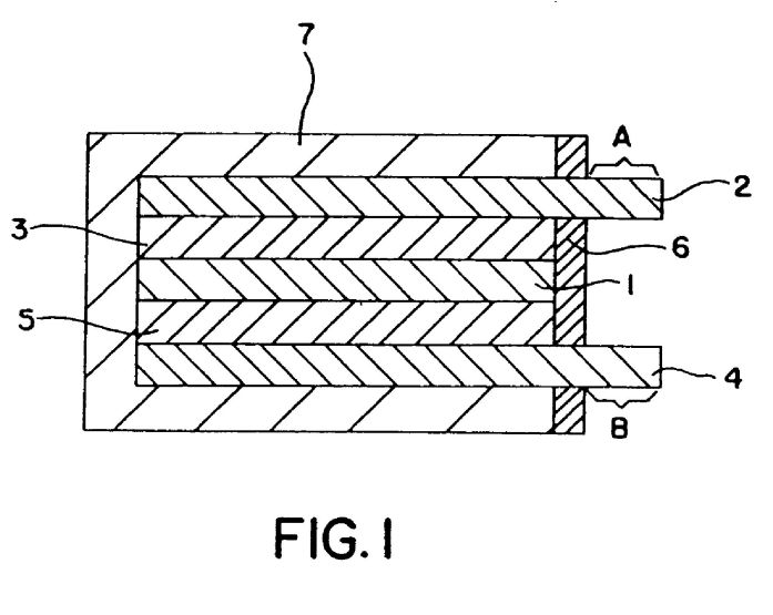
[0028] FIG. 2 depicts a plan view of a positive electrode terminal film doubling as a positive electrode collector made of aluminum;

[0029] FIG. 3 depicts a plan view of a negative electrode terminal film doubling as a negative electrode collector made of copper; and

[0030] FIG. 4 depicts a porous microstructure having additives and polymer electrolyte.

[0031] An important feature of the invention is the functional material b). By "functional" is meant that the material has some feature which affects the properties and function of the composites.
[0032] The Microporous Sheet
[0033] Suitable microporous polymer films include those made from polyolefins, polyamides, polycarbonates, cellulosics, polyurethanes, polyesters, polyethers, polyacrylates, copolyether esters, copolyether amides, chitosan, and fluoropolymers. Suitable fluoropolymers include membranes of porous polytetrafluoroethylene, more preferably a membrane of expanded porous PTFE (sometimes referred to as ePTFE) produced by the process taught in U.S. Pat. No. 3,953,566 (to Gore).
[0034] Porous polytetrafluoroethylene sheet or film suitable for use in the invention can be made by processes known in the art, for example, by stretching or drawing processes, by papermaking processes, by processes in which filler materials are incorporated with the PTFE resin which are subsequently removed to leave a porous structure, or by powder sintering processes. Preferably the porous polytetrafluoroethylene film is porous expanded polytetrafluoroethylene film having a structure of interconnected nodes and fibrils, as described in U.S. Pat. Nos. 3,953,566 and 4,187,390 which describe the preferred material and processes for making them. The nodes and fibrils define an internal structure having a three-dimensional network of interconnected passages and pathways which extend vertically, from surface to surface, and laterally, from edge to edge, throughout the membrane. The porous polytetrafluoroethylene membrane should have a thickness in the range 3 to 1,000 micrometers, preferably in the range 5 to 100 micrometers; a pore volume in the range 20 to 98 percent, preferably in the range 50 to 90 percent; and a nominal pore size in the range 0.05 to 15 micrometers, preferably in the range 0.1 to 2 micrometers.
[0035] Microporous films of other polymers such as thermoplastic polymers are described in U.S. Pat. No. 4,539,256 to Sherman, incorporated herein by reference. Preparation of microporous polyurethanes is described in U.S. Pat. No. 4,429,000. Preparation of microporous polymeric films, especially microporous polyolefins (polyethylene, polypropylene, polybutenes, polypentenes, etc.) is described in British Patent 1339207. Preparation of microporous films by stretching is described in U.S. Pat. No. 4,726,989 where use of polyamides, polyolefins, polystyrenes, polyvinylidene fluoride, and polycaprolactanes are described. Preparation of microporous films by liquid extraction is described in U.K. Publication No. GB 2,026,381. Stretching is described in U.S. Pat. No. 4,100,238. Preparation by film fracture, hot stretching is described in U.S. Pat. No. 3,679,540. All these patents are incorporated by reference for their description of the polymers.
[0036] GB 2,026,381 discloses the preparation of membranes having a porous surface by blending polymer with a liquid component to form a binary two-phase system which, in the liquid aggregate state, has a region of miscibility and a region with miscibility gaps, forming a sheet of the blend, casting the film into a bath of the liquid component and removing the liquid component to provide porosity. The resultant non-oriented porous sheet has a relatively low tensile strength.
[0037] U.S. Pat. Nos. 3,953,566, 3,962,153, 4,096,227, 4,110,392, 4,187,390 and 4,194,041, all incorporated by reference, describe the preparations of porous articles, including microporous sheets, formed of polytetrafluoroethylene (PTFE), a non-thermoplastic polymer, which is characterized by having a microstructure of nodes connected by fibrils. Such articles are produced by extruding a paste comprised of PTFE particles and a lubricant, removing the lubricant and stretching and annealing the resultant product. The resultant product is a sintered, oriented porous film of PTFE.
[0038] U.S. Pat. Nos. 4,100,238 and 4,197,148, incorporated by reference, describe the preparation of microporous films by extruding a two component blend, solvent leaching one dispersed component and stretching the resultant leached film to obtain a desired porosity. The blend consists of polymer and a leachable, non-miscible substance. Once the leachable dispersed polymer phase is removed and the film oriented, a porous film results.
[0039] U.S. Pat. No. 3,679,540, incorporated by reference, discloses a method for making a microporous polymer film by cold stretching an elastic polymer film until porous surface regions are formed by film failure hot stretching the cold stretched film until fibrils and pores or open cells are formed and then heat setting the resultant film. Controlled porosity is generally not attained in such films because they do not always uniformly fibrillate to a specific pore size.
[0040] Certain U.S. patents disclose the preparation of porous polymer film by blending into the polymer non-miscible leachable particulate substance such as starch, salts, etc., forming a sheet and leaching the particulate substance from the polymer sheet. Such U.S. patents, incorporated by reference, include: U.S. Pat. Nos. 3,214,501 and 3,640,829, U.S. Pat. No. 3,870,593 discloses the preparation of a microporous polymer sheet by blending non-miscible, non-leachable filler into the polymer, forming a sheet of the blend and stretching the sheet to form pores which are initiated at the sites of the filler particles.
[0041] U.S. Pat. No. 4,539,256 which patent is hereby incorporated by reference, teaches a method of making a microporous sheet which comprises the steps of melt blending a crystallizable thermoplastic polymer with a compound which is miscible with the thermoplastic polymer at the polymer melting temperature but immiscible on cooling below the polymer melting temperature, forming a sheet of the melt blend, cooling the sheet to a temperature at which the compound becomes immiscible with the polymer to cause phase separation between the thermoplastic polymer and the compound to provide a sheet.
[0042] Such porous polymer films or sheets will preferably have a porosity of greater than 35%. More preferably, the porosity should be between 40-95% preferably 70%. The thickness of the film is preferably less than 2 mil (0.05 mm, 50 micrometers). Preferably the thickness is between 0.06 mils (1.5 m) and 1.6 mils, and most preferably the thickness is between 0.50 mils (0.013 mm) and 1.50 mils (0.038 mm).
[0043] A preferred film is expanded porous PTFE commercially available in a variety of forms from W. L. Gore & Associates, Inc., under the trademark GORE-TEX membrane. The porous microstructure of such expanded porous PTFE films either comprises nodes interconnected by fibrils, or comprises substantially fibrils with substantially no nodes present. Preferred porous expanded PTFE films can be characterized as having a bubble point between 10 and 60 psi; and an air flow between 20 Frazier and 10 Gurley seconds. It may also have a pore size distribution value between 1.05 and 1.20; and a ball burst strength between 0.9 and 17 pounds/force.
[0044] The Functional Material
[0045] The material covering the structure defining the pores can be a metal oxide. The metal oxides endow the composite with improved mechanical strength sustainable over a long period of time ePTFE has good inherent mechanical strength, but this mechanical strength must be further enhanced by the metal oxide.
[0046] The metal oxide also acts as a matrix to stably retain the solid polymer electrolyte in the pores at a high content. Because of its high porosity, the ePTFE is capable of accepting and holding large amounts of solid polymer electrolytes. In addition, the solid polymer electrolyte that fills the pores cannot be desorbed easily because it is retained by th fine fibrils and minute nodes of ePTFE. Furthermore, the oxides, improve the wettability of the microporous sheet, making it easier for the solid polymer electrolyte to pack the pores.
[0047] In addition, the metal oxide is stable at elevated temperatures. The performance of lithium cells and other electrochemical reaction apparatuses is gradually improving, and it is believed that heating is caused by the repeated charging and discharging occurring at a high current density, by short circuits, and by other undesirable phenomena. If the solid polymer electrolyte lacks heat resistance or is incapable of preserving its shape at high temperatures, the functions are lost and an extensive short circuit occurs, creating the danger of a malfunction. A composite acts to prevent a short circuit from forming between electrodes.
[0048] In the present invention, an expanded porous polytetrafluoroethylene which has continuous pores and in which the inner surfaces of the pores are covered with a metal oxide is used in order to retain the aforementioned solid polymer electrolyte. Examples of the metal oxides used in this case include oxides of the following elements: lithium, beryllium, boron, sodium, magnesium, aluminum, Ai [sic], phosphorus, potassium, calcium, cerium, titanium, vanadium, chromium, manganese, iron, cobalt, nickel, copper, zinc, gallium, germanium, selenium, rubidium, strontium, yttrium, zirconium, niobium, molybdenum, ruthenium, rhodium, palladium, cadmium, indium, tin, antimony, tellurium, cesium, barium, lanthanum, cerium, praseodymium, neodymium, samarium, europium, cadmium, terbium, dysprosium, holmium, erbium, thulium, ytterbium, lutetium, thorium, protactinium, hafnium, tantalum, tungsten, platinum, titanium, lead, bismuth, and the like.
[0049] Functional additives can be, for example, an inorganic filler, or a catalyst or a combination of such materials. Examples include, but are not limited to, silica, platinum, titanium dioxide, platinum supported on silica, platinum supported on titania, carbon, boron nitride, barium titanate, or a blend of materials, or a polymer such as a fluorocarbon, or a polyolefin, etc.-different to the original microporous substrate and the ion exchange material utilized such as for example perflouro sulfonic acid resin.
[0050] One application is an improved self humidified membrane for a PEM fuel cell where the filler is silica or titanium dioxide which serves to aid in the back migration of product water from the cathode to the anode.
[0051] A second application is a self humidified low gas cross over PEM fuel cell membrane where the filler is platinum, or platinum supported on silica or titania, which serves to react and produce water in the membrane from any reactant which might otherwise diffuse through the membrane and degrade open circuit performance.
[0052] A third application is where the filler is boron nitride which serves to aid in heat conduction through the membrane.
[0053] A fourth application is a super capacitor where the filler is boron titanate which serves to increase the dielectric capability of the membrane.
[0054] A fifth application is where the filler is electrically conductive and serves to transport electrons through the membrane as well as protons for the production of H2O2 in a shorted fuel cell arrangement. This allows a much simpler cell design since it is no longer necessary to provide an external path for the electrons to flow.
[0055] A sixth application is where the filler is an ion exchange material which serves to improve the bond between the support and an ion exchange material in the polymer electrolyte.
[0056] A seventh application is where the filler is a material which lowers the surface energy of the substrate thus improving or allowing wetting and easier processing of ion exchange material into the microporous structure.
[0057] The Polymeric Electrolyte
[0058] (1) Polymer Compositions that Contain Metal Salts.
[0059] Examples of polymer compositions include polyethers, polyesters, polyimides, cross-linked polyethers, polymers containing polyether segments, polymers of vinyl silane having alkoxy groups, polymethyl
siloxanes having ethylene oxy (EO) groups, polyphosphazenes having EO groups, polymethacrylic acid esters having EO groups, polyacrylic acid, polyaziridine, polyethylene sulfide, and other polar polymer substances. Examples of electrolytes in the polymers include various metal salts such as LiCIO4, LiCF3SO3, LiF, Nal, Lil, NaSCN, LiBF4, LiPF6, LiBPh4 (Ph: phenyl group), and other alkali metal salts, as well as sulfuric acid, phosphoric acid, trifluoromethanesulfonic acid, tetrafluoroethylenesulfonic acid, and other proton acids.
[0060] (2) Polymeric Gels that Include Electrolytes.
[0061] These polymers absorb and gel an electrolyte. Examples of such electrolyte solutions include solutions obtained by dissolving electrolytes and other necessary soluble polymers in organic solvents such as propylene carbonate, [delta]-butyrolactone, dimethoxyethane, dioxane, tetrahydrofuran, acetonitrile, dimethyl sulfoxide, methyl tetrahydrofuran, and sulfolane. The polymers are not subject to any particular limitations as long as they are polymers that have cross-linked structures and are capable of absorbing and gelling the aforementioned electrolyte solutions, and any of the various conventionally known products can be used.
[0062] (3) Ion-Exchange Resins
[0063] The ion-exchange polymeric materials used can be any ion-exchange materials that will provide the desired result. The materials are preferably fluorinated because the material should be substantially inert to chemical activity and should be heat resistant.
[0064] The ion-exchange polymeric material will of course contain ionic functionality, preferably sulfonic moieties, carboxylic moieties or phosphonic moieties. The functional groups are present in an amount sufficient to impart ion-exchange properties to the polymer. An equivalent weight too high results in the electrical resistivity being too high. But if the equivalent weight is too low, mechanical strength becomes poor. The ionic functionality will usually be provided by carboxylic, sulfonic or phosphonic groups present either on the polymer backbone or present on pendant groups that extend from the polymer backbone in a recurring fashion. The polymer backbone will preferably be a fluorinated hydrocarbon backbone chain. The functional group preferably will have the structure -COOM, -SO3M or PO3M2, where M is hydrogen, a metallic cation or NH+4. If a metallic cation, it will preferably be an alkali metal or an alkaline earth metal, such as Na+, K+ or the like.
[0065] For carboxylic functionality, the pendant side chains which carry the above functional groups may have at the terminal end of the side chain a group of the formula:
EMI1.0
[0066] where V is -COOM, Z is -F or -CF3 and [tau] is an integer of 1-12, preferably 1 or 2, as described in U.S. Pat. No. 4,437,951 to DuPont, all of which is incorporated by reference for its disclosure of both carboxylic and sulfonic functionality.
[0067] The sulfonyl polymers with which the present invention is concerned are typically polymers having a fluorinated hydrocarbon backbone chain to which are attached the sulfonic containing functional groups as pendant side chains. For sulfonic polymers, terminal portion of the side chains can be:
[0068] -CFRSO3M,
[0069] -CF2CFRSO3M, or
[0070] -OCF2CF2-SO3M, or the like
[0071] where R is F, Cl, or perfluoroalkyl and M is as described earlier.
[0072] For phosphoric polymers, the same sort of pendant groups are present.
[0073] Other ion-exchange resins useful herein, in addition to the fluorinated carboxylic resins and the fluorinated sulphonic and phosphoric resins described above, include, but are not limited to, polyvinyl alcohol (PVA), divinyl benzene/styrene copolymers, provided they have the requisite functional groups pendant chains. The polymers can be mixed with a metal salt to obtain the desired functionality. A sulfonated polymer of trifluorostyrene, such as homopolymer or a copolymer with tetrafluoroethylene, can be used.
[0074] It is understood that the foregoing description of ion-exchange resins is not limited and is representative. It is understood that the invention can employ any polymer type of ion-exchange material. Thus, as seen above, not only do the resins include ones with the functional group as a part of the polymer, but also ones where the functional groups are provided by an additive to the polymer.
[0075] The ion-exchange resins used in the invention can be prepared by general polymerization techniques developed for homo and copolymerizations of fluorinated ethylenes, particularly those employed for tetrafluoroethylene which are described in the literature. Nonaqueous techniques for preparing the copolymers include that of U.S. Pat. No. 3,041,317, that is, by the polymerization of a mixture of the major monomer therein, such as tetrafluoroethylene, and a fluorinated ethylene containing a sulfonyl fluoride group in the presence of a free radical initiator, preferably a perfluorocarbon peroxide or azo compound, at a temperature in the range 0-200[deg.] C. and at pressures in the range of 105 to 2*107 Pascals (1-200 Atm.) or higher. The nonaqueous polymerization may, if desired, be carried out in the presence of a fluorinated solvent. Suitable fluorinated solvents are inert, liquid, perfluorinated hydrocarbons, such as perfluoromethylcyclohexane, perfluorodimethylcyclobutane, perfluorooctane, perluorobenzene and the like, and inert, liquid chloro-fluorocarbons such as 1,1,2-trichloro-1,2-2-trifluoroethane, and the like. Aqueous techniques for preparing such copolymers include contacting the monomers with an aqueous medium containing a free-radical initiator to obtain a slurry of polymer particles in non-water-wet or granular form, as disclosed in U.S. Pat. No. 2,393,967, or contacting the monomers with an aqueous medium containing both a free-radical initiator and a telogenically inactive dispersing agent, to obtain an aqueous colloidal dispersion of polymer particles, and coagulating the dispersion, as disclosed, for example, in U.S. Pat. No. 2,559,752 and U.S. Pat. No. 2,593,583.
[0076] In addition, ion-exchange polymer resins described and prepared as in U.S. Pat. No. 4,267,364 to DuPont; U.S. Pat. No. 4,544,458 to DuPont; U.S. Pat. No. 4,178,218 to Asahi; U.S. Pat. No. 4,255,523 to Asahi; U.S. Pat. No. 5,082,472 to Mallouk, et al.; and U.S. Pat. No. 5,422,411 to Wei, et al., all incorporated by reference, can be used.
[0077] Other examples of ion exchange materials include, such as polyvinyl alcohol, divinyl benzene, styrene based polymers, alpha beta triflurostyrene, or a ketone based ionomer such as sulfonated polyetherketone ether ketone (PEKEK) and metal salts with or without a polymer. The ion exchange material may also be comprised of at least in part a powder such as but not limited to carbon black, graphite, nickel, silica, titanium dioxide, platinum, boron nitrate, barium titanate or a non-ionic polymer such as poyvinylidene fluoride or a co-polymer of TFE, etc.
[0078] Preparation where Metal Oxide is the Functional Material.
[0079] An ePTFE in which the inner surfaces of the pores are covered with a metal oxide can be manufactured by a method comprising the following steps: a step in which the ePTFE is impregnated with a gelation product in the form of a solution obtained by allowing water to react with a hydrolyzable metal-containing organic compound, a step in which the gelation product in the form of a solution absorbed by the pores is allowed to react with water and converted to a gelation product in the form of a solid, and a step in which the gelation product in the form of a solid thus formed is heated and dried.
[0080] A metal alkoxide or metal complex is formed as the aforementioned hydrolyzable metal-containing organic compound (also referred to as the "metal oxide precursor").
[0081] Specific examples of metal alkoxides include tetramethoxytitanium, tetraethoxytitanium, tetraisopropoxytitanium, tetrabutoxytitanium, zirconium isopropylate, zirconium butyrate, tetramethoxysilane, tetraethoxysilane, tetraisopropoxysilane, and tetra-t-butoxysilane. Specific examples of metal complexes include titanium tetraacetyl acetonate, zirconium acetylacetonate, and other metal acetylacetonates. In the present invention, a silicone-based alkoxide such as tetraethoxysilane is particularly suitable for use.
[0082] The aforementioned metal oxide precursor is brought into contact with water, partially gelled, and made into a gelation product in the form of a solution before being complexed with the ePTFE. The gelation reaction can be a reaction well-known in the past, including a hydrolysis/polycondensation reaction.
[0083] Water can be added to the metal oxide precursor, and agitation and mixing can be performed, in order to partially gel the metal oxide precursor. A water-miscible organic solvent such as methanol, ethanol, propanol, butanol, or another alcohol can be added to the water in this case, and an acid (hydrochloric acid, sulfuric acid, nitric acid, acetic acid, hydrofluoric acid, or the like) or a base (sodium hydroxide, potassium hydroxide, ammonia, or the like) can also be added as needed. The partial gelation reaction of the metal oxide precursor can also be performed by adding water to the solution of the metal oxide precursor in an organic solvent, and agitating and mixing the system. In this case, any solvent can be used as the organic solvent as long as it is capable of dissolving the metal oxide. Aliphatic and aromatic hydrocarbons can be used in addition to alcohols. The gelation reaction is performed at a temperature that is generally 0 to 100[deg.] C. and preferably 60 to 80[deg.] C.
[0084] The proportion in which water is used should be 0.1 to 100 mol, and preferably 1 to 10 mol, per mole of the metal oxide precursor. Although it is preferable for the gelation reaction to be performed in a sealed system or in a flow of inert gas, it is also possible to promote the gelation reaction by the moisture contained in the outside air.
[0085] A partially gelled product in the form of a solution of the metal oxide precursor is thus obtained. As used herein, the term "partially gelled product of a metal oxide precursor" refers to a product used under conditions corresponding to the use of a metal oxide hydrous gel in the form of a solid that is a completely gelled product and that lacks fluidity.
[0086] To allow the partially gelled product of a metal oxide precursor to form a complex with the microporous sheet, it is possible to adopt a method in which the sheet is immersed in the partially gelled product in the form of a solution or a method in which the partially gelled product in the form of a solution is applied to the sheet with a spray or a roll, and any method can be used as long as it allows the partially gelled product to fill the pores of the surface portion and the interior of the sheet.
[0087] The sheet that has been complexed with the partially gelled product of a metal oxide precursor in such a manner is brought into contact with an excess amount of contained water in order to further promote the gelation reaction of the metal oxide precursor and to form a metal oxide hydrous gel in the form of a solid (completely gelled product). It is preferable for a method in which the sheet complexed with the partially gelled product of a metal oxide precursor is immersed in water to be used for such complete gelation, but it is also possible to use methods in which sprayed water is blown, steam is blown, or the like. In this case, the water used may contain acids or alkalis because it is used to promote the gelation reaction. A metal oxide hydrous gel is produced in th form of a film on the inner surfaces of the pores of the molding after the gelation reaction has been completed, and a monolithically deposited metal oxide forming a thin, uniform layer on the inner surfaces of the pores can be obtained by drying the gel at 300[deg.] C. or lower, and preferably 200[deg.] C. or lower. The thickness of the metal oxide layer is 0.01 to 0.2 [mu]m, and preferably 0.02 to 0.1 [mu]m. Because it is formed from a metal oxide hydrous gel obtained in such a manner, the metal oxide forms a monolithic, continuous film and has excellent adhesion that impairs its separation from the porous body. The metal oxide composite molding has a high void volume, which is at least 50%, and preferably at least 70%, of the void volume of the initial molding.
[0088] Alternatively, the functional material can be introduced into the micropores of the polymeric sheet by imbibing the material into the pores and then heating to remove the imbibing solvent. When the microporous polymeric sheet is polytetrafluoroethylene (PTFE), the functional material can be added by mixing a particulate filler with a PTFE aqueous dispersion; cocoagulating the filler and the PTFE; lubricating the filled PTFE with lubricant; paste extruding and optionally calendering to form a film; and expanding the film by stretching it so as to form a porous PTFE membrane having the filler distributed therein.
[0089] Alternatively, the microporous ePTFE can be plated with a metal described in U.S. Pat. No. 4,720,400 (Manniso).
[0090] Alternatively, a microporous article such as catalyst filled ePTFE described in part by U.S. Pat. No. 5,602,669 may be used as the substrate.
[0091] The solid polymer electrolyte can be placed into the pores by roll application, spraying, dipping, or another technique with a solution or dispersion containing the solid polymer electrolyte, and the solvent is then removed. The pores can be filled with a polymerization solution comprising an electrolyte and a monomer, and the ingredients polymerized inside the pores. The pores can be filled with a polymerization solution comprising an electrolyte, a monomer, and a solvent, the ingredients polymerized inside the pores, and the solvent is subsequently removed. The pores can be filled with an electrolyte-containing partially gelled solution of a polymer, and the ingredients are gelled inside the pores. Specific methods for introducing a solid polymer electrolyte into the pores of a molding are appropriately selected in accordance with the type of solid polymer electrolyte.
[0092] The pores can be either partially or fully imbibed with ion exchange medium such as an ionomer in an alcohol solution such as is commercially available from Ashai Glass such as Flemion(R) solution in ethanol. The ion exchange medium may subsequently be dried or re-dissolved as the case may require.
[0093] A product of the invention is depicted in FIG. 4. A composite membrane 10 is provided which is made up of a microporous polymeric sheet comprised of nodes 11 and fibrils 12. In some embodiments, the sheet can be comprised of only fibrils. The nodes and fibrils are covered, at least in part by functional material 13. The space between the nodes and fibrils is then filled, preferably, completely (i.e., no air flow through) with the polymer electrolyte. Preferably the interior volume of the sheet is substantially occluded by the electrolyte.
[0094] The composite membranes of the present invention may be employed in various applications, including but not limited to polarity based chemical separations, electrolysis, fuel cells, batteries, pervaporation, gas separation, dialysis, industrial electrochemistry, super acid catalyst, medium for enzyme immobilization and the like.
[0095] Examples of use in some electrochemical applications include lithium primary cells, magnesium cells, and other primary cells, lithum secondary cells; polymer cells and other secondary cells; and fuel cells.
EXAMPLE 1
[0096] 100 parts of tetraethoxysilane (manufactured by Sinetsu Silicone), 52 parts of water, and 133 parts of ethanol were allowed to react for 24 hours at 80[deg.] C. under reflux conditions in which the supply of moisture contained in the outside air was shut off with the aid of a calcium chloride tube, yielding a partially gelated solution of a metal oxide precursor. An expanded porous polytetrafluoroethylene film (manufactured by Japan Gore-Tex Inc.; thickness: 25 [mu]m; pore diameter: 0.5 [mu]m; thickness: 40 [mu]m; porosity: 92%) was impregnated with this solution and immersed in warm water (60[deg.] C.) for 5 hours to complete the gelation. The gelled product was dried for 30 minutes at 150[deg.] C., yielding a silica gel complex extended porous polytetrafluoroethylen film in which the exposed surfaces, including the inner surfaces, of the porous body were covered with the silica gel. This composite film retained at least 80% of the voids of the original porous film and was highly porous.
[0097] An acrylonitrile-methacrylate copolymer powder obtained from Japan Exlan Co. Ltd (molar ratio: 90/10) was subsequently added at a rate of 1.5 g/10 ml, and acetonitrile was added at the same time at a rate of 1.5 g/10 ml, to an organic electrolyte solution obtained by dissolving LiPF6, an electrolyte liquid mixed with propylenecarbonate and ethyl carbonate obtained from Tomiyama Pure Chemical Industry, in a mixed solvent (organic solvent) of propylene carbonate and ethylene carbonate (volume ratio: 1/1) in such a way that the concentration was 1 M, yielding an acetonitrile-diluted polymeric gel molecule/electrolyte mixture.
[0098] The acetonitrile-diluted polymer gel/electrolyte mixture was subsequently absorbed by the pores (cavities) of the aforementioned silica gel composite extended porous polytetrafluoroethylene film, then vacuum-dried for at least 5 hours at 60[deg.] C. to remove the acetonitrile, and finally cooled to -20[deg.] C., yielding a solid polymer electrolyte composite with a thickness of about 25 [mu]m.
[0099] The ionic conductivity (20[deg.] C.; complex impedance technique) and the tensile strength as tested by JIS K 7113, of this polymer solid electrolyte composite were measured. The results are shown in Table 1.
COMPARATIVE EXAMPLE 1
[0100] An acetonitrile-diluted polymeric gel/electrolyte mixture prepared in the same manner as in Example 1 was cast, yielding a solid polymer electrolyte (simple substance) with a thickness of 25 [mu]m. In this case, the simple solid polymer electrolyte had insufficient mechanical strength, was difficult to handle, and was impractical as a film.
[0101] For the sake of comparison, a solid polymer electrolyte film (simple substance) composed of a polymer/electrolyte with a thickness of 100 [mu]m was fabricated, and the ionic conductivity (20[deg.] C.; complex impedance technique) and tensile strength of the film were measured. The results are shown in Table 1.
[0102] It follows from Table 1 that the solid polymer electrolyte composite of the present invention is a solid polymer electrolyte in which the mechanical strength is significantly improved while the ionic conductivity is maintained at the level of a conventional solid polymer electrolyte. The composite of the present invention can be easily made into a thin film and stably fabricated into a solid polymer electrolyte film of about 25 [mu]m, making it possible to reduce the resistance of the solid polymer electrolyte portion.
TABLE 1
Comparative
Item Example 1 Example
Ionic conductivity 1.5 * 10<-3> 1.5 * 10<-3>
(S/cm<2>)
Tensile strength 150 8
(kg/cm<2>)
EXAMPLE 2
[0103] A lithium secondary cell will now be described as an embodiment example of an electrochemical reaction apparatus obtained using the aforementioned solid polymer electrolyte composite.
[0104] FIG. 1 is a structural cross-sectional diagram of the lithium secondary cell of the present invention. In FIG. 1, 1 is the solid polymer electrolyte composite film pertaining to the present invention; 2 is a positive electrode terminal film doubling as a positive electrode collector made of aluminum; 3 is a positive electrode film consisting of LiCoO2 (obtained from Nippon Chemical Ind.), acetylene black (obtained from Denki Kagaku as Denka Black), and a polymeric gel/electrolyte mixture (corresponds to a product obtained by removing acetonitrile from the aforementioned acetonitrile solution); 4 is a negative electrode terminal film doubling as a negative electrode collector made of copper; 5 is a negative electrode film consisting of graphite and a polymeric gel/electrolyte mixture (corresponds to a product obtained by removing acetonitrile from the aforementioned acetonitrile solution); 6 is a seal; and 7 is a casing. FIG. 2 is a plan view of the positive electrode terminal film doubling as a positive electrode collector made of aluminum. In FIG. 2, A is a positive electrode terminal, and B is a positive electrode collector.
[0105] FIG. 3 is a plan view of the negative electrode terminal film doubling as a negative electrode collector made of copper. In FIG. 3, C is a negative electrode terminal, and D is a negative electrode collector.
[0106] The method for manufacturing the aforementioned cell will now be described.
[0107] (1) Manufacture of Laminate L of Positive Electrode Film and Positive Electrode Terminal Film Doubling as Positive Electrode Collector Made of Aluminum
[0108] 15 g of an acrylonitrile-methacrylate copolymer powder (molar ratio: 90/10) and 12 g of acetonitrile were simultaneously added to 100 ml of an organic electrolyte solution obtained by dissolving LiPF6 in a mixed solvent (organic solvent) of propylene carbonate and ethylene carbonate (volume ratio: 1/1) in such a way that the concentration was 1M, yielding an acetonitrile-diluted polymer gel/electrolyte mixture.
[0109] 4 g of an LiCoO2 powder with a mean grain diameter of about 20 [mu]m and 0.2 g of acetylene black were subsequently added to 7.3 g of the aforementioned acetonitrile-diluted polymer gel/electrolyte mixture, and the ingredients were uniformly agitated, yielding a starting solution for the positive electrode. This starting solution was spread over the entire surface (with the exception of the terminal A) of the flat aluminum positive electrode collector 2 (thickness: 20 [mu]m) shown in FIG. 2, the collector was vacuum-dried for over 5 hours at 60[deg.] C. to remove the acetonitrile, and the dried collector was cooled to -20[deg.] C.
[0110] A laminate L of the positive electrode film 3 and the positive electrode terminal film 2 doubling as a positive electrode collector made of aluminum was thus obtained. In this laminate L, the terminal (A in FIG. 2) measured 1 cm*2 cm and had a thickness of 20 [mu]m, and the positive electrode collector (B in FIG. 2) measured 5.8 cm*5.8 cm and had a thickness of 220 [mu]m.
[0111] (2) Manufacture of Laminate M of Negative Electrode Film and Negative Electrode Terminal Film Doubling as Negative Electrode Collector Mad of Copper
[0112] 4 g of a partially graphitized carbon material (obtained from Kureha Chemical Co. Ltd) with a mean grain diameter of about 10 [mu]m was added to 7.3 g of the aforementioned acetonitrile-diluted polymer gel/electrolyte mixture, and the ingredients were uniformly agitated, yielding a starting solution for the negative electrode. This starting solution was spread over the entire surface (with the exception of the terminal C) of the flat copper negative electrode collector 4 (thickness: 20 [mu]m) shown in FIG. 3, the collector was vacuum-dried for over 5 hours at 60[deg.] C. to remove the acetonitrile, and the dried collector was cooled to -20[deg.] C.
[0113] A laminate M of the negative electrode film 5 and the negative electrode terminal film 4 doubling as a negative electrode collector made of copper was thus obtained. In this laminate M, the terminal (C in FIG. 3) measured 1 cm*2 cm and had a thickness of 20 [mu]m, and the negative electrode collector (D in FIG. 3) measured 5.8 cm*5.8 cm and had a thickness of 520 [mu]m.
[0114] (3) Manufacture of Solid Polymer Electrolyte Composite Film
[0115] A film 1 measuring 5.8 cm*5.8 cm was manufactured from the solid polymer electrolyte composite film (thickness: 25 [mu]m) of Practical Example 1.
[0116] (4) Cell Manufacture
[0117] The aforementioned laminate L was superposed on one side of the solid polymer electrolyte composite film 1, the aforementioned laminate M was superposed on the other side, and the resulting assembly was kept at a pressure of 1 kg/cm2 for 1 minute, yielding a laminate.
[0118] The laminate was subsequently introduced into a casing (7 in FIG. 1) that consisted of polypropylene, was open at one end, and had a thickness of 1 mm. The open end was sealed with polypropylene resin film, yielding a seal (6 in FIG. 1).
[0119] The lithium secondary cell thus obtained was subjected to charge/discharge cycle tests at a temperature of 20[deg.] C., an upper limit of 4.3 V, and a lower limit of 3.0 V, with the discharge being conducted at a constant current of 8 mA. The results are shown in Table 2.
COMPARATIVE EXAMPLE 2
[0120] A lithium secondary cell was manufactured using, as an electrolyte film, the solid polymer electrolyte (simple substance; thickness: 25 [mu]m) of Comparative Example 1 instead of the solid polymer electrolyte composite film in Practical Example 2, but the components were difficult to handle and could not be made into a cell.
[0121] In view of this, a lithium secondary cell was fabricated in the same manner as in Practical Example 2 except that the solid polymer electrolyte film (simple substance; thickness: 100 [mu]m) of Comparative Example 1 was used instead of the solid polymer electrolyte composite film.
[0122] The resulting cell was subjected to charge/discharge cycle tests at a temperature of 20[deg.] C., an upper limit of 4.3 V, and a lower limit of 3.0 V, with the discharge being conducted at a constant current of 8 mA. The results are shown in Table 2.
[0123] It can be seen in Table 2 that the lithium secondary cell of the present invention remains stable over a large number of cycles and that the cell capacity deteriorates only slightly even when the number of cycles exceeds 200.
[0124] By contrast, the lithium secondary cell of Comparative Example 2 is configured in such a way that the solid polymer electrolyte portion (simple substance) of the cell is four times thicker than the corresponding portion of the cell obtained in Practical Example 2, quadrupling the resistance of the solid polymer electrolyte portion (simple substance). As a result, the capacity deteriorates only slightly even when the number of cycles exceeds 200, but the discharge capacity is low. These results indicate that the present invention allows a compact, high-performance cell to be obtained.
TABLE 2
Number of Discharge capacity (mAh)
charge/ Product of present Comparison
discharge cycles invention product
1 46.5 40.0
50 56.3 43.2
100 56.2 43.1
150 56.2 42.9
200 56.1 42.8
250 56.0 42.7
EXAMPLE 3
[0125] A multi-functional membrane was made by
[0126] a) mixing a particulate filler with PTFE aqueous dispersion,
[0127] b) cocoagulating the filler and the PTFE
[0128] c) lubricating the filled PTFE with lubricant
[0129] d) paste extruding and optionally calendering to form a film
[0130] e) expanding said film by stretching it so as to form a porous PTFE having said filler distributed therein.
[0131] An aqueous dispersion of PTFE resin (20-36% solids) was obtained. Into the aqueous dispersion, particulate filler of Fumed Silica, Cabosil(R) M5, from Cabot Corp. was added to produce a 20% by weight silica final dried mixture. This mixture was cocoagulated by rapid shearing of the aqueous dispersion. A coagulum of fine powder PTFE resin and silica filler was subsequently formed and dried into cakes. When dry, the cakes were carefully crumbled and lubricated with an odorless mineral spirit. The amount of mineral spirits used was 0.52 grams per gram of PTFE/SiO2 dry powder.
[0132] This mixture was aged below room temperature to allow for the mineral spirits to become uniformly distributed within the PTFE/SiO2 powder resin. This mixture was compressed into a billet and extruded at 1200 psi through a 0.045 inch by 6 inch gap die attached to a ram type extruder to form a coherent extrudate. A reduction ratio of 44:1 was used.
[0133] Two layers of extrudate were stacked together to form 100 mil assembly and subsequently rolled down between two metal rolls which were heated to between 50[deg.] C. The final thickness after roll down was 0.014 inch. The material was transv rsely xpanded at a ratio of 3:1 and then the mineral spirits were removed from the xtrudate by heating the mass to 250[deg.] C. (i.e. a temperature wh re th mineral spirits were highly volatile). The dried extrudate was transversely expanded at 150[deg.] C. at a ratio of 3.5:1 and a rate of 2300% per second. After expansion the sheet was amorphously locked at greater than 340[deg.] C. and cooled to room temperature.
[0134] This membrane was subsequently imbibed with ion exchange resin solution as in example 5 to create a ion exchange composite membrane.
[0135] Electrodes loaded at 0.3 mg/cm<2 >platinum were attached to both sides of the membrane and the membrane electrode assembly was placed in a single cell fuel cell test apparatus.
[0136] Air and H2, both at 40 psig and 25[deg.] C., were fed to the cell. A steady state current of 1.178 amps/cm<2 >was produced at 0.5 volts with no humidification of the incoming reactants. Cell temperature was 50[deg.] C. A microreinforced membrane with no filler yielded only 0.975 amps at the same test conditions.
EXAMPLE 4
[0137] An aqueous dispersion of PTFE resin was obtained. Into the aqueous dispersion, a particulate carbon black (Ketjen Black) filler was added to produce a 20% by weight final dried mixture. This mixture was cocoagulated by rapid shearing of the aqueous dispersion. A coagulum of fine powder PTFE resin and carbon filler was subsequently formed and dried into cakes. When dry, the cakes were carefully crumbled and lubricated with an odorless mineral spirit. The amount of mineral spirits used was 0.20 grams per gram of PTFE/carbon black dry powder.
[0138] This mixture was compressed into a billet and extruded at 1500 psi through a 0.045 inch by 6 inch gap die attached to a ram type extruder to form a coherent extrudate. A reduction ratio of 84:1 was used.
[0139] The extrudate was then rolled down between two metal rolls which were heated to between 50[deg.] C. The final thickness after roll down was 0.010 inch. The mineral spirits were removed from the extrudate by heating the mass to 250[deg.] C. (i.e. a t mperature where the mineral spirits were highly volatile). The dried extrudate was transversely expanded at 150[deg.] C. at a ratio of 3.5:1. After expansion, the sheet was heated to amorphously locked at greater than 340[deg.] C. and cooled to room temperature.
[0140] This membrane was subsequently imbibed with Flemion(R) (Asahi Glass) ion exchange resin solution (9% by weight resin in ethanol) and dried 3 times.
[0141] The final composite thickness was 27 microns.
EXAMPLE 5
[0142] An aqueous dispersion of PTFE resin is obtained. Into the aqueous dispersion, a particulate titania filler was added to produce a 20% by weight final dried mixture. This mixture was cocoagulated by rapid shearing of the aqueous dispersion. A coagulum of fine powder PTFE resin and titania filler was subsequently formed and dried into cakes. When dry, the cakes were carefully crumbled and lubricated with an odorless mineral spirit. The amount of mineral spirits used was 0.20 grams per gram of PTFE/titania dry powder.
[0143] This mixture was compressed into a billet and extruded at 1500 psi through a 0.045 inch by 6 inch gap die attached to a ram type extruder to form a coherent extrudate. A reduction ratio of 84:1 was used.
[0144] The extrudate was then rolled down between two metal rolls which were heated to between 50[deg.] C. The final thickness after roll down was 0.008 inch. The mineral spirits were removed from the extrudate by heating the mass to 250[deg.] C. (i.e. a temperature where the mineral spirits were highly volatile). The dried extrudate was transversely expanded at 150[deg.] C. at a ratio of 3.5:1 and at a rate of 440% per second. After expansion, the sheet was amorphously locked at greater than 340[deg.] C. and cooled to room temperature.
[0145] It was subsequently imbibed with ion exchange media by brushing both sides with a solution of PFSA in ethanol (Flemion(R) 9% by weight).
EXAMPLE 6
[0146] An aqueous dispersion of PTFE resin was obtained. Into the aqueous dispersion, a platinum coated titania catalyst was added to produce a 10% by weight final dried mixture. This mixture was cocoagulated by rapid shearing of the aqueous dispersion. A coagulum of fine powder PTFE resin and catalyst filler was subsequently formed and dried into cakes. When dry, the cakes were carefully crumbled and lubricated with an odorless mineral spirit. The amount of mineral spirits used was 0.26 grams per gram of PTFE/catalyst dry powder.
[0147] This mixture was compressed into a billet and extruded at 3000 psi through a 0.045 inch by 6 inch gap die attached to a ram type extruder to form a coherent extrudate. A reduction ratio of 44:1 was used.
[0148] The extrudate was then rolled down between two metal rolls which were heated to 50[deg.] C. The final thickness after roll down was 0.016 inch. The mineral spirits were removed from the extrudate by heating the mass to 250[deg.] C. (i.e. a temperature where the mineral spirits were highly volatile).
[0149] A portion of this roll was then placed within a batch film expansion machine and expanded at an expansion rate of 500% per second to a ratio of 12:1 in both the machine and transverse direction.
[0150] This microporous membrane was subsequently imbibed with a fluorinated sulfonic acid resin composition as in example 5. The final thickness of the composite membrane was 15 microns. Electrodes with a total of 0.6 mg Pt/cm<2 >were attached and the membrane tested in a single cell fuel cell test apparatus. Air and H2, both at 40 PSIG and 25[deg.] C., were fed to the cell. A steady state current of 0.47 amps/cm<2 >was produced at 0.8 volts with no humidification of the incoming gasses. Cell temperature was 50[deg.] C. A 15 micron microreinforced membrane with no filler yielded only 0.36 amps at 0.8 volts under the same conditions.
Voltage for Voltage for
Current Example 5 Example 7
300 mA/cm<2> 0.835 0.810
600 mA/cm<2> 0.775 0.750
900 mA/cm<2> 0.705 0.670
[0151] While particular embodiments of the present invention have been illustrated and described herein, the present invention should not be limited to such illustrations and descriptions. It should be apparent that changes and modifications may be incorporated and embodied as part of the present invention within the scope of the following claims.