rexresearch.com

John C. BEDINI
Motor / Generator


John Bedini: US Patent # 6,392,370 ~ Device & Method of a Back-EMF Electromagnetic Motor Generator
J. Bedini: USP # 6,545,444 ~ Device and Method for Utilizing a Monopole Motor to Create Back-EMF to Charge Batteries
J. Bedini: USP Application # 20020097013 ~ Permanent Electromagnetic Motor Generator
J. Bedini: KeelyNet / Escribe BBS Comments
KeelyNet Forum
OtherPower.com Forum
Battery Test
PESWiki.com: "School Girl" Science Fair Bedini Motor Replication
Links
Images


John C. Bedini (1980s)


US Patent # 6,392,370

May 21, 2002 ~ US Cl. 318/140

Device and Method of a Back EMF Permanent Electromagnetic Motor Generator

John Bedini

Abstract --- This invention is a back EMF permanent electromagnetic motor generator and method using a regauging process for capturing available electromagnetic energy in the system. The device is comprised of a rotor with magnets of the same polarity; a timing wheel in apposition to a magnetic Hall Effect pickup switch semiconductor; and a stator comprised of two bars connected by a permanent magnet with magnetized pole pieces at one end of each bar. There are input and output coils created by wrapping each bar with a conducting material such as copper wire. Energy from the output coils is transferred to a recovery rectifier or diode. The magnets of the rotor, which is located on a shaft along with the timing wheel, are in apposition to the magnetized pole pieces of the two bars. The invention works through a process of regauging, that is, the flux fields created by the coils is collapsed because of a reversal of the magnetic field in the magnetized pole pieces thus allowing the capture of available back EMP energy. Additional available energy may be captured and used to re-energize the battery, and/or sent in another direction to be used as work. As an alternative, the available back EMF energy may be dissipated into the system.

Current U.S. Class: 318/140; 318/492; 318/538; 310/113
Intern'l Class:  H02K 047/14
Field of Search:  318/140,148,151,153,459,491,492,538 310/152,156,112,113

References Cited
U.S. Patent Documents:
2,560,260 ~ Jul., 1951 ~ Sturtevant, et al.
2,613,246 ~ Oct., 1952 ~ Spodig
2,974,981 ~ Mar., 1961 ~ Vervest, et al.
4,222,021 ~ Sep., 1980 ~ Bunker, Jr.
4,265,746 ~ May., 1981 ~ Zimmerman, Sr., et al.
4,265,754  ~ May., 1981 ~ Menold
4,417,167 ~ Nov., 1983 ~ Ishii, et al.
4,423,343 ~ Dec., 1983 ~ Field, II.
4,429,263 ~ Jan., 1984 ~ Miiller
4,433,260 ~ Feb., 1984 ~ Weisbord, et al.
4,488,075 ~ Dec., 1984 ~ DeCesare
RE31,950 ~ Jul., 1985 ~ Binns
4,536,230 ~ Aug., 1985 ~ Landa, et al.
4,761,590 ~ Aug., 1988 ~ Kaszman
4,916,346 ~ Apr., 1990 ~ Kliman
4,972,112 ~ Nov., 1990 ~ Kim
4,980,595 ~ Dec., 1990 ~ Arora
5,130,595 ~ Jul., 1992 ~ Arora
5,177,054 ~ Jan., 1993 ~ Lloyd, et al.
5,227,702 ~ Jul., 1993 ~ Nahirney
5,334,894 ~ Aug., 1994 ~ Nakagawa
5,350,958 ~ Sep., 1994 ~ Ohnishi
5,356,534 ~ Oct., 1994 ~ Zimmerman, et al.
5,369,325 ~ Nov., 1994 ~ Nagate, et al.
5,371,426 ~ Dec., 1994 ~ Nagate, et al.
5,451,825 ~ Sep., 1995 ~ Strohm
5,508,575 ~ Apr., 1996 ~ Elrod, Jr.
5,514,923 ~ May., 1996 ~ Gossler, et al.
5,528,113 ~ Jun., 1996 ~ Boys, et al. ~ 318/16.
5,532,532 ~ Jul., 1996 ~ DeVault, et al.
5,731,645 ~ Mar., 1998 ~ Clifton, et al. 310/74.
6,118,202 ~ Sep., 2000 ~ Pinkerton ~ 310/178.

Foreign Patent Documents:
0 462,340 Dec., 1991 EP.
0 932 248 Jul., 1999 EP.
2 224,398 May., 1990 GB.
WO 99/38,247 Jul., 1999 WO.

Description

BACKGROUND OF THE INVENTION

1. Field of the Invention

The invention relates generally to the capturing of electromagnetic energy using a method and device to create back EMF (electromagnetic force) and re-phasing of the back EMF to recycle and capture the available back EMF energy. Back EMF is also referred to as regauging and may be defined as energy created by the magnetic field from coils, and only by coils, and not by magnets.

2. Background Information and Related Art

Operation of a normal magnetic motor has the rotor pole attracting the stator pole, resulting in the generation of power from the magnets to the rotor and flywheel. During this phase, energy flows from the magnetics to the rotor/flywheel and is stored in the increased rotation. A rotor pole leaving a stator pole and creating a condition of drag-back results in power having to be put back into the magnetic section by the rotor and flywheel to forcibly overcome the drag-back. In a perfect, friction-free motor, the net force field is therefore referred to as most conservative. In other words, a most conservative EMF motor has maximum efficiency. Without extra energy continually fed to the motor, no net work can be done by the magnetic field, since half the time the magnetic field adds energy to the load (the rotor and flywheel) and the other half of the time it subtracts energy back from the load (the rotor and flywheel). Therefore the total net energy output is zero in any such rotary process without additional energy input. To use a present day magnetic motor, continuous energy must be input into the motor to overcome drag-back and to power the motor and its load.

Present EMF motors and generators all use such conservative fields and therefore, have internal losses. Hence, it is necessary to continually input all of the energy that the motor outputs to the load, plus more energy to cover losses inside the motor itself. EMF motors are rated for efficiency and performance by how much energy input into the motor actually results in output energy to the load. Normally, the Coefficient of Performance (COP) rating is used as a measure of efficiency. The COP is the actual output energy going into the load and powering it, divided by the energy that must be input into the device with its load. COP is the power out into the load, divided by the power input into the motor/load combination. If there were zero internal losses in a motor, that "perfect" motor would have a coefficient of performance (COP) equal to 1.0. That is, all energy input into the motor would be output by the motor directly into the load, and none of the input energy would be lost or dissipated in the motor itself.

In magnetic motor generators presently in use, however, due to friction and design flaws, there are always internal losses and inefficiencies. Some of the energy input into the motor is dissipated in these internal losses. As a consequence, the energy that gets to the load is always less than the input energy. So a standard motor operates with a COP of less than 1.0 which is expressed as COP<1.0. An inefficient motor may have a COP=0.4 or 0.45, while a specially designed, highly efficient motor may have a COP=0.85.

The conservative field inside of a motor itself can be divided into two phases. Producing a conservative field involves net symmetry between the "power out" phase from the magnetics to the rotor/flywheel and the "power back in" phase from the rotor/flywheel back to the magnetics. That is, the two flows of energy (one from the magnetics into the rotor and flywheel, and one from the rotor and flywheel back to the magnetics) are identical in magnitude but opposite in direction. Each phase alone is said to be "asymmetrical"; that is, it either has: 1) a net energy flow out to the rotor/flywheel; or 2) a net energy flow back into the magnetics from the rotor/flywheel. In simplified terms, it is referred to as "power out" and "power back in" phases with respect to the motor magnetics. Hence, the two asymmetrical phases are: 1) the power-out phase; and 2) the "power back in" phase, with reference to the magnetics.

For the power-out phase, energy is derived from the EMF existing between the stator pole and incoming rotor pole in an attraction mode. In this phase, the rotary motion (angular momentum and kinetic energy) of the rotor and flywheel is increased. In short, power is added to the rotor/flywheel (and thus to the load) from the fields between stator pole and rotor pole (the electromagnetic aspects of the system).

For the "power back in" phase, energy must be fed back into the magnetics from the rotor and flywheel (and the load) to overcome the drag-back forces existing between stator pole and outgoing rotor pole. In this phase, energy is returned back to the internal magnetic system from the rotary motion of the rotor and flywheel (the angular momentum, which is the rotational energy.times.time). As is well known in physics, a rotor/flywheel's angular momentum provides a convenient way to store energy with the spinning rotor/flywheel mass acting as an energy reservoir.

All present day conventional magnetic motors use various methods for overcoming and partially reversing back EMF. Back EMF is the return pulse from the coil out of phase and is also referred to as regauging. The back EMF is shorted out and the rotor is attracted back in, therefore eliminating back drag. This can be accomplished by pouring in more energy, which overpowers the back EMF, thereby producing a forward EMP in that region. The energy required for this method must be furnished by the operator.

The motor of the present invention uses only a small amount of energy to "trigger" a much larger input of available energy by supplying back EMF, thus increasing the potential energy of the system. It then utilizes this excess potential energy to reduce or reverse back EMF, thereby increasing the efficiency of the motor and, therefore, the COP.

If the energy in phase 1 (the power-out phase) is increased by additional available energy in the electromagnetics themselves, then the energy in phase 1 can be made greater than the energy in phase 2 (the power-back-in phase) without the operator furnishing the energy utilized. This produces a non-conservative net field. Net power can then be taken from the rotating stator and flywheel, because the available energy added into the stator and flywheel by the additional effects, is transformed by the rotor/flywheel into excess angular momentum and stored as such. Angular momentum is conserved at all times; but now some of the angular momentum added to the flywheel is evoked by additional effects in the electromagnetics rather than being furnished by the operator.

Electrodynamicists assume that the potential available energy of any system can be changed at will and without cost. This is back EMF and is well-known in physics. It is also routinely employed by electrodynamicists in the theoretical aspects. But to simplify the mathematics, electrodynamicists will create a back EMF twice simultaneously, each back EMF carefully selected just so that the two available forces that are produced are equal and opposite and cancel each other "symmetrically". This is referred to as "symmetrical back EMF". A symmetrical back EMF system cannot produce a COP>1.0.

On the other hand, the motor of the present invention deliberately creates a back EMF itself and its potential energy only once at a time, thereby retaining each extra force for a period of time and applying it to increase the angular momentum and kinetic energy of the rotor and flywheel. Specifically, this back EMF energy with its net force is deliberately applied in the motor of the present invention to overcome and even reverse the conventional drag-back (the back EMF). Hence less energy must be taken from the rotor and flywheel to overcome the reduced back EMF, and in the ideal case none is required since the back EMF has been overpowered and converted to forward EMF by the back EMF energy and force. In the motor of the present invention, the conventional back-drag section of the magnetics becomes a forward-EMF section and now adds energy to the rotor/flywheel instead of subtracting it. The important feature is that the operator only pays for the small amount of energy necessary to trigger the back EMF, and does not have to furnish the much larger back EMF energy itself.

When the desired energy in phase 1 (the power out phase) is thus made greater than the undesired "drag-back" energy in phase 2, then part of the output power normally dragged back from the rotor and flywheel by the fields in phase 2 is not required. Hence, additional power compared to the system (without the special back EMF mechanisms) is available from the rotor/flywheel. The rotor maintains additional angular momentum and kinetic energy, compared to a system which does not produce back EMF itself. Consequently, the excess angular momentum retained by the rotor and flywheel can be utilized as additional shaft power to power an external load connected to the shaft.

A standard magnetic motor operates as the result of the motor being furnished with external energy input into the system by the operator to reduce phase 2 (power back into the magnetics from the rotor/flywheel) by any of several methods and mechanisms. The primary purpose of this external energy input into the system is to overcome the back EMF and also provide for the inevitable energy losses in the system. There is no input of energy separate from the operator input. Therefore, the COP of any standard magnetic motor is COP less than 1.0. The efficiency of a standard magnetic motor varies from less than 50% to a maximum of about 85%, and so has a COP<1.0. When nothing is done in the motor that will produce a reduction of the back EMF without the operator inputing all the energy for it, then for even a frictionless, ideal permanent magnet motor, the COP can never exceed 1.0.

Until the introduction of the motor of the present invention, it has been standard universal practice that the operator must furnish all energy used to reduce the back EMF, provide for the internal losses, and power the load. It is therefore a common belief by the scientific community that an ideal (loss-less) permanent magnet motor cannot exceed COP=1.0. And that is true, so long as the operator himself must furnish all the energy. Further, since real permanent magnetic motors have real internal losses, some of the input energy is always lost in the motor itself, and that lost energy is not available for powering the rotor/flywheel and load. Hence a real permanent magnetic motor of the conventional kind will always have a COP<1.0.

The common assumption that the COP of a motor is limited to less than 1.0 is not necessarily true, and that COP>1.0 is permitted without violating the laws of nature, laws of physics, or laws of thermodynamics. However, it can immediately be seen that any permanent magnet motor exhibiting a COP>1.0 must have some available energy input returning in the form of back EMF.

A problem relates to how back EMF energy can be obtained from a circuit's external environment for the specific task of reducing the back-drag EMF without the operator having to supply any input of that excess energy. In short, the ultimate challenge is to find a way to cause the system to: 1) become an open dissipative system, that is, a system receiving available excess energy from its environment, in other words, from an external source; and 2) use that available excess energy to reduce the drag-back EMF between stator and rotor poles as the rotor pole is leaving the stator pole. If this objective can be accomplished, the system will be removed from thermodynamic equilibrium. Instead, it will be converted to a system out-of-thermodynamic equilibrium. Such a system is not required to obey classical equilibrium thermodynamics.

Instead, an out-of-equilibrium thermodynamic system must obey the thermodynamics of open systems far from the established and well-known parameters of thermodynamic equilibrium. As is well known in the physics of thermodynamics, such open systems can permissibly: 1) self-order; 2) self-oscillate; 3) output more back EMF energy than energy input by the operator (the available excess back EMF energy is received from an external source and some energy is input by the operator as well); 4) power itself as well as its loads and losses simultaneously (in that case, all the energy is received from the available external source and there is no input energy from the operator); and 5) exhibit negentropy, that is, produce an increase of energy that is available in the system, and that is independent of the energy put into the system by the operator. As a definition, entropy roughly corresponds to the energy of a system that has become unavailable for use. Negentropy corresponds to additional energy of a system that has become available for use.

In the back EMF permanent magnet electromagnetic motor generator of the present invention, several known processes and methods are utilized which allow the invention to operate periodically as an open dissipative system (receiving available excess energy from back EMF) far from thermodynamic equilibrium, whereby it produces and receives its excess energy from a known external source.

A method is utilized to temporarily produce a much larger source of available external energy around an energized coil. Then the unique design features of this new motor provides a method and mechanism that can immediately produce a second increase in that energy, concurrently as the energy flow is reversed. Therefore, the motor is capable of producing two asymmetrical back EMFs, one after the other, of the energy within a single coil, which dramatically increases the energy available and causes that available excess energy to then enter the circuit impulsively, being collected and utilized.

The present motor utilizes this available excess back EMF energy to overcome and even reverse the back-drag EMF between stator pole and rotor pole, while furnishing only a small trigger pulse of energy necessary to control and activate the direction of the back EMF energy flow.

By using a number of such dual asymmetrical self back EMFs for every revolution of the rotor, the rotor and flywheel collectively focus all the excess impulsive inputs into increased angular momentum (expressed as energy.times.time), shaft torque, and shaft power.

Further, some of the excess energy deliberately generated in the coil by the utilization of the dual process manifests in the form of excess electrical energy in the circuit and is utilized to power electrical loads, e.g., a lamp, fan, motor, or other electrical devices. The remainder of the excess energy generated in the coil can be used to power the rotor and flywheel, with the rotor/flywheel also furnishing shaft horsepower for powering mechanical loads.

This new and unique motor utilizes a means to furnish the relatively small amount of energy to initiate the impulsive asymmetrical self back EMF actions. Then part of the available excess electrical power drawn off from the back EMFs is utilized to recharge the battery with dramatically increased over voltage pulses.

The unique design features of this motor utilize both north and south magnetic poles of each rotor and stator magnet. Therefore, the number of impulsive self back EMFs in a single rotation of the rotor is doubled. Advanced designs increase the number of self back EMFs in a single rotor rotation with the result that there is an increase in the number of impulses per rotation which increase the power output of this new motor.

The sharp voltage pulse produced in the coil of this new motor by the rapidly collapsing field in the back EMF coil is connected to a battery in charge mode and to an external electrical load. The net result is that the coil asymmetrically creates back EMF itself in a manner adding available energy and impulse to the circuit. The excess available energy collected in the coil is used to reverse the back-EMF phase of the stator-rotor fields to a forward EMF condition, impulsively adding acceleration and angular momentum to the rotor and flywheel. At the same time, a part of the excess energy collected in the coil is used to power electrical loads such as charging a battery and operating a lamp or such other device.

It is well known in the art that changing the voltage alone creates a back EMF and requires no work. This is because to change the potential energy does not require changing the form of that potential energy, but only its magnitude. Work is rigorously the changing of the form of energy. Therefore, as long as the form of the potential energy is not changed, the magnitude can be changed without having to perform work in the process. The motor of the present invention takes advantage of this permissible operation to create back EMF asymmetrically, and thereby change its own usable available potential energy.

In an electric power system, the potential (voltage) is changed by inputing energy to do work on the internal charges of the generator or battery. This potential energy is expended within the generator (or battery) to force the internal charges apart, forming a source dipole. Then the external closed circuit system connected to that source dipole ineptly pumps the spent electrons in the ground line back through the back EMP of the source dipole, thereby scattering the charges and killing the dipole. This shuts off the energy flow from the source dipole to the external circuit. As a consequence of that conventional method, it is a requirement to input and replace additional energy to again restore the dipole. The circuits currently utilized in most electrical generators have been designed to keep on destroying the energy flow by continually scattering all of the dipole charges and terminating the dipole. Therefore, it is necessary to keep on inputing energy to the generator to keep restoring its source dipole.

An investigation of particle physics is required to see what furnishes the energy to the external circuit. Since neither a battery nor a generator furnishes energy to the external circuit, but only furnishes energy to form the source dipole, a better understanding of the electric power principle is required to fully understand how this new motor functions. A typical battery uses its stored chemical energy to form the source dipole. A generator utilizes its input shaft energy to rotate, forming an internal magnetic field in which the positive charges are forced to move in one direction and the negative charges in the reverse direction, thereby forming the source dipole. In other words, the energy input into the generator does nothing except form the source dipole. None of the input energy goes to the external circuit. If increased current is drawn into the external load, there also is increased spent electron flow being rammed back through the source dipole, destroying it faster. Therefore, dipole-restoring-energy has to be inputed faster. The chemical energy of the battery also is expended only to separate its internal charges and form its source dipole. Again, if increased current and power is drawn into the external load, there is increased spent electron flow being rammed back through the source dipole, destroying it faster. This results in a depletion of the battery's stored energy faster, by forcing it to have to keep restoring the dipole faster.

Once the generator or battery source dipole is formed (the dipole is attached also to the external circuit), it is well known in particle physics that the dipole (as is any charge) is a broken symmetry in the vacuum energy flux. By definition, this means that the source dipole extracts and orders part of that energy received from its vacuum interaction, and pours that energy out as the energy flowing through all space surrounding the external conductors in the attached circuit. Most of this enormous energy flow surging through space surrounding the external circuit does not strike the circuit at all, and does not get intercepted or utilized. Neither is it diverged into the circuit to power the electrons, but passes on out into space and is just "wasted". Only a small "sheath" of the energy flow along the surface of the conductors strikes the surface charges in those conductors and is thereby diverged into the circuit to power the electrons. Standard texts show the huge available but wasted energy flow component, but only calculate the small portion of the energy flow that strikes the circuit, is caught by it, and is utilized to power it.

In a typical circuit, the huge available but "wasted" component of the energy flow is about 10.sup.13 times as large as is the small component intercepted by the surface charges and diverged into the circuit to power it. Hence, around every circuit and circuit element such as a coil, there exists a huge non-intercepted, non-diverged energy flow that is far greater than the small energy flow being diverted and used by the circuit or element.

Thus there exists an enormous untapped energy flow immediately surrounding every EMF power circuit, from which available excess energy can be intercepted and collected by the circuit, if respective non-linear actions are initiated that sharply affect and increase the reaction cross section of the circuit (i.e., its ability to intercept this available but usually wasted energy flow).

The method in which the motor of the present invention alters the reaction cross section of the coils in the circuit, is by a novel use, which momentarily changes the reaction cross section of the coil in which it is invoked. Thus, by this new motor using only a small amount of current in the form of a triggering pulse, it is able to evoke and control the immediate change of the coil's reaction cross section to this normally wasted energy flow component. As a result, the motor captures and directs some of this usually wasted environmental energy, collecting the available excess energy in the coil and then releasing it for use in the motor. By timing and switching, the innovative gate design in this new motor directs the available excess energy so that it overcomes and reverses the return EMF of the rotor-stator pole combination during what would normally be the back EMF and demonstrates the creation of the second back EMF of the system. Now instead of an "equal retardation" force being produced in the back EMF region, a forward EMF is produced that is additive to the rotor/flywheel energy and not subtractive. In short, it further accelerates the rotor/flywheel.

This results in a non-conservative magnetic field along the rotor's path. The line integral of the field around that path (i.e., the net work on the rotor/flywheel to increase its energy and angular momentum) is not zero but a significant amount. Hence, the creation of an asymmetrical back EMF impulse magnetic motor: 1) takes its available excess energy from a known external source, the huge usually non-intercepted portion of the energy flow around the coil; 2) further increases the source dipolarity by this back EMF energy; and 3) produces available excess energy flow directly from the source dipole's increased broken symmetry in its fierce energy exchange with the local vacuum.

No laws of physics or thermodynamics are violated in the method and device of the present invention, and conservation of energy rigorously applies at all times. Nonetheless, by operating as an open dissipative system not in thermodynamic equilibrium with the active vacuum, the system can permissibly receive available excess energy from a known environmental source and output more energy to a load than must be input by the operator alone. As an open system not in thermodynamic equilibrium, this new and unique motor can tap in on back EMF to energize itself, loads and losses simultaneously, fully complying with known laws of physics and thermodynamics.

A search of prior art failed to reveal any devices that recycle available energy from back EMF of a permanent electromagnetic motor generator as described in the present invention. However, the following prior art patents were reviewed:

1. US Pat. No. 5,532,532 to DeVault, et al., Hermetically Sealed Super-conducting Magnet Motor.

2. US Pat. No. 5,508,575 to Elrod, Jr., Direct Drive Servovalve Having Magnetically Loaded Bearing.

3. US Pat. No. 5,451,825 to Strohm, Voltage Homopolar Machine.

4. US Pat. No. 5,371,426 to Nagate et al., Rotor For Brushless Motor.

5. US Pat. No. 5,369,325 to Nagate et al., Rotor For Brushless Electromotor And Method For Making Same.

6. US Pat. No. 5,356,534 to Zimmermann, deceased et al., Magnetic-Field Amplifier.

7. US Pat. No. 5,350,958 to Ohnishi, Super-conducting Rotating Machine, A Super-conducting Coil, And A Super-conducting Generator For Use In A Lighting Equipment Using Solar Energy.

8. US Pat. No. 5,334,894 to Nakagawa, Rotary Pulse Motor.

9. US Pat. No. 5,177,054 to Lloyd, et al., Flux Trapped Superconductor Motor and Method.

10. US Pat. No. 5,130,595 to Arora, Multiple Magnetic Paths Pulse Machine.

11. US Pat. No. 4,980,595 to Arora, Multiple Magnetics Paths Machine.

12. US Pat. No. 4,972,112 to Kim, Brushless D.C. Motor.

13. US Pat. No. 4,916,346 to Kliman, Composite Rotor Lamination For Use In Reluctance Homopolar, And Permanent Magnet Machines.

14. US Pat. No. 4,761,590 to Kaszman, Electric Motor.

15. US Pat. No. 4,536,230 to Landa, et al., Anisotropic Permanent Magnets.

16. US Pat. No. Re. 31,950 to Binns, Alternating Current Generators And Motors.

17. US Pat. No. 4,488,075 to DeCesare, Alternator With Rotor Axial Flux Excitation.

18. US Pat. No. 4,433,260 to Weisbord et al., Hysteresis Synchronous Motor Utilizing Polarized Rotor.

19. US Pat. No. 4,429,263 to Muller, Low Magnetic Leakage Flux Brushless Pulse Controlled D-C Motor.

20. US Pat. No. 4,423,343 to Field, II, Synchronous Motor System.

21. US Pat. No. 4,417,167 to Ishii et al., DC Brushless Motor.

22. US Pat. No. 4,265,754 to Menold, Water Treating Apparatus and Methods.

23. US Pat. No. 4,265,746 to Zimmermann, Sr. et al. Water Treating Apparatus and Methods.

24. US Pat. No. 4,222,021 to Bunker, Jr., Magnetic Apparatus Appearing To Possess a Single Pole.

25. US Pat. No. 2,974,981 to Vervest et al., Arrester For Iron Particles.

26. US Pat. No. 2,613,246 to Spodig, Magnetic System.

27. US Pat. No. 2,560,260 to Sturtevant et al., Temperature Compensated Magnetic Suspension.

SUMMARY OF THE INVENTION

The device and method of the present invention is a new permanent electromagnetic motor generator that recycles back EMF energy (regauging) thus allowing the motor to produce an energy level of COP=0.98, more or less, depending upon configuration, circuitry, switching elements and the number and size of stators, rotors and coils that comprise the motor. The rotor is fixed between two pole pieces of the stator. The motor generator is initially energized from a small starter battery means, analogous to a spark plug, that sends a small amount of energy to the motor, thus stimulating a rotating motion from the rotor. As the rotor rotates, energy is captured from the surrounding electromagnetic field containing an asymmetrical pulse wave of back EMF. The energy produced and captured can be directed in one of several directions, including returning energy to the initial starter battery, rotating a shaft for work and/or sending a current to energize a fan, light bulb or other such device.

BRIEF DESCRIPTION OF THE DRAWINGS

FIG. 1 is a top perspective view of a back EMF permanent electromagnetic motor generator with a single stator and a single rotor.

FIG. 1a is a side perspective view of a timing wheel and magnetic Hall Effect uptake switch of the back EMF motor generator.

FIG. 1b is a side perspective view of the rotor of the back EMF motor generator.

FIG. 2 is a schematic drawing incorporating circuitry for the back EMF motor generator.

FIG. 3 is a box diagram showing the relationships of the back EMF motor generator circuitry.

DETAILED DESCRIPTION OF THE INVENTION

The present invention is a device and method for creating a back EMF permanent electromagnetic motor generator. As described in the Background Information, this new motor generator conforms to all applicable electrodynamic laws of physics and is in harmony with the law of the conservation of energy, the laws of electromagnetism and other related natural laws.

The back EMF permanent electromagnetic motor generator is comprised of combination of electrical, material and magnetic elements to capture available electromagnetic energy (back EMF) in a recovery rectifier or single diode from output coils. The capturing of back EMF energy is also known as regauging in the art. As an arbitrary starting point in describing this invention, an input battery, as a means of energy, sends power through a power on-off switch and then to a means for timing such as a magnetic timing switch (Hall Effect magnetic pickup switch, a semiconductor) which interfaces with or is in apposition to a magnet on a timing wheel. The timing wheel may contain any number of magnets of one or more, with the South polarity facing outward and in apposition with the Hall Effect pickup switch. The timing wheel is mounted at the end of a shaft that also runs through the center midline of a rotor containing any number of magnets of two or more. The rotor magnets are arranged in a manner wherein they have the same polarity and are equidistant from each other. The shaft has the timing wheel mounted at one end, the rotor, and then a means for work, such as a power take off at the opposite end. However, there are other embodiments in which the position of the rotor, timing wheel and power take-off have other arrangements. The rotor is stabilized to a platform or housing means and is fixed in a stationary position within a stator.

The stator is comprised of a permanent magnet connected to a means for conducting electromagnetic energy such as two parallel bars, each bar having a magnetized pole piece at one end of each bar. The conduction material of the bar may be ferrous, powdered iron, silicon steel, stainless magnetic steel, laminations of conductive material or any other magnetic conductive material. Each bar is wrapped in a conducting means to form an input coil. The means for conducting may be copper, aluminum or any other conductive material suitable for making a coil. The primary or input coil is connected to the switching circuit. A second conductive wrapping on top of the input coil becomes a secondary or output coil. The secondary or output coil is connected to the recovery circuit. The rotor is symmetrically located between the pole pieces of the bars of the stator and contains a series of magnets all having the same polarity, North or South, with each magnet in the rotor being in apposition to the pole piece as the rotor is in rotation around the shaft.

When the rotor is energized from the battery of the switching circuit, there is an initial magnetic field that is instantly overcome as the magnetized pole pieces are in apposition with the rotor magnets. As the rotor begins to move, increasing electromagnetic energy is produced as a result of flux gaiting from the apposed magnets of the rotor and pole pieces. The coils surrounding the bars "buck" the permanent magnet connecting the bars. This is known in the art as the "buck boosting" principle. When the permanent magnet is bucked by the coils, it reverses the polarity of the pole pieces which are apposed to the rotor magnets causing the rotor to increase its rotation or spin. The energy available from the fields that are collapsing in the primary and secondary coils, which creates the back EMF within the system, is now in non-equilibrium. Through circuitry and a switching means, energy can be put back into the system. Available energy captured from the back EMF, may be applied in different directions, including re-energizing the input battery, storage in a capacitor, conversion by a recovery rectifier to be stored in the input battery, a capacitor or a secondary or recovery battery. Recovery rectifiers convert AC to DC. Available energy may be used to energize an electric bulb, fan or any other uses.

The shaft in the midline of the rotor can transfer energy in the form of work through a power take-off. The power take-off may be connected to any number of secondary shafts, wheels, gears and belts to increase or reduce torque.

This is a description of the basic invention, however, there are an innumerable number of combinations and embodiments of stators, rotors, Hall Effect magnetic pickup switches, coils, recovery rectifiers and electronic connecting modes that may be combined on a single shaft or several shafts connected in various combinations and sequences, and of various sizes. There may be any number of stators to one rotor, however, there can be only one rotor if there is a single stator. The number of Hall Effect pickup switches may vary, for example, in the case of multiple stators of high resistant coils, the coils may be parallel to form a low resistant coil so that one Hall Effect pickup with one circuit may fire all of the stators at the same time. The number of magnets in both the timing wheel and the rotor may also vary in number as well as the size and strength of the magnets in gauss units. All types of magnets may be used. The number of winds on both the input and output coils on each conducting bar may also vary in number and in conductive material.

The motor generator, as shown in FIG. 1, a top perspective view of a single stator, single rotor back EMF motor and is comprised of a means of providing energy, such as input battery 10 connected to power switch 11 (shown in FIG. 2) and Hall Effect magnetic pickup switch 13. Magnetic pickup 13 interfaces with timing wheel 12 to form a timing switch. Timing wheel 12 is comprised of four magnets 14 with the South pole of each said magnet facing outward to magnetic pickup 13. Timing wheel 12 is fixed at one end of shaft 15. Located on shaft 15 is rotor 16. Rotor 16 can be of any size, said rotor containing four rotor magnets 17. Said rotor magnets 17 are arranged in a manner so all have the same polarity. Opposite timing wheel 12 on shaft 15 is a means for work, such as a power take-off 18. Rotor 16 is mounted in a fixed position with rotor magnets 17 in apposition with magnetized pole pieces 19a and 19b. Each pole piece 19a and 19b is connected to iron bars 20a and 20b. Iron bars 20a and 20b are connected by a permanent magnet 21. A means for conduction is wrapped around iron bars 20a and 20b to form input coils 22a and 22b. Superimposed upon input coils 22a and 22b are output coils 23a and 23b. Output coils 23a and 23b are connected to full wave bridge first recovery rectifier 24a. First rectifier 24a is connected to battery 10.

FIG. 1a is a perspective side view of the back EMF Motor Generator timing wheel 12 with Hall Effect magnetic pickup switch 13 in apposition individually to each of four magnets 14 as said timing wheel 12 rotates. Said magnets 14 have the South polarity facing outward with an equidistant separation of 90.degree..

FIG. 1b is a perspective side view of rotor 16 with four rotor magnets 17 with 900 equidistant separation and having the same polarity.

FIG. 2 is a schematic diagram of the motor generator circuitry showing input coil connections from input battery 10 through power switch 11, transistors 30a,b, resistors 31a-d, through power supply lead 32 (VCC+) and to magnetic pickup 13. Magnetic pickup 13 is in apposition with timing wheel magnets 14 located on timing wheel 12. Off of magnetic pickup 13 is collector lead 33 and ground lead 34. When current is reversed, it flows through resistor 31e and transistor 30c to input battery 10. Input coils 22a,b send power to full wave bridge first recovery rectifier 24a which then sends power through switch recovery 27 back into the system, and/or to input battery 10. Output coils 23a and 23b send power through single diode second recovery rectifier 24b to recovery battery 25. In this particular embodiment, the value and type number of the components are as follows: Hall Effect magnetic pickup switch 13 is a No. 3020; transistor 30a is a No. 2N-2955; transistor 30b is a No. MPS-8599; and transistor 30c is a No. 2N-3055; resistors 31a and b are 470 ohms resistors; resistor 31b is a 2.2 K ohms resistor; resistor 31c is a 220 ohms resistor; resistor 31d is a 1 K ohms resistor; and recovery rectifier 24a is a 10 Amp, 400 volts bridge rectifier.

FIG. 3 is a box diagram showing the flow of voltage from input battery A, through recovery circuit B, switching circuit C and motor coils D. Motor coils D send available back EMF energy through recovery circuit B, and from B to recovery battery E and input battery A. Available back EMF energy can also flow from switching circuit C to recovery circuit B.

In multiple stator/rotor systems, each individual stator may be energized one at a time or all of the stators may be energized simultaneously. Any number of stators and rotors may be incorporated into the design of such multiple stator/rotor motor generator combinations. However, while there may be several stators per rotor, there can only be one rotor for a single stator. The number of stators and rotors that would comprise a particular motor generator is dependent upon the amount of power required in the form of watts. The desired size and horse power of the motor determines whether the stators will be in parallel or fired sequentially by the magnetic Hall Effect pickup switch or switches. The number of magnets incorporated into a particular rotor is dependent upon the size of the rotor and power required of the motor generator. In a multiple stator/rotor motor generator, the timing wheel may have one or more magnets, but must have one magnet Hall Effect pickup switch for each stator if the stators are not arranged in parallel. The back EMF energy is made available through the reversing of the polarity of the magnetized pole pieces thus collapsing the field around the coils and reversing the flow of energy to the recovery diodes, which is capturing the back EMF.

Individual motors may be connected in sequence with each motor having various combinations of stators and rotors or in parallel. Each rotor may have any number of rotor magnets ranging from a minimum of 2 to maximum of 60. The number of stators for an individual motor may range from 1 to 60 with the number of conducting bars ranging from 2 to 120.

What distinguishes this motor generator from all others in the art is the presence of a permanent magnet connecting the two conducting bars which transfer magnetic energy through the pole pieces to the rotor, thereby attracting the rotor between the pole pieces. With the rotor attracted in between the two pole pieces, the coils switch the polarity of the magnetic field of the pole pieces so that the rotor is repelled out. Therefore there is no current and voltage being used to attract the rotor. The only current being used is the repulsion of the rotor between the two conductive bar pole pieces thereby requiring only a small amount of current to repel the rotor. This is known as a regauging system and allows the capturing of available back EMF energy for use.

Finally, although the invention has been described with reference of particular means, materials and embodiments, it is to be understood that the invention is not limited to the particulars disclosed and extends to all equivalents within the scope of the claims.


US Patent # 6,545,444

( April 8, 2003 ~ US Cl. 318/798 )

Device and Method for Utilizing a Monopole Motor to Create Back-EMF to Charge Batteries

John C. Bedini
Bedini Technology, Inc. (Couer d'Alene, ID)

Abstract ~
A back EMF monopole motor and method using a rotor containing magnets all of the same polarity and in a monopole condition when in momentary apposition with a magnetized pole piece of a stator having the same polarity, said stator comprised of a coil with three windings: a power-coil winding, a trigger-coil winding, and a recovery-coil winding. The back EMF energy is rectified using a high voltage bridge, which transfers the back EMF energy to a high voltage capacitor for storage in a recovery battery. The stored energy can then be discharged across the recovery battery through the means of a contact rotor switch for further storage.

Current U.S. Class: 318/798; 318/138; 318/139; 318/146; 318/364; 318/434; 318/459; 318/801; 318/802; 318/806
Intern'l Class: H02P 005/28
Field of Search: 318/798,434,138,801,802,364,134,146,806,459 388/928.1
 

References Cited ~
U.S. Patent Documents:
2279690 ~ Apr., 1942 ~ Lindsey
4055789~ Oct., 1977 ~ Lasater
4893067 ~ Jan., 1990 ~ Bhagwat et al. ~ 318/599
5377094 ~ Dec., 1994 ~ Williams et al. ~ 318/434
6037728 ~ Mar., 2000 ~ Petkovic ~ 318/139
6116368 ~ Sep., 2000 ~ Lyons et al. ~ 180/165


Description

TECHNICAL FIELD

The invention relates generally to the capturing of available electromagnetic energy using a device and method for creating an electromagnetic force (hereinafter, EMF) and then using the available stored energy for recycling into the system as stored energy. The method of creating back EMF is the result of coupling/uncoupling a voltage source to and from a coil.

BACKGROUND

Operation of present day normal magnetic motors has the rotor pole attracting the stator pole, resulting in the generation of mechanical power from the magnets to the rotor and flywheel. During this phase, energy flows from the magnetics to the rotor/flywheel and is stored as kinetic energy in the increased rotation. A rotor pole leaving a stator pole and creating a condition of "drag" results in power having to be put back into the magnetic section by the rotor and flywheel to forcibly overcome the drag. In a perfect, friction-free motor, the net force field is therefore referred to as "most conservative". A most conservative EMF motor has maximum efficiency. Without extra energy continually fed to the motor, no net work can be done by the magnetic field, since half the time the magnetic field adds energy to the load (the rotor and flywheel) and the other half of the time it subtracts energy back from the load (the rotor and flywheel). Therefore, the total net energy output is zero in any such rotary process without additional energy input. To use a present day magnetic motor, continuous energy must be input into the motor to overcome drag and to power the motor and its load.

Motors and generators presently in use, all use such conservative fields and therefore, have internal losses. Hence, it is necessary to continually input all of the energy that the motor outputs to the load, plus more energy to cover losses inside the motor itself. EMF motors are rated for efficiency and performance by how much energy "input" into the motor actually results in "output" energy to the load. Normally, the Coefficient of Performance (hereinafter, COP) rating is used as a measure of efficiency. The COP is the actual output energy going into the load and powering it, divided by the energy that must be input into the device with its motor/load combination. If there were zero internal losses in a motor, that "perfect" motor would have a COP equal to 1.0. That is, all energy input into the motor would be output by the motor directly into the load, and none of the input energy would be lost or dissipated in the motor itself.

In magnetic motor generators presently in use, however, due to friction and design flaws, there are always internal losses and inefficiencies. Some of the energy input into the motor is dissipated in these internal losses. As a consequence, the energy that gets to the load is always less than the input energy. So a standard motor operates with a COP of less than 1.0, which is expressed as COP<1.0. An inefficient motor may have a COP=0.4 or 0.45, while a specially designed, highly efficient motor may have a COP=0.85.

The conservative field inside of a motor itself is divided into two phases. Producing a conservative field involves net symmetry between the "power out" phase from the magnetics to the rotor/flywheel and the "power back in" phase from the rotor/flywheel back to the magnetics. That is, the two flows of energy (one from the magnetics into the rotor and flywheel, and one from the rotor and flywheel back to the magnetics) are identical in magnitude but opposite in direction. Each phase alone is said to be "asymmetrical", that is, it either has: 1) a net energy flow out to the rotor/flywheel; or 2) a net energy flow back into the magnetics from the rotor/flywheel. In simplified terms, it is referred to as "power out" and "power back in" phases with respect to the motor magnetics.

For the power-out phase, energy is derived from the EMF existing between the stator pole and incoming rotor pole in an attraction mode. In this phase, the rotary motion (angular momentum and kinetic energy) of the rotor and flywheel is increased. In short, power is added to the rotor/flywheel (and thus to the load) from the fields between stator pole and rotor pole (the electromagnetic aspects of the system).

For the "power back in" phase, energy must be fed back into the magnetics from the rotor and flywheel (and the load) to overcome the drag forces existing between stator pole and outgoing rotor pole. In this phase, energy is returned back to the internal magnetic system from the rotary motion of the rotor and flywheel (the angular momentum, which is the rotational energy.times.time). As is well known in physics, a rotor/flywheel's angular momentum provides a convenient way to store energy with the spinning rotor/flywheel mass acting as an energy reservoir.

Most present day conventional magnetic motors use various methods for overcoming and partially reversing back EMF. Back EMF may be defined as the return pulse from the coil out of phase and is the result of regauging, which is the process of reversing the magnetics polarity, that is, form North to South, etc. The back EMF is shorted out and the rotor is attracted back in, therefore eliminating drag. This can be accomplished by pouring in more energy, which overpowers the back EMF, thereby producing a forward EMF in that region. The energy required for this method is furnished by the operator.

It is well known in the art that changing the voltage alone creates a back EMF and requires no work. This is because to change the potential energy does not require changing the form of that potential energy, but only its magnitude. Work is the changing of the form of energy. Therefore, as long as the form of the potential energy is not changed, the magnitude can be changed without having to perform work in the process. The motor of the present invention takes advantage of this permissible operation to create back EMF asymmetrically, and thereby change its own usable available potential energy.

In an electric power system, the potential (voltage) is changed by inputting energy to do work on the internal charges of the generator or battery. This potential energy is expended within the generator (or battery) to force the internal charges apart, forming a source dipole. Then the external closed circuit system connected to that source dipole ineptly pumps the spent electrons in the ground line back through the back EMF of the source dipole, thereby scattering the charges and killing the dipole. This shuts off the energy flow from the source dipole to the external circuit. As a consequence of this conventional method, it is a requirement to input and replace additional energy to again restore the dipole. The circuits currently utilized in most electrical generators have been designed to keep on destroying the energy flow by continually scattering all of the dipole charges and terminating the dipole. Therefore, it is necessary to keep on inputting energy to the generator to keep restoring its source dipole.

A search of prior art failed to reveal any monopole motor devices and methods that recycle available energy from back EMF to charge a battery or provide electrical energy for other uses as described in the present invention. However, the following prior art patents were reviewed:

U.S. Pat. No. 4,055,789 to Lasater, Battery Operated Motor with Back EMF Charging.

U.S. Pat. No. 2,279,690 to Z. T. Lindsey, Combination Motor Generator.

SUMMARY OF THE INVENTION

An aspect of the device and method of the present invention is a new monopole electromagnetic motor that captures back EMF energy. The captured back EMF energy maybe used to charge or store electrical energy in a recovery battery. The amount of energy recoverable, as expressed in watts, is dependent upon the configuration, circuitry, switching elements and the number and size of stators, rotors, magnets and coils that comprise the motor.

The motor uses a small amount of energy from a primary battery to "trigger" a larger input of available energy by supplying back EMF, thus increasing the potential energy of the system. The system then utilizes this available potential energy to reduce or reverse the back EMF, thereby increasing the efficiency of the motor and, therefore, the COP.

If the energy in phase 1 (the power-out phase) is increased by additional available energy in the electromagnetics themselves, then the energy in phase 1 can be made greater than the energy in phase 2 (the power-back-in phase) without the operator furnishing the energy utilized. This produces a non-conservative net field. Net power can then be taken from the rotating stator and flywheel, because the available energy added into the stator and flywheel by the additional effects is transformed by the rotor/flywheel into excess angular momentum and stored as such. Angular momentum is conserved at all times; but now some of the angular momentum added to the flywheel is evoked by additional effects in the electromagnetics rather than being furnished by the operator.

That is, the motor deliberately creates a back EMF itself and its potential energy once at a time, thereby retaining each extra force for a period of time and applying it to increase the angular momentum and kinetic energy of the rotor and flywheel. Specifically, this back EMF energy with its net force is deliberately applied in the motor of the present invention to overcome and even reverse the conventional drag-back (the back EMF). Hence less energy must be taken from the rotor and flywheel to overcome the reduced back EMF, and in the ideal case none is required since the back EMF has been overpowered and converted to forward EMF by the back EMF energy and force. In the motor, the conventional drag section of the magnetics becomes a forward-EMF section and now adds energy to the rotor/flywheel instead of subtracting it. The important feature is that the operator only pays for the small amount of energy necessary to trigger the back EMF from the primary battery, and does not have to furnish the much larger back EMF energy itself.

When the desired energy in phase 1 (the power out phase) is thus made greater than the undesired drag energy in phase 2, then part of the output power normally dragged from the rotor and flywheel by the fields in phase 2 is not required. Hence, additional power compared to the system (without the special back EMF mechanisms) is available from the rotor/flywheel. The rotor maintains additional angular momentum and kinetic energy, compared to a system, which does not produce back EMF itself. Consequently, the excess angular momentum retained by the rotor and flywheel can be utilized as additional shaft power to power an external load connected to the shaft.

In the motor, several known processes and methods are utilized which allow the motor to operate periodically as an open dissipative system (receiving available excess energy from back EMF) far from thermodynamic equilibrium, whereby. it produces and receives its excess energy from a known external source.

A method is utilized to temporarily produce a much larger source of available external energy around an energized coil. Design features of this new motor provide a device and method that can immediately produce a second increase in that energy concurrently as the energy flow is reversed. Therefore, the motor is capable of producing two asymmetrical back EMFs, one after the other, of the energy within a single coil, which dramatically increases the energy available and causes that available excess energy to then enter the circuit impulsively, being collected and utilized.

The motor utilizes this available excess back EMF energy to overcome and even reverse the drag EMF between stator pole and rotor pole, while furnishing only a small trigger pulse of energy from a primary battery necessary to control and activate the direction of the back EMF energy flow.

By using a number of such dual asymmetrical self back EMFs for every revolution of the rotor, the rotor and flywheel collectively focus all the excess impulsive inputs into increased angular momentum (expressed as energy.times.time), shaft torque, and shaft power.

Further, some of the excess energy deliberately generated in the coil by the utilization of the dual process manifests in the form of excess electrical energy in the circuit and can be utilized to charge a recovery battery(s). The excess energy can also be used to power electrical loads or to power the rotor and flywheel, with the rotor/flywheel also furnishing shaft horsepower for powering mechanical loads.

The motor utilizes a means to furnish the relatively small amount of energy from a primary battery to initiate the impulsive asymmetrical self back EMF actions. Then part of the available excess electrical power drawn off from back EMF created energy is utilized to charge a recovery battery with dramatically increased over-voltage pulses.

Design features of this monopole motor utilize one magnetic pole of each rotor and stator magnet. The number of impulsive self-back EMF in a single rotation of the rotor is doubled. Advanced designs can increase the number of self-back EMFs in a single rotor rotation with the result that there is an increase in the number of impulses per rotation, which increase the power output of this new motor.

The sharp voltage spike produced in the coil of this monopole motor by the rapidly collapsing field in the back EMF coil is connected to a recovery battery(s) in charge mode and to an external electrical load. The net result is that the coil asymmetrically creates back EMF itself in a manner adding available energy and impulse to the circuit. The available energy collected in the coil is used to reverse the back-EMF phase of the stator-rotor fields to a forward EMF condition, impulsively adding acceleration and angular momentum to the rotor and flywheel. The available back EMF energy collected in the coil is used to charge a battery. Loads can then be drawn off the battery.

A device and method in which the monopole motor alters the reaction cross section of the coils in the circuit, which momentarily changes the reaction cross section of the coil in which it is invoked. Thus, by this new motor using only a small amount of current in the form of a triggering pulse, it is able to evoke and control the immediate change of the coil's reaction cross section to this normally wasted energy-flow component. As a result, the motor captures and directs some of this usually wasted available environmental energy, collecting the available excess energy in the coil and then releasing it for use in the motor. By timing and switching, the innovative gate design in this new motor directs the available excess energy so that it overcomes and reverses the return EMF of the rotor-stator pole combination during what would normally be the back EMF and demonstrates the creation of the second back EMF of the system. Now instead of an "equal retardation" force being produced in the back EMF region, a forward EMF is produced that is additive to the rotor/flywheel energy and not subtractive. In short, it further accelerates the rotor/flywheel.

This results in a non-conservative magnetic field along the rotor's path. The line integral of the field around that path (i.e., the net work on the rotor/flywheel to increase its energy and angular momentum) is not zero but a significant amount. Hence, the creation of an asymmetrical back EMF impulse magnetic motor: 1) takes its available excess energy from a known external source, the huge usually non-intercepted portion of the energy flow around the coil; 2) further increases the source dipolarity by this back EMF energy; and 3) produces available excess energy flow directly from the source dipole's increased broken symmetry in its fierce energy exchange with the local vacuum.

By operating as an open dissipative system not in thermodynamic equilibrium with the active vacuum, the system can permissibly receive available energy from a known environmental source and then output this energy to a load. As an open dissipative system not in thermodynamic equilibrium, this new and unique monopole motor can tap in on back EMF to energize itself, loads and losses simultaneously, fully complying with known laws of physics and thermodynamics.

BRIEF DESCRIPTION OF THE DRAWINGS

FIG. 1 is a perspective side view of a monopole back EMF motor with a single stator and a single rotor.

FIG. 2 is a perspective top view of a monopole back EMF motor with a single stator and a single rotor.

FIG. 3 is a block diagram demonstrating the circuitry for a monopole back EMF motor.

DETAILED DESCRIPTION OF THE INVENTION

An embodiment of the present invention is a device and method for a monopole back EMF electromagnetic motor. As described in the Summary of the Invention, this monopole motor conforms to all applicable electrodynamic laws of physics and is in harmony with the law of the conservation of energy, the laws of electromagnetism and other related natural laws of physics.

The monopole back EMF electromagnetic motor comprises a combination of elements and circuitry to capture available energy (back EMF) in a recovery element, such as a capacitor, from output coils. The available stored energy in the recovery element is used to charge a recovery battery.

As a starting point and an arbitrary method in describing this device, the flow of electrical energy and mechanical forces will be tracked from the energy's inception at the primary battery to its final storage in the recovery battery.

FIG. 1 is a perspective side view of the monopole motor according to an embodiment of the invention. As shown in FIG. 1, electrical energy from primary battery 11 periodically flows through power switch 12 and on to and through power-coil wiring 13a. In one embodiment, power switch 12 is merely an On-Off mechanical switch and is not electronic. However, the switch 12 may be a solid-state switching circuit, a magnetic Reed switch, a commutator, an optical switch, a Hall switch, or any other conventional transistorized or mechanical switch. Coil 13 is comprised of three windings: power-coil winding 13a, trigger-coil winding 13b, and recovery-coil winding 13c. However, the number of windings can be more or fewer than three, depending upon the size of the coil 13, size of the motor and the amount of available energy to be captured, stored and used, as measured in watts. Electrical energy then periodically flows from power-coil winding 13a and through transistor 14. Trigger energy also periodically flows through variable potentiometer 15 and resistor 16. Clamping diode 17 clamps the reverse base-emitter voltage of transistor switch 14 at a safe reverse-bias level that does not damage the transistor 14. Energy flows to stator 18a and pole piece 18b, an extension of stator 18a. Pole piece 18b is electrically magnetized only when transistor switch 14 is on and maintains the same polarity as the rotor poles 19--here North pole--when electrically magnetized. The North rotor poles 19a, 19b and 19c, which are attached to rotor 20, come in momentary apposition with pole piece 18b creating a momentary monopole interface. The poles 19a,b,c, which are actually permanent magnets with their North poles facing outward from the rotor 20, maintain the same polarity when in momentary apposition with pole piece 18b. Rotor 20 is attached to rotor shaft 21, which has drive pulley 22. Attached to rotor shaft 21 are rotor-shaft bearing blocks 31a and 31b, as seen in FIG. 2. As rotor 20 begins to rotate, the poles 19a,b,c respectively comes in apposition with magnetized pole piece 18b in a momentary monopole interface with energy flowing through diode bridge rectifier 23 and capacitor 24. The number of capacitors may be of a wide range, depending upon the amount of energy to be temporarily stored before being expelled or flash charged into recovery battery 29. Timing belt 25 connects drive pulley 22 on timing shaft 21 to timing wheel 26. Attached to timing wheel 26 is contact rotor 27, a copper insulated switch that upon rotation, comes in contact with brushes on mechanical switch 28. The means for counting the number of rotor revolutions may be a timing gear or a timing belt. Finally, the available energy derived from the back EMF that is stored in capacitor 24 is then discharged and stored in recovery battery 29.

FIG. 2 is a mechanical perspective top view of the monopole motor of the instant invention without electrical circuitry. Stator 18a consists of coil 13, which is comprised of three separate coil windings: power-coil winding 13a, trigger-coil winding 13b and recovery-coil winding 13c. Pole piece 18b is at the end of stator 18a. As rotor 20, which is attached to rotor shaft 21, rotates, each pole 19 respectively comes in a momentary monopole interface with pole piece 18b. The polarity of pole piece 18b is constant when electrically magnetized. Rotor shaft 21 has rotor shaft bearing blocks 31a,b attached to it for stabilization of rotor shaft 21. Attached to rotor shaft 21 is drive pulley 22 with timing belt 25 engaged onto it. Another means for timing may be a timing gear. Timing belt 25 engages timing wheel 26 at its other end. Timing wheel 26 is attached to timing shaft 30. Shaft 30 is stabilized with timing shaft bearing blocks 32a,b. At one end of timing shaft 30 is contact rotor 27 with brush 28a, which, upon rotation of timing shaft 26, comes into momentary contact with brushes 28b,c.

FIG. 3 is a block diagram detailing the circuitry of the monopole motor. Block 40 represents primary battery 11 with energy flowing to coil block 41, which represents coil windings 13a,b,c. From coil block 41 energy flows into three directions: to trigger-circuit block 42, transistor-circuit block 43, and rectifier-circuit block 44. Energy flows from rectifier-block 44 to storage-capacitor block 45 with energy flowing from block 45 to both recovery-battery block 46 and rotor-switch block 47.

Referring to FIG. 1, the operation of the motor is described according to an embodiment of the invention. For purpose of explanation, assume that the rotor 20 is initially not moving, and one of the poles 19 is in the three o'clock position.

First, one closes the switch 12. But because the transistor 14 is off, no current flows through the winding 13a.

Next, one starts the motor by rotating the rotor 20, for example in a clockwise rotation. One may rotate the rotor by hand, or with a conventional motor-starting device or circuit (not shown).

As the rotor 20 rotates, the pole 19 rotates from the three o'clock position toward the pole piece 18b and generates a magnetic flux in the windings 13a-13c. More specifically, the stator 18a and the pole piece 18b include a ferromagnetic material such as iron. Therefore, as the pole 19 rotates nearer to the pole piece 18b, it magnetizes the pole piece 18b to a polarity--here South--that is opposite to the polarity of the pole 19--here North. This magnetization of the pole piece 18b generates a magnetic flux in the windings 13a-13c. Furthermore, this magnetization also causes a magnetic attraction between the pole 19 and the pole piece 18b. This attraction pulls the pole 19 toward the pole piece 18b, and thus reinforces the rotation of the rotor 20.

The magnetic flux in the windings 13a-13c generates respective voltages across the windings. More specifically, as the pole 19 rotates toward the pole piece 18b, the magnetization of the stator 18a and the pole piece 18b, and thus the flux in the windings 13a-13c, increase. This increasing flux generates respective voltages across the windings 13a-13c such that the dotted (top) end of each winding is more positive than the opposite end. These voltages are proportional to the rate at which the flux is increasing, and thus are proportional to the velocity of the pole 19.

At some point, the voltage across the winding 13b becomes high enough to turn on the transistor 14c. This turn-on, i.e., trigger, voltage depends on the combined serial resistance of the potentiometer 15 and the resistor 16. The higher this combined resistance, the higher the trigger voltage, and vice-versa. Therefore, one can set the level of the trigger voltage by adjusting the potentiometer 15.

In addition, depending on the level of voltage across the capacitor 24, the voltage across the winding 13c may be high enough to cause an energy recovery current to flow through the winding 13c, the rectifier 23, and the capacitor 24. Thus, when the recovery current flows, the winding 13c is converting magnetic energy from the rotating pole 19 into electrical energy, which is stored in the capacitor 24.

Once turned on, the transistor 14 generates an opposing magnetic flux in the windings 13a-13c. More specifically, the transistor 14 draws a current from the battery 11, through the switch 12 and the winding 13b. This current increases and generates an increasing magnetic flux that opposes the flux generated by the rotating pole 19.

When the opposing magnetic flux exceeds the flux generated by the rotating pole 19, the opposing flux reinforces the rotation of the rotor 20. Specifically, when the opposing flux --- which is generated by the increasing current through the winding 13a--exceeds the flux generated by the pole 19, the magnetization of the pole piece 18 inverts to North pole. Therefore, the reverse-magnetic pole piece 18 repels the pole 19, and thus imparts a rotating force to the rotor 20. The pole piece 18 rotates the rotor 20 with maximum efficiency if the pole-piece magnetization inverts to North when the center of the pole 19 is aligned with the center of the pole piece. One typically adjusts the potentiometer 15 to set the trigger voltage of the transistor 14 at a level that attains or approximates this maximum efficiency.

The transistor 14 then turns off before the opposing flux can work against the rotation of the rotor 20. Specifically, if the pole piece 18 remains magnetized to North pole, it will repel the next pole 19 in a direction--counterclockwise in this example--opposite to the rotational direction of the rotor 20. Therefore, the motor turns the transistor 14, and thus demagnetizes the pole piece 18, before this undesirable repulsion occurs. More specifically, when the opposing flux exceeds the flux generated by the pole 19, the voltage across the winding 13b reverses polarity such that the dotted end is less positive than the opposite end. The voltage across the winding 13b decreases as the opposing flux increases. At some point, the voltage at the base of the transistor decreases to a level that turns off the transistor 14. This turn-off point depends on the combined resistance of the potentiometer 15 and resistor 16 and the capacitance (not shown) at the transistor base. Therefore, one can adjust the potentiometer 15 or use other conventional techniques to adjust the timing of this turn-off point.

The rectifier 23 and capacitor 24 recapture the energy that is released by the magnetic field --- and that would otherwise be lost--when the transistor 14 turns off. Specifically, turning off the transistor 14 abruptly cuts off the current that flows through the winding 13a. This generates voltage spikes across the windings 13a-13c where the dotted ends are less positive than the respective opposite ends. These voltage spikes represent the energy released as the current-induced magnetization of the stator 18a and the pole piece 18b collapses, and may have a magnitude of several hundred volts. But as the voltage spike across the winding 13c increases above the sum of the two diode drops of the rectifier 23, it causes an energy-recovery current to flow through the rectifier 23 and the voltage across the capacitor 24 charge the capacitor 24. Thus, a significant portion of the energy released upon collapse of the current-induced magnetic field is recaptured and stored as a voltage in the capacitor 24. In addition, the diode 17 prevents damage to the transistor 14 by clamping the reverse base-emitter voltage caused by the voltage spike across the winding 13b.

The recaptured energy can be used in a number of ways. For example, the energy can be used to charge a battery 29. In one embodiment, the timing wheel 26 makes two revolutions for each revolution of the rotor 20. The contact rotor 27 closes a switch 28, and thus dumps the charge on the capacitor 24 into the battery 29, once each revolution of the wheel 26. Other energy-recapture devices and techniques can be used as well.

One can stop the rotor 20 by braking it or by opening the switch 12.

Other embodiments of the monopole motor are contemplated. For example, instead of remaining closed for the entire operation of the motor, the switch 12 may be a conventional optical switch or a Hall switch that opens and closes automatically at the appropriate times. To increase the power of the motor, one can increase the number of stators 18a and pole pieces 18b, the number of poles 19, or both. Furthermore, one can magnetize the stator 18a and pole piece 18b during the attraction of the pole 19 instead of or in addition to magnetizing the stator and pole piece during the repulsion of the pole 19. Moreover, the stator 18a may be omitted such that the coil 13 has an air coil, or the stator 18a and the pole piece 18b may compose a permanent magnet. In addition, although the transistor 14 is described as being a bipolar transistor, it may be a MOS transistor. Furthermore, the recaptured energy may be used to recharge the battery 11. In addition, although described as rotating in a clockwise direction, the rotor 20 can rotate in a counterclockwise direction. Moreover, although described as attracting a rotor pole 19 when no current flows through winding 13a and repelling the pole 19 when a current flows through winding 13a, the pole piece 18b may be constructed so that it attracts the pole 19 when a current flows through winding 13a and repels the pole 19 when no current flows through winding 13a.

In multiple stator/rotor systems, each individual stator may be energized one at a time or all of the stators may be energized simultaneously. Any number of stators and rotors may be incorporated into the design of such multiple stator/rotor monopole motor combinations. However, while there may be several stators per rotor, there can only be one rotor for a single stator. The number of stators and rotors that would comprise a particular motor is dependent upon the amount of power required in the form of watts. Any number of magnets, used in a monopole fashion, may comprise a single rotor. The number of magnets incorporated into a particular rotor is dependent upon the size of the rotor and power required of the motor. The desired size and horse power of the motor determines whether the stators will be in parallel or fired sequentially. Energy is made accessible through the capturing of available energy from the back EMF as a result of the unique circuitry and timing of the monopole motor. Individual motors may be connected in sequence with each motor having various combinations of stators and rotors or in parallel. Each rotor may have any number of rotor magnets, all arranged without change of polarity. The number of stators for an individual motor may also be of a wide range.

One feature that distinguishes this motor from all others in the art is the use of monopole magnets in momentary apposition with the pole piece of the stator maintaining the same polarity when magnetized. In this particular embodiment, there are three magnets and one pole piece, said pole piece an extension of a permanent-magnet stator. Finally, although the invention has been described with reference of particular means, materials and embodiments, it is to be understood that the invention is not limited to the particulars disclosed and extends to all equivalents within the scope of the claims.


US Patent Application # 20020097013

( July 25, 2002 )

Permanent Electromagnetic Motor Generator

John C.Bedini

Abstract --- This invention is a back EMF permanent electromagnetic motor generator and method using a regauging process for capturing available electromagnetic energy in the system. The device is comprised of a rotor with magnets of the same polarity; a timing wheel in apposition to a magnetic Hall Effect pickup switch semiconductor; and a stator comprised of two bars connected by a permanent magnet with magnetized pole pieces at one end of each bar. There are input and output coils created by wrapping each bar with a conducting material such as copper wire. Energy from the output coils is transferred to a recovery rectifier or diode. The magnets of the rotor, which is located on a shaft along with the timing wheel, are in apposition to the magnetized pole pieces of the two bars. The invention works through a process of regauging, that is, the flux fields created by the coils is collapsed because of a reversal of the magnetic field in the magnetized pole pieces thus allowing the capture of available back EMF energy. Additional available energy may be captured and used to re-energize the battery, and/or sent in another direction to be used as work. As an alternative, the available back EMF energy may be dissipated into the system.

U.S. Current Class: 318/139
Intern'l Class: H02P 001/00

Description

BACKGROUND OF THE INVENTION

[0001] 1. Field of the Invention

[0002] The invention relates generally to the capturing of electromagnetic energy using a method and device to create back EMF (electromagnetic force) and re-phasing of the back EMF to recycle and capture the available back EMF energy. Back EMF is also referred to as regauging and may be defined as energy created by the magnetic field from coils, and only by coils, and not by magnets.

[0003] 2. Background Information and Related Art

[0004] Operation of a normal magnetic motor has the rotor pole attracting the stator pole, resulting in the generation of power from the magnets to the rotor and flywheel. During this phase, energy flows from the magnetics to the rotor/flywheel and is stored in the increased rotation. A rotor pole leaving a stator pole and creating a condition of drag-back results in power having to be put back into the magnetic section by the rotor and flywheel to forcibly overcome the drag-back. In a perfect, friction-free motor, the net force field is therefore referred to as most conservative. In other words, a most conservative EMF motor has maximum efficiency. Without extra energy continually fed to the motor, no net work can be done by the magnetic field, since half the time the magnetic field adds energy to the load (the rotor and flywheel) and the other half of the time it subtracts energy back from the load (the rotor and flywheel). Therefore the total net energy output is zero in any such rotary process without additional energy input. To use a present day magnetic motor, continuous energy must be input into the motor to overcome drag-back and to power the motor and its load.

[0005] Present EMF motors and generators all use such conservative fields and therefore, have internal losses. Hence, it is necessary to continually input all of the energy that the motor outputs to the load, plus more energy to cover losses inside the motor itself. EMF motors are rated for efficiency and performance by how much energy input into the motor actually results in output energy to the load. Normally, the Coefficient of Performance (COP) rating is used as a measure of efficiency. The COP is the actual output energy going into the load and powering it, divided by the energy that must be input into the device with its load. COP is the power out into the load, divided by the power input into the motor/load combination. If there were zero internal losses in a motor, that "perfect" motor would have a coefficient of performance (COP) equal to 1.0. That is, all energy input into the motor would be output by the motor directly into the load, and none of the input energy would be lost or dissipated in the motor itself.

[0006] In magnetic motor generators presently in use, however, due to friction and design flaws, there are always internal losses and inefficiencies. Some of the energy input into the motor is dissipated in these internal losses. As a consequence, the energy that gets to the load is always less than the input energy. So a standard motor operates with a COP of less than 1.0 which is expressed as COP<1.0. An inefficient motor may have a COP=0.4 or 0.45, while a specially designed, highly efficient motor may have a COP=0.85.

[0007] The conservative field inside of a motor itself can be divided into two phases. Producing a conservative field involves net symmetry between the "power out" phase from the magnetics to the rotor/flywheel and the "power back in" phase from the rotor/flywheel back to the magnetics. That is, the two flows of energy (one from the magnetics into the rotor and flywheel, and one from the rotor and flywheel back to the magnetics) are identical in magnitude but opposite in direction. Each phase alone is said to be "asymmetrical"; that is, it either has: 1) a net energy flow out to the rotor/flywheel; or 2) a net energy flow back into the magnetics from the rotor/flywheel. In simplified terms, it is referred to as "power out" and "power back in" phases with respect to the motor magnetics. Hence, the two asymmetrical phases are: 1) the power-out phase; and 2) the "power back in" phase, with reference to the magnetics.

[0008] For the power-out phase, energy is derived from the EMF existing between the stator pole and incoming rotor pole in an attraction mode. In this phase, the rotary motion (angular momentum and kinetic energy) of the rotor and flywheel is increased. In short, power is added to the rotor/flywheel (and thus to the load) from the fields between stator pole and rotor pole (the electromagnetic aspects of the system).

[0009] For the "power back in" phase, energy must be fed back into the magnetics from the rotor and flywheel (and the load) to overcome the drag-back forces existing between stator pole and outgoing rotor pole. In this phase, energy is returned back to the internal magnetic system from the rotary motion of the rotor and flywheel (the angular momentum, which is the rotational energy.times.time). As is well known in physics, a rotor/flywheel's angular momentum provides a convenient way to store energy with the spinning rotor/flywheel mass acting as an energy reservoir.

[0010] All present day conventional magnetic motors use various methods for overcoming and partially reversing back EMF. Back EMF is the return pulse from the coil out of phase and is also referred to as regauging. The back EMF is shorted out and the rotor is attracted back in, therefore eliminating back drag. This can be accomplished by pouring in more energy, which overpowers the back EMF, thereby producing a forward EMF in that region. The energy required for this method must be furnished by the operator.

[0011] The motor of the present invention uses only a small amount of energy to "trigger" a much larger input of available energy by supplying back EMF, thus increasing the potential energy of the system. It then utilizes this excess potential energy to reduce or reverse back EMF, thereby increasing the efficiency of the motor and, therefore, the COP.

[0012] If the energy in phase 1 (the power-out phase) is increased by additional available energy in the electromagnetics themselves, then the energy in phase 1 can be made greater than the energy in phase 2 (the power-back-in phase) without the operator furnishing the energy utilized. This produces a non-conservative net field. Net power can then be taken from the rotating stator and flywheel, because the available energy added into the stator and flywheel by the additional effects, is transformed by the rotor/flywheel into excess angular momentum and stored as such. Angular momentum is conserved at all times; but now some of the angular momentum added to the flywheel is evoked by additional effects in the electromagnetics rather than being furnished by the operator.

[0013] Electrodynamicists assume that the potential available energy of any system can be changed at will and without cost. This is back EMF and is well-known in physics. It is also routinely employed by electrodynamicists in the theoretical aspects. But to simplify the mathematics, electrodynamicists will create a back EMF twice simultaneously, each back EMF carefully selected just so that the two available forces that are produced are equal and opposite and cancel each other "symetrically". This is referred to as "symmetrical back EMF" . A symmetrical back EMF system cannot produce a COP>1.0.

[0014] On the other hand, the motor of the present invention deliberately creates a back EMF itself and its potential energy only once at a time, thereby retaining each extra force for a period of time and applying it to increase the angular momentum and kinetic energy of the rotor and flywheel. Specifically, this back EMF energy with its net force is deliberately applied in the motor of the present invention to overcome and even reverse the conventional drag-back (the back EMF). Hence less energy must be taken from the rotor and flywheel to overcome the reduced back EMF, and in the ideal case none is required since the back EMF has been overpowered and converted to forward EMF by the back EMF energy and force. In the motor of the present invention, the conventional back-drag section of the magnetics becomes a forward-EMF section and now adds energy to the rotor/flywheel instead of subtracting it. The important feature is that the operator only pays for the small amount of energy necessary to trigger the back EMF, and does not have to furnish the much larger back EMF energy itself.

[0015] When the desired energy in phase 1 (the power out phase) is thus made greater than the undesired "drag-back" energy in phase 2, then part of the output power normally dragged back from the rotor and flywheel by the fields in phase 2 is not required. Hence, additional power compared to the system (without the special back EMF mechanisms) is available from the rotor/flywheel. The rotor maintains additional angular momentum and kinetic energy, compared to a system which does not produce back EMF itself. Consequently, the excess angular momentum retained by the rotor and flywheel can be utilized as additional shaft power to power an external load connected to the shaft.

[0016] A standard magnetic motor operates as the result of the motor being furnished with external energy input into the system by the operator to reduce phase 2 (power back into the magnetics from the rotor/flywheel) by any of several methods and mechanisms. The primary purpose of this external energy input into the system is to overcome the back EMF and also provide for the inevitable energy losses in the system. There is no input of energy separate from the operator input. Therefore, the COP of any standard magnetic motor is COP less than 1.0. The efficiency of a standard magnetic motor varies from less than 50% to a maximum of about 85% , and so has a COP<1.0. When nothing is done in the motor that will produce a reduction of the back EMF without the operator inputing all the energy for it, then for even a frictionless, ideal permanent magnet motor, the COP can never exceed 1.0.

[0017] Until the introduction of the motor of the present invention, it has been standard universal practice that the operator must furnish all energy used to reduce the back EMF, provide for the internal losses, and power the load. It is therefore a common belief by the scientific community that an ideal (loss-less) permanent magnet motor cannot exceed COP=1.0. And that is true, so long as the operator himself must furnish all the energy. Further, since real permanent magnetic motors have real internal losses, some of the input energy is always lost in the motor itself, and that lost energy is not available for powering the rotor/flywheel and load. Hence a real permanent magnetic motor of the conventional kind will always have a COP<1.0.

[0018] The common assumption that the COP of a motor is limited to less than 1.0 is not necessarily true, and that COP>1.0 is permitted without violating the laws of nature, laws of physics, or laws of thermodynamics. However, it can immediately be seen that any permanent magnet motor exhibiting a COP>1.0 must have some available energy input returning in the form of back EMF.

[0019] A problem relates to how back EMF energy can be obtained from a circuit's external environment for the specific task of reducing the back-drag EMF without the operator having to supply any input of that excess energy. In short, the ultimate challenge is to find a way to cause the system to: 1) become an open dissipative system, that is, a system receiving available excess energy from its environment, in other words, from an external source; and 2) use that available excess energy to reduce the drag-back EMF between stator and rotor poles as the rotor pole is leaving the stator pole. If this objective can be accomplished, the system will be removed from thermodynamic equilibrium. Instead, it will be converted to a system out-of-thermodynamic equilibrium. Such a system is not required to obey classical equilibrium thermodynamics.

[0020] Instead, an out-of-equilibrium thermodynamic system must obey the thermodynamics of open systems far from the established and well-known parameters of thermodynamic equilibrium. As is well known in the physics of thermodynamics, such open systems can permissibly: 1) self-order; 2) self-oscillate; 3) output more back EMF energy than energy input by the operator (the available excess back EMF energy is received from an external source and some energy is input by the operator as well); 4) power itself as well as its loads and losses simultaneously (in that case, all the energy is received from the available external source and there is no input energy from the operator); and 5) exhibit negentropy, that is, produce an increase of energy that is available in the system, and that is independent of the energy put into the system by the operator. As a definition, entropy roughly corresponds to the energy of a system that has become unavailable for use. Negentropy corresponds to additional energy of a system that has become available for use.

[0021] In the back EMF permanent magnet electromagnetic motor generator of the present invention, several known processes and methods are utilized which allow the invention to operate periodically as an open dissipative system (receiving available excess energy from back EMF) far from thermodynamic equilibrium, whereby it produces and receives its excess energy from a known external source.

[0022] A method is utilized to temporarily produce a much larger source of available external energy around an energized coil. Then the unique design features of this new motor provides a method and mechanism that can immediately produce a second increase in that energy, concurrently as the energy flow is reversed. Therefore, the motor is capable of producing two asymmetrical back EMFs, one after the other, of the energy within a single coil, which dramatically increases the energy available and causes that available excess energy to then enter the circuit impulsively, being collected and utilized.

[0023] The present motor utilizes this available excess back EMF energy to overcome and even reverse the back-drag EMF between stator pole and rotor pole, while furnishing only a small trigger pulse of energy necessary to control and activate the direction of the back EMF energy flow.

[0024] By using a number of such dual asymmetrical self back EMFs for every revolution of the rotor, the rotor and flywheel collectively focus all the excess impulsive inputs into increased angular momentum (expressed as energy.times.time), shaft torque, and shaft power.

[0025] Further, some of the excess energy deliberately generated in the coil by the utilization of the dual process manifests in the form of excess electrical energy in the circuit and is utilized to power electrical loads, e.g., a lamp, fan, motor, or other electrical devices. The remainder of the excess energy generated in the coil can be used to power the rotor and flywheel, with the rotor/flywheel also furnishing shaft horsepower for powering mechanical loads.

[0026] This new and unique motor utilizes a means to furnish the relatively small amount of energy to initiate the impulsive asymmetrical self back EMF actions. Then part of the available excess electrical power drawn off from the back EMFs is utilized to recharge the battery with dramatically increased over voltage pulses.

[0027] The unique design features of this motor utilize both north and south magnetic poles of each rotor and stator magnet. Therefore, the number of impulsive self back EMFs in a single rotation of the rotor is doubled. Advanced designs increase the number of self back EMFs in a single rotor rotation with the result that there is an increase in the number of impulses per rotation which increase the power output of this new motor.

[0028] The sharp voltage pulse produced in the coil of this new motor by the rapidly collapsing field in the back EMF coil is connected to a battery in charge mode and to an external electrical load. The net result is that the coil asymmetrically creates back EMF itself in a manner adding available energy and impulse to the circuit. The excess available energy collected in the coil is used to reverse the back-EMF phase of the stator-rotor fields to a forward EMF condition, impulsively adding acceleration and angular momentum to the rotor and flywheel. At the same time, a part of the excess energy collected in the coil is used to power electrical loads such as charging a battery and operating a lamp or such other device.

[0029] It is well known in the art that changing the voltage alone creates a back EMF and requires no work. This is because to change the potential energy does not require changing the form of that potential energy, but only its magnitude. Work is rigorously the changing of the form of energy. Therefore, as long as the form of the potential energy is not changed, the magnitude can be changed without having to perform work in the process. The motor of the present invention takes advantage of this permissible operation to create back EMF asymmetrically, and thereby change its own usable available potential energy.

[0030] In an electric power system, the potential (voltage) is changed by inputing energy to do work on the internal charges of the generator or battery. This potential energy is expended within the generator (or battery) to force the internal charges apart, forming a source dipole. Then the external closed circuit system connected to that source dipole ineptly pumps the spent electrons in the ground line back through the back EMF of the source dipole, thereby scattering the charges and killing the dipole. This shuts off the energy flow from the source dipole to the external circuit. As a consequence of that conventional method, it is a requirement to input and replace additional energy to again restore the dipole. The circuits currently utilized in most electrical generators have been designed to keep on destroying the energy flow by continually scattering all of the dipole charges and terminating the dipole. Therefore, it is necessary to keep on inputing energy to the generator to keep restoring its source dipole.

[0031] An investigation of particle physics is required to see what furnishes the energy to the external circuit. Since neither a battery nor a generator furnishes energy to the external circuit, but only furnishes energy to form the source dipole, a better understanding of the electric power principle is required to fully understand how this new motor functions. A typical battery uses its stored chemical energy to form the source dipole. A generator utilizes its input shaft energy to rotate, forming an internal magnetic field in which the positive charges are forced to move in one direction and the negative charges in the reverse direction, thereby forming the source dipole. In other words, the energy input into the generator does nothing except form the source dipole. None of the input energy goes to the external circuit. If increased current is drawn into the external load, there also is increased spent electron flow being rammed back through the source dipole, destroying it faster. Therefore, dipole-restoring-energy has to be inputed faster. The chemical energy of the battery also is expended only to separate its internal charges and form its source dipole. Again, if increased current and power is drawn into the external load, there is increased spent electron flow being rammed back through the source dipole, destroying it faster. This results in a depletion of the battery's stored energy faster, by forcing it to have to keep restoring the dipole faster.

[0032] Once the generator or battery source dipole is formed (the dipole is attached also to the external circuit), it is well known in particle physics that the dipole (as is any charge) is a broken symmetry in the vacuum energy flux. By definition, this means that the source dipole extracts and orders part of that energy received from its vacuum interaction, and pours that energy out as the energy flowing through all space surrounding the external conductors in the attached circuit. Most of this enormous energy flow surging through space surrounding the external circuit does not strike the circuit at all, and does not get intercepted or utilized. Neither is it diverged into the circuit to power the electrons, but passes on out into space and is just "wasted". Only a small "sheath" of the energy flow along the surface of the conductors strikes the surface charges in those conductors and is thereby diverged into the circuit to power the electrons. Standard texts show the huge available but wasted energy flow component, but only calculate the small portion of the energy flow that strikes the circuit, is caught by it, and is utilized to power it.

[0033] In a typical circuit, the huge available but "wasted" component of the energy flow is about 10.sup.13 times as large as is the small component intercepted by the surface charges and diverged into the circuit to power it. Hence, around every circuit and circuit element such as a coil, there exists a huge non-intercepted, non-diverged energy flow that is far greater than the small energy flow being diverted and used by the circuit or element.

[0034] Thus there exists an enormous untapped energy flow immediately surrounding every EMF power circuit, from which available excess energy can be intercepted and collected by the circuit, if respective non-linear actions are initiated that sharply affect and increase the reaction cross section of the circuit (i.e., its ability to intercept this available but usually wasted energy flow).

[0035] The method in which the motor of the present invention alters the reaction cross section of the coils in the circuit, is by a novel use, which momentarily changes the reaction cross section of the coil in which it is invoked. Thus, by this new motor using only a small amount of current in the form of a triggering pulse, it is able to evoke and control the immediate change of the coil's reaction cross section to this normally wasted energy flow component. As a result, the motor captures and directs some of this usually wasted environmental energy, collecting the available excess energy in the coil and then releasing it for use in the motor. By timing and switching, the innovative gate design in this new motor directs the available excess energy so that it overcomes and reverses the return EMF of the rotor-stator pole combination during what would normally be the back EMF and demonstrates the creation of the second back EMF of the system. Now instead of an "equal retardation" force being produced in the back EMF region, a forward EMF is produced that is additive to the rotor/flywheel energy and not subtractive. In short, it further accelerates the rotor/flywheel.

[0036] This results in a non-conservative magnetic field along the rotor's path. The line integral of the field around that path (i.e., the net work on the rotor/flywheel to increase its energy and angular momentum) is not zero but a significant amount. Hence, the creation of an asymmetrical back EMF impulse magnetic motor: 1) takes its available excess energy from a known external source, the huge usually non-intercepted portion of the energy flow around the coil; 2) further increases the source dipolarity by this back EMF energy; and 3) produces available excess energy flow directly from the source dipole's increased broken symmetry in its fierce energy exchange with the local vacuum.

[0037] No laws of physics or thermodynamics are violated in the method and device of the present invention, and conservation of energy rigorously applies at all times. Nonetheless, by operating as an open dissipative system not in thermodynamic equilibrium with the active vacuum, the system can permissibly receive available excess energy from a known environmental source and output more energy to a load than must be input by the operator alone. As an open system not in thermodynamic equilibrium, this new and unique motor can tap in on back EMF to energize itself, loads and losses simultaneously, fully complying with known laws of physics and thermodynamics.

[0038] A search of prior art failed to reveal any devices that recycle available energy from back EMF of a permanent electromagnetic motor generator as described in the present invention. However, the following prior art patents were reviewed:

[0039] 1. U.S. Pat. No. 5,532,532 to DeVault, et al., Hermetically Sealed Super-conducting Magnet Motor.

[0040] 2. U.S. Pat. No. 5,508,575 to Elrod, Jr., Direct Drive Servovalve Having Magnetically Loaded Bearing.

[0041] 3. U.S. Pat. No. 5,451,825 to Strohm, Voltage Homopolar Machine.

[0042] 4. U.S. Pat. No. 5,371,426 to Nagate, et al., Rotor For Brushless Motor.

[0043] 5. U.S. Pat. No. 5,369,325 to Nagate, et al., Rotor For Brushless Electromotor And Method For Making Same.

[0044] 6. U.S. Pat. No. 5,356,534 to Zimmermann, deceased, et al., Magnetic-Field Amplifier.

[0045] 7. U.S. Pat. No. 5,350,958 to Ohnishi, Super-conducting Rotating Machine, A Super-conducting Coil, And A Super-conducting Generator For Use In A Lighting Equipment Using Solar Energy.

[0046] 8. U.S. Pat. No. 5,334,894 to Nakagawa, Rotary Pulse Motor.

[0047] 9. U.S. Pat. No. 5,177,054 to Lloyd, et al., Flux Trapped Superconductor Motor and Method.

[0048] 10. U.S. Pat. No. 5,130,595 to Arora, Multiple Magnetic Paths Pulse Machine.

[0049] 11. U.S. Pat. No. 4,980,595 to Arora, Multiple Magnetics Paths Machine.

[0050] 12. U.S. Pat. No. 4,971,112 to Kim, Brushless D.C. Motor.

[0051] 13. U.S. Pat. No. 4,916,346 to Klimani, Composite Rotor Lamination For Use In Reluctance Homopolar. And Permanent Magnet Machines.

[0052] 14. U.S. Pat. No. 4,761,590 to Kaszman, Electric Motor.

[0053] 15. U.S. Pat. No. 4,536,230 to Landa, et al., Anisotropic Permanent Magnets.

[0054] 16. U.S. Pat. No. Re. 31,950 to Binns, Alternating Current Generators And Motors.

[0055] 17. U.S. Pat. No. 4,488,075 to DeCesare, Alternator With Rotor Axial Flux Excitation.

[0056] 18. U.S. Pat. No. 4,433,260 to Weisbord et al., Hysteresis Synchronous Motor Utilizing Polarized Rotor.

[0057] 19. U.S. Pat. No. 4,429,263 to Muller, Low Magnetic Leakage Flux Brushless Pulse Controlled D-C Motor.

[0058] 20. U.S. Pat. No. 4,423,343 to Field, II, Synchronous Motor System.

[0059] 21. U.S. Pat. No. 4,417,167 to Ishii, et al., DC Brushless Motor.

[0060] 22. U.S. Pat. No. 4,265,754 to Menold, Water Treating Apparatus and Methods.

[0061] 23. U.S. Pat. No. 4,265,746 to Zimmermann, Sr., et al. Water Treating Apparatus and Methods.

[0062] 24. U.S. Pat. No. 4,222,021 to Bunker, Jr., Magnetic Apparatus Appearing To Possess a Single Pole.

[0063] 25. U.S. Pat. No. 2,974,981 to Vervest et al., Arrester For Iron Particles.

[0064] 26. U.S. Pat. No. 2,613,246 to Spodig, Magnetic System.

[0065] 27. U.S. Pat. No. 2,560,260 to Sturtevant, et al., Temperature Compensated Magnetic Suspension.

SUMMARY OF THE INVENTION ~

[0066] The device and method of the present invention is a new permanent electromagnetic motor generator that recycles back EMF energy (regauging) thus allowing the motor to produce an energy level of COP=0.98, more or less, depending upon configuration, circuitry, switching elements and the number and size of stators, rotors and coils that comprise the motor. The rotor is fixed between two pole pieces of the stator. The motor generator is initially energized from a small starter battery means, analogous to a spark plug, that sends a small amount of energy to the motor, thus stimulating a rotating motion from the rotor. As the rotor rotates, energy is captured from the surrounding electromagnetic field containing an asymmetrical pulse wave of back EMF. The energy produced and captured can be directed in one of several directions, including returning energy to the initial starter battery, rotating a shaft for work and/or sending a current to energize a fan, light bulb or other such device.

BRIEF DESCRIPTION OF THE DRAWINGS

[0067] FIG. 1 is a top perspective view of a back EMF permanent electromagnetic motor generator with a single stator and a single rotor.

[0068] FIG. 1a is a side perspective view of a timing wheel and magnetic Hall Effect uptake switch of the back EMF motor generator.

[0069] FIG. 1b is a side perspective view of the rotor of the back EMF motor generator.

[0070] FIG. 2 is a schematic drawing incorporating circuitry for the back EMF motor generator.

[0071] FIG. 3 is a box diagram showing the relationships of the back EMF motor generator circuitry.

DETAILED DESCRIPTION OF THE INVENTION

[0072] The present invention is a device and method for creating a back EMF permanent electromagnetic motor generator. As described in the Background Information, this new motor generator conforms to all applicable electrodynamic laws of physics and is in harmony with the law of the conservation of energy, the laws of electromagnetism and other related natural laws.

[0073] The back EMF permanent electromagnetic motor generator is comprised of combination of electrical, material and magnetic elements to capture available electromagnetic energy (back EMF) in a recovery rectifier or single diode from output coils. The capturing of back EMF energy is also known as regauging in the art. As an arbitrary starting point in describing this invention, an input battery, as a means of energy, sends power through a power on-off switch and then to a means for timing such as a magnetic timing switch (Hall Effect magnetic pickup switch, a semiconductor) which interfaces with or is in apposition to a magnet on a timing wheel. The timing wheel may contain any number of magnets of one or more, with the South polarity facing outward and in apposition with the Hall Effect pickup switch. The timing wheel is mounted at the end of a shaft that also runs through the center midline of a rotor containing any number of magnets of two or more. The rotor magnets are arranged in a manner wherein they have the same polarity and are equidistant from each other. The shaft has the timing wheel mounted at one end, the rotor, and then a means for work, such as a power take off at the opposite end. However, there are other embodiments in which the position of the rotor, timing wheel and power take-off have other arrangements. The rotor is stabilized to a platform or housing means and is fixed in a stationary position within a stator.

[0074] The stator is comprised of a permanent magnet connected to a means for conducting electromagnetic energy such as two parallel bars, each bar having a magnetized pole piece at one end of each bar. The conduction material of the bar may be ferrous, powdered iron, silicon steel, stainless magnetic steel, laminations of conductive material or any other magnetic conductive material. Each bar is wrapped in a conducting means to form an input coil. The means for conducting may be copper, aluminum or any other conductive material suitable for making a coil. The primary or input coil is connected to the switching circuit. A second conductive wrapping on top of the input coil becomes a secondary or output coil. The secondary or output coil is connected to the recovery circuit. The rotor is symmetrically located between the pole pieces of the bars of the stator and contains a series of magnets all having the same polarity, North or South, with each magnet in the rotor being in apposition to the pole piece as the rotor is in rotation around the shaft.

[0075] When the rotor is energized from the battery of the switching circuit, there is an initial magnetic field that is instantly overcome as the magnetized pole pieces are in apposition with the rotor magnets. As the rotor begins to move, increasing electromagnetic energy is produced as a result of flux gaiting from the apposed magnets of the rotor and pole pieces. The coils surrounding the bars "buck" the permanent magnet connecting the bars. This is known in the art as the "buck boosting" principle. When the permanent magnet is bucked by the coils, it reverses the polarity of the pole pieces which are apposed to the rotor magnets causing the rotor to increase its rotation or spin. The energy available from the fields that are collapsing in the primary and secondary coils, which creates the back EMF within the system, is now in non-equilibrium. Through circuitry and a switching means, energy can be put back into the system. Available energy captured from the back EMF, may be applied in different directions, including re-energizing the input battery, storage in a capacitor, conversion by a recovery rectifier to be stored in the input battery, a capacitor or a secondary or recovery battery. Recovery rectifiers convert AC to DC. Available energy may be used to energize an electric bulb, fan or any other uses.

[0076] The shaft in the midline of the rotor can transfer energy in the form of work through a power take-off. The power take-off may be connected to any number of secondary shafts, wheels, gears and belts to increase or reduce torque.

[0077] This is a description of the basic invention, however, there are an innumerable number of combinations and embodiments of stators, rotors, Hall Effect magnetic pickup switches, coils, recovery rectifiers and electronic connecting modes that may be combined on a single shaft or several shafts connected in various combinations and sequences, and of various sizes. There may be any number of stators to one rotor, however, there can be only one rotor if there is a single stator. The number of Hall Effect pickup switches may vary, for example, in the case of multiple stators of high resistant coils, the coils may be parallel to form a low resistant coil so that one Hall Effect pickup with one circuit may fire all of the stators at the same time. The number of magnets in both the timing wheel and the rotor may also vary in number as well as the size and strength of the magnets in gauss units. All types of magnets may be used. The number of winds on both the input and output coils on each conducting bar may also vary in number and in conductive material.

[0078] The motor generator, as shown in FIG. 1, is an example of a single stator, single rotor back EMF motor and is comprised of a means of providing energy, such as input battery 10 connected to power switch 11 (shown in FIG. 2) and Hall Effect magnetic pickup switch 13. Magnetic pickup 13 interfaces with timing wheel 12 to form a timing switch. Timing wheel 12 is comprised of four magnets 14 with the South pole of each said magnet facing outward to magnetic pickup 13. Timing wheel 12 is fixed at one end of shaft 15. Located on shaft 15 is rotor 16. Rotor 16 can be of any size, said rotor containing four rotor magnets 17. Said rotor magnets 17 are arranged in a manner so all have the same polarity. Opposite timing wheel 12 on shaft 15 is a means for work, such as a power take-off 18. Rotor 16 is mounted in a fixed position with rotor magnets 17 in apposition with magnetized pole pieces 19a and 19b. Each pole piece 19a and 19b is connected to iron bars 20a and 20b. Iron bars 20a and 20b are connected by a permanent magnet 21. A means for conduction is wrapped around iron bars 20a and 20b to form input coils 22a and 22b. Superimposed upon input coils 22a and 22b are output coils 23a and 23b. Output coils 23a and 23b are connected to full wave bridge first recovery rectifier 24a. First rectifier 24a is connected to battery 10.

[0079] FIG. 2 is a schematic diagram of the motor generator circuitry showing input coil connections from input battery 10 through power switch 11, transistors 30a,b, resistors 31a-d, through power supply lead 32 (VCC+) and to magnetic pickup 13. Magnetic pickup 13 is in apposition with timing wheel magnets 14 located on timing wheel 12. Off of magnetic pickup 13 is collector lead 33 and ground lead 34. When current is reversed, it flows through resistor 31e and transistor 30c to input battery 10. Input coils 22a,b send power to full wave bridge first recovery rectifier 24a which then sends power through switch recovery 27 back into the system, and/or to input battery 10. Output coils 23a and 23b send power through single diode second recovery rectifier 24b to recovery battery 25. In this particular embodiment, the value and type number of the components are as follows: Hall Effect magnetic pickup switch 13 is a No. 3020; transistor 30a is a No. 2N-2955; transistor 30b is a No. MPS-8599; and transistor 30c is a No. 2N-3055; resistors 31a and b are 470 ohms resistors; resistor 31b is a 2.2K ohms resistor; resistor 31c is a 220 ohms resistor; resistor 31d is a 1K ohms resistor; and recovery rectifier 24a is a 10 Amp, 400 volts bridge rectifier.

[0080] FIG. 3 is a box diagram showing the flow of voltage from input battery A, through recovery circuit B, switching circuit C and motor coils D. Motor coils D send available back EMF energy through recovery circuit B, and from B to recovery battery E and input battery A. Available back EMF energy can also flow from switching circuit C to recovery circuit B.

[0081] In multiple stator/rotor systems, each individual stator may be energized one at a time or all of the stators may be energized simultaneously. Any number of stators and rotors may be incorporated into the design of such multiple stator/rotor motor generator combinations. However, while there may be several stators per rotor, there can only be one rotor for a single stator. The number of stators and rotors that would comprise a particular motor generator is dependent upon the amount of power required in the form of watts. The desired size and horse power of the motor determines whether the stators will be in parallel or fired sequentially by the magnetic Hall Effect pickup switch or switches. The number of magnets incorporated into a particular rotor is dependent upon the size of the rotor and power required of the motor generator. In a multiple stator/rotor motor generator, the timing wheel may have one or more magnets, but must have one magnet Hall Effect pickup switch for each stator if the stators are not arranged in parallel. The back EMF energy is made available through the reversing of the polarity of the magnetized pole pieces thus collapsing the field around the coils and reversing the flow of energy to the recovery diodes, which is capturing the back EMF.

[0082] Individual motors may be connected in sequence with each motor having various combinations of stators and rotors or in parallel. Each rotor may have any number of rotor magnets ranging from a minimum of 2 to maximum of 60. The number of stators for an individual motor may range from 1 to 60 with the number of conducting bars ranging from 2 to 120.

[0083] What distinguishes this motor generator from all others in the art is the presence of a permanent magnet connecting the two conducting bars which transfer magnetic energy through the pole pieces to the rotor, thereby attracting the rotor between the pole pieces. With the rotor attracted in between the two pole pieces, the coils switch the polarity of the magnetic field of the pole pieces so that the rotor is repelled out. Therefore there is no current and voltage being used to attract the rotor. The only current being used is the repulsion of the rotor between the two conductive bar pole pieces thereby requiring only a small amount of current to repel the rotor. This is known as a regauging system and allows the capturing of available back EMF energy for use. Finally, although the invention has been described with reference of particular means, materials and embodiments, it is to be understood that the invention is not limited to the particulars disclosed and extends to all equivalents within the scope of the claims.


Bedini Comments @ KeelyNet / Escribe

http://www.Energenx.com

Some of the reports on the Energizer coming in

From: John34
Date: Fri, 12 Nov 2004 19:07:08

Peter,
It may be a little premature for me to say this but so far I have noticed that my useless batteries are charging faster than the first battery is discharging. These batteries would not take a charge to the point they are now. I have not done a load test as they are still charging. It may be slow (it increased when I replaced the four magnet rotor with the 6) but there is clearly something unusual happening with this circuit. There is no way that motor could run so long and not discharge. I could understand the first battery powering the spinning and then running out. But how could it also charge the two batteries at once? Here we have power necessary to move the wheel (I don't see how there could be any more power to charge the other batteries beyond this with regular electricity). Then we have one battery charging faster than the discharge of the first. And then another battery is also charging slightly faster than the same discharge.

So I have seen several very interesting things so far. And if the above continues to be true, and if useless batteries are recovered, and possibly improved, then we have something very remarkable. Time will tell, and is telling, that more energy is coming out than going in. I wonder what would happen if I had good batteries hooked up? There may be something with my CD setup that works better than others because the bearing allows for faster spinning. I think if we reduce friction and wobble and air flow resistance then we will see a more noticeable result. I do believe that the objects of this project are accomplished. I am wondering if it is worthwhile to attempt to add several coils to my latest unit to increase the charge (as I read somewhere it was possible, and as I have seen pictures on this group
http://photos.groups.yahoo.com/group/Bedini_SG/lst
Are these pictures with the same curcuit and coils? Or did they use an imporved circuit? (And is Burts "Improved Bedini Circuit" really that?) I have finished making another coil and circuit and was attempting to hook it up to my latest bike wheel when, after a few minutes of adjustments, I hit the magnets and knocked three off. Before that happened I noticed increased speed and less wobble and a faster volts charge (I have not been measuring amps yet). I hooked both circuits up to the same two batteries as I had no other batteries to use. When the magnets came off I decided to rip the others off and place them in a position to allow for 16 to fit. I am about to start that up soon. How should I wire these? Should I use the same battery to power both circuits? And should I use the same other battery to receive charge from both? or should I add one or two more batteries to them? I ran out of wire to make any more coils but I could use the other coil and circuit to have three on this system.

Are the improvements that can be made to this charger just a matter of adding minor componants like capacitors (as it appears from John's web site), or is it a much more invloved production? I watched carefully both of your videos and it would be far beyond me to reproduce anything like you explained there, unless it was made easy enough as with this project. If someone would show me what parts to buy and how to hook everything up, I would be very interested in doing that.

I suppose that one reason for taking time before rushing on to a system that puts out more charge, beyond wanting everyone to really understand what is going on, is that higher output comes with a risk of more danger. If people do not understand what is taking place, and are making adjustments to it, then a more powerful unit may be dangerous if one does not know what they are doing.

Looking forward to the next steps. Thank you,
Rick

Sterling,
Your conclusions in this post are on the right track. The purpose of  this project is to demonstrate a motor with an energy recovery system. You have succeeded in building the system correctly. The only relavant questions are:
1) Does the second battery charge as the first battery goes down?
2) Does the second battery charge faster than the metered current suggests it should?
3) Does the unmeterable portion of what is charging the second battery ALMOST make up for the losses in the system? If your test data suggests that the answer to these questions is "yes", then you have succeeded with the project. That is all this "school girl motor" was ever meant to do, and all we ever said it would do. As far as we can tell, your very first test data showed all the necessary truths. Do you know of any other system that does this well or better? If someone out there is reading this, and knows of a better system,then please bring it forward. A number of people who have been working with this system quietly, are beginning to see the performance enhancements that appear in the battery. That is where we said it would show up. There is NO meterable OU coming out of the machine. I hope this helps people stay focussed on what is real and possible with this project.
Peter Lindemann

~~~~~~
What Charges The Batteries --- John

From: John34
Date: Thu, 11 Nov 2004 21:38:23

The Question was asked on the SG group. My answer:

Yes I have done this experiment, buy doing this you invoke the 'lamellar' currents" rule, this is from Kron not me. This means that you break up the currents into branches. Each 'lamellar' scalar current" is additive to equal the sum of the total. The Heaviside current surrounds the wire, this is almost like reactive power, the digital meter has a very hard time reading this. The system is a "Unity System", what you put in you get out, but you are loosing a lot with clip leads and bad wiring. If you want to see what is charging your batteries you need a scope. The output wire positive is run through the center of a solenoid coil of many turns this will couple at 90 degrees with the Heaviside current. What you will see is a ringing wave that is charging the battery, it is not electricity in a true form it is pieces of electricity.
What is this current? It is made up of mostly scalars this couples in the batteries when it meets the next scalar that it can couple with, this is what charges your batteries. You wanted to know so here it is. The next part of the system is more mysterious, I will save this for a later time. I did show Susan today what this wave looks like.The idea here is to charge the secondary batteries as fast as possible from one primary battery. The faster the charge, the more power you can use. This means speed with the motor/energizer. The energizer is a open loop system so it can expand this type of wave. You must have this type of wave with a Radiant type systems, just look at a Tesla Coil output you will see it, in many ringing waves. It takes Quaternion math to see this, along with the magnetic fields of the Motor/energizer.
John Bedini

~~~~~~~

My answer to them all on that group --- John Bedini

From: John34
Date: Thu, 21 Oct 2004 19:14:28

To all, I just want to keep the story straight so here is what I said.
John

Koen, Horace, Etc,

To all in question, this is why I will not supply Stefan any charts, waveforms, etc... It is simply not true, as I have been posting this information for years on my Internet site. All one must do is LOOK. If I read the answers from Stefan carefully, it looks like he is unwilling to devote his attention to anything I have said to him. I have answered his questions with complete honesty at every turn. I told Stefan that we use a very special meter to determine the charge in the secondary battery. That meter is called a BK Precision Battery Capacity Analyzer, Model 600. What is so hard to understand about this and what more proof do you need that the battery is REALLY CHARGED, knowing the meter reads the battery's capacity in amp-hours? The second thing here is this. The circuit is right in front of your eyes. This circuit does unexpected things. You can only discover these things by building one and testing it on your own lab bench. No amount of "thinking about it" will penetrate the mysteries. Coming to criticize me over Stefan's problem is not the answer here, because it goes much deeper then this. Stefan has a vast lack of knowledge in this field, and apparently, so do you. The ONLY way for you to remedy this, is to build the device and study what it does.This is what I have done for 35 years!

I have stated plainly that I want nothing to do with Newman or his theory or his test results, and the machine is not over unity in any way. How many times must I say this?

I will say this in plain English again for you both. Go through My pages. You will see pictures of the wave-forms. You will see every machine I have ever experimented with, including the "bucking field" generator. You will see everything I talk about. I do not just sit here and draw diagrams that do not work. I test everything. I do original work, and patent it. When I "duplicate" someone else's device, I report it and give credit to the inventor, like my "Adams" replication. I don't obscure other people's work, like Stefan's goofy "Easy Meg", which has no technical similarities to the monumental work of Tom Bearden.

I did not give Sterling bogus information when he arrived here to see if my devices were real. I sat right here and let his engineer watch batteries charging, hooked up to the scope so he could see the wave-forms. I sat right here and showed him how the circuits work. I sat right here and explained everything I could within reason. But this company has millions of dollars worth of  stockholders. Sterling and his group signed "Non-Disclosure Agreements" before the demonstrations. I gave Sterling permission to start his public replication project for the "School Girl Motor." The idea that I have some nebulous obligation to disclose everything about this technology on the Internet is pure fantasy. When I DO give you "step one" on the path to this discovery, you refuse to take it. This proves you are not even ready to take "step two", much less a complete disclosure. The fact is, you wouldn't understand what I am doing now, anyway. So why disclose it?

I have posted the Kron work on my pages, along with the wave-form pictures. You obviously don't know what it all means.

These systems do NOT capture "back EMF". Back EMF is not capturable. My patents say that my motor captures Back EMF because THAT is the only claim the Patent Office would accept. In reality, Back EMF is a term in electrical science that refers to the effect that reduces the current draw in a traction motor as the motor speeds up and generates a counter voltage that opposes the applied current. THAT is "back EMF." My systems do NOT use this process.

Koen, you are correct when you say that I am quoting Tesla correctly. But it goes much deeper than that. I actually understand what Tesla was saying and my systems tap the same Radiant Energy that Tesla discovered. Stefan is clueless as to how this works, and has never listened to my suggestions about how this works.

There is NO free electricity produced in these systems, or any other system that I know of. I have stated this repeatedly. The only thing these systems produce are a series of "high voltage spikes" that have no current associated with them. Voltage without current is the nature of Radiant Energy. This is what Tesla said. I call this "reactive power" because it does not represent voltage and current simultaneously, that could be measured as WATTS. This Radiant Reactive power WILL charge batteries, light light-bulbs andother things but it DOES NOT meter as REAL POWER. This is why your math is useless! So please, quit quoting your theories and analyses to me. My light-bulbs are on. Are yours? You are welcome to believe in your theory, but I KNOW that Tesla was right about the nature of electricity, and how to successfully tap its useful fractions. If you would just build the motor the way I have said, you could begin to learn about this too.

Beyond this, I am done CHATTING with you. Leave the people alone who are trying to learn this. Your ignorant comments are of no use. That's as nice as I can be about it.

John Bedini

X123 Sends Message --- John34

From: John34
Date: Sat, 9 Oct 2004 18:58:17
Jerry, John,

Sorry can't seem to append to the thread, however, I believe something to consider is the recent work by NASA and others in the study of lighting. At a conference in 1999 I remember seeing data showing there is a constant return current flowing from all over the earth back into the sky resulting from lightning strikes hitting the earth. This current is very, very, small --- around 10-12 amps per square meter and varies slightly depending on temperature and wind conditions. The measured potential was 100 volts per meter as I remember, however, the high resistance of air normally masks us from any felt effects.  An example was given saying one of the basketball players has about a 200 volt potential at the top of his head. I would think a 300' conductive antenna transmission line would make a really big difference. Also, a vertical arrangement would make more sense than a horizontal one.
X123

To All,
Lets make this much simpler then it is, and no one will get hurt doing the experiment. Just put up your 200 ft of coax 40 feet high supported between two fiber glass poles, this should give 1000 volts potential charge. Next take an SCR 800 volts, leave the high voltage capacitor where it is connected, now face the SCR cathode towards the positive pole of the battery and ground the negative side of the battery with an 8 ft ground. Connect a neon bulb between the anode and the gate, at 90 volts the neon will fire and the battery will get a "real radiant charge" (Conversion is backwards from electrostatic to radiant should see saw tooth wave, much stronger). The faster you fire this bulb the better the battery will charge. It's important to leave the .00047 uf 5000 volt capacitor between the cable or connected to the anode and ground, it's important to use a capacitor something like mica or a glass tinfoil capacitor. If looking at it with a scope be careful just look between anode and cathode. Please be very careful with this experiment.
John Bedini

~~~~~~
Radiant System --- John Bedini

From: John34
Date: Thu, 7 Oct 2004 18:45:25

Ken, It looks like to me that your really getting into Tesla's work, What if, Tesla was dead wrong and all the power we are calling Longitudinal is not that at all. What if I said to you that Radiant energy when transformed is longitudinal and all information can be contained in that wave, and that the next transformation process is nothing more then reactive power?.... Then what if Emmett, in what he told you turns out to be after the transformation process total reactive power looking like a square wave, or more like a PWM wave at very low frequency and that reactive power can charge your storage battery. The next question is what if your cookbook math does not fit the transformation process that takes place, would you add numbers to make the equation balance? What if I told you that the engineers do not understand what a magnetic field is when it is used in the transformation process between radiant and reactive power. I do understand that you must use the math, and I'm not asking for any math here in your answers, simple terms on how you see all this, so those that are having a hard time following us can understand what we are talking about. It could be that we are all saying the same thing which just boil's down to charge in the end and how we get it. I also understand that you do electromagnetic engineering so you have seen many different things in your work. One more thing, if the process starts at the Radiant level and then proceeds to longitudinal and then moves to reactive and then to a square wave and from that point moves to the sing wave in the end would you agree with this?. That these are the transformations we must go through? I have a reason for asking these questions when I start to add something different to this equation, but I'm going to keep this on a simple level as much as I can. Also this is not any kind of contest in any way to see who knows what, but I want to get down to the basics of a full functioning radiant system that anybody can build with junk parts. I have found that most people do not understand the basics in electronics and want to keep it very simple. As I have stated before I will not use the terms Free Energy or Over Unity because I see none anywhere, even Tesla was going to use the generators to power his reactive power system tuned to certain frequency in a high Q pickup like you said in your post, no free energy here, just a nice transmission of power free for the taking, so Morgan said your not milking my cow for free. By the way, this system is already in use.

Radiant Motor --- John34

From: John34
Date: Tue, 5 Oct 2004 21:03:34

To All, Roamer, Brett, Ken, Etc.

To answer Roamer, that's right, that's all it takes to do this, its just the
basic system.

Brett, You have had this so many times, but your just trying to do this so fast. your answer, It is in the upward spike that contains the Radiant energy, would you like a test tube, or are you going to fly on one of those airplanes for a visit? Expanding this system, Take 100 ft of coax cable RG59U and do the same hookup you will be surprised, watch the frequency it will be high. It will have uniform capacitance and low inductance, just like Tesla said. The problem in coil design, is the current through the coil, the more the magnetic field the more the heat. That means the bigger the coil is the more the waste the lower the frequency, so why do we need Iron in the system at all? This is the problem that Tesla faced at high frequency with iron, Pulsed Radiant Discharge was the answer and no iron. EV Gray had the same problem in his motor, his test stand was an iron-less coil to blow off the magnets under Pulse Radiant Discharge.  The answer to the problem was a very sharp spike on the leading edge. This does not take rocket science to get the job done, and then a few little light bulbs for all to read by.

Ken, If I could just find a power supply to bake people, what a great device. only kidding. But these devices have been known since the early 60's, but as time will tell its just to be used for mass sheep control in some sinister way, you'll see, hope you got your graphite shields up.

Just a comment sent to me from another researcher, talking about  the motor: "The electrons in the coil just get slapped and squeezed by the pulse. The pulse is so strong and the resistance high that a choking effect occurs. But the voltage is highly elevated in the coil from this effect. I think...the radiant energy must happen during coil brake down, between pulses. I cant see it on my meters. All I know, it is very, very powerful. I just don't understand why this is not being used. Surely other folks have built these designs. I use mine everyday."
John34

Bedini pages updated again, an answer --- John34

From: John34
Date: Fri, 1 Oct 2004 21:03:40

Ken, I want to try to answer you but I do not know where to start. I guess we must start at the basics of my work 35 years ago. As a new engineer out of school, I had the opportunity to work in the semiconductor field, while working in this field I had seen many strange things that semiconductors do, so a little background. I think what I'm trying to explain to everybody is that I have changed my attitude on what is termed "free energy" and "over unity". It's not that I do not agree that there is no free energy, because there is, windmill, solar panels, water power, it just takes money to get there. What I have found out is that the energy machines that produce this Radiant Reactive Power are strange indeed, let's take an example, the G-Field generator. Looking at this machine indicates as if more power is being consumed then is coming out of the machine. When the waveforms are looked at, the power being produced is "Reactive" and of no use as real power goes, but it does light lights and it speeds up under load, when built right. The next thing is that when the machine is hooked to a storage battery it charges the hell out of that battery and speeds up even faster so the input power goes way down. This is the same thing I have noticed with the Mono-Pole motor, I have studied these wave forms until I could not see straight and all the time my mind refusing to see the truth about what it was I was looking at. I noticed that it charged capacitors very good and charged batteries and the power was really there except my meters could not measure it. This led me into studies of the coil that I was winding for these machines. Even if I had the machine working I still was not convinced something was charging the batteries I could not measure, it was not until about 15 years later I knew that I had to do something to find out what it was, just at that time Peter Lindemann's book, The Free Energy Secrets of Cold Electricity, so I bought three books and called Peter or Peter call me I can't remember, but so what. Any way Peter and I joined forces to explore what it really was that these machine were doing. So after working with Peter and building every possible machine, these are My conclusions, There is no "Free energy", there is no "Over Unity" in any of these machines that can be measured with normal scopes and meters and we are just all assuming uncles Joe's theory to be right. When I put up the new pages I did not want to debate anybody about what I posted. I only wanted to try to explain what I found to be the proof  of what everybody is calling Free Energy/ Over Unity, as it turns out to be "Radiant Reactive Power", so term it as you will, di/dt or whatever it is all the same in the end. If the machine can produce this Radiant spike before the switch turns on and the spike is reactive and if it tapped off at the right time and sent to the battery in the proper polarity, it will charge your battery. I'm not going to by into all these theories about unproven experiments unless the experiment is done in front of me, as I have posted enough experiments to show everyone what it is.

One step further on this is that, I know some of the people did try to build my motor's and did not get the results expected, but I can say that enough people have been to my shop to see the proof of what I say I have built and have watched these motors and solid state devices charging batteries. So I'm saying that the power you seek is "Radiant Reactive Electricity", and it takes an input to get it in some amount, that is all there is in these machines and strange devices. The riddle has been solved in my book.
John Bedini

An Answer to a question John 34

Keelynet

The Bedini Patent

From: William Alek
Date: Sat, 4 Aug 2001

I've been looking over Mr. Bedini's patent, WO 01/52390 A1
  <http://student.ccbc.cc.md.us/~norman/Bedinimotor.pdf

No where in the patent am I seeing claims of over-unity? What I am seeing is the "possibility of over-unity" suggested there in (page 5, line 13), but
NOT actual or real over-unity produced by his device! Now, Mr. Bedini does mention (page 12, line 4), "... the motor to produce an energy level of COP = 0.98, more or less, depending upon configuration, circuitry, switching elements and the number and size of stators, rotors and coils that comprise the motor." includes ONLY the electrical and electronic components, however, does NOT mention or include the efficiency, or inefficiency of charging the battery. Battery charge inefficiencies would most certainly lower his overall COP value!

I would think that his systems (including motor, rotor, and batteries) would have an overall efficiency of around 85%, or COP = 0.85. This isn't too bad
for modern systems, however, this is a long way from being a "self-runner", which of course is the ultimate goal.

William S. Alek
INTALEK, INC.
3506-43rd. Place
Highland, IN  46322-3129  USA     HOME PAGE: <http://www.intalek.com
FAX: 219.924.2793
OFFICE PHONE: 219.924.2742
EMAIL: <mailto:wsalek@intalek.com


Keelynet

Advanced Bedini Motor/Energizer

From: Harlan Sanders
Date: Fri, 3 Dec 2004

Hello All,

Just wanted to let everyone know my experience with an ADVANCED version of the Bedini Schoolgirl motor/energizer. John gave me a
schematic a few weeks ago of a device that he said would put the issue of radiant energy battery charging to rest.

Having built several other versions of his devices successfully, I was very excited to receive the schematic. I built the device EXACTLY as John said
with ABSOLUTELY NO CHANGES!!!!

The first spin the device spun up to around 800 rpm's on a 22" bicycle wheel; and that's fairly fast. The device achieved resonance and the current drain dropped by about 20%, maintaining the rotation speed, and even got a bit faster.

The input battery was a 12v, 1.2aH battery, and as John suggested, I put 4 on the output side. Within a few minutes, the batteries began to rise in voltage. There has been some big debate for awhile about this "radiant charge" producing only a surface charge on the batteries. Well my friends, this is NO SURFACE CHARGE.

The charge was held for 30 minutes at rest, and when I tested the batteries with the Computerized Battery Analyzer by West Mountain Radio, the batteries produced a steady drain for an extended period, after being previously dead, with readings as low as 8 volts per gel cell. They were NOT charged prior to the test with a conventional charger!!! They were completely dead.

In a conversation with John, we were discussing the issue of larger batteries. I told John that I had 2 garden tractor batteries that were completely sulfated and would NOT take a charge at all with a conventional charger.

Tested with the CBA, the batteries produced 1 amp for less than 1 second. I tried charging the batteries 4 different times with a regular automotive battery charger, first on the 6 amp rate for 6 hours, and then overnight on the 2 amp rate. I tried this 4 separate times with no luck. The voltage of the batteries would rise to 14 volts but the current was not even 1 amp when loaded, and then the voltage would drop to 8 or 9 volts under load immediately.

Then John advised that I attach 2 diodes to the output of the newest advanced device that I had built. That would give me 2 isolated branches to charge with. So, I did exactly that. He said to put a steady power supply on the input so as to produce steady input for an extended time, and simply walk away from the machine and the batteries.

The following evening, I stopped the Advanced Energizer Circuit. I removed the recovery batteries. Now, listen closely! The 2 garden batteries that were completely useless and would have otherwise been thrown away are now producing as much as 7 amps of current for several minutes at a time before being discharged to 11.4 volts.

Now, one secret to the Bedini process is the cycling of the batteries in the device. Each cycle, the batteries become less and less sulfated. I am compiling tests of each battery that I use in the device for increases in usefulness. Having proven the smaller devices last year, I am now proving the usefulness of the larger and more advanced Bedini circuitry.

It seems that John has been right all along, and nobody has been listening or following his directions. I have seen engineers argue the Ohms law, and all of that other taught discipline in electrical theory. When these people forget the conventional way of thinking and just do the experiments and quit listening to incompetent people who fail, then there will be more advanced devices that will provide useful power to, otherwise helpless people. You will NOT measure a 1 amp drain in the circuits with a 4 amp output!!! I REPEAT, the circuits do NOT indicate with conventional meters any gain!!! But the batteries become fully charged!!! When all of you forget meters to show this energy, you will see in the load tests that the energy has charged the batteries. It is provided as extra watts in the load tests. That's where you will see it. Perhaps some of you have been looking at this energy all along, but did not know what to look for. Or perhaps, some have been just following the words of a few unsuccessful people who could not walk and chew bubblegum at the same time. If I can do it, ANYONE CAN!!!

I have PROVEN 100%; and I have the analyzer load tests, that these batteries were useless. And now they are resurrected to a useful level. And that increases with each charge and discharge in the unit. Now, if the battery will supply one amp of current for a period of time, perhaps into the hours, then these batteries have been saved, at least enough to charge more batteries with the machine. The way I see it, $50 worth of wire and transistors, scrap PVC for a frame, and some Radio Shack magnets and a scrap bicycle wheel , has begun recovering $50 worth of batteries within 24 hrs.

I have posted some pics of the new, advanced device on www.nuscam.org . I have blocked out some areas of Bedini's proprietary circuitry, until such time that he wishes to release it, then I will replace with the untouched photos. But that is his decision, not mine. The general description of the circuits are in his patents. The schematic that was provided to Sterling Allen and others is a start. Learn the technology, and how it works, then perhaps the more advanced circuits will be available in the future.

Best regards,
Harlan Sanders


Keelynet

Another Bedini Device that "Works"

From: DMBoss1021

Date: Wed, 31 May 2000 08:13:39
Hi folks:

This is a prelim report that another Bedini deive has been replicated by two of us, and not only works, but after we built it to his specs, and gained a
basic understanding of why/how it may work, could then predict changes to the design which improved it's functioning.

It is, in my opinion, imperative to follow his construction details closely, for first replication.  This is necessary, as I believe he has an intuitive,
or objective grasp of some advanced concepts, or properties of the interaction of magnetic fields, and oscillating ones, and how they interact
with reality, and or  - space-time; the ZPE; or the aether depending on what you call it.

And yes, at times his details are difficult to comprehend.  But it is not his task to give a basic course in electronics, or static/dynamic magnetics.
Also some concepts of correct functioning of certain devices may run counter to what we have been led to believe by conventional theory - so even if
something he specifies doesn't make sense - try it first, then after it works, figure out why.

That said, the device / effect we have replicated is found here:

http://www.amasci.com/freenrg/bedini.txt

I built it exactly as shown, as i have these size magnets (RS does not sell these large ones anymore, but they are available elsewhere)

I had a suspicion, from the comments about this pencil thin "scalar beam" or effect, that this may be the same or similar to what is described on my site
as the "Primary Energy".

Once built, and the motor turned on, there is indeed a "beam" of energy emitted from the sides where the magnet faces oppose each other (bucking).
This beam was exactly the same as the Primary Energy (PE) beams that can be made with a container of inert gas, and a magnetic field.

In the case of just the running device, in open air, emitting a beam, I surmised that this field arrangement and modulation was exciting the argon
atoms in the air (Ar is 1% of air) - so to see if this is the case, I placed a  tube of another inert gas, at this location (the place where the "beam"
comes out of the magnet interface) - and a VERY powerful PE beam was created --- much more powerful than if the tube is simply placed against the magnets, without the modulation.

And in addition, with the addition of a 25 ohm, wire wound rheostat in the circuit, to vary the motor's speed, (and hence the FREQ of the pulse signal,
thru the coil), the PE beam strength, varies as the FREQ is varied, and there are several resonant "nodes" where a small FREQ range, makes a much large beam effect, as this FREQ range is passed, while changing the speed.  There are several of these resonant points.

This has been replicated many times, by myself, now, and by another, using a different magnet size/shape, with similar results.

Both of us independently have found that our current crude, "measurement" of an anomalous quality which seems to be related to this energy (and not
thermal, or EM sources) is affected in the same way, by these "scalar" beams, augmented with a xenon flashtube. (not flashed) (this objective measurement, is separate from the subtle sensing of "feeling" of the PE, and will be detailed later, as we get a better handle on it)

I am working on a write up for a post to my web site - in next few days, with all the details.

The magnetic field analysis, using QuickField, shows that this arrangement of permanent magnets, with the modulator coil is making the same field shape, and relative flux density gradients, as that of the "Magnetic Beam Amplifier" shown on my site, and detailed in US patent # 5,929,732.

In this case, it is a "dual beamer" as opposed to the "quad beamer" shown on the patent, and the "hex beamer" shown on my site.  The two bucking or
opposing magnets, are like the radial "focusing" plane, described in the patent, and the modulating coil forms the field of the axial magnet - and
this axial field is pulsed, or alternated (if any back EMF's from the motor, cause complex AC harmonics in the modulation).

In the "beamer" field configuration - there is found a "null" zone where the bucking fields intersect, or "collide" as Bedini describes it.  And with the
modulation, this null zone then is caused to move front and back, along the same axis as the coil. And the overall beamer field shape is also caused to
move back and forth, and if AC is present, will flip or mirror on each oscillation.  (our theory is this a severe "aether stretch", and forms a
resonant cavity for the PE)

Now with reference to the "Hyper Light Speed Antenna" patent:
http://www.escribe.com/science/keelynet/m8147.html

There is also similar reports of bio effects, which are reported from this device's "beam" or field, and by the PE.

And notice that this device also used a set of bucking magnetic fields, with a modulation injected.  And this patent's author describes the interface
between the bucking magnetic fields as like a "window" to a higher dimension.

One more note on the bedini "scalar field, or beam" device: --- I noticed in the field analysis that the field strengths of the coil, and magnets were
greatly mismatched - and surmised that if this "beamer field shape" was responsible for the effect, in some measure, that increasing the current to
the coil should then make it perform better. (better matching of magnetic field strengths)

So I did a test with applying a mechanical load to the motor shaft (and measured the current) - the current could be increased 5 fold this way, and
the resulting beam was greatly increased in intensity, and followed the current level in a proportional manner.

Also, I noticed that while applying this load to the motor, by hand, that a PE emanation was present at the motor housing, and shaft!  So I believe there
is some kind of subtle "current" at work here, and some feedback, and resonance within the electrical conductors may occur, (the PE can be
"carried" on a good conductor, as shown in other experiments).  So this crude modulation method, may in fact be a critical factor to achieving this!

An armature type permanent magnet motor, has pemanent magnets as the stators, and a rotating armature, of coils - that are sequntially energized by the action of the brushes on the armature.  This creates a sparking effect at the brush/armature connection (and in this case, a spark, was observed,
indicating a plasma present) - and air is also present.  So (possibly) another PE emanation is being created in the motor as well as it functioning
as the pulse generator!

And this may be indicative as to why some older methods to make certain effects work, while newer, "modern" methods do not.  (when you use the sparks gaps, and electro - magnetic - mechanical systems - the effect is not necessarily the same as a "solid state" method!

I believe Bearden commented on this - that many times a jury rigged device has stumbled upon a method, material, impurity, or configuration, which is
the key to an effect, but more modern, clean, or pure methods may not have the right elements to accomplish this.

A note of caution - any who are following the PE, and experimenting with it --- this beam method is VERY powerful, and may pose some dangers to body exposure.  This is evidenced by my feeling the strong tingling, in the sense hand, turning into a strong numbness in the hand and arm, which then lasted for over an hour after each exposure!  This numbness felt like the effect of using a "hammer drill" to drill many successive holes in concrete - the
strong mechanical vibrations making the arms/hands feel numb for a time after this work.

As stated, I am working on the drawings, a field analyses, and writing up this info, and will inform when this is done.

The Primary Energy site: http://hometown.aol.com/dmboss1021/NEWPH/Index.html

Sincerely,

DMBoss102


YOU WANT O.U. - HERE IT IS!!!
From: Jerry Decker - KN
Date: Sat, 27 Nov 2004 17:53:31

Hola Folks!

Not exactly sure what happened, but Emmett sent the following which did not make it to the list or archive, so I'm reposting.
I think the problem was the photos he mentions since this list doesn't accept attachments as per the guidelines page at;

http://www.keelynet.com/discuss.htm

So Emmett, if you'll send me the photos, I'll put them up on a webpage with your comments and a link to your email for private correspondence;

Good Afternoon All,

TO START: I believe O.U. does indeed exist.

There are some different ways to do this, some simple, and a little energy - some abit, how shall I say more complex, but unbelievable amounts of energy, I know, been there and have done it.

HERE IS A SIMPLE WAY TO ACHIEVE THIS!!!

BUT FIRST; As I always give credit where credit is due, First and formost to John Bedini for his motor/energizers, Tom Bearden for the math and help in seeing what isn't always obvious, on his website, to my friend, Stan Mayer, for thoughts, encouragement and how to do things with what few electronic parts are available in my area, i.e. radio shack, and to all the greats before me, Maxwell, Faraday, Stubblefield and especially Tesla

NOW ON TO BUSINESS: I will provide a brief description and as  you all can see there are photos, and if any are in my area or want to come to my shop, I will be glad to let you see, tinkker and phootograph to your hearts desire, on this project anyway.

1). We will start with Johns school girl energizer(simplified) first. There are many of you out there that I know of that have achieved minor
o.u. in the .01-.1-.2 volt range for periods of time, there are those of you who have achieved a 1-1 unity, i.e., trading the same voltage back and forth between batteries over time and the voltage does not go up or down altho in practical situations(not this) it would normally go down over time due to resistance in the wires, resistance in the bearings, air resistance of the rotor rotating, and general quality of workmanship,

there are those of you who are close to 1-1 unity but are only losing .1-.3 volts over a 24 hr. period, that is good too, but not good enough but not to worry.

I have included in the pictures, photo1, of my sg energizer, "the black widow" so you can see all the wires and circuitry etc. nothing hidden, nothing magical.

Photo #2). rear view with a small coil with a screw thru the center attached to a copper/PVC pipe stand, the leads are attached to a home-made 4-diode, simple full wave bridge rectifier, (4)in4003 diodes, or a stand alone manufactured one will work also with a cap. connected across to smooth out the spikes.

I originally used a reed switch but they have a tendancy to burn shut and last only so long, so I asked my buddy, Stan Mayer, what I could substitute, thanks Stan.

Yes I know the pictures are dark, using an old polaroid instamatic, flash burnt out, but wanted pictures, NOW, you will notice that the leads from the fullwbrid.rec. are connected to a DVM and it reads 6.13 volts.

Now this little coil is made from a screw about an inch long and 3/16" in dia. wrapped with radio shack 28g wire about 200' worth. This is far in excess of those who are losing .1-.13 volts every 24 hrs or so O.U. IN MY BOOK...BUT IT GETS BETTER.

Photo # 3). is just a side view.

Photo #4). now some of you have found that you don't need your wheel to rotate at all, that by just stacking your magnets on top and a few adjustments it becomes a resonate circuit and some of you are finding that it is still charging your batteries, both input and output at the same time, this is more than possible. Stan explained how the electronics do indeed do this thru a little window in time(pun intended).

Picture #4 is mine doing just that BUT IT GETS EVEN BETTER!!!

NOT ONLY DO YOU NOT NEED A ROTOR ROTATING, YOU DON'T NEED MAGNETS TO MAKE IT RESONATE, JUST ANOTHER COIL,

photo #5, show my coil sitting on top, it is smaller than the main coil, so needed to get it closer, altho sidfe by side it will still provide a voltage, just not as big, now!!

1, if you make your coils larger, the same size and attach the circuit I described above, you not only achieve O.U. in charging the two batteries, but you can run extra voltage even above, the DVM reads 2.579 volts in case u can't see it.

SO NOW YOU NOT ONLY HAVE O.U., IN ONE SYSTEM BUT A SECOND SYSTEM AND THERE IS NO MOVEMENT, POSSIBLY A SIMPLIFIED MEG WITH SIMPLIFIED STUFF, BUT I CAN'T NOT SAY FOR SURE, EITHER WAY IT IS A NON-MOVING GENERATOR THAT YOU ALL CAN BUILD EASILY IN A COUPLE OF HOURS!!!

I ask only one or two things, PLEASE, tell and send this to all your family, friends, other energy sights, Rense .com , papers, radio, tv, or whatever as the momentum needs to raise sharply, like the spike on a scope of radiant energy as some have seen, or this will die a very quick death and my other peripheral devices along these lines are not worth  putting out and I shall go into quiet retirement.

ALSO.. any who want to  come to my office and shop to see, tinker, experiment, and photograph etc. are more than welcome, I have NOTHING TO HIDE. my address is

Westwood/'Westside Apts. Office,
1015 Oakcrest St., .Iowa City, Iowa
8-6 or so Mon.,-Fri. and about 9:30 1:00 or so on Sat.

Best Regards,
Emmett L. Butler


www.wondermagnet.com // www.otherpower.com ~ Forum
Initiated by finsawyer
Mar 23rd, 2004

Measuring Output of Bedini Motors

When scanning this site I noticed some postings concerning Bedini motors but had no idea what they were like. When I finally found what they were I wasn't surprised by the basic idea, but I was by the claim that these things put out more power than is put in and by the controversy. It turns out that there may be a fairly easy way to determine the output power. This has to do with the energy storing properties of capacitors.  The Bedini motor has an output capacitor that is charged and then discharged into a battery pack.

For a capacitor of value C farads the energy E stored in it as a function of its voltage V is E = 1/2xCxV^2.  For instance, a capacitor of 1000 Microfarads with a voltage of 100 volts contains 5 joules of energy.  The voltage across a capacitor then gives an unambiguous measure of its energy.

A Bedini motor when tuned turns at a constant rpm.  This means that the pulses generated will be uniformly spaced in time.  An oscilloscope can be used to monitor the voltage across the output capacitor.  The drop in voltage when the capacitor is discharged then gives energy outputted: E = 1/2xCx(Vmax^2-Vmin^2).  Multiplying this by the number of pulses per second (determined from the oscilloscope sweep) gives the total output in joules/second (watts). This method can be used for any capacitor pulse charging system.

Input power can be measured by putting a small resistor in series with the battery and measuring its waveform using the oscilloscope.


You're overlooking two other system components, the source and receiving batteries.

There is a specific relationship between the source battery and the motor, and also between the motor and the receiving battery.

The only real way to determine what's going on is to measure the REAL POWER that you can draw from the receiving battery VS the charge state of the primary. Then continue charging and repeat, over and over. This is just like what was done by the TUV testing labs on Bedini's prototype.

That's the only set of measurements that really count, in the end.

Measuring the other items you've mentioned will mostly serve to confuse due to certain anomolous behavior in the source/motor/receiver process.

But, as always, feel free to slap on the meters.


The power going into the receiving battery has to go through the output capacitor. Determine that power and you've put a limit on the power into the receiving battery. There is no other route for energy to get into the receiving battery.  Otherwise get rid of the capacitor and the wires to the battery.  Let the energy flow through the ether or hyperspace or whatever. The device exists in our space and can be tested in our space.
GeoM


Most electrically "educated" people have a very rigid set of preconceived notions when it comes to understanding various circuit behaviors. I can charge any kind of battery that I want, with a simple capacitor discharge system, mechanical or electronic. Still, I have met with much resistance from many "learned" people along the way, most of them INSISTING that IT WON'T WORK, in one way or another. It really doesn't matter since I'm just sharing my observations from my hobby experiments.

 As for measuring the motor, I'm only telling you what I see happening, like it or not.

The relationship between the motor, the capacitor and the batteries is not as simple as you might, at first, assume.

Casting aspersions about dabbling with "hyperspace" won't answer your measurement questions.

Slapping meters and resistors all over the thing might offer some insight into HOW it works and whether or not it's tuned properly. But, the BEST and MOST EFFECTIVE way to measure the input vs. output is to run the motor and do your final empirical testing by measuring real wattage available from the receiving battery vs charge dissipation in the primary battery. That's all I'm saying.

 By all means, measure everything. After all, there's no reason not to.

 While you're at it, make sure you also do some mechanical loading tests in parallel with the power in/out tests. Even more interesting stuff crops up.


How much power ends up in the battery?

 Just hook up a simple load (perhaps a 20 watt lamp), a precision resistor, measure the voltage drop, and time the whole thing until the battery is discharged.

Replace the battery on the motor, recharge, and repeat.

More on anomolous behaviour: http://www.amasci.com/tesla/tesceive.html

It's mighty fun to play with - at any rate at the very least I now have a pretty efficient DC motor on my desk....

Having fun,

Ted.


That link is interesting. The concept of an EM absorption field in relation to the Bedini motor is even more interesting when you consider what's on this link...

http://www.stormwise.com/striking.htm
 

This is steady EM power transmission via nature's own processes. Seems like it's just beggin' to be "received".


Hi Charged,

Kinda what I was thinking. I made that comment the other day about holding a small neo magnet near the motor when it's running. It almost vibrates right out of your hand - up to a foot away. That's one illustration that there's a field built around it when it's running. It will be interesting to carry on with testing...

Ted.


I took a look at the site.  No violation of conservation of energy or charge or mass there. Also the author uses normal devices and their characteristics. Measurements are implied.

In my original posting I said nothing about the magneto-mechanical aspects. The "motor" may act as a "tuned" "circuit" for all I know. My concern was with the capacitor and the power output. Since form follows function, the role of the capacitor appears to be temporary storage of energy. There is no indication that it is involved in the energy conversion process. That is done by the magnetic components.  Hence the method I outlined should allow relatively straightforward determination of the output power. I noticed that at least one person building these things has an oscilloscope. It would be interesting to see what he finds.

Beyond this, if these Bedini Devices really are capturing energy, it behooves us to find out what the source is. If millions of these are built, it wouldn't be nice to find out that the earth's magnetic field is collapsing or its spin rate is slowing down or its orbit is decaying.  There are a lot of potential sources of energy out there. We don't want to mess up any critical balances. If it comes from the solar wind or the expansion of the universe then maybe "Who cares". If it comes from the 60 cycle power distribution system then Tesla's dream of broadcast power is realized and we get a whole new set of rules, but also possibilities.

 Just because something is anomalous doesn't mean it can't be studied or measured. The people who discovered that they could cause a spark in a coil at a distance certainly had an anomalous situation.  Look where it led. I reject the notion that something mysterious is happening between the output capacitor and the batteries.
GeoM


It's interesting stuff....

and lots of it's a bit over my head.
But to me, it seems very simple. If any of these systems (Bedini Motors etc) are actually "capturing" some mysterious outside form of energy... then why is it that we have yet to see a motor that "runs" by itself? I realize there are LOTS of folks who make the claim that this has been done.... I remain highly skeptical till I see it with my own eyes though.

On a different note...
Often when I see claims of overunity type motors and that "sort of thing" I jump to the pre-judgment that whoever is making the claims is either a con artist, or... doesn't know what they're talking about. I looked a bit into Bedini's webpages and career... and being a "vintage hi-fi" enthusiast, I was quite impressed by the really nice audio amplifiers he designed and manufactured. It appears they are possibly still manufacturing hi-end "vintage style" tube amplifiers!


According to Bearden, the electrical energy that's powering everything around you is ALREADY a 1:1 release of "vacuum energy" (zpe, radiant, etc...).

In other words, we're burning up fossil fuels to FORCE the capture of this energy in heating elements, lamps, batteries, etc...
This is what he means about allowing the captured energy (working power) to also destroy the dipole (generator charge separation). This then requires more physical input to drive the generator to produce more charge separation to keep the ZPE release going to power your load.

So if drawing ZPE is going to slow down the planet or something, it's already happening every time you make french toast. I'm more interested in finding ways not to have to choke on noxious fumes from expensive fuels.

Anyway, the Earth's magnetic field is almost zero at this point in time, so what would it matter? ;)


Bearden's idea sounds a little like the negative energy accelerating the expansion of the universe that astronomers have come up with. I prefer to stick with Beaty's ideas which show no contradiction with established knowledge.

It struck me that the Bedini Device has a basic similarity with an atom. The electrons in an atom are moving in circles around the atom. The magnetic poles are also moving in circles. In both cases time varying electromagnetic fields will exist around the structures.  These fields could interact with existing electromagnetic waves in the surrounding medium out to sizable distances. So the Bedini device could conceivably act as a collector of energy. But it's not then doing anything really mysterious. This leads to the further consideration: The most likely source of collected energy would be the 60 cycle energy that pervades our environment. This leads to some ideas for experimentation.

At 60 hz a wavelength is 3100 miles. For a Bedini device to be scaled at the same size as an atom it would have to have a wheel diameter of about 3000 feet. Okay, not too practical. One could instead build a power system running at 60,000 hz with a three foot wheel. This could be done on a small scale.

Another question involves interactions between Bedini devices.  If each unit has a magnetic footprint out to large distances will two close units interact, and how. How close is close?

Also, a Bedini device may have a best frequency (greatest output power). At what frequency does this occur? Adjust the rpms while monitoring the power output by the method that I suggested.

Finally, by this analysis it should be possible to have the device function without a battery on the input by looping the output back in some manner.

If Bedini wants to sell a large number of these devices all he has to do is start a rumor that they rob power from the power companies. They'd sell like hotcakes.
GeoM


Things are only mysterious until they are properly investigated. I suppose that curiousity is why I built one of these things.

From what I've seen so far there are two things going on here - one is the EMF energy collection thing, and the other is the charging of the second battery. There may be something there in pulse charging vs. regular 'brute force' as Tom W called it. There's posts in lots of locations on the board about that subject.

About the frequency of operation - you're right it does bear investigation. The main current consumer is the driving circuit. If a load is attached to the spinning wheel, the current consumption actually goes down substantially. My unit spins at about 2,900 rpm unloaded, and uses about 280 MA off the powering battery. I have tried a 5" diameter x 2" high squirrel cage blower wheel mounted directly to the Bedini rotor. That fan slows the motor down to about 1,000 RPM and the current draw for the driving circuit drops to around 90 MA.

I have the secondary stage of this unit set up with a 555 timer and rheostat pulsing circuit so the cap can be pulsed into the battery at lower voltage and faster pulses, or higher voltage (per pulse) and lower frequencies. There is a sort of sweet spot where you can adjust the pulse frequency and actually watch the voltage measured across the battery under charge rise.

So far I can tell you that the voltage measured across the battery under charge rises to about 15 volts after the motor has been running for 10 minutes or so. It doesn't seem to make much difference whether the fan is attached to the motor or not.

More investigation and trials are needed. I'd really encourage anybody who's the least bit interested to build one of these things and start observing and testing. It only took me about 4 hours to build mine, mostly out of parts in the electronic junk drawer.

Lots of fun in any case...

Ted.


BATTERY TEST FOR THE BEDINI MOTOR GENERATOR
(Unidentified internet source)

DATE : OCTOBER 13, 2000

BATTERY TEST SEQUENCE:

One lead acid gel-cell (12 volts, 450 milliamps) is being utilized as the primary source fully charged at 12.5 volts

Three (3) lead acid gel-cell batteries (12 volt, 450 milliamps) strapped in parallel are being used as the charge destination. The batteries are discharged to 10 volts for the test purposes.

Test #1 starts at 10:45 AM utilizing primary battery fully charged at 12.5 volts charging three (3) destination batteries paralleled. The destination batteries reach a charge capacity of 14 volts at 11:20 AM.

The destination batteries are then discharged to 10 volts under working load to prepare for Test #2.

Test #2 starts at 11:25 AM utilizing primary battery measured at 11.5 volts. Charging three (3) destination batteries paralleled. The destination batteries reach a charge capacity of 14 volts at 12:50 PM.

The destination batteries are then discharged to 10 volts under working load to prepare for Test #3.

Test #3 starts at 1:00 PM utilizing primary battery measured at 10.5 volts. Charging three (3) destination batteries paralleled. The destination batteries reach a charge capacity of 14 volts at 1:40 PM.

The destination batteries are then discharged to 10 volts under working load to prepare for Test #4.

Test #4 starts at 2:05 PM utilizing primary battery measured at 9.5 volts. Charging three (3) destination batteries paralleled. The destination batteries reach a charge capacity of 13 volts at 2:40 PM. The primary battery is now discharged to 9 volts under working load and unable to further run the

Bedini motor generator.
TOTAL BATTERIES CHARGED:

12 lead acid gel-cell batteries (12 volts, 450 milliamps each). This ratio is a 12 to 1 charging factor. The motor operation (work) being performed as this was done is not included as an additional factor in this test.


www.peswiki.com

"School Girl" Science Fair Bedini Motor Replication

Bedini's original model, September 2004

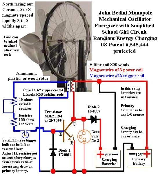
"The School Girl Radiant Energy Circuit and Motor is the most basic rendition of a patented circuit developed by John Bedini and researched by Dr. Peter A. Lindemann, based on the technology of Nikola Tesla, with follow-up work by Edwin Gray, Moray, and others. Bedini has done away with the need for a discharge gap. This "School Girl (Simplified)" design is the most basic presentation of the Bedini system. The circuit is run by an input battery, and charges an ouput battery, while turning a wheel, lined with magnets, that service to create a flux in the coils. There are some unusual characteristics observed in the process.

"Operation ~ The motor has to be started by an external push, after which it turns on its own from the firing of the coil electromagnet. It gradually increases in speeds until it reaches an optimum at around 300 rpm. Applying load to the wheel results in lower amperage going from the input battery because it is dependant on the rate of firing only.

"Features ~ Simple design. Inexpensive. Charger device whose oetput is friedly to batteries. Doesn't heat them, but actually refurbishes them. Charging takes less energy input by far than what is normally required, implicating Radiant (or whatever name is most suitable) energy infusion in the process. "

Assembly Notes ~

The Frame Stand needs to be non-magnetic, and mechanically stable front-to-back and left-to-right. The gap between the coil spool and wheel with magnets affixed (super-glue and tape) should be 1/8 inch. The gap should be variable for experimental purposes.

Determine the "North" end of the magnets with a compass, and label it. The "north" end of a compass needle will be attracted to the "south" pole of the magnet. All the magnets are mounted with the North pole facing out, toward the coil.

Equal-distance spacing of the magnets on the wheel's perimeter is not critical with one coil. There is a limiting minimum distance, but not a maximum. Spacing need not be uniform.  If you plan to add more coils --- with a separate circuit for each coil --- spacing must be symmetrical for proper firing. Do not space the magnets closer apart than 1.5 to 2 widths.

Coils are loosley wound with approximately 450 turns. The two wires on the coil are wound together. The number of turns is not critical, but an accurate count is necessary for proper scientific recording.

Miscellaneous Tips & Precautions ~

Spacing of the magnets on the wheel's perimeter is not critical with one coil. There is a imiting minimum distance, but not a maximum. Spacing need not be uniform.

Do not draw power from the battery while it is being charged. Charge one bank of batteries, and discharge another bank, switching between them.

This design can shock, though not dangerously.

If the neon bulb is not in place, The transistor will burn out if the neon bulb is not installed, and if the device is run without a receiver-load (battery) for the radiant energy. The neon bulb serves as a "shock absorber" for excess output energy.

Circuit Diagram (Drawn by Bedini) >>

B = Base
C = Collector
E = Emitter
R1 = 680 Ohms resistor
D1 = 1N4001 Diode
D2 = 1N4007 Diode
B1 = Run Battery
B2 = Charge Battery


Analogous Circuit >> 

Numbered Analogous Circuit >>

Key ~

1 --- Solder junction (insulated base [same for 2,3,4]) joining (a) wire coming from (+) battery "in" and (b) #20 magnetic wire to coil and then to collector
2 --- Solder junction joining (a) wire coming from (-) battery "in" and (b) emitter and (c) Diode 1N4001 and (e) #23 magnetic wire going to coil then resistor then base.
3 --- Resistor 680 Ohms, between (a) Base/Diode1N4001 and (b) #23 magnet wire going to coil then collector.
4 --- Solder junction joining (a) diode {19} (1N4007) and (b) wire to battery receiving charge.
5 --- Insulated wire coming from (+) battery "in"
6 --- #20 magnetic wire from (+) battery "in" to coil and then to collector
7 --- Insulated wire coming from (-) battery "in"
8 --- #23 magnet wire coming from emitter to coil to resistor.
9 --- Wire connecting 1N4001 diode to junction {2}
10 --- Transistor emitter, connected to junction {2}
12 --- Wire connecting 1N4001 diode to (a) base and (b) resistor {3}.
13 --- Transistor base: connected to resistor and diode 1N4001
14 --- Resistor connected to #23 magnet wire going to coil then to emitter.
15 --- from resistor to #23 magnet wire to coil to emitter
16 --- #20 magnet wire (per Bedini SG specs) from transistor's "collector" lead
17 --- connection of transistor's "collector" lead to wire to Diode 19 and to #20 magnet wire 16 to coil to input battery's positive lead
18 --- wire from transistor's "collector" lead to Diode 19
19 --- 1N4007 Diode 1000V
20 --- Insulated wire to positive terminal of battery receiving charge
21 --- Transistor (Different one in this photo than is called in these plans)
22 --- Aluminum plate heat sink
23 --- Neon bulb, between collector and emitter. (not shown in picture, nor schematic, but that is where it goes, and that is where it is situated on the school girl simplified demonstrated in Bedini's shop).

Transistor 2N3055 >>


http://www.youtube.com/results?search_query=Bedini&suggested_categories=28%2C26%2C27&page=7

http://www.youtube.com/watch?v=nA2KtZ45nXA

http://www.youtube.com/watch?v=ZU10XJn67ao

http://www.youtube.com/watch?v=M_f4cXKjybI

http://www.youtube.com/watch?v=uHh5AqQ4_xw

http://www.youtube.com/watch?v=6mKOL0JGUxw

http://www.youtube.com/watch?v=yi7cmUpMdX8

http://www.youtube.com/watch?v=g9ARja0DiT0

http://www.youtube.com/watch?v=hnHDRjO7BGE

http://www.youtube.com/watch?v=wSGnZPZpR_I

http://www.youtube.com/watch?v=zJySgeSpJpQ

http://www.youtube.com/view_play_list?p=45FBDDAB0F0642B7&playnext=1&playnext_from=PL&v=mOGjLDU2lX8

http://www.youtube.com/view_play_list?p=45FBDDAB0F0642B7&playnext=1&playnext_from=PL&v=2hUSGB0dbK8

http://www.youtube.com/view_play_list?p=45FBDDAB0F0642B7&playnext=1&playnext_from=PL&v=yi7cmUpMdX8

http://www.youtube.com/watch?v=nlO8UDsc-Fc

http://www.youtube.com/watch?v=8oapvf7wVtw

http://www.youtube.com/watch?v=eDS9qk-Nw4M

http://www.youtube.com/view_play_list?p=BFDE1E217BCB7D90&playnext=1&playnext_from=PL&v=g9ARja0DiT0

http://www.youtube.com/view_play_list?p=BFDE1E217BCB7D90&playnext=1&playnext_from=PL&v=N2ZKDytQKnM

http://www.youtube.com/view_play_list?p=BFDE1E217BCB7D90&playnext=1&playnext_from=PL&v=zJySgeSpJpQ

http://www.youtube.com/watch?v=CVa2s93SouU

http://www.youtube.com/watch?v=1oXRhyulQ9c

http://www.youtube.com/watch?v=B-Mi90gEdSE

http://www.youtube.com/watch?v=JJillOTsmrM

http://www.youtube.com/watch?v=Qn2aZchRReo

http://www.youtube.com/watch?v=jG4nU1cimZ4&feature=fvsr

http://www.youtube.com/watch?v=jU5qZqImOVM&feature=fvsr

http://www.youtube.com/watch?v=KfdcwjqKebQ&feature=fvsr

http://www.youtube.com/watch?v=ayHOXmRDGuo&feature=fvsr

http://www.youtube.com/watch?v=6CUz00uVuhE&feature=fvsr

http://www.youtube.com/watch?v=mOGjLDU2lX8

http://www.youtube.com/watch?v=vy9nIg6kBWQ

http://www.youtube.com/watch?v=GPet3K6Ujb4

http://www.youtube.com/watch?v=67QJOn39FqU

http://www.youtube.com/watch?v=mpGJvN08GsU

http://www.youtube.com/watch?v=4lpWJpLj2ZM

http://www.youtube.com/watch?v=w6qEZZ165i0

http://www.youtube.com/watch?v=yDtXR_1Ubs8

http://www.youtube.com/watch?v=5f69vjd8Pjs

http://www.youtube.com/watch?v=HbWR8Y999cM

http://www.youtube.com/watch?v=3YN6h2Qgv0o

http://www.youtube.com/watch?v=Qofqi9dMqwE

http://www.youtube.com/watch?v=8RsFMyZbj1I

http://www.youtube.com/watch?v=sGVvdfdHs_g

http://www.youtube.com/watch?v=0U20V7Kh_kc

http://www.youtube.com/watch?v=gU_-1Q0QGwQ

http://www.youtube.com/watch?v=4P1zr58MVfI

http://www.youtube.com/watch?v=Qwbz_YAAnRo

http://www.youtube.com/watch?v=k2a0YFGdRBM

http://www.youtube.com/watch?v=ZrN1lG274k4

http://www.youtube.com/watch?v=dDXM23NDarQ

http://www.youtube.com/watch?v=3pK5kVHjYoU

http://www.youtube.com/watch?v=gazAa7XBp6w

http://www.youtube.com/watch?v=RCIjIMDsGVs

http://www.youtube.com/watch?v=qImkQg2CupI

http://www.youtube.com/watch?v=I-4-K94Dsb4

http://www.youtube.com/watch?v=-2gvjzyFG5Q

http://www.youtube.com/watch?v=iTZfyQlPWug

http://www.youtube.com/watch?v=y_E39pmoFN4

http://www.youtube.com/watch?v=YsobVuzUSiE

http://www.youtube.com/watch?v=ce1wiMfEnpM

http://www.youtube.com/watch?v=sSc-dPSl3Uc

http://www.youtube.com/watch?v=TSYxBwjrGv4

http://www.youtube.com/watch?v=2hUSGB0dbK8

http://www.youtube.com/watch?v=bDm3s0Jvl0k

http://www.youtube.com/watch?v=EsKlUV-MkPE

http://www.youtube.com/watch?v=Tb2-ka6T3Zk

http://www.youtube.com/watch?v=qImkQg2CupI

http://www.youtube.com/watch?v=V354l__dfps

http://www.youtube.com/watch?v=0U20V7Kh_kc

http://www.youtube.com/watch?v=GuTrmgTpQkE

http://www.youtube.com/watch?v=iTG2U8e6Mdo

http://www.youtube.com/watch?v=sfb2gYm-_YM

http://www.youtube.com/watch?v=Qwbz_YAAnRo

http://www.youtube.com/watch?v=hQBCwks5P_I

http://www.youtube.com/watch?v=kNHRe6xy0QQ

http://www.youtube.com/watch?v=6W9DLQuYV10

http://www.youtube.com/watch?v=ZitkVFG6Qj8

http://www.youtube.com/watch?v=3RugNE6VxjE

http://www.youtube.com/watch?v=5hWBihg_Oi8

http://www.youtube.com/watch?v=WXWAQ3zTZNw

http://www.youtube.com/watch?v=gD5_dORsmcI

http://www.youtube.com/watch?v=Fg4QlVjOnvQ

http://www.youtube.com/watch?v=IwSUh8A5UIM

http://www.youtube.com/watch?v=l0r9x8cBOrI

http://www.youtube.com/watch?v=AUdrEhFxOM0

http://www.youtube.com/watch?v=GTjglYb9H3A

http://www.youtube.com/watch?v=glBlOTDxn44

http://www.youtube.com/watch?v=oVJF4iDUBvk

http://www.youtube.com/watch?v=HIvA4uo72wE

http://www.youtube.com/watch?v=tXALKcR1ORM

http://www.youtube.com/watch?v=QGprVym7abM

http://www.youtube.com/watch?v=eiLm3urmLXM

http://www.youtube.com/watch?v=jplGJ_cH6pQ

http://www.youtube.com/watch?v=2Ej11pclxWw

http://www.youtube.com/watch?v=xFDREWe4niE

http://www.youtube.com/watch?v=WcsYhbA74VM

http://www.youtube.com/watch?v=eiLm3urmLXM

http://www.youtube.com/watch?v=vcYAMloddZU

http://www.youtube.com/watch?v=9oeSebSLWq0

http://www.youtube.com/watch?v=kXSOLcQlOew

http://www.youtube.com/watch?v=XuVtKYfSDI8

http://www.youtube.com/watch?v=0Y62-5aSiKo

http://www.youtube.com/watch?v=appORnbTIrc

http://www.youtube.com/watch?v=S3XjBXIgmxY

http://www.youtube.com/watch?v=zfIOE5YXQRs

http://www.youtube.com/watch?v=TSRBbyqBrUg

http://www.youtube.com/watch?v=avvX4yAyS1s

http://www.youtube.com/watch?v=lHXt5mwcvl0

http://www.youtube.com/watch?v=zdtcoJEtDqQ

http://www.youtube.com/watch?v=qYfAzIytEJ8

http://www.youtube.com/watch?v=UVpqAVhgNAo

http://www.youtube.com/watch?v=j-fETLsRiJg

http://www.youtube.com/watch?v=Oclt8RXJBFg

http://www.youtube.com/watch?v=ajtYT-40nZM

http://www.youtube.com/watch?v=0FG3alMA6vU

http://www.youtube.com/watch?v=wt8Ut2maA8M

http://www.youtube.com/watch?v=LhdvLNvE5RY

&c...