The Oklahoman(12-25-02)
How the IWA Works
US4,568,042
US 4,579,300
IWA Toy Co.
US7147183 -- Lift system for an aerial crane and propulsion system for a vehicle
US7258302 -- AIRCRAFT INTERNAL WING AND DESIGN
"100
MPH From Hand-Launched Glider!"
Mustang
Inventor's High-Speed Toy Takes Off
by Gregory Potts
MUSTANG (OK) --- Inventor Robert Carr is concerned that parents will be afraid when they learn the truth about the Xstream Flyer, a new toy airplane his company is selling.
It can fly at speeds up to 100 miles per hour. In fact, because of its unique aerodynamic design, the hand-held plane actually picks up speed once it starts soaring.
"You expect to see this normal, slow-flying glider and this thing takes off like a rocket," he said. But the toy is made of such a soft, flexible plastic that it cannot hurt anyone, even at high speeds, he said. Although airplanes have long been a staple of the toy world, Carr insists that his invention is different.
"It's totally different from any airplane you can find anywhere," he said. The plane's speed and long flight distances are made possible by a duct in the wings. In addition to its speed, propelled by nothing more than a flick of the wrist, the buoyant plane also can zoom underwater. In fact, the technology, for which he has already received two patents, is so advanced that Carr thinks it could be applied to real airplanes. Carr has applied for six more patents on the toy.
Carr, a flight instructor for 26 years, plans to use toy profits to fund research for real-life uses for the Xstream. Carr founded IWA Toy Co. in Mustang to sell his product. In its first four weeks on the market, IWA Toy has sold 50,000 planes, which retail for $12.95. The toys got a huge boost when they were featured in Discover magazine.
Locally, they are at Larry's IGA in Mustang and several 7-Eleven stores. They are also available at the company's Web site at http://www.iwatoyco.com. Carr said the company could have sold more of the toys, which are made in China, if the first shipment had not been held up in Los Angeles by the dock workers' strike. The toys are sold out while the company awaits a new shipment.
Carr is planning a major expansion in the toy's production and distribution. By March, he expects to be selling 400,000 gliders per month through 15,000 stores. Along with this growth, Carr said the young company is already looking for new offices. He hopes to stay in Mustang. The company employs eight full-time employees and "dozens" of consultants. The Xstream is only the beginning for IWA Toy Co., Carr said. The company's next toy launch will be a radio-controlled plane, possibly on the market as soon as July.


Robert J. Carr

by Robert Carr
The coanda directs the airflow downward from its trailing edge, turbocharging the internal wing and separating the airflow from the underside of the duct top. This arrangement of airfoils reduces drag, enhances lift and thrust output.
The Xstream and related toy industry products are based on the Internal Wing Aircraft (IWA) technology, which is a design that generates extraordinary lift and thrust by the action of air moving through a shaped duct. The technology and multiple applications related to aerospace designs are covered under U.S. Patents 4,568,042 and 4,579,300 as well as current patent pending.
The extraordinary lift and thrust characteristics of the IWA design are a result of the duct, the bottom of which serves as the internal wing, and the coanda, which is the leading surface that extends toward the nose on each side and looks like a wing.
As the glider is moving through a flowing medium (air or water), or ascthat medium is being pushed through the system in powered versions, the air or water comes off the upper trailing edge of the coanda in a downward direction toward the internal wing.
The downward direction of the air or water has two effects on the flow through the system. First, it separates the flow from the top of the duct. This separation is what inhibits the pressure under the top of the duct from decreasing.
If the pressure under the top of the duct were allowed to decrease too much then the positive lift generated from the bottom of the duct, the internal wing, would be negated by the negative lift generated by the top of the duct.
Second, the downward direction of the flow off the back of the coanda laminates this air or water to the flow that has come into the system and onto the internal wing from under the coanda.
Therefore, the IWA design doubles the mass of the air or water that is flowing over and operating on the internal wing. The lift produced increases exponentially with the mass of the medium operating on the wing. Also, the lamination process combined with the confining effect of the sides of the duct squeezes the flow in much the same fashion as your thumb squeezes the flow of water when you place it over the end of a running garden hose.
This squeezing
action produces a venturi effect that results in an increase
in velocity of the flow through the internal wing system.
Lift also increases exponentially with the velocity of the
flow through the system.
In addition, the increase in velocity produces thrust. We call this thrust-producing effect Dynamic Natural Propulsion.
The venturi effect is the same phenomenon utilized by designers of jet engines. So, in essence the IWA system becomes its own engine. The bottom line is the mass of the flow operating on the wing is doubled and the velocity of the flow through the system is dramatically increased. All of this adds up to a design that, incredibly, creates its own lift and thrust.

( Image Source: IWA Toy
Co. )
Abstract
Lift for an aircraft is provided by forming a longitudinal lifting duct therethrough, said lifting duct having a substantially planar roof and a longitudinally cambered floor. When the aircraft is driven forwardly, a stream of air enters and passes through the lifting duct and the contouring of the floor of the lifting duct give rise to a pressure gradient in the air stream which result in a higher pressure on the roof of the lifting duct than on the floor thereof so that the pressure difference provides lift for the aircraft.
Claims
What is claimed is:
1. In an externally wingless aircraft having a fuselage and means for providing lift for the aircraft, the improvement wherein an internally disposed lifting duct having an essentially unobstructed opening extending entirely therethrough is formed longitudinally through the fuselage, said lifting duct having a substantially planar roof extending entirely across the width thereof and a longitudinally cambered floor such that the lifting duct forms said means for providing lift for the aircraft and provide an internal wing therefor, wherein the fuselage has opposed forward and rear ends intersected by said duct such that the duct opens forwardly and rearwardly of the aircraft; and wherein the cambering of the floor of the duct is characterized as being formed by a single portion of the floor arching upwardly in a direction toward the roof of the duct beginning near the forward end of the fuselage and downwardly in a direction away from the roof and ending near the rear end of the fuselage.
2. The aircraft of claim 1 further comprising:
propulsion means for forming a rearwardly directed air stream so as to propel the aircraft; and means for directing at least a portion of said air stream through the duct.
3. The aircraft of claim 2 wherein the means for directing at least a portion of said air stream through the duct comprises:
means forming a transverse duct in portions of the fuselage underlying the floor of the lifting duct near the forward end of the aircraft, and transverse duct communicating with the lifting duct via a transverse slot formed in the floor of the lifting duct and extending to the transverse duct; and
means for diverting at least a portion of said air stream into the transverse duct.
4. The aircraft of claim 1 wherein the fuselage comprises a transverse flap forming a portion of the floor of the lifting duct adjacent the forward end of the aircraft, said flap pivotally connected at the side thereof nearest the rear end of the fuselage for pivotation about a transverse axis; and
means for pivoting said flap.
5. The aircraft of claim 1 wherein the floor of said lifting duct has a first portion extending longitudinally along one side of the lifting duct and a second portion extending longitudinally along the opposite side of the lifting duct, the first and second portions of the floor of the lifting duct meeting at a positive dihedral at the center of the lifting duct.
6. The aircraft of claim 1 wherein portions of the fuselage forming the roof of the lifting duct at the rear end of the aircraft are formed into two transversely extending, pivotable flaps and portions of the fuselage forming the floor of the lifting duct at the rear end of the aircraft are formed into two transversely extending, pivotable flaps so as to provide pitch and roll control for the aircraft.
7. The aircraft of claim 1 further comprising a plurality of vertically extending internal rudders pivotally mounted within the lifting duct near the rear end of the aircraft.
8. The aircraft of claim 7 wherein portions of the fuselage forming sides of the lifting duct at the rear end of the fuselage are formed into vertically extending flaps pivotable about the leading edges thereof laterally outwardly from the fuselage.
Description
This application is a substitute application for my earlier related application Ser. No. 092,349, filed Nov. 8, 1979, now abandoned.
The present invention relates generally to aircraft, and, more particularly, but not by way of limitation, to means for providing lift for aircraft.
It is common knowledge that air pressure at a point on the surface of a moving object is a function of the velocity with which air streams over the surface at that point. Indeed, this principle is the basis for aircraft design; that is, it is common practice to shape the wings of an aircraft so that the velocity of air streaming over the top surface of each wing is greater than the velocity of air streaming over the bottom surface of the wing. This velocity differential, achieved by the contour of the wing, results in a pressure differential across the wing so that a net force, lift, is exerted on the wing to support the aircraft in flight.
The present invention exploits this principle in a novel manner to similarly achieve lift for an aircraft. In particular, the present invention contemplates the establishment of a pressure gradient in air streaming through a duct formed through the fuselage of an aircraft to provide lift for the aircraft. The pressure gradient increases from the floor of the duct to the roof thereof so that a larger force is exerted on the roof of the duct than on the floor thereof and the lift on the aircraft is the difference in these two forces. To this end, the duct extends longitudinally through the fuselage so that, as the aircraft is driven forwardly through the air, air enters and streams through the duct. The pressure gradient is then achieved by forming portions of the fuselage defining the roof of the duct such that the roof is substantially planar from the forward end of the aircraft to the rear end thereof and by forming portions of the fuselage defining the floor of the duct such that the floor is cambered along the longitudinal extent thereof. This camber of the floor of the duct results in a higher air stream velocity near the floor of the duct than near the roof of the duct to establish the desired pressure gradient.
The use of a duct through the fuselage of an aircraft, rather than a wing mounted externally of the fuselage, results in a number of benefits. A lifting duct will generally result in a more compact aircraft than can be constructed using external wings and the use of a duct offers flexibility in the design of aircraft to meet varying purposes. Since the shape of the exterior of an aircraft having a lifting duct can remain fixed while the profile of the duct is changed, such change can be used to vary the performance characteristics of the aircraft so that the aircraft designer is given a design variation capability that will generally not be available where external wings are used to lift the aircraft. That is, changes in performance can be accomplished by shaping structural members which provide the longitudinal camber of the floor and the effect of such shaping can be determined independently of other factors involved in the overall interaction of the aircraft with the air through which the aircraft will move. Moreover, since the floor of the duct is within the fuselage, an aircraft constructed in accordance with the present invention offers the capability of providing mechanisms for shaping the floor in flight without affecting the structural integrity of the aircraft as might be the case were shaping attempted in a wing extending in cantilever fashion from the fuselage. In addition, the formation of lifting surfaces within a duct permits a direct utilization for lifting purposes of air streams produced by engines and normally used to propel an aircraft so as to provide lift via the forward motion of the aircraft through the air. With lifting surfaces formed in a duct, such streams can be diverted into the duct to pass therethrough and provide lift so that the aircraft can be flown at lower speeds than would generally be the case for comparable aircraft having external wings.
An object of the present invention is to provide an aircraft which utilizes air streaming through a duct to provide lift.
Another object of the present invention is to enable compactness of aircraft design.
Yet a further object of the present invention is to provide an enhanced flexibility in aircraft design.
Still another object of the present invention is to provide an aircraft with a low flight speed capability.
Another object of the present invention is to provide variable flight characteristics in an aircraft.
Other objects, advantages and features of the present invention will become clear from the following detailed description of the preferred embodiments of the invention when read in conjunction with the drawings and appended claims.
BRIEF DESCRIPTION OF THE DRAWINGS
FIG. 1 is a perspective view of an aircraft constructed in accordance with the present invention.

FIG. 2 is a schematic cross-section taken along line 2--2 of FIG. 1.

FIG. 3 is a fragmentary perspective view of the aircraft of FIG. 1 showing rear portions of the aircraft.

FIG. 4 is a schematic cross-section in side elevation of a second embodiment of an aircraft constructed in accordance with the present invention.

FIG. 5 is a fragmentary cross-section in side elevation of another embodiment of an aircraft constructed in accordance with the present invention.

FIG. 6 is a fragmentary cross-section in side elevation similar to FIG. 5 but showing a different configuration of the lift duct floor.

FIG. 7 is a fragmentary, schematic cross-section in side elevation of another embodiment of an aircraft constructed in accordance with the present invention.

FIG. 8 is a fragmentary front elevational view of another embodiment of an aircraft constructed in accordance with the present invention.

DESCRIPTION OF FIGS. 1 THROUGH 3
Referring now to the drawings in general and to FIGS. 1, 2 and 3 in particular, shown therein and designated by the general reference numeral 10 is one preferred embodiment of an aircraft constructed in accordance with the present invention. In general, the aircraft 10 comprises a fuselage 12 having: a forward end 14; a rear end 16; a first side 18; a second side 20; a top 22; and a bottom 24; the terms top and bottom being used herein to denote generally uppermost and lowermost surfaces of the aircraft 10 at such times that the aircraft 10 is in level flight. The aircraft 10 further comprises: a vertical stabilizer 26 mounted on the top 22 of the fuselage 12 near the rear end 16 thereof and extending vertically therefrom at such times that the aircraft 10 is in level flight; a first engine 28 mounted on the first side 18 of the fuselage 12 near the forward end 14 thereof; and a second engine 30 mounted on the second side 20 of the fuselage 12 near the forward end 14 thereof. For purposes of illustration, the engines 28 and 30 have been drawn as jet engines. However, the present invention is not limited to aircraft having such propulsive means; rather, any type of engine that produces a rearward air stream so as to provide thrust for the aircraft 10 can be used to propel the aircraft 10 without departing from the scope and spirit of the present invention. The stabilizer 12 can have an integral, external rudder 32 as has been shown in the drawings and, when such is the case, conventional control mechanisms (not shown) are provided for pivoting the rudder 32 for guidance purposes. The aircraft 10 further comprises conventional landing gear (not shown).
Lift for the aircraft 10 is provided by a lifting duct 34 which intersects the forward and rear ends, 14 and 16 respectively, of the fuselage 12 and extends longitudinally through the fuselage 12 between the ends 14 and 16 thereof. As has been indicated in FIGS. 1 and 3, the duct 34 has a generally rectangular transverse cross-section and FIG. 2 has been provided to show the longitudinal cross-section of the duct 34. (The fuselage 12, including portions thereof defining the duct 34, is constructed using conventional air frame construction methods so that a detailed discussion of the construction of the air frame need not be given for purposes of the present disclosure. Accordingly, conventional framing members, such as spars, stringers and the like, have not been shown in the drawings in the interest ofclarity of description. Rather, where conventional framing methods would be employed in constructing portions of the aircraft 10, hatching has been used in drawings of cross-sections to indicate the use of such conventional methods.) As is indicated by a comparison of FIGS. 1 and 2, the duct 34 has a roof 36 which is substantially planar in form and which is oriented relative to the top 22 and bottom 24 of the fuselage 12 so as to be disposed substantially horizontally at such times that the aircraft 10 is in level flight. The floor 38 of the duct 34, on the other hand, has a central portion 40 which arches upwardly toward the roof 36 of the duct 34. That is, the floor 38 of the duct 34 is provided with a camber along the longitudinal extent thereof. This camber in the floor 38 of the duct 34 provides lift for the aircraft 10 as will be described below.
The aircraft 10 is provided with a plurality of internal rudders disposed within the duct 34 near the rear end 16 of the fuselage 12 and one of these rudders, designated 42, is shown in FIG. 2. The remaining rudders, designated 44 and 46, have been shown in FIG. 3 to which attention is now directed. As shown in FIG. 3, each of the rudders 42-46 has a forward, rod-shaped portion 48 and the upper and lower ends of the portions 48 extend into apertures (not shown) formed in the roof 36 and floor 38 of the lifting duct 34. As in the case of the external rudder 32, conventional control mechanisms are provided for pivoting the rudders 42-46 about the rod-shaped portions 48 thereof. Fin portions 50 of the rudders 42-46 extend from the rod-shaped portions 48 thereof generally toward the rear end 16 of the fuselage 12 for guidance of the aircraft as will be discussed below.
As will be noted in FIG. 3, portions of the fuselage 12 adjacent the rear end 16 thereof are constructed separately from remaining portions of the fuselage 12 which extend to the forward end 14 thereof. Specifically, portions of the fuselage 12 which form the sides of the lifting duct 34 at the rear end 16 of the fuselage 12 are formed into a vertically extending flap 52, at the first side 18 of the fuselage 12, and another vertically extending flap 54, at the second side 20 of the fuselage 12. The flaps 52, 54 are pivotally connected to remaining portions of the fuselage 12 at the leading edges 56, 58 thereof via internal hinge members (not shown) and conventional control mechanisms are provided to pivot the flaps 52, 54 on remaining portions of the fuselage 12. Specifically, the control mechanisms interconnect the flaps 52 and 54 with the rudders 42-46 so that, each time the rudders 42-46 are pivoted in the direction designated 60 in FIG. 3 for rudder 44, flap 52 is pivoted laterally outwardly from the fuselage 12; that is, in the direction designated 62 in FIG. 3. Similarly, each time the rudders 42-46 are pivoted in the direction designated 64 in FIG. 3 for rudder 44, the flap 54 is pivoted laterally outwardly from the fuselage 12; that is, in the direction designated 66 in FIG. 3. Any conventional control mechanism can be used for concertedly pivoting the flaps 52, 54 and the rudders 42-46. For example, hydraulic actuating cylinders (not shown) connected to portions of the flaps 52, 54 near the leading edges 56, 58 thereof and connected to the rod-shaped portions 48 of the rudders 42-46 and a suitable hydraulic valve circuit can be used for this purpose.
Portions of the fuselage 12 forming the roof 36 of the lifting duct 34 at the rear end 16 of the fuselage 12 are formed into two transversely extending flaps 68, 70 and portions of the fuselage 12 forming the floor 38 of the lifting duct 34 are similarly formed into two transversely extending flaps 72, 74. The flaps 68-74 are pivotally connected to remaining portions of the fuselage 12 in the manner that the flaps 52, 54 are connected to such remaining portions of the fuselage 12 and a conventional control mechanism is provided for pivoting the flaps 68-74 for pitch and roll control of the aircraft 10. That is, the flaps 68-70 can be pivoted upwardly or downwardly as a unit to deflect air exiting the lifting duct 34 upwardly or downwardly so as to raise or lower the forward end 14 of the aircraft 10. Similarly, the flaps 68 and 70, near the first side 18 of the fuselage 12, can be pivoted upwardly (or downwardly) while the flaps 70 and 74, near the second side 20 of the fuselage 12, can be pivoted downwardly (or upwardly) so that, as will be discussed below the flaps 68-74 form ailerons for the aircraft 10.
OPERATION OF FIGS. 1, 2 AND 3
The aircraft 10 is operated in a manner similar to the operation of a conventional aircraft; that is, the engines 28, 30 project streams of air rearwardly to provide thrust which propels the aircraft 10 forwardly and lift for the aircraft 10 is provided by the motion of the aircraft 10 through the air. More particularly, as the aircraft 10 moves through the air, air will enter the lifting duct 34 at the forward end 14 of the fuselage 12 and stream therethrough so as to exit therefrom at the rear end 16 of the fuselage 12. As the air streams through the lifting duct 34, the contour of the cambered portion 40 of the floor 38 of the lifting duct 34 results in a higher stream velocity at the floor 38 of the lifting duct 34 than at the roof 36 thereof so that the air streaming through the lifting duct 34 exerts a higher pressure at the roof 36 than at the floor 38. Accordingly, a pressure gradient is established vertically across the lifting duct 34 and such pressure gradient results in a larger force being exerted on the roof 36 of the lifting duct 34 than is exerted on the floor 38 thereof by air streaming through the lifting duct 34. This difference in the net forces exerted on the roof 36 and floor 38 of the lifting duct 34 provide the requisite lift necessary to maintain the aircraft 10 in flight.
Should it be desired to turn the aircraft 10, the rudders 32 and 42-46 and the flaps 68-74 provide the aircraft 10 with the capability of making a banked turn in the manner of a conventional aircraft. In particular, should it be desired to turn the aircraft to the left, air streaming through the lifting duct 34 generally along the first side 18 of the fuselage 12 is deflected upwardly as it exits the duct 34 by pivoting the flaps 68 and 72 upwardly and air streaming through the duct 34 generally along the second side 20 of the fuselage 12 is deflected downwardly by pivoting the flaps 70 and 74 downwardly. The deflection of air generally upwardly as it leaves the duct 34 near the first side 18 of the fuselage 12 and the deflection of air downwardly as it leaves the duct 34 generally along the second side 20 of the fuselage 12 exerts a coupled about the longitudinal axis of the fuselage 12 in substantially the same manner that air deflected by the ailerons on the wings of a conventional aircraft give rise to a couple about the longitudinal axis of the fuselage of such conventional aircraft. The couple so provided about the longitudinal axis of the fuselage 12 lowers portions of the fuselage 12 adjacent the first side 18 thereof while raising portions of the fuselage 12 adjacent the second side 20 thereof. The rudders 32 and 42-46 are pivoted in the direction 60 shown in FIG. 3 to deflect air laterally of the first side 18 of the fuselage 12 of the aircraft 10 so as to pivot the forward portions of the aircraft 10 toward the left as seen by occupants of the aircraft 10. The concurrent pivotation of the flap 52 in the direction 62 as the rudders 32, 42-46 are pivoted in the direction 60 prevents interference with the diversion of air streaming from the lifting duct 34 laterally outwardly of the first side 18 of the fuselage 12 so that the pivotation of the flap 52 enhances the turning capability of the aircraft 10 via the internal rudders 42-46. A banking turn to the right can be made by pivoting the rudders 32, 42-46 and the flaps 68-74 in directions opposite to those utilized for making a turn to the left and the pivotation of the flap 54 in the direction 66 in such case has an effect similar to the effect of pivotation of the flap 52 at such times that a turn to the left is made.
DESCRIPTION OF FIG. 4
Referring now to FIG. 4, shown therein and designated by the general reference numeral 10a is a schematic cross-section of a second embodiment of an aircraft constructed in accordance with the present invention. The aircraft 10a comprises a fuselage 12a having a lifting duct 34a and a stabilizer 16a similar to the stabilizer 16 of the aircraft 10. As in the aircraft 10, portions of the fuselage 12a near the rear end 16a thereof can be formed into flaps (not shown) which provide ailerons for the aircraft 10a and internal rudders (not shown) can be mounted in the lifting duct 34a as in the lifting duct 34 of the aircraft 10.
The aircraft 10a differs from the aircraft 10 in that the engines of the aircraft 10a can be utilized directly to provide lift for the aircraft 10a in addition to indirect utilization for such purpose wherein the engines drive the aircraft forwardly and the forward motion results in a stream of air passing through the lifting duct 34a. The direct lift capability is in part provided by forming a transverse duct 76 in portions of the channel 12a forming the floor 38a of the fuselage 12a so that the transverse duct 76 underlays the floor 38a of the lifting duct 34a near the forward end 14a of the fuselage 12a. The transverse duct 76 extends substantially the width of the lifting duct 34a and a slot 78, similarly extending substantially the width of the lifting duct 34a is formed in the floor 38a thereof to communicate the transverse duct 76 with the lifting duct 34a. The slot 78 is delimited by the arched portion 40a of the floor 38a of the duct 34a and a rearwardly sweeping overhang 80 which is disposed generally forward of the arched portion 40a and extends over a nose 82 formed at the forward end of the arched portion 40a of the floor 38a of the duct 34a so that air forced into the transverse duct 76, as will be discussed below, is projected rearwardly over the arched portion 40a of the floor 38a of the duct 34a by the slot 78 to provide lift for the aircraft 10a.
In order to more clearly show the manner in which the direct lift capability is provided, FIG. 4 has been drawn in contemplation of a single engine aircraft and such engine, shown schematically in FIG. 4 and designated 28a therein, is positioned, by way of example, on the bottom 24a of the fuselage 12a. (As will be clear from the description to follow, the aircraft 10a can be a multi-engine aircraft and the engines need not be positioned on the bottom of the aircraft for the provision of the direct lift capability.) The engine 28a is encased within a shroud 84 which underlays the transverse duct 76 and the transverse duct has an opening 86 into the shroud 84. In normal flight, wherein the aircraft 10a is operated, a cover 88 extends over the opening 86 so that an air stream is projected rearwardly by the engine 28a to produce thrust which propels the aircraft 10a. Such propulsion forces air through the lifting duct 34a to produce lift in the same manner that lift is produced in the aircraft 10. The cover 88 is pivotally attached, at the rear end 90 thereof, to the fuselage 12a and conventional positioning means; for example, a hydraulic actuating cylinder and suitable hydraulic circuitry, are provided for positioning the cover 88 over the opening 86 as has been shown in solid lines in FIG. 4 and, alternatively, for pivoting the cover 88 into the shroud 84 to the position shown in phantom lines in FIG. 4 and designated therein by the numeral 92. Thus, the cover 88 can be positioned so as to divert a portion of the air stream projected by the engine 28a into the transverse duct 76 so that such air stream is channeled by the slot 78 into a stream of air passing over the cambered portion 40a of the floor 38a of the duct 34a. (While the cover 88 has been drawn in FIG. 4 so that only a portion of the air stream projected by the engine 28a is diverted to the lifting duct 34a, it will be clear to those skilled in the art that the cover 88 and shroud 84 can be shaped to permit the diversion of the entirety of such air stream into the transverse duct 76 and, therefrom, into the lifting duct 34a.) Thus, the aircraft 10a can be placed in a high speed flight configuration, by positioning the cover 88 to overlay the opening 86, wherein the aircraft 10a is operated in the same manner that the aircraft 10 is operated and, alternatively, the aircraft 10a can be placed in a low speed configuration, by pivoting the cover 88 to the position designated by the numeral 92 in FIG. 4, wherein the air stream produced by the engine 28a is diverted from the shroud 84 into the transverse duct 76 and, therefrom, to the lifting duct 34a so that the engine 28a is used directly for providing lift for the aircraft 10a. The operation of the aircraft 10a in the high speed configuration thereof is substantially the same as the operation of the aircraft 10 and the provision of the low speed configuration permits a variation from the operation of the aircraft 10 wherein the aircraft 10a is flown at a lower speed than might be possible with the aircraft 10.
DESCRIPTION OF FIGS. 5 AND 6
Referring now to FIGS. 5 and 6, shown therein is a schematic partial cross-section in side elevation of another embodiment of an aircraft, designated 10b in FIGS. 5 and 6, constructed in accordance with the present invention. Specifically, the portion of the aircraft 10b shown in FIGS. 5 and 6 includes the arched portion 40b of the floor 38b of the duct 34b. For purposes of example, it is contemplated that the aircraft 10b will be provided with a direct lift capability as in the aircraft 10a and portions of the fuselage (not numerically designated in FIGS. 5 and 6) which define the floor 38b and the transverse duct 76b have been indicated schematically in FIGS. 5 and 6. However, it will be clear from the discussion to follow that the aircraft 10b can be provided with only the indirect lift capability such as is the case with the aircraft 10.
The aircraft 10b is provided with a variable lift capability in that means are provided to vary the longitudinal camber of the floor 38b; that is, to provide a varying degree of arching of the arched portion 40b of the floor 38b of the duct 34b. To this end, the fuselage of the aircraft 10b comprises a sheet of metal 94 which forms the portion 40b of the floor 38b of the duct 34b. The sheet 94 is pivotally attached to remaining portions of the fuselage at the leading edge 96 thereof; that is, at the end thereof nearest the forward end of the fuselage of the aircraft 10b. The sheet 94 extends toward the rear end of the fuselage of the aircraft 10b and terminates at a trailing edge designated 98 in FIGS. 5 and 6. A plurality of guide rods 100 (one guide rod 100 has been shown in the drawings) are attached to the fuselage of the aircraft 10b adjacent the underside 102 of the sheet 94 and adjacent the trailing edge 98 thereof. The guide rods extend longitudinally of the fuselage of the aircraft 10b and a plurality of guide members 104 (only two guide members 104 are shown in the drawings) are mounted on the underside 102 of the sheet 94 so that two of the guide members 104 will slidingly engage each guide rod 100. Thus, the guide rods 100 and guide members 104 support the trailing edge 98 of the sheet 94 for longitudinal sliding movement in relation to remaining portions of the fuselage of aircraft 10b. (It will be noted that the guide rods 100 can be curved and portions thereof will, at times, extend through the sheet 94. Slots can be provided in the sheet 94 for this purpose. Such curvature is utilized to shape portions of the sheet 94 near the trailing edge 98 thereof as the camber of the floor 38b of the duct 34b is changed.)
A plurality of stiffening members, including members 106 which have the form of metal slats and members 108 which have an L-shaped cross-section are attached to the underside 102 of the sheet 94 and extend transversely to the duct 34b across the underside 102 of the sheet 94. The stiffening members 106, 108 provide the sheet 94 with sufficient rigidity to transmit lift produced thereby in conjunction with the roof (not shown) of the duct 34b to the fuselage of the aircraft 10b while, concurrently, permitting longitudinal flexure of the sheet 94. Such flexure is used to vary the camber of the floor 38b so that the aircraft 10b will have a variable lift capability. To this end, the aircraft 10b is provided with a plurality of stiffening member positioning assemblies and, by way of example, three stiffening member positioning assemblies have been shown in FIGS. 5 and 6 and designated 110, 112 and 114 therein. (As will be clear from the discussion to follow, the number of stiffening member positioning assemblies can be varied in accordance with particular applications wherein the variable lift capability of the aircraft 10b is utilized.) The stiffening member positioning assemblies 110, 112 and 114 are substantially identical; that is, the assemblies 110, 112 and 114 differ only in the dimensions of elements thereof, so that it will not be necessary for purposes of the present disclosure to describe each of the stiffening member positioning assemblies 110, 112 and 114 in detail. Rather, the stiffening member positioning assembly 110 will be described and reference numerals of elements of stiffening member positioning assemblies 112 and 114 will be identified in the drawings with the numerals used to identify substantially identical elements of the stiffening member positioning assembly 110.
The stiffening member positioning assembly 110 comprises a transverse shaft 116 which is secured by suitable bearings to the fuselage of the aircraft 10b so that the shaft 116 can be pivoted about an axis transverse to the longitudinal extent of the lifting duct 34b and parallel to the roof (not shown in FIGS. 5 and 6) thereof. A bell crank 118 is fixed to the shaft 116 to pivot therewith and a connecting rod 120 is pivotally connected to the upper end of the bell crank 118. The connecting rod 120 extends torward one of the L-shaped stiffening members 108 and is pivotally connected thereto via a suitable connector 122 mounted on the stiffening member 108. The lower end of the bell crank 118 of each stiffening member positioning assembly 110-114 is pivotally attached to a longitudinally extending push rod 124 and one end of the push rod 124 is connected to a suitable mechanism, such as a hydraulic actuating cylinder (not shown), for alternatively moving the push rod 124 in a direction 126 toward the forward end of the fuselage and in a direction 128 toward the rear end of the fuselage of the aircraft 10b.
FIGS. 5 and 6 have been drawn to show the manner in which the above described structure permits the camber of the floor 38b of the duct 34b to be varied. That is, FIG. 5 shows one position of the push rod 124 and FIG. 6 shows the affect on the configuration of the sheet 94 of moving the push rod 124 from the position shown therefor in FIG. 5 toward the rear end of the fuselage of the aircraft 10b; that is, in the direction 128. As a comparison of FIGS. 5 and 6 shows, such movement of the push rod 124 moves the upper ends of the bell cranks 118 upwardly; that is, toward the duct 34b so that the connecting rods 120 raise the stiffening members 108 toward the roof (not shown) of the duct 34b to provide a greater camber to the floor 38b of the duct 34b. (The support of the trailing edge 98 of the sheet 94 via the guide members 104 and guide rods 100 permits the trailing edge 98 to shift forward as the arched portion 40b of the floor 38b is raised into the duct 34b so that the camber of the floor 38b is changed by a flexure of the sheet 94.)
It will be noted that where the aircraft 10b is provided with a transverse duct 76b to include the direct lift capability, similar to that provided in the aircraft 10a, the overhang 80b, which serves the same purposes as the overhang 80 in the aircraft 10a is pivotally attached to the floor 38b forwardly of the transverse duct 76b. Such attachment permits the slot 78b to be maintained open despite changes in shape of the sheet 94 near the leading edge 98 thereof and, for this purpose, a conventional mechanical linkage (not shown) can be used to connect the overhang 80b to the push rod 124 to pivot the overhang toward and away from the sheet 94 as the configuration of the sheet 94 is varied by the movement of the push rod 124. Where the duct 76b is provided, the aircraft 10b is operated in substantially the same manner as is the aircraft 10a, such operation differing only in that the operator of the aircraft 10b is additionally provided with the capability of further increasing the lift provided by the direct lift capability via an increase in the camber of the floor 38b of the duct 34b. Where the duct 76b is not provided, the aircraft 10b is operated, in a manner similar to the operation of the aircraft 10, in either a high speed configuration or a low speed configuration. In the high speed configuration, the push rod 124 is moved to a position such as shown in FIG. 6 wherein the camber of the floor 38b of the duct 34b is relatively small for reduced drag and, in the low speed configuration, the push rod 124 is positioned as in FIG. 5 wherein the floor 38a has a larger camber for increased lift.
DESCRIPTION OF FIG. 7
Referring now to FIG. 7, shown therein is a partial schematic cross-section in side elevation of another embodiment of an aircraft, designated 10c, constructed in accordance with the present invention. As does the aircraft 10b, the aircraft 10c exploits the capability of an aircraft having a lifting duct, rather than external wings, to maintain structural integrity despite the provision of mechanisms to reposition portions of the floor of the lifting duct for various purposes. In particular, in the aircraft 10c, the fuselage 12c comprises a flap 130 which forms a portion of the floor 38c of the duct 34c adjacent the forward end 14c of the fuselage 10c. The trailing side 132 of the flap 130; that is, the side thereof nearest the rear end (not shown in FIG. 7) of the fuselage 12c, is pivotally connected adjacent the upper surface 134 of the flap 130 to remaining portions of the fuselage 12c and a push rod 136 is pivotally connected to the trailing side 132 of the flap 130 adjacent the lower surface 138 thereof. As in the case of the push rod 124 of the aircraft 10b, the push rod 136 is connected to a suitable means, such as a hydraulic actuating cylinder or the like (not shown), for moving the push rod 136 toward and away from the forward end 14c of the fuselage 12c. Thus, the flap 130 can be pivoted about an upper, rear edge thereof to the position shown by solid lines and hatching in FIG. 7 and to the position indicated in phantom lines and designated by the numeral 140 in FIG. 7.
The aircraft 10c further comprises an inlet vane 142 which is pivotally mounted within portions of the lifting duct 34c near the forward end 14c of the fuselage 12c via a shaft 144 which, in turn, is mounted via suitable bearings (not shown) mounted in the walls of the lifting duct 34c. The inlet vane 142 senses the angle of attack of the lifting duct 34c with respect to surrounding air and the aircraft 10c can be provided with conventional mechanisms (not shown) to display such information to the operator of the aircraft 10c or, alternatively, the aircraft 10c can be provided with mechanisms (not shown) for automatically controlling the position of the flap 130 so that the flap 130 can be moved toward the position shown in solid lines in FIG. 7 as the angle of attack of the lifting duct 34c increases. Such movement provides a decreased effective angle of attack for the lifting duct 34c.
The flap 130 can also provide an increased camber for the floor 38c of the lifting duct 34c by lowering portions thereof, formed by the flap 130, forwardly of the arched portion 40c of the floor 38c of the lifting duct 34c. When the flap 130 is used for this purpose, the aircraft 10c has, as do the aircraft 10c and 10b, both low speed and high speed configurations. In the high speed configuration, the flap 130 is raised to the position indicated at 140 in FIG. 7 and the aircraft 10c is operated in the same manner that the aircraft 10 is operated. In the low speed configuration, the flap 130 is lowered to produce, through the increased camber of the floor 38c of the duct 34c, a lift sufficient to support the aircraft 10c at low flight speeds.
DESCRIPTION OF FIG. 8
FIG. 8, wherein is shown a partial front elevational view of another embodiment of an aircraft, designated 10d, constructed in accordance with the present invention, has been included to show a modification of the aircraft 10. In the aircraft 10d, the floor 38d of the lifting duct 34d is formed into a first portion 144 extending generally from the center of the lifting duct 34a to the side thereof adjacent the first side 18d of the fuselage 12d and a second portion 146 extending between the portion 144 and the side of the lifting duct 34d adjacent the second side 20d of the fuselage 12d. As shown in FIG. 8, the portions 144 and 146 meet in a positive dihedral which, in some cases, can add to the stability of the aircraft 10d. The aircraft 10d is operated in the same manner as the aircraft 10.
It is clear that the present invention is well adapted to carry out the objects and obtain the ends and advantages mentioned as well as those inherent therein. While presently preferred embodiments of the invention have been described for purposes of this disclosure, numerous changes may be made which will readily suggest themselves to those skilled in the art and which are encompassed within the spirit of the invention disclosed and as defined in the appended claims.
Abstract
An aircraft having a fuselage provided with an internal duct extending longitudinally therethrough to provide an internal wing for the craft, the internal duct having the forward end open for receiving an air stream therethrough and the aft end thereof open for discharge of the air stream therefrom, the internal contour of the duct being alterable in accordance with required operational conditions for the flight of the craft, and a plurality of control flaps and/or vanes provided at the aft end of the duct for proving operational controls for the craft in the manner of a more conventional external wing craft.
Description
CROSS-REFERENCE TO RELATED APPLICATION
This application is related to my prior application Ser. No. 092,349, filed Nov. 8, 1979, now abandoned and entitled "INTERNAL WING AIRCRAFT".
BACKGROUND OF THE INVENTION
1. Field of the Invention:
This invention relates to improvements in aircraft and more particularly, but not by way of limitation, to an internal wing aircraft.
2. Description of the Prior Art:
The usual aircraft of today normally utilizes a wing structure configured to take advantage of the principle that the component of the resultant force normal to the direction of motion of a body through a fluid is many times greater than the component resisting the motion. Generally speaking, and as set forth in "The Elements of Aerofoil and Airscrew Theory" by H. Glauert, and aircraft wing is designed with a plane of symmetry passing through the mid-point of its span, and the direction of motion and the line of action of the resultant force usually lie in this plane. The section of an airfoil by a plane parallel to the plane of symmetry is of an elongated shape, with a rounded leading edge and a fairly sharp trailing edge. The cord line of an airfoil is defined as the line joining the centers of curvature of the leading and trailing edges and the projection of the airfoil section on this line is defined as the chord length. The angle of incidence of an airfoil is defined as the angle between the chord and the direction of motion relative to the fluid through which the body is moving, and the center of pressure of an airfoil is defined as the point in which the line of action of the resultant force intersects the chord. The resultant force is resolved into two components, the lift at right angles to the direction of motion and the drag parallel to that direction but oposing the motion. It is customary to use the leading edge of the chord as a point of reference and the resultant force has a moment about this point, whose sense is such that a positive moment tends to increase the angle of incidence. The velocity of the air streaming over the top surface or an aircraft wing is greater than the velocity of the air streaming over the bottom surface thereof to provide a pressure differential across the wing whereby lift is exerted on the wing to support the aircraft in flight. Of course, there has been a great amount of experimentation to improve aircraft design to achieve both greater flight performance and economy of construction and operation, but there are still many problems existing in the industry.
SUMMARY OF THE INVENTION
The present invention comprises an internal wing aircraft particularly designed and constructed in a manner to overcome much of the present day disadvantages in aircraft design. The novel craft is based on the generation of lift by the action of air moving through a shaped duct. The duct directs the airflow from an inlet at the forward end of the duct to an axis at the aft end of the duct. The movement of the airflow throught the duct and over a contoured section in the duct floor creates a pressure and velocity change in the air stream. The duct shape is such that a lower pressure is created on the lower surface of the duct than is created on the upper surface of the duct. The net difference in the pressure change results in an upward force or lift. This force is controlled by the shape of the duct and by the amount of air that moves through the duct. The configuration of the duct is controlled mechanically to vary the contour and height of the contour above the duct floor. As the airspeed increases through the duct, less curvature height is required to generate the desired vertical force or lift. Conversely, as the airspeed decreases, greater curvature height is required to maintain the desired vertical force. Of course, the duct size must be sufficiently large as to permit the airstream to flow through the contoured section without being overly restricted when the contoured section is configured with the greatest curvature height. Similarly, the size cannot be so large that the airstream is allowed to flow through the duct without being properly influenced by the contoured section. The duct shape and size are dependent on the considerations controlling the detailed design of the actual machine and the mission for which its use is required. The operation of the duct and the contained contoured section provide the characteristics necessary to fulfill the fundamental requirements of producing a lifting force.
The duct extends longitudinally through the fuselage of the aircraft, with the inlet thereof being disposed rearwardly of the power plant of the craft and the outlet open in the proximity of the tail section of the craft. This generally results in a more compact construction for the aircraft than that possible with the more conventional external wing structure. In addition, the use of a duct provides a flexibility in the aircraft design to meet varying flight requirements since the shape of the exterior of the aircraft remains fixed and the contour of the duct is altered in accordance with required flight performance. In other words, changes in performance of the craft may be accomplished by shaping structural members which form the longitudinal chamber of the duct floor, and the effect of such shaping may be determined independently of other factors involved in the overall interaction of the aircraft with the air through which the craft moves. Furthermore, the shaping of the contour of the duct may be accomplished in flight without affecting the structural integrity of the craft as is usually the case where shaping is attempted in an external wing structure. The positioning of the inlet of the duct aft of the aircraft power plant permits a direct utilization of air streams produced by the power plant to provide lift via the forward movement of the aircraft through the air. The utilization of lifting surfaces formed internally of the craft, or in a duct, permits utilization of these air streams to provide a lift whereby the aircraft may be flown at lower speed than normally possible with aircraft provided with external wings.
Pitch control for the aircraft is provided by movable flaps, or the like disposed at the trailed edge or outlet of the duct. When these flaps are operated in conjunction with each other, that is simultaneously in the same direction, they produce a vertical force along the trailing edge of the craft, thus changing the attitude of the craft. The directional control of the aircraft is provided by vertically mounted vanes mounted at the rear of the duct and provide the necessary side force to produce a yawing movement for the craft. For low speed operations, it may be desirable to provide an external vertically disposed control surface to work in conjunction with the vanes at the duct outlet. Rolling control of the craft is accomplished by the provision of a pair of left and right hand control surfaces, with the control surfaces being movable simultaneously, but in opposite directions. This will produce a rolling movement about the longitudinal axis of the aircraft, and modulation of this control mode will enable the pilot of the craft to bank, roll, and otherwise control the action of the craft as in a more conventional aircraft. The novel aircraft is simple and efficient in operation and economical and durable in construction.
BRIEF DESCRIPTION OF THE DRAWINGS
FIG. 1 is a perspective view of an aircraft embodying the invention with portions shown in broken lines and particularly illustrates a single engine highspeed modification of the invention.
FIG. 2 is a plan view of the aircraft shown in FIG. 1.

FIG. 3 is a front elevational view of the aircraft shown in FIG. 1.

FIG. 4 is a rear elevational view of the aircraft shown in FIG. 1.

FIG. 5 is a perspective view of a modified aircraft embodying the invention.

FIG. 6 is a side elevational view of still another modified aircraft embodying the invention.

FIG. 7 is a perspective view of a still further modified aircraft embodying the invention.

FIG. 8 is a cross sectional longitudinal view of a portion of an internal duct of an aircraft embodying the invention.

FIG. 9 is a view taken on line 9--9 of FIG. 8.

FIG. 10 is a view taken on line 10--10 of FIG. 8.

FIG. 11 is a view taken on line 11--11 of FIG. 8.

FIG. 12 is a view of the means for controlling the contour of the duct in an aircraft embodying the invention, and illustrates on operational mode thereof.

FIG. 13 is a view similar to FIG. 12 illustrating another operational mode of the contour control means.

FIG. 14 is a view taken on line 14--14 of FIG. 6, with one operational position shown in solid lines and another operational position shown in broken lines for purposes of illustration.
FIG. 15 is a view similar to FIG. 14 illustrating another operational position in broken lines.

DETAILED DESCRIPTION OF THE PREFERRED EMBODIMENT
Referring to the drawings in detail, and particularly FIGS. 1 through 4 and 9 through 13, reference character 10 generally indicates an internal wing aircraft comprising a fuselage 12 having a forward end 14, a rear end 16, a first side 18, a second side 20, a top 22 and a bottom 24, the connotations top and bottom being used to generally indicate the uppermost and lowermost surface of the aircraft 10 when the aircraft is in substantially level flight, or in a stationary mode. A vertically disposed control surface 26 is provided at the rear of the aircraft 10, and left and right hand control surfaces 28 and 30 are disposed at the rear of the craft on the opposite sides of the vertical control surface 26, and are movable simultaneously, but in opposite directions, to produce a rolling movement about the longitudinal axis of the aircraft 10. An engine or suitable power plant (not shown) is mounted in the forward end 14 of the aircraft 10 in any suitable manner as is well known and the power plant may be any type which produces a rearward air stream so as to provide thrust for the aircraft 10. Of course, suitable conventional landing gear (not shown) may be provided for the aircraft, and conventional control devices (not shown) are provided for actuation of the control surfaces 26, 28 and 30 in the usual or well known manner.
A longitudinally extending internal air duct 32 is provided in the fuselage 12 of the craft 10, with the forward end of the duct 32 provided with openings 34 and 36 disposed on the opposite sides of the lower portion of the fuselage 12 and on opposite sides of the power plant or engine (not shown) of the craft 10. In addition, the duct 32 is provided with openings 38 and 40 disposed on the opposite sides of the upper portion of the fuselage 12 and on opposite sides of the engine (not shown). The floor or bottom 42 of the duct 32 is of an arcuate configuration, and the ports or openings 34-38 and 36-40 are separated by a centrally disposed baffle means 44. The upper surface of the baffle 44 provides a floor or bottom 46 for a passageway 48 which communicates between the duct 32 and the openings 38 and 40. The bottom or lower surface of the baffle means 44 provides a roof or upper surface 48 for the duct 32 at the ports 34 and 36, and the arcuate configuration of the duct floor 42 and the substantially flat or straight longitudinal configuration of the surface 48 converge to provide a reduced area or throat 50 in the duct 32 disposed rearwardly or aft of the openings 34 and 36. As the air stream moves through the ports or openings 34 and 36, the velocity thereof is increased by the configuration of the forward section of the ducts, and this increased velocity at the exit of the throat 50 creates a suction at the converging passageway 48 for drawing in ambient air through the ports 38 and 40. The combined airstreams then move rearwardly through the duct 32 for discharge through the open aft end 52 thereof.
Whereas the duct 32 as depicted herein is substantially uninterrupted throughout its length, it will be apparent that it may be desirable to provide a plurality of spaced vanes (not shown) secured to the floor 42 and extending inwardly into the duct 32 for controlling the direction of flow of the air stream moving through the duct to assure a most efficient utilization of the forces of the air stream during operation of the craft 10.
At least one movable flap means 54 is hingedly secured in any well known manner at the rear open end 52 of the duct which is selectively movable by the operator of the aircraft 10. In addition, it is preferable to provide a complimentary movable flap 56 secured substantially in the center of the open rear end 52 of the duct 32 and in spaced relation with respect to the flap 54. The flap 56 is movable simultaneously and in the same direction with the flap 54 to provide a vertical force along the trailing edge of the aircraft 10, thus changing the attitude of the craft, as is well known.
A vertically disposed vane means generally indicated at 58 is suitably mounted at the rear of the duct 32 to provide a directional control for the aircraft. The vane means 58 preferably comprises a pair of substantially identical vane members 60 and 62 having one vertical edge thereof pivotally secured to a common hinge or pivot shaft 64 whereby the vales 60 and 62 may be selectively moved either together in common directions or in directions toward and away from each other in much the same manner as butterfly wings to achieve directional control of the aircraft 10.
Referring now more particularly to FIGS. 8 through 11, a broken sectional elevational view of the leading or forward portion of the duct 32 is shown, with FIG. 8 being a longitudinal sectional view therof. The cross sectional configuration of the duct 32 at the leading edge or opening 34 and 36 is substantially circular shown at 66 in FIG. 9. The cross sectional configuration of the duct 32 flattens or becomes substantially ovate as the duct progresses in the direction of the throat 50, the ovate configuration being shown at 68 in FIG. 10. The cross sectional configuration of the throat 50, as shown in FIG. 11, is substantially rectangular. This gradiation of the configuration of the duct 32 controls the movement of the air stream between the openings 34 and 36 and the throat 50 whereby the speed of the air stream is increased as it exits the throat, as hereinbefore set forth.
Referring now to FIGS. 1 and 13, contour control means generally indicated at 70 is suitably secured below the floor 42 of the duct 32 and is utilized for altering the contour of the floor 42 in order to alter the peripheral configuration of the duct 32. The contour control means comprising a suitable plate or metallic sheet 72 may form a portion of the floor 42 and the forward end of the plate 72 may be pivotally secured at 74 to the fuselage of the aircraft. The plate 72 extends toward the rear end of the fuselage and terminates at a trailing edge in the proximity of the open rear end 52 of the duct 32. A plurality of guide rods (not shown) may be secured to the fuselage in any well known manner adjacent the trailing edge of the sheet 72 for supporting the plate 72 and facilitating guiding of a forward and rearward movement of the plate 72 during actuation of the apparatus 70. A plurality of suitable stiffening members 76 are secured to the under side of the plate 72, and are preferably provided with spaced slat members 78 extending transversely thereacross. A plurality of angle members 80 are interposed between adjacent or succeeding pairs of stiffening members 76 and extending transversely across the under side of the plate 72 for cooperating with the stiffening members 76 to provide sufficient rigidity for the sheet 72 to transmit lift produced thereby in conjunction with the roof or upper surface 82 of the duct 32 to the fuselage of the aircraft 10 while concurrently permitting longitudinal flexing of the sheet 72. The flexing or changing of the contour of the sheet 72 varies the chamber of the floor 42 whereby variable lift capacity is provided for the aircraft 10.
A plurality of contour control devices generally indicated at 84 are pivotally secured between each of the angle members 80 and a longitudinally extending push rod 86. The contour control devices are preferably substantially identical, with the exception of the dimensions thereof, and each comprises a transversely extending pivot shaft 88 secured to the fuselage 12 in any suitable manner for rotation about its own longitudinal axis. A first link member 90 has one end pivotally secured to the shaft 88 and the opposite end pivotally secured to a flange 92 secured to the respectively angle members 80. A bell crank assembly 94 has one end pivotally secured to the pivot shaft 88 and the opposite end pivotally secured to the push rod 86. The push rod 86 is operably connected to a suitable actuating mechanism (not shown) such as a hydraulic cylinder (not shown) for selective reciprocation of the push rod in forward and aft directions. As the push rod 86 moves in one direction, the contour control devices are actuated for altering the contour of the sheet 72 in such a manner as to provide a desired arcuate configuration therefor, such as that shown in FIG. 12. As the push rod 86 moves in another direction, the contour control devices are actuated for changing the contour of the sheet 72 to provide another configuration therefor, such as that shown in FIG. 13. This action alters the chamber of the floor 42 of the duct 32 thus altering the configuration of the inner periphery of the duct 32 in order to provide a control of the lift created by the air stream passing through the duct.
Whereas the aircraft 10 shown in FIGS. 1, 2, 3 and 4 is provided with a pair of oppositely disposed outwardly extending relatively small wings 96 and 98, the aircraft 100 shown in FIG. 5 and the aircraft 102 and 104 shown in FIGS. 6 and 7 are not provided with external wings. The lifting force in the craft 100, 102 and 104 is attained entirely by the internal duct system 32 as hereinbefore described. The novel aircraft design lends itself to an efficient single engine or multiple engine design as desired. As shown in FIG. 6, an engine or power plant 106 is mounted in the forward portion of the craft as in the case of the aircraft 10 hereinbefore set forth. The aircraft 104, as shown herein, may be provided with at least two such engines (not shown) if desired. In addition, the novel aircraft design may be utilized in the construction of large transport of cargo aircraft with equal efficiency and economy of operation and construction.
The lift for the aircraft 10 is generated by the action of air moving through the duct 32. The duct directs the airflow from the forward inlets 34 and 36 to the rearward outlet 52 for discharge at the rear of the craft. The movement of the air stream moving over the contoured section of the floor 42 creates a pressure and velocity change in the air stream. The configuration of the duct is such that a lower pressure is created on the floor or bottom surface 42 of the duct than is created on the upper surface 82 of the duct. The net difference in the pressure change results in an upward force or lift. This force is controlled by the shape of the duct or configuration of the inner periphery of the duct and by the amount of air that moves through the duct.
The configuration of the duct is altered by the contour control mechanism 70 which not only varies the configuration or contour of the floor 42 of the duct 32, but also varies the height of the duct, or the distance between the floor 42 and upper surface 82 of the duct. As the airspeed is increased through the duct 32, less curvature height is needed to generate the desired vertical force acting against the surface 82. Conversely, as the airspeed is decreased, more curvature height is required to maintain the required vertical force or lift. Of course, the duct size must be sufficiently great so as to permit the air flow through the contoured section of the duct without undue restriction of the movement of the air stream with the contoured section is configured with the greatest or highest curvature for the floor 42. Similarly, the size of the duct cannot be so large that the air stream is allowed to pass through the duct 32 without being properly influenced by the contoured section. The actual particulars of the duct shape and size are dependent on the considerations controlling the detail design of the aircraft for its anticipated mission requirements. The operation of the duct and the contained contoured section provide the characteristics necessary to fulfill the fundamental requirements for producing a lifting force for the aircraft.
It will be readily apparent from the drawings that the plane of the inlets 34 and 36 of the duct 32 are angularly disposed with respect to the direction of the incoming airflow. The duct inlets 34 and 36 are sensitive to this angular alignment, as is well known in the nature of inlets in general. The larger the angular misalignment, the larger the losses in airflow properties as the air stream enters the ducts 32 and begins its movement through the duct. The radius size of the circular inlet portion 66 is to control and minimize the sensitivity of the respective inlet to this misalignment. There are some small practical limits to this consideration, and this is the reason for the incorporation of the usual pitch-attitude control which is much like that of a conventional aircraft, except that the utilization of the pitch-attitude control is more like a trimming device than a major control device. The pitch control is provided by the flaps 28 and 30 and 54. When these flaps are operated in conjunction with each other simultaneously and in the same direction, a vertical force is produced along the trailing edge of the aircraft 10, thus changing the attitude of the craft. Of course, this attitude change may be controlled or monitored by the pilot in order to adjust the alignment of the aircraft with the incoming airflow.
Similarly, the directional control of the aircraft 10 may be maintained by the pilot of the craft. The directional alignment of the duct 32 is less sensitive than the pitch alignment, although the directional alignment plays an important role in the efficiency of the duct 32 and is fundamental to the maneuvering of the craft to a desired position or place. The vertically mounted vanes 60 and 62 disposed at the rear opening 52 of the duct 32 provide the necessary side force to produce a yawing movement of the craft. Of course, for low speed operations, the external vertically disposed vane or control surface 26 is provided for operation in conjunction with the vanes 60 and 62.
The rolling control of the craft is accomplished by the utilization of the flaps 54 and 28 and 30. It is preferable that the flaps 54 and 28-30 be arranged in cooperating left and right hand pairs, with one of each pair being disposed above the other. The upper and lower flaps or control surfaces of the right hand pair may be moved together, and the upper and lower flaps of the left hand pair may be similarly moved together but in opposite directions with respect to the movement of the right hand pair. This "split movement" feature produces a rolling movement about the longitudinal axis of the aircraft 10, and modulation of the operation of these control surfaces will enable the pilot to bank, roll, and otherwise maneuver the craft 10 in much the manner as a conventional aircraft. Of course, as hereinbefore set forth, all of the control vanes and/or surfaces are operably connected in any suitable or well known manner (not shown) for actuation by the pilot of the craft.
The function of the duct 32 is based on the amount of air moving through the contoured section thereof to produce the desired vertical force for the particular flight conditions of the aircraft 10. The movement of the air stream through the duct 32 is the result of energy that is supplied to the air stream by the aircraft and its systems. This energy is supplied by moving the craft through the air or by pumping the air through the duct by some mechanical means. When all of the airflow is produced by the forward movement or velocity of the aircraft, the performance of the craft will be dependent solely upon the power available to move the craft through the air. When the air stream is pumped through the duct 32, the performance of the duct and the craft are greatly enhanced. Pumping of the air may be accomplished in any suitable manner, such as by utilization of a pumping fan, or the like, (not shown) which may be disposed at either the intake or outlet end of the duct. Under these conditions, more energy is usually available when the fan is utilized to produce a pressure rather than to produce suction. In other words, it may be expedient to place the fan at the inlet of the duct rather than the outlet thereof.
The pumping of the air through the duct 32 may also be accomplished by pumping a percentage of the air stream through the duct at higher pressure and entraining the remaining air by viscous action, which is the principle of a jet pump. In the aircraft 10 this is accomplished by diverting the air from the power plant or engine (not shown) of the craft 10 into the inlets 34 and 36 of the duct 32 and discharge the air stream through the outlet end 52 thereof. The air stream entering the inlets 34 and 36 moves to the throat area 50 where the velocity of the air stream is increased and as the air stream exits through the throat 50, ambient air is pulled into the duct 32 through the inlets 38 and 40. The generation of a lifing force by flowing air through an internal passage, such as the duct 32, is dependent upon the shaping of the passageway itself, and the utilization of the contoured floor portion 42 is much like the upper surface of an airfoil configuration wherein a velocity change is created in the air as it passes through the duct. Since the shaping is primarily on the floor 42 of the duct 32, the largest velocity change occurs along the floor 42 and a lesser velocity change occurs along the roof or upper surface 82 of the duct 82.
Proportional to the changes in velocity along the length of the duct 32, the pressure acting on the floor 42 and the roof 82 is reduced. The pressure along the floor 42 is reduced more than the pressure along the roof 82, thereby creating a pressure differential between the two surfaces. This pressure differential acts on the surface area of the contoured portion of the floor 42 to create a vertical force in much the same way as does an external wing structure. The relationship between the pressure change in the air stream passing through the passageway or duct 32 and the shape of the inner periphery of the duct 32 is directly related to the co-ordinate dimensions of the contour size and shape, and this relationship is well defined and computable by conventional and well known methods. In the flying of an aircraft, lift has always been conventionally controllable by changes in the angle of attack, co-ordinated with an airspeed or change in airspeed of the craft. In the novel internal wing aircraft 10 the requirements are to produce a change in lift by changing the co-ordinate dimensions of the contoured section for the given airspeed or change in airspeed, and this is accomplished by the actuation of the control device 70. The effects of pitch attitude are not the same in the aircraft 10 as in conventional external wing aircraft and are not utilized in the production of lift in the craft 10.
The mathematics surrounding the calculations of the velocity ratios at each given contour point are based on the conformal transformations of the co-ordinate airflows. As an example of the effects of the contour of the floor 42 on the velocity of the air stream passing over it, a comparison between a low curvature surface may be made. The low curvature surface, such as shown in FIG. 13, may be considered for high speed low lift flight conditions for the aircraft 10, whereas the high curvature surface as shown in FIG. 12 may be considered for low speed high lift flight. The velocity relationship of airflow along the upper surface 82 of the duct 32 is heavily dependent on the airflow itself. At low speeds, the difference between the upper surface velocity and the lower surface velocity is small. As the velocity of the airflow increases, the difference increases, and at high speeds the velocity along the upper surface 82 will be typically one-half to two-thirds that along the lower surface 42. Therefore, the reduction in pressure along the upper surface is typically between twenty-five percent and forty percent of the reduction along the lower surface. Between sixty and seventy-five percent of the lower surface pressure reduction can be utilized for lift at high speeds.
As hereinbefore set forth the configuration or contour of the inner periphery of the duct 32 is controlled by the contour control means 70, and as the airspeed is increased through the duct, less curvature height for the floor 42 is necessary to generate the desired vertical force or lift. Conversely, as the airspeed is decreased, the greater the curvature height required to maintain the required vertical force or lift for the aircraft.
From the foregoing
it will be apparent that the present invention provides a
novel aircraft utilizing an internal wing concept wherein an
internal duct extends longitudinally through the fuselage of
the aircraft and is provided with inlet means at the forward
end thereof and outlet means at the aft end thereof. The air
stream passing through the duct creates an upward force or
lift for the craft and control vanes are provided for
achieving the usual or desired operational characteristics for
the craft generaly similar to more conventional external wing
aircraft. The novel aircraft concept lends itself to
application for single engine high speed operational craft,
large transport or cargo craft, multi-engine craft or
substantially any other desired inflight operational
requirements.
http://www.thespaceshop.com/x5inwigl.html
The Space Shop at Kennedy Space Center
The internal Wing Aircraft (IWA) was invented by Robert Carr to capture the energy wasted by conventional wings. When the air passes through the unique wing configuration nearly all of the energy is used and creates the phenomenon that we call "Dynamic Natural Propulsion" (DNP™)The DNP™ effect also works in water by converting buoyancy to thrust. - See more at:

OPTIMIZATION OF THE INTERNAL WING AIRCRAFT (IWA) – AUSTRALIAN
DIAMOND (AD1)
Brian Allen Zabovnik
University of Oklahoma, Aerospace and Mechanical Engineering Department
Norman, Oklahoma, US
The AD1 aircraft has shown potential to high lifting aircraft even with the detriment of a small wing span. The aircraft is extremely light weight, making it agile but susceptible to high winds. During the simulations the most lift produced by the configuration was 1622N which is more 22 times the aircraft weight. This quite impressive because most cargo aircraft are only capable of lifting of 2 times their weight (that is being generous). There still needs to be more extensive studies into the placement of the individual wings on AD1 and there is plenty of room for improvement (as can be seen in the small L/D ratio). Most cargo aircraft manage about a 1417 L/D ratio, and this should be attainable with the AD1. If the aircraft can be properly adjusted, its potential is enormous and because it is incredibly stable there is no worry about if the aircraft will be able to handle the loads.
http://www.superousa.com/supero-technology/
Ever had a sudden flash of insight, an “aha!” moment? That moment is called a “Eureka Moment” thanks to the ancient Greek scholar Archimedes, who, the story goes, yelled “Eureka” (literally “I have found it”) when he stepped into his bath and saw that the bath water rose in proportion to the volume of his body he put in the water – thus discovering how to precisely measure the volume of irregular objects.
Robert Carr had his Eureka Moment in 1976. After a stint in the Army he had returned to Oklahoma City and was earning a living as an instructor pilot, flying out of Wiley Post Airport. One day while he was flying over the zoo, on approach into Expressway Airpark, he realized that there could be a more efficient way to fly, a better way to design aircraft so that airflow and lift were maximized. The critical need was to increase the speed and density of the airflow over the airfoils – the wings. He went home that night and experimented in the bath with a cigar tube – a great place to study fluid dynamics it seems – and learned enough to know he was onto something. Unlike Archimedes he didn’t shout “Eureka!” and run through the streets, but started designing and researching. He studied the physics of flying, and applied his inventor’s eye and years of flying experience – and, critically, an open mind – to optimal lift and the design of flying machines.
That was the beginning of the journey – a quintessential inventor’s journey, exemplifying the spirit and energy behind the greatest economic engine the world has ever known: America. Edison comes to mind, as do the Wright Brothers, Jobs & Woz. The courage to live the dream – and keep on slogging away. It was three years before Robert was introduced to the work of Henri Coanda and truly began to understand the science behind the effects he was creating, thanks to Dr. Edward F. Blick, at the time Professor of Aerospace, Mechanical and Nuclear Engineering, the University of Oklahoma. It was seven more years before Robert got his first two flight-related patents. His most recent patents were granted in 2006 and 2007
Specifications:
7' long, 5' wingspan
30kt wind capable
2kg payload (with existing motors)
Flight time: dependent on battery selected
Blown* system is NVTOL (Near-Vertical Takeoff and Landing)
Un-blown system is STOL (Short Takeoff and Landing)
[* "Blown" in this context means air, under pressure, forced out of a slot in the trailing edge of the lead wing, similar in concept to the blown flaps that NASA was working on in the 1950s and '60s - only much improved.]
Place: University of Oklahoma, Norman, Oklahoma.
Testing supervisor: Dr. Edward F. Blick, Professor of Aerospace, Mechanical and Nuclear Engineering.
Assisting: Terry F. Reddout, Aeronautical Engineer, Lear Jet Corporation, Tuscon, Arizona.
Here is Dr. Blick’s letter of May 8, 1980, giving an overview of test results:


Lift system for an aerial crane and propulsion system for a vehicle
The present invention provides an improved lift system for an aerial crane incorporating a wing, coanda and curved surface. The arrangement of the wing, coanda and curved surface use and induce airflow to create additional lift through an increase in airflow mass, density and velocity. A different configuration of the wing, coanda and curved surface can be used to propel a vehicle.
BACKGROUND OF THE INVENTION
1. Field of the Invention
The present invention relates to ways to provide power to lift objects and propel vehicles. More specifically, it provides a wing configuration to provide lift for an aircraft as well as move vehicles in a horizontal or vertical direction
2. Prior Art
Devices for lifting and rigging heavy equipment have been around for centuries. In fact the rigging used to create one of the seven wonders of the world, the ancient Egyptian pyramids, perplexes engineers and historians to this day. While there are several competing theories, given the technology that was available at that time, it is uncertain how the Egyptians were able to transport and lift the huge stone blocks that make up the pyramids.
Since the time of the Egyptians, the crane and heavy lifting helicopter have emerged as the typical implements used for lifting heavy equipment and material. Cranes are the more cost effective solution of the two. However, cranes have limitations when it comes to height of the lift as well as reach. Cranes can only lift as high as their boom. The height of the boom can be adjusted to a certain extent by increasing the angle between the ground and the boom. But as this angle is increased the reach or distance between the base of the boom and the load being lifted is decreased, thus reducing the reach of the crane. The end result is that in certain situations the crane may be able to lift the load high enough, but at that point the crane is not capable of reaching far enough away from its base to put the load in the desired location.
Another consideration in using a crane is the relationship between the weight of the load and the reach needed for the lift. In order to increase the reach of the crane, the angle between the boom and the ground can be decreased. However, as the reach is increased the lifting capacity of the crane is decreased. This is due to the fact that as the reach is increased the lever arm of the moment about the base of the boom is increased and in turn the moment about the base of the boom is also increased. In the end, the weight of the load as well as the height and reach of the lift must be within the envelope of capability of the crane.
When the lift is outside the capability of the crane it becomes necessary to use a helicopter. The helicopter has the advantage of having an unlimited height and reach on any given lift. However, the weight of the load is a critical limiting factor in using a helicopter to lift equipment and materials. While the load weight limit for a helicopter varies with air density, it is generally not a significant change. It therefore may be necessary to locate and use a larger helicopter due to the weight of the load. The cost involved in using a helicopter can also be prohibitive.
Another drawback of using a helicopter for lifting equipment and materials is that they are mechanically complex and relatively inefficient. They are comprised of thousands of intricate moving parts which are subject to failure. They also rely solely on the direct thrust of the rotors for lift. They do not take advantage of a wing configuration that would create lift from both direct thrust and the differences of pressure created by the Bernoulli principle. As such, the typical helicopter only produces 5 to 12 pounds of lift per horsepower of its engine.
The same power plants used to provide lift in a helicopter can also be used to propel other types of vehicles. Two typical applications would be an airboat and a hovercraft. The airboat floats on the water and is propelled by thrust produced by a reward facing propeller pushing air reward from the boat. Here, as in the helicopter, the force moving the boat forward is limited solely to the direct thrust of the propeller without using a wing configuration to create additional forward force using the Bernoulli principle.
The hovercraft is propelled using the same principles as the airboat. However part of the air on the hovercraft is diverted downward underneath the craft to create a cushion of air on which the hovercraft floats. This allows the craft to move over water as well as land.
SUMMARY OF THE INVENTION
The present invention is a force generating device which can be used to levitate lifting devices such as aerial cranes and propel vehicles. The present invention incorporates a wing configuration to create additional force from an airflow through the use of Bernoulli's principle and the Coanda effect.
One of the objectives of the present invention is to apply the force generating device to an aerial platform which can be used to lift heavy objects in lieu of a helicopter or crane.
Another object of the present invention is to apply the force generating device to propel a vehicle such as an automobile or boat along a horizontal or inclined plane.
Yet another objective of the present invention is to apply the force generating device to a vehicle such as an automobile or boat along a vertical plane.
Other and further objects, features, aspects, and advantages of the present invention will become better understood with the following detailed description of the accompanying drawings.
BRIEF DESCRIPTION OF THE DRAWINGS
The drawings illustrate both the design and utility of alternate embodiments of the present invention, in which:
FIG. 1 is a perspective view of one embodiment of the present invention.
FIG. 2 is a partial cross-sectional view of the embodiment shown in FIG. 1 taken along the line shown in FIG. 1.
FIG. 3 is a perspective view of an alternate embodiment of the present invention with flaps and a bypass to further control the flow of air.
FIG. 4 is a partial cross-sectional view of the alternate embodiment of the present invention shown in FIG. 3 taken along line 4-4. FIG. 4 shows the bypass in the closed position.
FIG. 5 shows a partial cross-sectional view of another alternate embodiment of the present invention taken along the line 4-4 of FIG. 3. The embodiment in FIG. 5 differs from the one shown in FIG. 4 in that it has dual flaps along the trailing edge of the wing. FIG. 5 also shows the bypass in the open position.
FIG. 6 is a perspective view of one embodiment of the propulsion system of the present invention.
FIG. 7 is a perspective view of a wheeled vehicle incorporating the propulsion system shown in FIG. 6.
FIG. 8 is an exploded perspective view of the wheeled vehicle shown in FIG. 7.
FIG. 9 is a further exploded perspective view of FIG. 8.

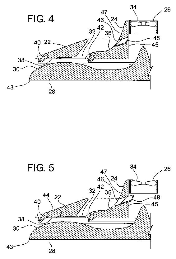


DETAILED DESCRIPTION OF THE PREFERRED EMBODIMENT
Details of illustrative embodiments of the invention are set forth herein. However, it is to be understood that the embodiments describe and exemplify an invention that may take forms different from the specific embodiments disclosed. Structural and functional details are not necessarily to be interpreted as limiting, but rather as a basis for the claims.
FIG. 1 shows a perspective view of a crane 20 containing the preferred embodiment of the present invention as applied to an aerial crane 20. FIG. 2 is a partial cross-sectional view of the crane 20 taken along the line indicated in FIG. 1. The crane 20 has a wing 22 and a coanda 24 extending radially around the airflow inducement mechanism 26. The wing 22 has a leading edge 21 and a trailing edge 23. The coanda 24 also has a leading edge 25 and a trailing edge 27. The airflow inducement mechanism 26 can be a prop or axial fan driven by an internal combustion engine, electrical motor, hydraulic motor, pneumatic motor or any other type of engine capable of providing mechanical force.
The body 28 of the crane 20 is located just below the wing 22 and the coanda 24. The top of the body 28 forms a curved surface 30. The traditional rigging equipment such as hooks, lines, winches, blocks and tackles (not shown) can be attached in the normal fashion to the bottom of the body 28 of the crane 20. There is an opening 32 located between the wing 22 and the coanda 24. The opening 32 extends radially around the outer edge of the coanda 24. The wing 22 and coanda 24 are secured to the body 28 by a series of structural members (not shown), which allow the air to flow with minimal resistance.
When the crane 20 is in use, the airflow inducement mechanism 26 causes a downward airflow as indicated by the arrows in FIG. 2. The air flows down through the center 34 of the crane 20 along the curved surface 30. Airflow through the opening 32 is induced by the airflow along the curved surface 30. The induced airflow causes air to travel down over the top surface 36 of the coanda 24. The air coming through the opening 32 causes the airflow from the center 34 to separate from the bottom side 38 of the wing 22 as it passes between the wing 22 and the curved surface 30. This separation prevents the pressure on the bottom side 38 of the wing 22 from dropping. If the pressure on the bottom side 38 of the wing 22 drops too drastically, it will counteract and cancel out the lift generated pressure drop due to the increased airflow adjacent to the curved surface 30.
The airflow from the opening 32 has a downward direction as it enters the airflow from the center 34. This downward direction helps laminate the airflow from the center 34 onto the curved surface 30. This causes the airflow from the center 34 to compress, thus doubling the mass of air flowing over the curved surface 30 of the body 28. This compression produces a venturi effect on the airflow between the curved surface 30 and the bottom side 38 of the wing 22, thus increasing the velocity of the airflow.
Lift increases exponentially with the increased velocity of the airflow through the system. The increase in the mass and the increase in the velocity created by this arrangement allow the crane 20 to create 29.6 pounds of lift per horsepower, compared to 5 to 12 pounds of lift per horsepower of a typical helicopter.
FIG. 3 is a perspective view of an alternate embodiment of the present invention. FIG. 4 is a cross-sectional view of the embodiment of the crane 20 shown in FIG. 3, taken along the line 4-4. The crane 20 shown in FIGS. 3 and 4 has a set of flaps 40 attached to the trailing edge 23 of the wing 22 and another set of flaps 42 attached to the trailing edge 27 of the coanda 24. The wing 22 and the coanda 24 are constructed of a series of wedge shaped sections 29 extending around to form a complete circle. Both sets of the flaps 40 and 42 are located in every other section 29 of the wing 22 and coanda 24. The alternating sections of flaps 40 and 42 are necessary to avoid interference of movement between adjacent flaps. These flaps 40 and 42 are operated and attached by any means typically known in the aircraft industry, such as solenoids, hydraulics, pneumatics, worm gears, gears, rack and pinions or other mechanical linkages. The flaps 40 and 42 allow the airflow over the curved surface 30 to be further restricted, as well as to direct the airflow. This control of the airflow through the flaps 40 and 42 can be used to cause lateral movement of the crane 20.
FIG. 5 shows yet another embodiment of the present invention which functions the same as the one shown if FIG. 4. The difference between the embodiment shown in FIGS. 4 and 5 is that the embodiment shown in FIG. 5 has a second interior flap 44 located along the trailing edge 23 of the wing 22. The interior flap 44 is pivotally attached to the wing 22. The exterior flap 42 is then pivotally attached to the interior flap 44. These flaps 42 and 44 are located in every other section 29 of the wing 22. Having the two flaps 42 and 44 provides better control in restricting and directing the airflow. It would also be possible to add additional flaps in series to the trailing edge 23 of the wing 22 or the trailing edge 27 of the coanda 24. It would also be possible to attach sets of one or more moveable flaps in series along the trailing edge 43 of the curved surface 30 to aid in the control of the airflow. These flaps or sets of flaps in series would have to be in every other section 29 of the curved surface to avoid interference with adjacent flaps just as done with the flaps on the wing 22 and coanda 24.
FIGS. 3, 4 and 5 show a set of bypasses 46 which allow air to pass through the coanda 24 from the interior surface 45 to the exterior surface 47. The bypass 46 provides additional control of the airflow for controlling lift, stability and maneuverability. Each bypass 46 is equipped with a gate 48 which is used to control the flow of air through it. FIG. 4 shows the bypass gate 48 in the closed position. FIG. 5 shows the bypass gate 48 in the open position. The gate can be slidingly or pivotally attached to the bypass 46. Other forms of articulated or moveable attachment would also work for attaching the gates 48. The gate 48 can be operated by any means commonly known in the art, including solenoids, hydraulics, pneumatics, worm gears or other mechanical linkages.
FIG. 6 shows the preferred embodiment of the present invention as applied to a propulsion system 50 for a vehicle 52. FIG. 7 shows a wheeled vehicle 52 with a propulsion system 50 behind a grill 49. However, it should be noted that the propulsion system 50 can also be used on watercraft, hovercraft or other types of vehicles.
The propulsion system 50 has a wing 54, a coanda 56 and a curved surface 58 similar to that found in the crane 20 shown in FIGS. 1 through 5. However, the wing 54, coanda 56 and curved surface 58 of the propulsion system 50 are laid out in a linear form versus the circular form seen in FIGS. 1 through 5. The propulsion system 50 has an opening 60 at the center with an airflow inducement mechanism 62. Note the layout of the wing 54, coanda 56 and curved surface 58 are similar to those parts of the crane 20 shown in FIGS. 1 through 5, i.e. there is an opening between the wing 54 and coanda 56 and a passageway along the curved surface 58 formed by the wing 54 and coanda 56 on one side and the curved surface 58 on the other side. As such, the wing 54, coanda 56 and curved surface 58 all operate in the same manner as that disclosed for the embodiment shown in FIGS. 1 through 5 to help generate a force to propel the vehicle 52. The wing 54 has a leading edge 51 and a trailing edge 53. The coanda 56 has a leading edge 55 and a trailing edge 57. Just as in the crane 20 application shown in FIG. 3, one or more flaps 59 can be attached to the trailing edge 53 of the wing 54, the trailing edge 57 of the coanda 56 and curved surface 58 of the propulsion system 50 to control the airflow and direction of thrust.
The propulsion system 50 can be rotatably mounted in the vehicle 52, as indicated by the arrows 64 in FIGS. 7, 8 and 9. When the propulsion system 50 is in front of the vehicle 52, it creates a forward propelling force comprised of the "lift" and thrust to help move the car in a forward direction. The propulsion system 50 creates a "lift" due to pressure differences created by the flow of air over the wing 54, coanda 56 and curved surface 58. Because the propulsion system 50 when in use is typically oriented so the wing 54, coanda 56 and curved surface 58 are vertical, the "lift" becomes a forward moving force. The thrust can be directed using the flaps 59, covers 66 and rotation of the propulsion system 50 to create a forward moving force. Likewise, the propulsion system 50 can be rotated to produce a force to lift the front end of the vehicle 52.
FIG. 7 shows a perspective view of a vehicle 52 with the propulsion system 50 rotatably mounted in front of the vehicle 52 behind a grill 49. Both ends of the propulsion system 50 can be fitted with a cover 66 which helps redirect the flow of the air as indicated by the arrows 68. The flow of the intake air is indicated by the arrows 70. FIG. 8 shows an exploded view of the vehicle 52 shown in FIG. 7. The grill 49 is removed to reveal the propulsion system 50. FIG. 9 shows a further exploded view of the vehicle 52 with a propulsion system 50. One half of the propulsion system 50 is exploded to the side to show the various parts, including the curved surface 58, the coanda 56, the wing 54 and the cover 66. These same components have corresponding components laid out in a mirror image of them on the other side of the air inducement mechanism 62.
AIRCRAFT INTERNAL WING AND DESIGN
An aircraft designed with three wings located on either side of the fuselage. The forward wing has a downward angle with a curved top and bottom surface. The upper wing is located towards the rear of the aircraft and above the forward wing. The lower wing is located below the upper wing and slightly forward. It is also located to the rear and below of the forward wing. The outer ends of all three wings come into contact at one point. The forward wing uses the Coanda effect to increase the airflow across the top surface of the bottom wing. The aircraft can be designed so that it is large enough to carry people and/or cargo, or to be small enough to be flown as a toy aircraft. The like design can use any type of aircraft engine commonly used today.; One embodiment of the aircraft has two turbines, shaft-coupled to a power source, located on either side of the forward end of the fuselage. Each engine has part of its thrust diverted through and directed by a plenum disposed internal of the coanda toward both sides of the fuselage so that an equal amount of thrust flows through the duct and over the wings on either side of the fuselage. This ensures equal lift on the coanda and both wings on either side of the fuselage in the event that one engine malfunctions.
TECHNICAL FIELD OF THE INVENTION
The present invention relates to a wing design for an aircraft. The wing design can be used on aircraft capable of carrying passengers and cargo as well as on model aircraft built and designed without the capability of carrying passengers or cargo to be flown for recreation. The present invention can be incorporated into a powered aircraft or glider.
BACKGROUND OF THE INVENTION
It is common knowledge that air pressure at a point on the surface of a moving object is a function of the velocity with which air streams over the surface at that point. Indeed, this principle is the basis for aircraft design; that is, it is common practice to shape the wings of an aircraft so that the velocity of air streaming over the top surface of each wing is greater than the velocity of air streaming over the bottom surface of the wing. This velocity differential, achieved by the contour of the wing, results in a pressure differential across the wing so that a net force, lift, is exerted on the wing to support the aircraft in flight.
Traditional modern day aircraft typically have a single wing located on either side of the fuselage of the aircraft. The airflow over these wings provides the lift required to raise the aircraft off of the ground. There is typically a tail located at the aft end of the fuselage with a vertical member and two horizontal members, one located on each side of the vertical member. The tail provides stability for the aircraft in flight. Also, the tail and the leading and trailing edge of the wing typically contain the control surfaces which are used to maneuver and turn the aircraft.
The present inventor has two prior patents relating to wing designs which diverge from the typical modern aircraft design. U.S. Pat. No. 4,568,042 ("the '042 patent") issued on Feb. 4, 1986 discloses an aircraft having a fuselage provided with an internal duct extending longitudinally therethrough to provide an internal wing for the craft, the internal duct having the forward end open for receiving an air stream therethrough and the aft end thereof open for discharge of the air stream therefrom, the internal contour of the duct being alterable in accordance with required operational conditions for the flight of the craft, and a plurality of control flaps and/or vanes provided at the aft end of the duct for providing operational controls for the craft in the manner of a more conventional external wing craft.
U.S. Pat. No. 4,579,300 ("the '300 patent") issued on Apr. 1, 1986 discloses how lift for an aircraft is provided by forming a longitudinal lifting duct therethrough, said lifting duct having a substantially planar roof and a longitudinally cambered floor. When the aircraft is driven forwardly, a stream of air enters and passes through the lifting duct and the contouring of the floor of the lifting duct give rise to a pressure gradient in the air stream which result in a higher pressure on the roof of the lifting duct than on the floor thereof so that the pressure difference provides lift for the aircraft.
The drawback to the aircraft design found in the '042 and '300 patents is that the aircraft had little wing span. This in turn meant that the aircraft had less desirable gliding range in the event of loss of power.
The present invention also provides a structurally much stronger wing configuration than a traditional aircraft wing design with a single wing protruding transverse to the longitudinal axis of the fuselage.
BRIEF SUMMARY OF THE INVENTION
The applicant has come up with an improved aircraft design. The aircraft has three wings and uses the Coanda effect to increase the lift available on the wings for a given speed. It also has an improved aspect ratio over the aircraft disclosed in the '042 and '300 patents and therefore provides better glide capabilities.
It is to be understood that both the foregoing general description and the following detailed description are exemplary and explanatory only, and are not restrictive of the invention as claimed. The accompanying drawings, which are incorporated herein by reference, and which constitute a part of this specification, illustrate certain embodiments of the invention and, together with the detailed description, serve to explain the principles of the present invention.
In this respect, before explaining at least one embodiment of the invention in detail, it is to be understood that the invention is not limited in this application to the details of construction and to the arrangement so the components set forth in the following description or illustrated in the drawings. The invention is capable of other embodiments and of being practiced and carried out in various ways. Also, it is to be understood that the phraseology and terminology employed herein are for the purpose of description and should not be regarded as limiting. As such, those skilled in the art will appreciate that the conception upon which this disclosure is based may readily be utilized as a basis for the designing of other structures, methods and systems for carrying out the present invention. It is important, therefore, that the claims be regarded as including such equivalent constructions insofar as they do not depart from the spirit and scope of the present invention.
Further, the purpose of the foregoing abstract is to enable the U.S. Patent and Trademark Office and the public generally, and especially the design engineers and practitioners in the art who are not familiar with patent or legal terms or phraseology, to determine quickly from a cursory inspection the nature and essence of the technical disclosure of the application. The abstract is neither intended to define the invention of the application, which is measured by the claims, nor is it intended to be limiting as to the scope of the invention in any way.
The present invention has a design which takes advantage of the Coanda effect. The Coanda effect causes fluids which are flowing over a curved surface to continue to follow the curvature of that surface. The Coanda effect is best demonstrated by holding a curved surface such as the side of a glass under a running stream of water. As the glass is held on its side, the water falls onto the top side of the glass and will encircle the glass as it flows over its circumference.
The present invention has three wings located on either side of the fuselage. The outer edge of all three wings are joined together. The leading wing or coanda is mounted forward of the upper and lower wing. The coanda has a downward sloping angle with a curved top and bottom surface. The upper wing is mounted higher on the fuselage and towards the rear in relation to the coanda. The lower wing is mounted below and slightly forward of the upper wing. The lower wing is also below and to the rear of the coanda. The upper surfaces of the upper wing and the lower wing are curved while the undersides of both the upper and lower wings are generally flat. This provides lift when the aircraft moves in the forward direction.
The coanda takes advantage of the Coanda effect and pulls more air over the lower wing. This increases both the density of the air flowing over the lower wing as well as the velocity across it. This in turn helps increase the lift.
The coanda helps create a split flow between the upper and lower wings creating a boundary layer separation from the bottom of the top wing and adhesion of the airflow to the wing resulting in a low pressure area just above the lower wing and a high pressure area below the upper wing. The upper and lower wings also create a venturi which also adds to the low pressure just above the lower wing. The jet-pumping action induced by the contours enhance thrust, lift and general stability. The synergistic effect of the coanda and the upper and lower wings induces a centrifugal flow component that provides additional stability for the aircraft.
The centrifugal flow component creates a pair of vortices, one under both of the upper wings. These vortices rotate in a counter-clockwise direction when looking from the end of the wings towards the fuselage of the plane. The location of the vortices varies as a function of the speed of the aircraft forward. As the speed of the aircraft increases, the vortices tend to move in an aftward direction underneath the upper wing. In alternate embodiments of the present invention, a Kruger flap can be installed on the bottom side of the upper wing just aft of the leading edge. By extending the Kruger flap or opening the Kruger flap, the location of the vortices can be moved forward.
The aircraft can be controlled by conventional control surfaces found on the coanda, the upper and lower wings, as well as the tail. In an alternative embodiment, the aircraft can be controlled by a variable camber aero hydronamic surface (VCAHS). The VCAHS is a series of collapsible and expandable honeycomb chambers located on the surface of the wings. These are coupled to a pressure manifold and a vacuum manifold. A flexible surface would then be used on top of the VCAHS to provide the outer surfaces of the coanda and upper and lower wings. The contour of the surfaces could then be altered to adjust the high and low pressure areas around the wings and provide control of the aircraft. This reduced the drag inherent with convention control surfaces.
The present invention can be used on aircraft designed to passengers and cargo as well as model or toy aircraft designed to be flown as recreation or a hobby. Such model or toy aircraft are typically launched by throwing them by hand or in the alternative by powering them with a small remote controlled motor or engine.
The present invention, when coupled with a jet propulsion system, can be capable of short takeoff and landing performance (STOL). This can be achieved by opening the saddle shunt just aft of the engines so that the thrust coming off of the engines flows across the coanda and upper and lower wing surfaces while a pair of thrust diverters located on either side of the aft end of the fuselage divert the thrust. Once airborne, the thrust diverters can be retracted so that the thrust coming across the coanda and wings of the aircraft provide a forward thrust. When the aircraft reaches the desired altitude, the saddle shunts can then be closed so that the thrust from the engines flows through the duct work located in the fuselage out the rear of the aircraft.
Additional objects and advantages of the invention are set forth, in part, in the description which follows and, in part, will be apparent to one of ordinary skill in the art from the description and/or from the practice of the invention.
These together with other objects of the invention, along with the various features of novelty which characterize the invention, are pointed out with particularity in the claims annexed to and forming a part of this disclosure. For a better understanding of the invention, its operating advantages and the specific object attained by its uses, reference would be had to the accompanying drawings, depictions and descriptive matter in which there is illustrated preferred embodiments and results of the invention.
DESCRIPTION OF THE DRAWINGS
FIG. 1 is a front perspective view of an aircraft incorporating the present invention.
FIG. 2 is a lower rear perspective view of an aircraft incorporating the present invention.
FIG. 3 is an upper rear perspective view of an aircraft incorporating the present invention.
FIG. 4 is a left side view of an aircraft incorporating the present invention.
FIG. 5 is a top view of an aircraft incorporating the present invention.
FIG. 6 is a front view of an aircraft incorporating the present invention.
FIG. 7 is a rear view of an aircraft incorporating the present invention.
FIG. 8 is a perspective view of the variable camber aero hydrodynamic surface (VCAHS).
FIG. 9 is a cross-sectional view of an upper wing with a VCAHS surface.
FIG. 10 is a top view showing the ducting of an aircraft incorporating the present invention along with the preferred embodiment of the power configuration.
FIG. 11 is a side view showing the ducting of an aircraft incorporating the present invention along with the preferred embodiment of the power configuration.
FIG. 12 is a sectional side view of the saddle shunt in the open position.
FIG. 13 is a sectional side view of the saddle shunt in the closed position.
FIG. 14 is a top view of an aircraft incorporating the present invention and using conventional control surfaces.
FIG. 15 is a side view of an aircraft incorporating the present invention and using conventional control surfaces.
FIG. 16 is a cross-section view of the port side wings with arrows indicating the air flow.
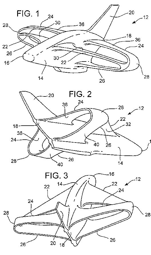


DETAILED DESCRIPTION OF THE INVENTION
While the making and using of various embodiments of the present invention are discussed in detail below, it should be appreciated that the present invention provides for inventive concepts capable of being embodied in a variety of specific contexts. The specific embodiments discussed herein are merely illustrative of specific manners in which to make and use the invention and are not to be interpreted as limiting the scope of the instant invention.
The claims and specification describe the invention presented and the terms that are employed in the claims draw their meaning from the use of such terms in the specification. The same terms employed in the prior art may be broader in meaning than specifically employed herein. Whenever there is a question between the broader definition of such terms used in the prior art and the more specific use of the terms herein, the more specific meaning is meant.
While the invention has been described with a certain degree of particularity, it is clear that many changes may be made in the details of construction and the arrangement of components without departing from the spirit and scope of this disclosure. It is understood that the invention is not limited to the embodiments set forth herein for purposes of exemplification, but is to be limited only by the scope of the attached claim or claims, including the full range of equivalency to which each element thereof is entitled.
An aircraft incorporating the present invention is shown from various angles in FIGS. 1 through 7. The aircraft 12 has a fuselage 14 with a forward end 16 and an aft end 18. There is a tail 20 located on the aft end 18 of the fuselage 14. There are three wings located on either side of the fuselage 14. The forward wing or coanda 22 is located towards the forward end 16 of the fuselage 14. The upper wing 24 is located up and towards the aft end 18 of the fuselage 14 in relation to the coanda 22. The lower wing 26 is located below the upper wing 24 and slightly forward. The lower wing 26 is located below and toward the aft end 18 of the fuselage 14 in relationship to the coanda 22. The coanda 22, upper wing 24, and lower wing 26 are all connected at one point at their outer end 28.
The coanda 22 is attached to the fuselage so that it has a downward rear angle. The top and bottom surfaces 30 and 32 of the coanda 22 are curved. Due to the Coanda effect, the air flowing over and under the coanda 22 will follow the curve of the top and bottom surfaces 30 and 32 of the coanda 22 and then flow across the top surface 34 of the lower wing 26.
The top surfaces 34 and 36 of the lower and upper wings 26 and 24 are curved while the bottom surfaces 38 and 40 of the upper and lower wings 24 and 26 are generally flat. The increased airflow across the top surface 34 of the lower wing 26 due to the coanda 22 helps increase the density and velocity of the airflow across the top surface 34 of the lower wing 26. This in turn helps increase the lift generated by the lower wing 26. In addition, the upper wing 24 also generates lift.
The aircraft can be maneuvered and controlled by manipulating control surfaces found on the coanda 22, upper wing 24, lower wing 26 and tail 20. These are the types of control surfaces which are well known in the art.
In an alternate embodiment, the aircraft can be maneuvered by changing the contour of the surfaces of the coanda 22, upper wing 24 and lower wing 26. FIG. 8 is a perspective view of the variable camber aero hydrodynamic surface (VCAHS) 42. The VCAHS 42 is made up of a plurality of flexible cells 44. Each cell 44 is connected to a vacuum header 46 and a pressure header 48 via a vacuum line 50 and a pressure line 52, respectively. The top and bottom surfaces 30 and 32 of the coanda 22, the top surface 34 of the lower wing 26, the top surface 36 of the upper wing 24, and the bottom surface 38 of the upper wing 24, and the bottom surface 40 of the lower win 26 can be covered with the VCAHS 42. The contour of these surfaces can then be adjusted by controlling the flow to and from the VCAHS cells 44. By adjusting the vacuum valve 54 and pressure valve 56 found on each VCAHS cell 44, the change in the contour of the surfaces can then be used to maneuver aircraft 12. This enables the aircraft 12 to be maneuvered without creating any drag inherent with conventional controlled surfaces.
FIG. 9 is a cross-sectional view of an upper wing 24. The top surface 36 and the bottom surface 38 of the upper wing 24 are covered with a plurality of VCAHS cells 44. Each of the VCAHS cells 44 are connected to the vacuum manifold 46 via a vacuum line 50 and the pressure manifold 48 via a pressure line 52. It should be noted that not all of the vacuum lines 50 and pressure lines 52 are shown in FIG. 9, in order to provide a more understandable drawing. The coanda 22 and the lower wing 26 can also be covered by the VCAHS 42. The contour of the upper wing 24, as well as the coanda 22 and the lower wing 26, can then be altered by changing the air pressure in the VCAHS cells 44 using the vacuum and pressure from the vacuum manifold 46 and pressure manifold 48. Not all of the vacuum lines 46 and pressure lines 48 are shown in FIG. 9, in order to provide a more legible drawing.
The present invention can be incorporated into an aircraft which is propelled by any type of power plant commonly used or known in the art. This power plant can be mounted on the forward end 16 of the fuselage 14, the tail 20, or any one or more of the wings 22, 24 and 26, as well as on the fuselage 14. The one configuration would be to mount an engine and propeller on the forward end 16 and/or the tail 20. Likewise, the present invention can be incorporated into an aircraft which is a glider. Another embodiment of the present invention is to use it on an aircraft capable of carrying passengers and/or cargo. Yet another embodiment of the present invention is to use it on a model or toy airplane or glider of the type typically flown for recreation or as a hobby.
FIG. 10 provides a top view of the preferred engine configuration. FIG. 11 provides a side view of the engine configuration found in FIG. 10. There is an engine 58 provided on either side of the fuselage 14. Each engine 58 would preferably be a turbo, however, other types of engines known in the art could be used. Each engine 58 has a saddle shunt 60 located just behind the outlet of the engine 58. The saddle shunt 60 is attached to the fuselage 14 by a hinge 61. When the saddle shunt 60 is in the open position, as shown in FIG. 12, the thrust 63 from the engines 58 flows through the through fuselage bypass duct 62 and out the aft end 18 of the aircraft 12. When the saddle shunt 60 is in the closed position, as shown in FIG. 13, the thrust 63 from the engines 58 are each diverted so that they run through the crossover duct 64 and the coanda duct 65. The thrust 63 running through the coanda duct 65 exits the coanda duct 65 through an opening 67 near the trailing edge of the coanda 22 on the same side of the fuselage 14 as the engine 58 that generated the thrust 63. The portion of the thrust 63 from each engine 58 running through the crossover ducts 64 crosses to the opposite side of the fuselage 14 from the engine 58 that generated the thrust 63. The thrust 63 from the crossover duct 64 is then injected into the coanda duct 65 where it mixes with the thrust 63 from the opposite engine 58 and exits out the opening 67 in the coanda 22 on the opposite side of the fuselage 14. This helps provide an even lift on either side of the fuselage 14 in the event that one of the engines 58 is lost or malfunctions.
The engine configuration shown in FIGS. 10 and 11 would be capable of a short takeoff or landing (STOL). In order to do that there is a pair of thrust reversers 66 located on either side of the tail 20 of the fuselage 14. FIG. 10 shows the top view of the aircraft 12 with the thrust diverters 16 in the extended position. FIG. 11 shows a side view of the aircraft 12 with the thrust diverters 66 in the retracted position. In order to perform a short takeoff or landing, the saddle shunt 60 would be in the closed position as shown in FIG. 13. This would divert the thrust from the engines 58 so that it ran through the crossover duct 64 and coanda duct 65, out the openings 67 near the trailing edge of the coandas 22 and over the top surface 34 of the lower wing 26. The thrust would then be diverted by the thrust diverters 66 located on either side of the aft end 18 of the fuselage 14. This allows the engines 58 to create the lift necessary to lift the aircraft 12 off the ground with limited forward movement. Once the aircraft 12 was at the desired altitude, the thrust diverters 66 could be retracted into the position shown in FIG. 11 to increase the forward movement of the aircraft 12.
FIG. 14 shows a top view of an aircraft 12 incorporating the present invention in use with conventional control surfaces 68 in lieu of using the VCAHS 42 control surfaces. FIG. 15 shows a side view of an aircraft incorporating the present invention and using conventional control surfaces 68. It should be noted that the location of the control surfaces 68 shown in FIGS. 14 and 15 are not the sole control surfaces that could be adapted to the aircraft 12. The present invention could include a number of other conventional control surface designs.
FIG. 16 is a cross-sectional view of one embodiment of the present invention taken along a line indicated in FIG. 14. It has been simplified by not showing any of the internal structures of the coanda 22, upper wing 24 or lower wing 26. FIG. 16 shows the location of the regions of high pressure 102, the low pressure 104, and the vortex 106. As the airspeed of the aircraft 12 increases, the location of the vortex 106 migrates aftward underneath the upper wing 24. This causes change in the location of the high pressure under the wing and could affect the handling of the aircraft 12. Vortex 106 further compresses the air between the vortex 106 and the upper wing 24, thus increasing the density of the air in that region and the lift generated by the upper wing 24.
FIG. 16 also shows one embodiment of the invention, that being a Kruger flap 108 located on the bottom surface 38 of the upper wing 24 just aft of its leading edge. The Kruger flap 108 can be open or extended as shown in FIG. 16 to move the vortex 106 forward in relationship to the aircraft 12. This may be necessary to help the handling characteristics of the aircraft 12.
It will be apparent to those skilled in the art that various modifications and variations can be made in the construction, configuration, and/or operation of the present invention without departing from the scope or spirit of the invention. For example, in the embodiments mentioned above, variations in the materials used to make each element of the invention may vary without departing from the scope of the invention. Thus, it is intended that the present invention cover the modifications and variations of the invention, provided they come within the scope of the appended claims and their equivalents.