System for Controlling a Rotary Device
The Cairns Post(3-8-01)
The Inventors
How It Works
Lutec Skeptics Challenged
Lutec Newsletter (Vol.
1(1), February 2002)
WIPO Application # WO 00/28656
Adams vs Lutec
Rosenthal Measurements
"New Magnetic-Electric Device Offers Near
Free Energy Source"
by
Penny Robins
The Cairns Post (Northern
Queensland, NZ ~ 3-8-01)
Two Cairns inventors yesterday unveiled a world first commercial machine which can power a house from a permanent, clean, green and virtually free energy source. The machine, developed by Brinsmead mechanical engineer John Christie and Edge Hil electrician Lou Brits, has an international patent pending and is expected to go on the market for $4000-$5000.
Relying on the attraction and repulsion of internal magnets, the Lutec 1000 operates continually on a pulse-like current 24 hours a day - producing 24 kilowatts of power - once it is kickstarted from a battery source. The device is more than 500 per cent efficient, compared to a car which is less than 40 per cent efficient and loses power through heat and friction. No powerlines would be needed to distribute energy from the individual power sources. There is no heat, harmful emissions or airborne matter in the transmission. If it were not for the magnets, which have a life of 1300 years, and the battery pack, which has a life of about five years, the machine would be in perpetual motion.
A demonstration of the motor from the carpeted study of Mr Christie's Brinsmead home revealed the device in all its glory - bigger than the average cyclone back-up generator but much less noisy. M Christie and Mr Brits have been tinkering together on the motor in their spare time since they met in a Sheridan St cafe five years ago and began sharing ideas. One and a half years ago, the design was perfected and the pair lodged a patent with Brisbane patent attorneys Griffith Hack. Mr Christie said the next step was to develop a small-scale pilot plant in Cairns to begin distributing the motors to the places they were needed most - such as shops and homes in the power-starved Daintree region and the Torres Strait. He said the price tag for the devices could vary in remote locations depending on government rebates, freight and installation costs.
The beauty of the device was that it was transportable and could be packed in a removalist van along with other earthly possessions when moving house, he said The only problem the pair now face is in raising $500,000 to start their production plant. "We're trying to keep it local, and trying to keep it in Australia, but it's hard because, offshore, they are more aggressive in taking up new initiatives," Mr Christie said.
Already, the invention has received interest from the United States, China, Japan and Indonesia. "But we want to set up here and put the product on the market first, and then we'll take it to the world," he said. Mr Christie said it had been hard to keep a lid on the invention which had such a huge potential in the quest for clean, green, energy production. He said he and Mr Brit also feared the worst once they realised the significance of their invention. "We were afraid the kids would be kidnapped or we'd be shot, I'm not kidding," he said. "You hear horror stories about people running up against fuel companies, but it's all hogwash --- people in the main are desperately looking for technologies that will help our environment."
The pair have begun discussions with Ergon [ the local electricity supplier utility] as there is also the opportunity of selling energy back to the grid. Mr Christie said the average home with a pool needed only 14kW of energy per day - which meant a 10 kW daily excess would be left over during the generation process
Griffith Hack partner Cliff Carew, who was speaking from Brisbane, confirmed the device was genuine and unique. "An international application has been lodged, they've conducted an international search and haven't come up with anything similar, so it would seem to be a new concept," Mr Carew said. He said it would be another two and a half years before the patent was recognised in 140 countries around the world - the usual length of time for an international patent to be processed.

Lou Brits
(left) and John Christie
The Cairns Post ~ Two Cairns inventors who say they have developed a radical new energy generating machine have been swamped with inquiries over the past 24 hours since going public with their discovery.
He
was among a crowd of curious Far Northerners who rushed to
contact Edge Hill electrician Lou Brits and Brinsmead
mechanical enginner John Christie once news of their
invention broke in the Cairns Post yesterday.
Investors,
people with scientific backgrounds and those who were keen
to buy one of the new Lutec 1000 machines to power their
homes swamped the Cairns Post and the two inventors, who
work from home, with their calls. The generator is capable
of producing 24 kilowatts of energy per day and is powered
by the alternating attraction and repulsion of internal
magnets once it is kickstarted from a battery source.
It has more than twice enough energy to power the average family home, while remaining free from heat, emissions or airborne matter. Mr. Christie said he and Mr. Brits realised their invention "flew in the face of physics" by being 500 per cent efficient - but it worked.
"The phone hasn't stopped ringing." Mr. Christie said yesterday afternoon. We've had calls from the Daintree - people wanting to place orders and buy them. We're happy about that but, really, we're not in the position to take orders."
Mr. Christie said he began receiving phone calls from 7:30AM yesterday (when the story was first reported).
Mr. Christie said people begain arriving unannounced on his doorstep from 8:30AM.
He said two people he had never met before had even needed to be ushered out of the room just after 9AM when he went on air for a radio interview.
An international patent is pending on the invention and the two men already have received interest from overseas.
But Mr. Brits and Mr. Christie say they are keen to setup a production plant in Cairns to produce the machines on a small scale to power homes in remote areas of Queensland like the Daintree region and in the Torres Strait.
Cairns businessman Alex Roma yesterday said he was prepared to help bankroll the production plant as it was an opportunity to expand industry in the Far North.
Ahead of meeting the two inventors late yesterday, Mr. Roma said if their invention stacked up, he was prepared to up up "a large sum" to help make the local production plant a reality.
"Looking at this, it's fantastic," he said. "I've always said Cairns needs a boost in industry - it's one thing Cairns is lacking. We'd employ local people and produce something we could export apart from sugar cane and seafood."
Mr. Roma said an opportunity existed to produce locally not just the machines but all of the accompanying components.
Member for Leichhardt Warren Entsch lent his support to the proposal to develop a plant to manufacture the clean, green power generators in Cairns.
Ergon Energy spokeswoman Sara Collins said discussions were ongoing with the inventors, who hope to sell excess power back to the grid.


John
Christie (left) is the co-founder, CEO and chairman of
Lutec (Aust.) Pty Ltd.
Education:
Auckland Technical Institute, Mechanical Engineer.
He has a vast experience in operating small businesses, is on the boards of FNQ Outreach Limited and Trinity Care Association, and is a director of Technology Trading International Pty., Ltd.
His business history includes introducing light steel framed building systems into North Qld., Co-Designing and patenting a new light steel frame construction system subsequently sold to the US.
He co-designed, developed, and made patent application for a new form of wind turbine.
He was Managing Director of Tarinfile Pty., Ltd., the owner of True Blue Sheds a successful North Qld company specialising in manufacturing, marketing and selling steel framed farm buildings, and low cost housing mainly to rural and remote communities.
He has also held middle management positions with the Australian Broadcasting Commission.
Ludwig (Lou) Brits (right, above) is the co-founder, managing director and head of development of Lutec (Aust.) Pty., Ltd.
He is Chairman and director of TTI Pty., Ltd. TTI Pty Ltd is a state government recognised R.A.P. (remote area power) system provider.
Education: Mechanical and electrical engineering and trade certificates (Europe).
Mr Brits has had a varied international career including running hydro electric power stations, designing and manufacturing various electrical components for power stations. Maintaining power stations.
He is an inventor of many and varied objects and products including a wind powered turbine system, electronic health care products, water treatment systems, and hydro/organic fertilizing/pest control products.
He has a wealth of talent and inventive genius, and is well regarded and highly respected by those he works with.
We have never said there is an "endless" source of energy emanating from magnets. We have said that the magnets we use in the Lutec 1000 are able to maintain their magnetic qualities for over twelve hundred years. That is a long time when gauged by human life expectancy, but is not forever. We welcome informed opinion, and to that end have sought out the highest qualified people in Australia and the United States of America to review our work.
The Lutec 1000 only baffles those who misinterpret the actions taking place within it as being outside common scientific principles and laws, where in fact it certainly is not. We will try to make a simple explanation to demonstrate what motivates the Lutec 1000 motor/ generator:
Let’s say we hang a ten kilo weight off a permanent magnet butted to a steel roofing beam, and that the only thing holding the permanent magnet to the steel beam is the magnetism. Now let’s do the same thing, but this time with an electro-magnet which requires a constant electrical input to maintain its magnetic qualities.
Let’s say we leave them both there for ten years"
They will both perform the same task, that of holding the ten kilos off the floor. The electro-magnet, however, has needed to be fuelled by electricity provided by a generator of some kind - it could be hydro, nuclear, wind, solar, coal or oil - and has cost a large amount in terms of energy. Much work (in the scientific sense) has been done to provide the constant electric current necessary to maintain its magnetic hold on the steel girder.
Now take notice, the permanent magnet has not needed to be energised by an external source, it has done the job for free" using only the magnetism it contains to perform the same job. The clue here is in the title of "permanent" magnet.
That same principle is one of the reasons the Lutec 1000 motor turns, it is of course the spinning of the centre core of the motor which is caused by the permanent magnets being attracted and then repulsed from the steel cores of the fixed stator coils. It is this primary movement that allows the magnetic fields around the stator coils to be "cut" by the effect of the permanent magnets sweeping past the steel cores of the coils.
Note that we have achieved two effects from one cause, thus inducing an electric current per Mr Faraday’s theory, and so generating electricity as an output or product of the motors motion. The only electricity consumed has been that required to temporarily charge the coils and so creating a temporary magnet of like polarity to cause the permanent magnet to be repulsed rather than attracted.
There are a couple of other major factors that we won’t go into here, suffice it to say that our current prototype demonstrates 1500% more "out" than "in"...
For the technically-minded, the following formula is used to determine consumption of input power:
If the waveforms are periodic with constant rotational speed of the machine and constant mechanical load on the output, then a calculation of energy usage over one full rotational cycle should suffice. Along with all previous assumptions remaining valid, the formula then becomes:
(where W(T) represents the net energy usage in joules over one period T).
Inventors of the controversial Lutec fuel-free energy generator have thrown off the machine's cover and invited sceptics to air their doubts when the generator is publicly displayed later this year.
The Lutec 1000 has been refined and redeveloped for the sixth time and inventors Lou Brits and John Christie say the machine is almost ready for release. They are also inviting qualified electricians to personally contact them about becoming licensed installers for the Cairnes area.
The sixth generation Lutec 1000 now stands one metre tall (in an upright position) and has a steel frame which has allowed the inventors to attach more magnets closer to the drum to increase the power generation capacity.
Mr. Christie said the 'switches' used to supply the energy into the drum-shaped machine were also becoming smaller and more compact.
The new-look Lutec should be completed by the end of the month and the inventors hope to display all six generations of the machine at the Hilton Hotel later this year.
While Mr. Christie is eager to silence the critics with a public demonstration, he must wait for international agreements to be finalized.
However, he did invite the 'doubters' to see the machine work in person, saying patents were now pending in more than 100 countries, and he could provide detailed information of experts who could verify their work.
'They are welcome to contact us and we will give them the names of experts who have assessed the machine, but who's going to pay the experts, who are paid more than $US90 an hour, to sit down and explain it to them - because we're not,' Mr. Christie said.
'We don't mind people criticising the machine, but no one who has come to see the motor has gone away still believing it would not work.'
Mr. Brits said the crux of the disbelief centred around the perception that the Lutec 1000 created energy - an assumption which was essentially flawed.
'They are not taking into account the combination of the capabilities of permanent magnets and the effects on the incoming current caused by the induction of a greater current caused within the motor,' he said.
'All people see is the amount of energy we are putting in and more coming out. They then wrongly assume that we are creating energy.'
The core of the Lutec 1000 spins as the magnets - spaced alternately around the drum - are attracted then repulsed (using a small electrical circuit) to steel cores which are off-set above the centre down.
Mr. Brits said the machine released the energy stored in the magnets and anyone who doubted the 'stored energy' should try holding a piece of steel off the ground for an extended period.
'In the same way as a person holding a weight uses energy while they are not moving, a magnet uses energy to attract and hold a piece of steel,' he said.
'And it's absolute nonsense that a magnet can only be used on once. Everybody knows if you take a fridge magnet off the fridge and put a new piece of paper under it, it still sticks as good as new.'
A recent demonstration showed the inventors were modest in claiming a 400 per cent increase in energy output, with the Lutec 1000 lighting up six light bulbs (360 watts) with an input of just 42 watts.
Mr. Brits admitted the magnets would run out of 'energy', in approximately 1300 years, but could be recharged with an electrical current.
Mr. Christie said he and Mr. Brits had recently been approached by a company whowere interested in adapting the Lutec to power machines used in space exploration and he believed eventually the generator could be used in motor operated appliances.
The Environmental Protection Agency had also assessed the machine with the intention of giving inertial household users rebates or 'green house credits'.
He said the size and capability of the machine could be changed to suit the need and envisioned a household full of Lutec 1000's.
'Things like your fan could have a Lutec motor and the excess energy created could go back into a household battery to run static appliances like your television.
'It is certainly possible that it could remove a household from the power grid completely.'
For more information visit the website at:
It has been almost a year since many of you first registered your interest in the Lutec technology phenomenon. We apologize for the long delay in preparing this much awaited newsletter. We can only say that we share your frustrations as the past year has been mainly spent trying to source venture capital to get the Lutec revolution underway.
Sadly, we have to report that it is almost impossible to obtain financial support for a "green fields" technology based on new technology in Australia.
However, the year has not been wasted by any means. Lou and John have continued development of the Lutec 1000. The solid state switching has been designed, built, tested and installed onto the machine with the results to output exceeding expectations. The machine itself has also undergone a number of design refinements which ahve all added to improved efficiency.
Finally I can report that the manufacture of these generators has been awarded to a Cairns electrical manufacturer with prodcution expected to start by the end of this financial year. Initially the rate of production will be limited to only 10 per month, but we expect to increase this to 250 per month as demand and capital allow.
We hope to have one of the new Lutec 1000 electrical generators on permanent public display commencing from the end of April.
For those of you waiting for the opportunity to acquire one of these electrical generators, please act quickly as weexpect demand to far outweigh supply and the waiting period for delivery may be as much as 6 months.
Fortunately the international interest in this new revolutionary technology far exceeds the apathetic approach shown by Australian entrepreneurs.
We can now report that a licensing agreement is now in place for the manufacture and sale of the Lutec technology within America.
Negotiations for the rights to Southeast Asia and Europe are ongoing with a number of interested companies and we expect these to be finalized by the end of 2002.
It is only this interest which has allowed Lutec Australia to commence operations.
( Equivalent: US Patent # 6, 620,806 issued October 7, 2003 )
World
Intellectual Property Organization
International
Application # WO 00/28656
Publication
Date: 18 May 2000
International
Application # PCT/AU99/00962
Applicants & Inventors:
BRITS,
Ludwig (3/13 Springfield Crescent, Whitfield, Cairns,
QLD 4870 Australia)
CHRISTIE,
Victor John (7/34 Springfield Crescent, Whitfield,
Cairns, QLD 4870 Australia)
Agent: Griffith Hack, GPO Box 3125,Briscbane, QLD 4001, Australia
Abstract --- A system for controlling a rotatable device, the system comprising a controller and a rotary device, which has a stator and rotor, wherein the controller is connected to the rotary device to control rotation of the rotary device, and wherein the controller is adapted to periodically energize at least one energizing coil of the device to create a magnetic field of a polarity which induces the rotor to rotate in a single direction and wherein the controller is switched off so as to de-energize the energizing coil when other forces, being forces other than those resulting from the energized energizing coil, produce a resultant force which induces rotation of the rotor in the single direction.
Field of Invention
The present invention relates to motors which are used for generating a torque and generators used for generating electricity.
Background of the Invention
A typical electric motor consists of a stator and rotor.
The operation of an electric motor is based on the principal that an electric current through a conductor produces a magnetic field, the direction of current in an electromagnet such as a coil of wire determines the location of the magnet poles and like magnetic poles repel and opposite poles attract.
The stator which is typically called the field structure establishes a constant magnetic field in the motor.
Typically the magnetic field is established by permanent magnets which are called field magnets and located at equally spaced intervals around the rotor.
The rotor or armature typically consists of a series of equally spaced coils which are able to be energized to produce a magnetic field and thus north or south poles.
By keeping the coils energized the interacting magnetic fields of the rotor and the stator produce rotation of the rotor.
To ensure that rotation occurs in a single direction a commutator is typically connected to the windings of the coils of the rotor so as to change the direction of the current applied to the coils.
If the direction of the current was not reversed the rotor would rotate in one direction and then reverse its direction before a full cycle of rotation could be completed.
The above description typifies a DC motor. AC motors do not have commutators because alternating current reverses its direction independently.
For a typical AC motor such as an induction motor the rotor has no direct connection to the external source of electricity. Alternating current flows around field cols in the stator and produces a rotating magnetic field. This rotating magnetic field induces an electric current in the rotor resulting in another magnetic field.
This induced magnetic field from the rotor interacts with the magnetic field from the stator causing the rotor to turn.
An electric generator is effectively the reverse of an electric motor. Instead of supplying electricity to coils of either the stator or the rotor, the rotor or armature is rotated by physical forces produced by a prime mover.
In effect a generator changes mechanical energy into electrical energy.
Summary of the Invention
The present invention is aimed at providing an improved rotary device which operates with improved efficiency compared to conventional rotary devices.
The present invention is also concerned with providing a system for controlling a rotary device which is able to generate electrical and/or mechanical energy.
According to the present invention there is provided a system for controlling a rotary device, the system comprising a controller and a rotary device, which has a stator and rotor, wherein the controller is connected to the rotary device to control rotation of the rotary device, and wherein the controller is adapted to periodically energize at least one energizing coil of the device to create a magnetic field of a polarity which induces the rotor to rotate in s single direction and wherein the controller is switched off so as to e-energize the energizing coil when other forces, being forces other than those resulting from the energized energizing coil produce a resultant force which induces rotation of the rotor in a single direction.
Preferably the controller is adapted to energize the energizing coil for a period which the resultant force from the other forces acts to rotate the rotor in the opposite direction, whereby the force applied by the energizing coil overcomes (is greater than) the resultant force.
The controller is preferably adapted to switch off to de-energize the energizing coil before the resultant force is zero.
The controller preferably is adapted to switch off to de-energize the energizing coil for a period before the resultant force is zero, and to allow back EMF induced by other forces to urge the rotor to rotate in the single direction before the resultant force is zero.
Preferably the resultant force excludes forces arising from back EMF.
The energizing coil may be adapted to be energized by the controller through a predetermined angle of a complete revolution of the motor.
Preferably the/each energizing coil is energized more than once during a single revolution (cycle of the rotor.
The/each or at least one energizing coil may be energized each time the resultant force applies a force to the rotor in the opposite direction.
The/each or at least one energizing coil may be energized by a periodic pulse applied by the controller.
The periodic pulses are preferably all of the same sign.
The/each or selected ones of the energizing coils are energized whenever the resultant force is in the opposite direction and then for a period less than the period during which the resultant force changes from zero to a maximum and back to zero.
According to one embodiment the stator has the at least one energizing coil.
The rotor may have at least one magnetic field generating means which is able to generate a magnetic field which interacts with the magnetic field generated by the/each energizing coil when energized, to apply a force to rotate the rotor in one direction.
The/each energizing coil preferably includes a magnetic interaction means which is adapted to either repel or attract the magnetic field generating means.
The magnetic interaction means may comprise a ferrous body or body of another substance which is attractable to a magnetized body.
The magnetic field generating means may be a permanent magnet.
The magnetic interaction means may be an iron core or a permanent magnet.
Preferably the magnetic field generating means comprises a permanent magnet, or member attractable to a magnetized body.
The stator preferably comprises a plurality of energizing coils evenly spaced around the rotor.
Each energizing coil is preferably an electromagnet.
Preferably the or each energizing coil includes the magnetic interaction means through its coil.
Preferable the rotor comprises a plurality of evenly spaced magnetic field generating means.
According to one embodiment the rotor comprises a plurality of evenly spaced permanent magnets.
The evenly spaced permanent magnets may all be of the same polarity.
The evenly spaced magnetic field generating means may be energizable coils simulating magnets.
Preferably the poles of the magnetic field generating means are all the same.
The magnetic poles produces by energized energizing coils may be the same as that for the magnetic field generating means.
According to an alternative embodiment an alternating pattern of poles for the energizing coils is provided.
According to another embodiment an alternating pattern of permanent magnets is provided for the rotor.
According to a further embodiment of the present invention the stator has a plurality of magnetic flux generating means.
The magnetic field generating means for the stator may be permanent magnets.
Preferably the rotor may be an armature and the stator may be a field winding.
Preferably the rotor magnetic field generating means is energized by an external power supply being DC or AC current.
The stator magnetic interaction means may be energized by coils operating on AC or DC current.
According to one embodiment the stator includes at least one induction coil which adapted to have current induced therein by the magnetic field generating means of the rotor.
The/each induction coil may be separate from the/each energizing coil.
The/each induction coil may also be an energizing coil.
The/each energizing coil may be adapted to be connected to an output circuit whereby current induced in the/each energizing coil is output to the output circuit.
It is preferred that switching circuitry is adapted to rectify current induced in the induction coils.
It is preferred that the rectifying occurs just before the or each energizing coil is energized by the power supply.
Preferably current output to the output circuit is adapted to be used to run an electric device.
The controller preferably comprises a switching circuit which is adapted to connect the/each energizing coil to an output circuit when no current is generated to energize the energizing coil.
Preferably the controller provides a switching circuit.
The controller may be a rotary switch.
The rotary switch may have at least one contact which is aligned with the/each magnetic field generating means.
Preferably the rotary switch has at least one contact aligned with the permanent magnets of the rotor.
The rotary switch may have the same number of contacts as the number of magnetic field generating means; being magnets in their preferred form.
The/each contact may have a switch that varies with vertical height.
The rotary switch may have the same number of contacts as the number of magnetic field generating means; being magnets in their preferred form.
The/each contact may have a width that varies with vertical height.
The rotary switch preferably comprises adjustable brushes which are able to move vertically.
The contacts preferably from a top end to a bottom end thereof.
The rotary switch and rotor may be located on coaxial central axis.
The rotary switch and rotor may be mounted on a common axial.
Preferably the rotor switch is mounted in a separate chamber from the rotor.
According to one embodiment each energizing coil is adapted to repel an adjacent magnetic field generating means when energized.
Each energizing coil may be adapted to be energized by back EMF for only a predetermined period of each cycle.
The predetermined period preferably occurs after current to the energizing coil is switched off.
According to a further embodiment the/each energizing coil is adapted to attract the magnetic field generating means of the rotor.
The present invention contemplates a number of variations of the components making up the systems described above. For example, the current, voltage, magnetic field generated, the number of poles of magnets for the rotor/stator may all vary and accordingly will affect the timing of switching of energizing coils.
The rotary device may have a greater number of magnetic poles generated on the stator/field winding than in the rotor/armature or vice versa.
According to one embodiment the number of poles on both of these are the same.
It is preferred that the switching of the energizing coils which is controlled by the controller is adapted to maximize the influence of back EMF produced.
It is preferred that the energizing coils are effectively provided with a pulsed electric current of minimum duration, which duration is enough to maintain rotation of the rotor and produce a desired output of torque or current.
Brief Description of the Drawings
Preferred embodiments of the present invention will now be described by way of example only with reference to the accompanying drawing in which:
Figure
1 shows a cross-sectional front view of a rotary
device and control thereof in accordance with a first
embodiment of the invention;

Figure 2 shows a top view of the controller shown in Figure 1;

Figure
3 shows a side view of the controller shown in Figure
1;

Figure 4a shows a schematic view of a system for controlling a rotary device in accordance with the first embodiment of the present invention;

Figure 4b shows a schematic view of the rotary device shown in Figure 4a;
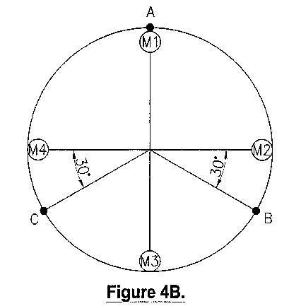
Figure 5 shows a graphical representation of force versus angular position of permanent magnet M1 of the system shown in Figure 4a;

Figure 6 shows a series of four graphs of input current versus angular movement of each permanent magnet of the system shown in Figure 4a;

Figure 7 shows a graphical representation of input voltage versus input current for each coil of the rotary device shown in the system of Figure 4a;

Figure 8 shows a schematic diagram of variation of natural magnetic attraction versus angular displacement of a rotor having a single permanent magnet and a stator having a single energizing coil, in accordance with a second embodiment of the present invention;
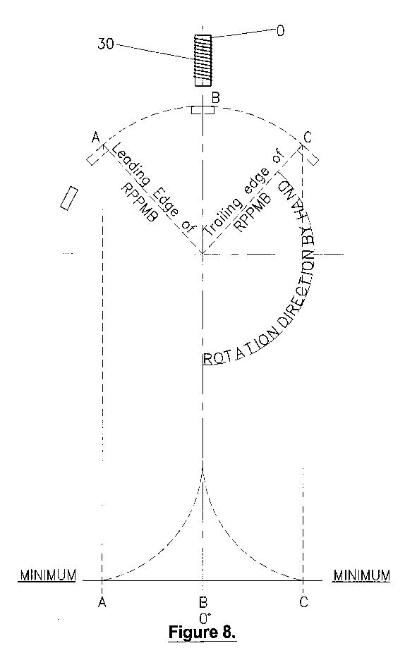
Figure 9 shows a graphical representation of magnetic field versus angular displacement in accordance with the second embodiment of the present invention;

Figure 10 shows a graphical representation of induced induction versus angular displacement of the permanent magnet in accordance with the second embodiment of the present invention; and

Figure 11 shows a further graphical representation of induced induction of electro-magnetic force versus angular displacement of the permanent magnet in accordance with the second embodiment of the present invention.

Detailed Description of the Drawings
As shown in Figure 4a according to the first embodiment of the invention a system is provided consisting of a rotor 11 having four permanent magnets M1, M2, M3, M4 which are evenly spaced at 90° with respect to each other.
The system includes a stator 12 consisting of three electro-magnet energizing coils A, B, C which are spaced 120° apart from each other.
Each coil A, B, C is connected in circuit with a power supply of 54 volts and a switch RS1, RS2, RS3.
Each of the contacts RS1, RS2, RS3 are part of a rotary switch 13 having contacts 14, 15, 16, 17 which are spaced at 90° with respect to an adjacent contact.
The rotary switch 13 is provided with contact brushes 18, 19 and is mounted on an axle 20 which is the same or common with the axle of the rotor 11.
Each of the contacts 14, 15, 16, 17 is specially configured with a trapezoidal shape, with the two non-parallel sides consisting of a straight side 21, and a tapered side 22 which tapers outwardly from top side 23 to bottom side 24.
The result is that each contact increases in width from the top side to the bottom side 24.
The brush 18 is able to be moved vertically relative to the contacts 14, 15, 16, 17 while the brush 19 is in constant contact with the base.
Although Figure 1 only shows the rotary switch 13 having a single series of four contacts 14, 15, 16, 17, for the three coil stator system, shown in Figure 4a there would in fact be preferably the contact discs on the axle 20.
Each contact disc would have contacts for a respective one of the coils A, B, C, but each brush for the other discs would be offset by 30° and 60° respectively.
A description of the operation of the system shown in Figures 1 to 4a will now be set forth below.
If it is assumed that the magnets M1, M2, M3, M4 are initially aligned as shown in Figure 4a with magnet M1 opposite one end of coil A, coil A is energized whenever one of the magnets M1 to M4 is aligned opposite it and for a predetermined time after the permanent magnet has passed it.
As shown in Figure 6 coil A is energized by contact RS1 providing an electrical connection through the rotary switch 13.
This occurs by one of the contacts 14 to 17 being aligned in contact with brush 18. At this time current is applied from the power source VA and continues to be applied until the brush 18 is no longer in contact with one of the contacts 14 to 17.
For the three coil/four pole arrangement of the first embodiment it is preferred that the brushes are moved to a vertical position where the width of each contact is sufficient for each of the switches RS1, RS2 and RS3 to be closed for 12°, 51', 50" of the rotation of the rotor 11. After this time the switches RS1 to RS3 are open and no more current is delivered to any one of the coils A to C. When the current to each of the coils is switched off a back EMF is induced in each of the coils A to C and this back EMF represented by item Z results in current being maintained in each of the coils for an additional small period of time after the contacts RS1 to RS3 are opened.
By switching the coils A to C in the above manner the rotor 11 can be induced to rotate with a lower amount of input current to the stator than would be required if current was delivered constantly to the coils A to C.
Table 1 below shows the resultant force on the rotor 13 for angular positions of the magnets M1 to M4 for angular displacements of magnet from 5° to 30°.
M1
5° CC 10°
CC 15°
CC 20°
CC 25°
CC 30° CC
M2
25° CW 20°
CW 15°
CW 10°
CW 5°
CW 0° CW
M3
55° CW 50°
CW 45°
CW 40°
CW 35°
CW 30° CW
M4
35° CC 40°
CC 45°
CC 50°
CC 55°
CC 60°
As shown when the magnets of the rotor 13 are rotated 5° at a time the resultant force on the rotor changes from a counterclockwise force from 5° to 15° to a clockwise force from 15° to 30°.
At 0°, 15° and 30° the resultant force on the rotor is 0 so that if the permanent magnets of the rotor were aligned in any of these orientation there would be no resultant force to urge the rotor either clockwise or anticlockwise.
As shown in Figure 5 a plot of magnitude of resultant force applied to the rotor against angular displacement of the rotor shows a sinusoidal curve having a cycle of 30°.
For a full 360° rotation of the rotor the rotor would experience 12 cycles of variation in resultant force.
What Table 1 and Figure 5 shows is that unless an additional force is applied to rotate the rotor clockwise or anticlockwise the rotor will not be able to spin continuously in either direction.
If it is assumed that it is desired to rotate the rotor clockwise, then the force must overcome the counterclockwise resultant force which occurs from 0° to 15°, 30° to 45°, 60° to 75°, etc., through the whole 360° rotation of the rotor.
Because each of the coils A to C has an iron core even when the coils are unenergized the natural magnetic attraction occurring between each magnet and the iron cores results in each magnet M1 to M4 attempting to move in a direction to the closest iron core.
Whenever a magnet is opposite an iron core the magnetic attraction is greatest and there is no force applied by that magnet to move the rotor either clockwise or counterclockwise. Likewise when a magnet is positioned midway between adjacent iron cores, there is also a resultant force of 0 which translates to no resultant force being applied to the rotor to rotate it in either direction by that magnet.
As shown in Figure 5 and Table 1, if magnet M1 is moved clockwise 5° there is a natural attraction between the magnet M1 and the iron core of coil A to pull the magnet M1 in a counter clockwise direction. If the resultant forces applied by the other magnets were sufficient to overcome the attraction between permanent magnet M1 and the iron core of coil A the rotor would still manage to move clockwise.
However as shown in Table 1 the angular position of the other magnets M2 to M4 results in an overall counterclockwise resultant force.
To overcome the resultant force it is necessary to produce a pole X at coil A of like polarity to magnet M1 and thus repel M1 away from coil A.
As shown in Figure 5 the strength of the magnetic repelling action between coil A and M1 must be sufficient to overcome the resultant force urging the rotor counterclockwise.
A current could be applied to the coil A for an angular displacement of 15° of magnet M1, but it is preferred that coil A be energized for only 12°, 51', 50" angular displacement of magnet M1. By applying current to coil A for this period of angular displacement a minimum amount of current is applied to coil A in order to overcome the resultant force counterclockwise which occurs for 0° to 15° of angular displacement of magnet M1.
Although current to coil A can be applied for longer than this period it has been discovered that by applying current for this period a back EMF is induced in coil A which adds to the repulsive force applied to magnet M1 by coil A.
Every time one of the magnets M1 to M4 is aligned at 0° with coil A, coil A is energized for 12°, 51', 50" of angular displacement of that magnet. Thus as shown in Figure 6 current ends up being applied to coil A at 0 degrees to 12°, 51 ', 50", 90° to 102°, 51', 50", 180° to 192°, 51', 50" and 270° to 282°, 51', 50".
A similar switching pattern is applied to coils B and C. For example, coil B is energized when magnet M2 has moved 30° to when it has moved 42°, 51', 50" and likewise coil C is energized when magnet M3 has moved 60° to 72°, 51', 50".
It is preferred that the rotor has a diameter of 230 mm and that each coil has a resistance of 6.8 ohms.
Figure 7 shows a graphical representation of input voltage versus input current for a coil resistance of 6.8 ohms and for a four pole rotor which is 230 mm in diameter.
The exact timing sequence for switching coils on and off will vary depending on the parameters of the rotary device and the controller.
Accordingly by varying the input voltage, coil resistance and overall impedance of the input circuit for each coil the duration during which a coil must be turned on will change.
In fact there are many factors which can change the timing sequence of switching on the coils, and some of these are summarized below.
The Stator
The variables include the choice of material used in constructing the stator iron core, the number of stator iron cores and their positioning as well as the physical size, section area and shape of the stator iron cores.
Rotor
The physical size and magnetic strength and shape of the polarized permanent magnetic body as contained in the rotor, the number of polarized permanent magnetized bodies being contained in the rotor, the positioning and spacing of the same, the use of all like polarities of permanent magnetic bodies or the use of alternating polarities for the permanent magnetic bodies.
Stator Coil
The physical size of the coils being positioned onto the stator iron core(s), the type of wire used to wind the coils(s) such as copper, silver, aluminum or others. The shape and section areas of the winding wire, such as round, square, triangular, rectangular and others; the number of turns and layers wound onto the coil and consequent ohms resistance; the method of winding onto a coil holder, single winding, double winding, double winding same direction, double winding opposite direction, left to right and vice versa, interwoven winding, whether the above examples would be wound onto a single coil holder.
Speed of Rotor
This can be controlled by the length of the directed (input) DC current (on and cut off period) and/or the control of the supply voltage used to supply the stator coils(s).
Other variations that may be made to the system include the following:
(a) The coils can be connected in series, parallel or series parallel.
(b) It is only when the north/south arrangements of the permanent magnets are used in the rotor that even numbers of permanent magnets are necessary, but not necessarily even numbers of pairs of stator coils positioned in the stator. Furthermore the direction DC current supplied to the stator coils in the north south arrangement above must be synchronized, meaning that the magnetic field as needed in the stator coil(s) must be of corresponding polarity to the stator coil(s), iron core end, which faces the permanent magnets.
(c) When using permanent magnets which are all of the same polarity, then any number of permanent magnets in the rotor may be used providing there is sufficient room to contain them, at even spacings on the rotor.
(d) The spacings between the permanent magnets must be exact; if too close to each other the directed DC current will become less effective; if too far apart the full potential will not be obtained.
(e) It is possible to have various combinations of permanent magnet and stator coil iron cores similar but not restricted to the following:
(i) Three magnets in the rotor, one to three stator coils can be used.
(ii) Five permanent magnets in the rotor, one to five stator coils can be used.
(iii) Nine permanent magnets in the rotor, one to three or nine stator coils can be used.
(iv) The output varies with each combination.
(v) Regardless of the rotor containing even or uneven numbers of permanent magnets the stator can operate with only one stator coil and stator iron core and still be highly effective but with reduced total output.
(f) The stator and rotor should be made from non-magnetic materials like wood, plastic, bronze and similar non-magnetic materials.
Although switching is performed in its preferred form by a mechanical rotary switch, it can also be performed by solid state electronics or other switching devices.
The length of the on period for each coil is the physical length ratio. When the brushes are in contact with the conductive part of the rotary switch and the non-conductive part.
This ratio is referred to as the frequency or number of ratios in one second.
The output produced by the rotary device can be mechanical and electrical at the same time or may be mainly electrical or mainly mechanical. The reason for this will be explained with reference to the second embodiment in which it is assumed the stator has a single energizing coil with an iron core and the rotor has a single permanent magnet.
When the rotor's permanent magnet is rotated very slowly by hand in the clockwise direction it is possible to determine the point where the natural magnetic attraction between the rotor's permanent magnet and the stator's iron core occurs.
When the leading edge of the permanent magnet has reached a point A as shown in Figure 8, the natural magnetic attraction begins and increases exponentially until the center of the permanent magnet is aligned at point B opposite the iron core 30.
If the permanent magnet is rotated away from point B the NMA will be at a maximum point B and then decrease from maximum exponentially until the trailing edge of the permanent magnet has reached point C and then ceases.
When the rotor is moved clockwise at a constant speed and an oscilloscope is connected to the stator coil it is possible to observe the movement of the permanent magnetic between point A and point B and then between point B and point C as shown in Figure 9.
An induced induction curve is then apparent on the oscilloscope and this induced induction produces a sine wave curve 31. Furthermore the induced induction between point A to point B is a negative going induced induction in this instance and the induced induction between point B and point C is a positive going induced induction in this instant.
It is also noted that the negative going and positive going induced induction curves are exactly the same but opposite to each other.
When the permanent magnet begins to induce a negative going induction in the stator coil at 0° of the sine wave curve 31, the induction induced is then at 0. At 90° of the sine wave curve the induced induction is at a maximum and then goes back to 0 when the permanent magnet is aligned with point B, or at 180° of the sine wave curve, when the permanent magnet starts to move away from its alignment with point B or is at 180° of the sine wave curve.
When the permanent magnet starts to move away from its alignment with point B and is moving towards point C the now positive going induced induction is first at 0 at 180° of the sine wave curve, then at a maximum of 270° of the reached point A as shown in Figure 8, the natural magnetic attraction begins and increases exponentially until the center of the permanent magnet is aligned at point B opposite the iron core 30.
If the permanent magnet is rotated away from point B the NMA will be at a maximum point at point B and then decrease from maximum exponentially until the trailing edge of the permanent magnet has reached point C and then ceases.
When the rotor is moved clockwise at a constant speed and an oscilloscope is connected to the stator coil it is possible to observe the moment of the permanent magnetic between point A and point B and then between point B and point C as shown in Figure 9.
An induced induction curve is then apparent on the oscilloscope and this induced induction produces a sine wave curve 31. Furthermore the induced induction between point A to point B is a negative going induced induction in this instance and the induced induction between point B and point C is a positive going induced induction in this instant.
It is also noted that the negative going and positive going induced induction curves are exactly the same but opposite to each other.
When the permanent magnet begins to induce a negative going induction in the stator coil at 0° of the sine wave curve 31, the induction induced is then at 0. At 90° of the sine wave the induced induction is at a maximum and then goes back to 0 when the permanent magnet is aligned with point B, or at 180° of the sine wave curve, when the permanent magnet starts to move away from its alignment with point B or is at 180° of the sine wave curve.
When the permanent magnets start to move away from its alignment with point B and is moving towards point C the now positive going induced induction is first at 0 at 180° of the sine wave curve, then at a maximum of 270° of the sine wave curve and then back to 0 at 360° of the sine wave curve.
It should be noted that 0° and 360° of the sine wave curve are not necessarily the same as point A for 0° and point C for 360° of the sine wave curve.
Points A and C are determined by the strength of the rotors permanent magnet and the section area and/or shape of the stator iron core.
The negative going induced induction between 0° and 180° of the sine wave curve produces an electro-magnetic force in the stator coil and iron core of opposite polarity.
The iron core end facing the rotor is of opposite polarity than the permanent magnet in this instance, as shown in Figure 10.
The positive going induced induction between 180° and 360° of the sine wave curve produces an electro-magnetic force in the stator coil and iron core of the same polarity in the iron core end facing the rotor, being of the same polarity as the permanent magnet in this instance.
When the permanent magnet reaches point A the natural magnetic attraction between the permanent magnet and the stator iron core is at its minimum and starts to move towards point B. When the induced induction then also starts to occur at 0° of the sine wave curve, being somewhere between point A and point B, the natural magnetic attraction has already increased.
When the permanent magnet is at 0° of the sine wave curve and is moving towards point B or 180° of the sine wave curve, the negative going induced induction in the stator coil is producing an electro-magnetic force (field) in the stator iron core with the iron core end facing the rotor being of an opposite polarity than the permanent magnet and is at zero effect at 0° of the sine wave curve, than at maximum effect at 90° of the sine wave curve and then back to zero effect at 180° of the sine wave curve.
The permanent magnet is then aligned at point B.
There the magnetic attraction force is proportional with the distance and this increases exponentially when moving from point A toward point B. There the iron core is fixed and stationary at point B. Accordingly it will be the permanent magnet that moves towards point B.
As an example, if the stator iron core was also a polarized permanent magnetic body of the same strength but of opposite polarity to the permanent magnet, the magnetic attraction force would be at least four times greater because of the distance factor as explained earlier.
Furthermore, this would also occur because of the doubling of the magnetic force between the magnetic north and south arrangement. It follows therefore that the magnetic attraction between the permanent magnet and the iron core and facing the rotor increases dramatically when the induced induction in the stator coil produces an electro-magnetic force of opposite polarity at the stator iron core end facing the rotor as described above.
The increase follows the sine wave curve starting from 0° to 90° of the sine wave and the above effect decreases from 90° back to 180° of the sine wave curve.
A combination curve of the natural magnetic attraction an the induced induction in the stator coil, producing an electro-magnetic force at the stator iron coil end facing the rotor of opposite polarity 33 is shown in Figure 10 from 0° to 180°. For 180° to 360° the stator iron coil and rotor of like polarities 34 are shown.
When the permanent magnet is aligned at point B and a direct current is supplied to the stator coil for only a short period starting at point B then the DC current is applied only long enough to overcome the natural magnetic attraction between the permanent magnet and the stator's iron core end facing the rotor. The directed DC current as supplied to the stator's coil is producing a like-polarity at the iron core end facing the rotor and thus is repelling the permanent magnet away from point B towards point C.
The natural magnetic attraction has thus changed to natural magnetic repulsion due to the like-polarity of the stator iron core end facing the rotor.
The length of the "on" period has to be sufficient to overcome the natural magnetic attraction and could be as long as until the trailing edge reaches point C where the natural magnetic attraction ceases. However there the positive going induced induction in the stator coil as produced by the permanent magnet produces an electro-magnetic force in the stator or iron core end facing the rotor, producing a like polarity as the permanent magnet starting at 180° of the sine wave curve or point B and zero at that instant. At 270° of the sine wave curve, it is at a maximum and then ends up at zero at 360° of the sine wave curve. In other words, at 270° of the sine wave the force is at maximum repulsion and there is induced induction in the stator coil depending on the speed of the rotor. The effect of variation on the speed of the rotor is shown by curves 35 in Figure 11.
As shown in Figure 11, regardless of the speed of the rotor the induced induction in the stator coil is at a maximum at 270° of the sine wave curve.
The on period can be brought back to the point where the induced induction is great enough to carry the electro-magnetic repulsion through to 360° of the sine wave curve and beyond point C. Therefore the greater the rotor speed the shorter the on period of the input DC current has to be due to the high induced induction in the stator coil as explained earlier. When the "on" period is switched off it is called the 'cut-off" point. From the cut-off point to 360° of the sine wave curve the repulsion is produced by back EMF, the induced induction in the stator coil as previously explained.
During the on period, the magnetic repulsion force produced between the stator iron core at point B and the permanent magnet can be viewed as a combined repulsion force. Some of this force is produced by natural magnetic repulsion of the permanent magnet and some by the input DC natural magnetic repulsion due to the like-polarity of the stator iron core end facing the rotor.
The length of the "on" natural magnetic repulsion due to the like-polarity of the stator iron core end facing the rotor.
The length of the "on" period has to be sufficient to overcome the natural magnetic attraction and could be as long as until the trailing edge reaches point C where the natural magnetic attraction ceases. However there the positive going induced induction in the stator coil as produced by the permanent magnet produces an electromagnetic force in the stator or iron core end facing the rotor, producing a like polarity as the permanent magnet starting at 180° of the sine wave curve or point B and zero at that instant. At 270° of the sine wave curve, it is at a maximum and then ends up at zero at 360° of the sine wave curve. In other words, at 270° of the sine wave curve, it is at a maximum and then ends up at zero at 360° of the sine wave curve. In other words, at 270° of the sine wave the force is at maximum repulsion and there is induced induction in the stator coil depending on the speed of the rotor. The effect of variation on the speed of the rotor is shown by curves 35 at Figure 11.
As shown in Figure 11, regardless of the speed of the rotor the induced induction in the stator coil is at a maximum at 270° of the sine wave curve.
The on period can be brought back to the point where the induced induction is great enough to carry the electro-magnetic repulsion through to 360° of the sine wave curve and beyond point C. therefore the greater the rotor speed the shorter the on period of the input DC current has to be due to the high induced induction in the stator coil as explained earlier. When the "on" period is switched off it is called the "cut-off" point. From the cut-off point to 360° of the sine wave curve the repulsion is produced by back EMF, the induced induction in the stator coil as previously explained.
During the on period, the magnetic repulsion force produced between the stator iron core at point B and the permanent magnet can be viewed as a combined repulsion force. Some of this force is produced by natural magnetic repulsion of the permanent magnet and some by the input DC current as supplied to the stator coil. Therefore if the induced magnetic force as produced by the input DC current in the stator coil is made equal to that of the permanent magnet with the same polarity, then half of this repulsion force between the on period and the cut-off point, in this instance, is from the natural magnetic repulsion of the permanent magnet as a reaction to the induced magnetic force as supplied by the input DC current to the stator coil. Therefore if the induced magnetic force as produced by the input DC current in the stator coil is made equal to that of the permanent magnet with the same polarity, then half of this repulsion force between the on period and the cut-off point, in this instance, is from the natural magnetic repulsion of the permanent magnet as a reaction to the induced magnetic force as supplied by the input DC current to the stator coil.
The input DC current as supplied to the stator coil produces the magnetic repulsion force and is the only outside input to the overall system for total movement between point A and point C
The total input can be summarized as:
(a) The combined natural magnetic attraction and the electro-magnetic force as produced by the induced induction in the stator coil between point A to point B.
(b) The combined magnetic repulsion force between the permanent magnet and the stator iron core facing the rotor during the on period and the cut-off point.
(c) The electro-magnetic repulsion (see induced induction as explained earlier) between the cut-off point and point C.
(d) The electro-magnetic repulsion produced by the back EMF as represented by shaded portion 36 of Figure 11.
According to another embodiment of the present invention the stator has two coils positioned at 180° with respect to each other and the rotor has three permanent magnets spaced at 120° apart.
As set out in Table 2 below from 0° to 30° the resultant force is 0 and from 30° to 90° the resultant force is clockwise. From 90° to 120° the resultant force is counter-clockwise. This completes a full cycle which is repeated three times throughout a 360° rotation of the rotor.
M1
5° CC
10° CC 15°
CC 20°
CC 25°
CC 30° CC
M2
55° CW 50°
CW 45°
CW 40°
CW 35°
CW 30° CW
M3
65° CC 70°
CC 75°
CC 80°
CC 85°
CC 90°
RF
CC
CC
CC
CC
CC
0°
With the above configuration of poles and coils if it is desired to move the rotor clockwise, current would need to be supplied to the coils of the stator to overcome the counter-clockwise force whenever this is counter-clockwise, but as explained previously, current does not need to be supplied to the coil to energize the coil for the full period during which the resultant force is counter-clockwise.
For convenience and ease of explanation the above embodiments have been restricted to permanent magnets on the rotor and coils on the stator. However the basic concept behind the invention does not change if the permanent magnets are replaced by coils which are energized to produce the appropriate magnetic poles.
Similarly for an AC rotary device a rotating magnetic field generated by the stator winding or by the rotor/armature winding could similarly be switched to reduce the amount of current required to maintain rotation of the motor in one direction and to maximize the influence of back EMF on maintaining rotation of the motor in a single direction.
The above principles also apply to generators where coils are energized to produce a magnetic field. In such a situation the coils are switched on for a time sufficient to maintain rotation in the single direction and to maximize the influence of back EMF which tends to maintain rotation of the rotor/armature in a single direction.
By using the above concept it is possible to produce an output which can be both mechanical and electrical at the same time. Current generated in the stator coil windings can be used as an output and likewise the torque generated by the rotor can be used to supply a mechanical output. Likewise only one or the other form of output may be utilized.
Alternative Energy Institute (July 17, 2002) ~ www.altenergy.org/news/newsletter79/copy79/copy79.html
Adams' Invention Poached Down Under
According to a recent article published by an Australian newspaper, two Australian inventors have developed the world's "first commercial machine which can power a house from a clean, green virtually free energy source." The story has been posted on the Aethmogen Technologies: New Energy Scientists website "for those interested in the subject of reverse engineering, plagiarism, and stolen intellectual and other property." In response to the anticipated production of the "Lutec 1000 Motor/Generator," noted Australian inventor Dr. Robert Adams reports background details to enforce his argument that this magnetic motor cannot be patented. Adam's writes, "This invention, which is mine, was granted a British Patent in 1996 along with Dr. Harold Aspden of the United Kingdom (IBM's Patent Director for 19 years), was placed in the public domain by international publication in Nexus Magazine and according to International Patent law, thenceforth becomes unpatentable!" Learn more about this unfolding drama from Down Under.
Engineers
Reporting Negative Results: Rosenthal and Cole ~ Ian
Bryce
Report by
Sterling D. Allan (March 8, 2003)
Engineers, Walt Rosenthal and Parke Cole were invited to measure the Lutec1000 in January 2001. Their measurements showed results showed 28% efficiency. The exchange was amendable, despite the negative test results. Rosenthal stated, "I walked them through the calculations carefully so they would understand, but they didn't want to believe the results." Test entailed a dynamometer measuring output the motor, powering with power supply from wall producing DC volts, optical shaft encoder on end of shaft to measure rpm. Results showed 50 Watts power going in and 14 Watts equivalent of mechanical power coming out.
After receiving the above synopsis, Walt Rosenthal added the following:
Report by Walt Rosenthal (March 8, 2003) ~
The inventors would start with fully charged batteries for the demonstration. They assumed that the battery terminal voltage would decrease linearly as the battery was used. So, after using the battery for, say, 30 minutes, they would again measure the battery terminal voltage, and subtract this value from the start voltage, then multiply that difference voltage times the known amp-hour capacity of the battery bank, to come up with their assumption of the total energy consumed from the battery bank. Unfortunately, battery terminal voltage is almost flat for perhaps 90 percent of the battery capacity, before it drops off rather steeply for the last 10 percent of it's capacity. Parke Cole and I tried to explain this to the inventors. I am not sure we succeeded. We were about the 15th group of people to show up on their door step after they went public. We were the first people to bring our own test equipment. The inventors said that the first people to show up were the Russian Mafia. Our bottom line was 50 watts of DC power input, which resulted in 14 watts of rotary mechanical power output. I hope the inventors have improved their device from where we tested it so that it now matches their statements of it's performance.
Follow-up Comment from Walt ~
From:
Walter Rosenthal ~ To:
sterlingda@greaterthings.com (March 15, 2003)
Subject:
Energy Wise 1000 mentioned at GreaterThings.com
Sterling: The pictures of the Lutec 1000 show that the inventors have added a second unit apparently driven by the motor and in line with the motor since Parke and I tested it... Walt
Feedback From Scott MacGregor ~
To:
Sterling D. Allan (March 09, 2003)
Subject:
Lutek 1000 only 28% efficient according to Rosenthal, 2001
independent measurement
Thanks for that update. It seems evident that although electro-magnets require energy input to "turn on", permanent magnets require energy input to "turn off"! The example given on their Website - the permanent magnet and electro-magnet supporting a weight from a steel beam - should demonstrate this principle. i.e., Energy must be inputted to the electro-magnet in order to overcome the weight. Although no external energy is required for the permanent magnet to support the weight, energy must be supplied to OVERCOME the magnet and cause the weight to fall...thereby producing useful energy. In other words, the permanent magnet is producing zero energy while supporting the weight.
Email from Patrick Bailey:
From:
Bailey, Patrick
February 20, 2008
RE: Zero Point Energy Machine from Australia - Lutec
...Walter Rosenthal traveled there with his high frequency digital oscilloscope and measured the devices.
IT IS THE SAME OLD LYING GAME!
People are measuring high freq. DC or fast pulsating AC with AC meters calibrated to sine wave 0.707 RMS.
You can not do that!
Using just AC meters (like an old VTVM), I could easily show you that a resistor, capacitor, and inductor arrangement will always give you over unity! (Just by ignoring the current to voltage phase angle.)
Walter measured the voltage vs. time digitally (storing many data points per cycle), and the current vs. time digitally, and then calculated the power point by point via computer, and then calculated the average power digitally - for input power and output power.
Then you can get the True output to input power ratio.
You
must use a high frequency oscilloscope with such computing
abilities!!!
...