Adam
CONTORET
Personal Propulsion System
Personal Propulsion System
Dreamscience Propulsion,
Thames Lubricants Estate,
Garner Street,
Stoke-on-Trent,
Staffordshire,
ST4 7DE
Telephone
+44 (0)1782 409682


http://www.gizmag.com/dreamscience-electric-thrusters/31315/
April 9, 2014
DreamScience
electric thrusters could give adrenaline sports a push
By C.C. Weiss
Motor power can make already crazy, awesome adrenaline sports even crazier and … awesomer. Just look at designs like the Gnarboard and Jetboard. Unfortunately, filling a garage with various forms of motorized gear could quickly bankrupt a professional sports star. If an experimental thrusting system from UK-based Dreamscience Propulsion makes it to market, it could save some of those dollars by rolling the fun of several types of motorized boards into one device. The electric propulsion system lends motor-muscle to skiing, surfing, paragliding and beyond.
Good things happen when Ph.Ds get into action sports. After trying his hand at paramotoring, one such Ph.D, Dreamscience's founder and director Adam Contoret, decided he didn't like the experience of strapping a big, coughing engine on his back, so he started to tinker around with his own thrust system.
"The thruster is a very powerful motor driving a fan, about 30,000 rpm," Contoret explains. "A modern jet engine has a turbojet propulser module at the core of the engine and this drives a large fan at the front of the engine that generates most of the thrust. Electric motor technology has recently progressed to the level where the turbojet core can be replaced with a high power electric motor. A turbojet core generates massive amounts of heat, so an advantage of a motor core is the cool exhaust air stream making extreme sports applications possible without the danger of getting burned."
Paragliding test
Dreamscience has gone through several different prototype designs using the thruster modules that Contoret describes. The latest prototype uses a foursome of 8-kW motor-powered thrusters to spin out 100+ lb (445+ N) of thrust. With the design still under development, Dreamscience hasn't put out a full spec sheet, but we do know that it uses a mix of carbon fiber fans and an aluminum frame, with a lithium-polymer battery pack powering the motors.
"Four [motors] draw about 700 amps at 55 volts on full tap," Contoret says. "That's a shed-load of power considering an average household draws 60 amps. The only way to get that kind of power is using the latest lithium polymer batteries, which have come on leaps and bounds in the past five years."
The Dreamscience thruster is envisioned as a sports power unit for surfing, skating, snow ...
While the original motivator was paragliding, Contoret quickly realized that the system could also be used for other sports, including skiing, land boarding and surfing. It straps into the same type of harness used for power kites in sport derivatives like kitesurfing. The rider holds onto the central bar, controls thrust with either a thumb throttle or bite control (the latter allows for better grip), and steers the direction of the thrust as needed with their arms.
"The thrusters pretty much swap in to wherever you would use a power kite," Contoret says.
Unlike those kites, the thruster system provides instant power, without the need to rely on factors like wind and weather. It currently offers a brief five minutes of run time, but Contoret and crew are working to increase that.
Contoret imagines that the thrusters will also find use in increasing jump height and pushing riders up hills. They can be spun around to reverse-thrust to a stop.
The Dreamscience thruster design is still in the experimental stages, and Contoret has been seeking out athletes more experienced than himself to test it with different sports gear. He explains that Dreamscience works in development, patenting and prototyping, so it will have to seek out a manufacturing partner if a thruster-bar is ever to make its way to production. He roughly estimates a retail price between US$5,000 and $10,000, with the possibility of dropping to a more mainstream price level later down the line.
Earlier this northern winter, professional snowboarder Jamie Barrow grabbed hold of the Dreamscience thruster prototype and fired his way across a frozen lake in St. Moritz, Switzerland, hitting speeds of 50 mph (80 km/h). You can watch him in the video below.
http://www.youtube.com/watch?v=zFHzWofHrwo
Paraglider
Thrusters
Version in video: Weight 8Kg all up with batteries, 5 minutes at full power, 25Kg Thrust (only enough thrust and climb for testing – we built this one to test for different modes of operation and fitment locations for paragliding and then for land board, snow board and ski as kite replacement)
Next version in engineering: Weight 10 to 12Kg all up with batteries, 15 minutes at full power and 40Kg Thrust. (60Kg burst thrust) (only need 25Kg thrust for level flight, so about 25 minutes burn time in level flight) (anticipated 1 to 2m/s, 200 to 400ft/min climb rate with wing such as Mojo 3 and 80Kg pilot).
Add : Coanda Effect Shrouds ... Barker Flow Straighteners ... Ford Air Straighteners &c...
APPARATUS
AND METHOD FOR PARAGLIDERS
US2013161451
US2013161451
Apparatus and method for propelling a user wearing paragliding equipment are disclosed The apparatus includes at least one thruster for providing thrust in a predetermined direction; and an attachment element for attaching the at least one thruster to a user's body such that the thruster is secured against the front portion of the user's body.
FIELD
[0002] The present invention relates to an apparatus and method for paragliders. In particular, but not exclusively, the present invention relates to an improved means of propulsion for use by an individual when engaging in paragliding, powered paragliding, paramotoring, hang gliding, and other similar sporting activities.
BACKGROUND
[0003] Paragliding equipment in general is well known and generally includes a harness section that a user secures to his body with loops and restraints to enable the user to be comfortably suspended in flight and move relatively freely, and a wing section (canopy) of fabric designed to act as an aerofoil for slowing the rate of fall of a user and for capturing lift from thermal air movement. In use, the user is suspended below the canopy via suspension wires.
[0004] Powered paragliding or paramotoring is also known, in which a paraglider mounts an engine or electric power source to his or her back to add power to the paragliding activity.
[0005] JP4092798 discloses such type of powered device.
SUMMARY
[0006] According to a first aspect of the present disclosure there is provided apparatus for propelling a user wearing paragliding equipment, comprising:
[0007] at least one thruster for providing thrust in a predetermined direction; and
[0008] an attachment element for attaching the at least one thruster to a user's body such that the thruster is secured against the front portion of the user's body.
[0009] According to a second aspect of the present disclosure there is provided a kit of parts comprising apparatus as defined in the first aspect of the disclosure and a harness element and a fabric wing member.
[0010] According to a third aspect of the present disclosure there is provided a method of propelling a user over land or water, comprising providing an apparatus as defined in the first aspect of the disclosure, providing a harness and a fabric wind member, and causing the at least one thruster to move air to thereby propel the user.
[0011] Aptly, the apparatus comprises two thrusters. This may help to balance the apparatus when attached to a user.
[0012] Aptly, the thrusters are provided at opposed ends of a rigid member, and the thrusters are attached to the user's body via the rigid member.
[0013] In some preferred embodiments the attachment element comprises a harness or belt.
[0014] Aptly, the attachment element further comprises a connector for connecting the harness or belt to the rigid member.
[0015] Aptly, the attachment element is arranged to provide attachment of the at least one thruster to the user's body in the region of the user's hips. With this arrangement, the user is allowed a high freedom of movement, including both a sitting position and a standing position.
[0016] Aptly, the at least one thruster comprises a housing and an air moving device mounted within the housing.
[0017] Aptly the apparatus further comprises a control device for adjusting the speed of the at least one thruster. This helps to enhance the user experience and may also act as a safety feature for giving increased controllability over the equipment.
[0018] In some preferred embodiments the control device is a hand-held unit. The user may be able to conveniently control wires of the paragliding unit as well as the speed of the thruster with a single hand.
[0019] Aptly, the control device comprises a user input means for the user to start, stop, increase and/or decrease the speed of the at least one thruster.
[0020] Aptly the apparatus further comprises a further control device for adjusting an angle of thrust provided by the at least one thruster. Again, this helps to enhance the user experience and controllability over the equipment.
[0021] Aptly, the further control device is a hand-held unit.
[0022] Aptly, the further control device comprises a further user input means for the user to change the angle of thrust of the at least one thruster.
[0023] Aptly the apparatus may further comprise at least one weighting element operably connected to the at least one thruster for influencing the direction of thrust provided by the at least one thruster.
BRIEF DESCRIPTION OF THE DRAWINGS
[0024] For a better understanding of the invention and to show how the same may be carried into effect, reference will be made, by way of example only, to the following drawings, in which:
[0025] FIG. 1 is a sketch showing schematically a front view of an apparatus according to one embodiment;
[0026] FIG. 2 is a sketch showing schematically a top plan view of an apparatus according to one embodiment;
[0027] FIG. 3 is an image showing a typical user wearing an exemplary apparatus;
[0028] FIG. 4 is a sketch showing schematically an exemplary apparatus;
[0029] FIG. 5 is an image showing the apparatus of FIG. 4 in more detail;
[0030] FIG. 6 is an image showing a typical user wearing an exemplary apparatus; and
[0031] FIG. 7 is an image showing a user wearing an exemplary apparatus along with a paragliding harness.


DETAILED DESCRIPTION
[0032] According to an embodiment of the present invention, as shown in FIGS. 1 and 2, apparatus 10 comprises a rigid member 12 which is typically a bar or tube made from a lightweight material. Suitably, the rigid member 12 is made from a lightweight metal or a suitably strong plastic or plastics composite material. In some preferred forms, the rigid member 12 is straight (i.e. rectilinear). However, in particular embodiments, the rigid member 12 may be curved, or include curves, for example to provide gripping portions which facilitate the holding of the rigid member 12 in a user's hands. Such gripping portions may, for example have a surface comprising a high friction material, for example a rubbery material, on which a user can maintain a strong and comfortable grip.
[0033] At respective opposed ends of the rigid member 12 is mounted a thruster 16. That is, each end of the rigid member 12 carries a thruster 16. Any suitable means known in the art may be used to attach the thrusters 16 to the respective ends of the rigid member 12, for example by means of mechanical fastening means, for example clips or bolts, or by suitably strong adhesive, or by welding. The thrusters 16 are operably connected to the rigid member 12 and may be fixedly attached to the rigid member 12 or moveably attached to the rigid member 12, for example. In other embodiments, the apparatus may include only one thrusters (e.g. mounted centrally to the user), or may include any other number of thrusters.
[0034] Each thruster 16 comprises a housing 18 which is attached to the respective end of the rigid member 12. The housing 18 defines a channel or passage 20 that defines an air flow pathway through the housing.
[0035] Associated with each passage 20 is an air moving means 22. Preferably the air moving means 22 comprises a fan or propeller 24 with a plurality of air-moving blades 24a. Preferably the air moving means is mounted with the passage 20. Air moving means 22 is configured to cause, in operation, a flow of air through the passage 20 from the front side F to the rear side R of the apparatus. The movement of air through the passage 20 by the air moving means 22 is sufficient to provide a forward thrust (that is, generally in the direction of arrow T) to the apparatus 10.
[0036] The housing 18 also provides protection against a rotor failure by the air moving means 22.
[0037] Air moving means 22 will, in preferred embodiments, cause movement of air through passage 22 by rotation of a fan or propeller about an axis A, extending perpendicular to the plane of the page in FIG. 1, that is, from the front to the back of the housing. The axis A will normally be arranged substantially centrally with respect to the passage 20.
[0038] A drive means or arrangement is provided to cause rotation of the fan or propeller about axis A. Preferred drive means is an electric motor. A single electric motor may be provided to drive the air moving means 22 of both thrusters 16, for example by way of drive belts or drive shaft. In this case, the motor may conveniently be mounted on the rigid member 12, approximately equidistantly from the respective thrusters 16. In preferred arrangements, however, each air moving means 22 has an associated electric motor which is preferably arranged co-axially with the air moving means (that is, co-axially with the fan or propeller 24, in preferred embodiments). In some preferred embodiments, the electric motor is coupled directly to the fan or propeller 24 without any intervening gearing or linkage.
[0039] The rotation of the fan or propeller about the axis A may be in the region of 10,000 to 100,000 rpm and more aptly between 25,000 and 45,000 rpm and even more aptly around 35,000 rpm. The thrust values may be around 30 to 50 pound of thrust (15 to 25 kg) per thruster 16. The thrust should be sufficient to propel the user, with net thrust possibly lower than the combined weight of the user and apparatus. In some situations it may be possible to increase the net thrust to a value greater than the combined weight of the user and apparatus.
[0040] The drive means requires a power source in order operably to cause movement of the air moving means 22. Where the drive means is an electric motor, the power source is conveniently a battery, or a battery pack. Other known portable sources of electric power are useable in principle, provided always that such sources can conveniently be carried by a user while engaging in paragliding or other such sport using the apparatus of the invention. A battery pack is illustrated schematically at 26 in FIGS. 1 and 2. As illustrated, the battery pack 26 is mounted on the outside of housing 18, but other locations may be possible, for example within the housing 18 (if the housing 18 is appropriately shaped) or within a hollow interior part of rigid member 12. The location of battery packs for the respective thrusters 16 (specifically for the drive means of the air moving means 22) is selected to ensure that the weight of the battery packs is evenly distributed with respect to the apparatus as a whole. It would be undesirable for one thruster 16 to appear to a user to be heavier than the other thruster 16.
[0041] In alternative arrangements, one or more battery packs 26 may be carried about the user's person, for example by means of a supporting harness, e.g. attachable around a user's neck as shown in FIG. 7, the battery pack 26 being connected to the electric motors by suitable electrical connectors, notably wires.
[0042] Typically, each of the thrusters may require in the region of 5 to 25 KW of energy, which may be delivered by a lithium polymer (LiPo) battery pack via an electronic speed controller to brushless motors with high magnetic fields. A fan with diameter of around 15 cm diameter turning at around 35,000 rpm using brushless motor and 14 cell LiPo battery of 5 AmpHour rating will produce about 12 kg of thrust. Current draw would be 150 Amps at 54 Volts (corresponding to about 8000 Watt power consumption).
[0043] The wind speed leaving the thruster 16 may be around 100 ms<-1 >or more, which is higher than conventional propellers (that turn at a few thousand rpm). As such, the torque on the thruster shaft is very low compared to a conventional propeller, resulting in a higher degree of manoeuvrability of the apparatus and more predictable control, avoiding torque steer. Also, the high wind velocity output of each thruster ensures that thrust is not significantly reduced by motion of the apparatus as the speed differential is not as significant. As such, even under extreme speeds including freefall the apparatus remains manoeuvrable.
[0044] Referring now in particular to FIGS. 3 to 6, a user 100 is shown wearing an attachment element 32, which in this case is a harness secured around the user's waist and legs (in a similar manner to a rock climbing harness), and which harness is attached to the thruster apparatus 10. Having the harness around the user's waist and legs, or in the region of the hips in general, helps to allow the user to adopt various positions (in the air and on the ground) including where the user is bent at the hips, without the apparatus being substantially affected by the movement or user's body shape. It will be appreciated that instead of a harness as shown in the figures, alternatively a line, cord, wire, cable, strap or belt could be used as the attachment element that fits around the user's waist. In some configurations the attachment element 32 may be sufficiently robust to assist in conveying thrust from the apparatus 10 to a user's body, so allowing greater precision by the user in setting the orientation, attitude or alignment of the apparatus 10.
[0045] The apparatus 10 also includes a connector 34 which in this case is a looped strap connecting the harness to the rigid member 12. In some embodiments the connector could include a quick release system acting to prevent separation of the user and the apparatus but allowing separation in an emergency situation. Such means are, per se, well known in the art. In some embodiments the connector may be integral with the attachment element.
[0046] In some preferred embodiments, the apparatus 10 includes a control device (not shown) for adjusting the speed (rpm) of the thrusters. This may be a hand held unit including a button or other user input means for allowing the user to specify the stopping and starting of the thrusters, and optionally also the increase or decrease in speed of the thrusters. The user input means may be mechanical or electronic, having a link, for example a wire, chord or wireless signal to the thrusters for signalling the speed change. When the control device is hand held, this helps the user to be able to keep his hands on the wires of the paragliding equipment to control the canopy, and at the same time control the thruster speed. Of course it is also possible to have the control device in other convenient areas for the user to reach.
[0047] In some preferred embodiments, the apparatus 10 includes another control device (not shown), in addition to or instead of the above-mentioned control device, for adjusting the angle of thrust of the thrusters relative to the user. This also may be a hand held unit including a button or other user input means for allowing the user to specify the direction of the thrusters. The user input means may be mechanical or electronic, having a link, for example a wire, chord or wireless signal to the thrusters for signalling the angle change. When the control device is hand held, this helps the user to be able to keep his hands on the wires of the paragliding equipment to control the canopy, and at the same time control the thruster angle of direction. Of course it is also possible to have the control device in other convenient areas for the user to reach, or the user could manually change the angle of the thrusters by adjusting the rigid member 12 for example.
[0048] For example, initially, for a standing start, the thrusters should face forwards for take off. Then subsequent to take off, and during flight mode, a user is likely to adopt a sitting position in the paragliding harness. This change of body position of the user is likely to alter the angle of thrust that the thrusters provide. Therefore, the above-mentioned control device (thruster adjuster) may be useful for the user to maintain the direction of thrust required.
[0049] In an alternative embodiment, any kind of weighting element could be operably connected to the thrusters so as to influence the direction of thrust by use of gravity. This could be a weighted chain for example hanging from the thruster housing 18.
[0050] A user 100 wearing the apparatus 10 of the invention, along with a paragliding harness 50 and wires 52 is shown in FIG. 7. In use the user can attach the apparatus 10 to his body and then don the paragliding equipment in the known manner.
[0051] With the present invention, the attachment of the apparatus to the front area of a user's body enables a standard paragliding harness to be fitted over the apparatus without special adaptation to either part. Also, the apparatus positioned on the body lies out of the field of use of the standard paragliding equipment, and thus does not interfere with the wearing of the paragliding equipment or the functioning of the paragliding equipment.
[0052] Furthermore, as a safety aspect, it will be appreciated that providing a connecting part between the thrusters and the attachment element that is also forward of the user's body will allow the user to more easily reach for a quick release button for example in an emergency situation, which would be more difficult to do if the thrusters were mounted on the user's back as per prior art devices.
[0053] It will be appreciated that with the present invention, superior control and handling of the apparatus can be achieved compared to prior known devices. Furthermore, although the apparatus of the present invention may require a higher fan speed than some known devices, the apparatus will be lighter and have a profile with a smaller surface area than known devices. Thus, less drag will be encountered in use.
[0054] In addition, since the apparatus allows for more acute handling, with the direction of thrust being completely controllable, this can have further benefits in terms of safety as well as user enjoyment. For example, avoidance of obstacles or hazards is more easily achievable.
[0055] Furthermore, by swivelling the rigid member by 180[deg.], for example, it is possible to reverse the direction of thrust and enable a controlled stop. In use in an airborne activity, it may be possible to use the apparatus to slow or arrest the decent of the user. Typically known parachutes, including backup parachutes, cannot operate in the height range of less than 100 m. The present invention could therefore be used as a short distance decelerator for reducing falling speed in an emergency situation.
[0056] Alternatively in other embodiments, the apparatus 10 may include a mechanism to prevent the thrusters from reaching an unwanted angle relative to the user. For example, a stopper element could be used to provide a maximum angle or a limited range of angles through which the thrusters can be rotated. This mechanism could be used to prevent, for example, reverse thrust when the thrusters are rotated through 180[deg.] for situations when this is not desirable. Optionally, the apparatus may also include a bypass mechanism to override the stopper element for use in emergency situations.
[0057] In certain embodiments, the apparatus 10 may include a quick release mechanism for use in emergency situations. For example, where the apparatus is tethered to the user's waist area, the quick release mechanism may include a means of lengthening the tether to a length such that the apparatus moves to around shoulder height of the user. Then, the user may hang onto the apparatus in a free fall deceleration manoeuvre. The user may use downward thrust to remain upright in a thrust decelerated fall.
[0058] It will also be appreciated that since the source of thrust is forward of the centre of mass of the moving body, this arrangement will be inherently more stable than having a thrust source behind the body. For example, in a crash situation, the human body is often thrown forward with a forward momentum. With known apparatus located behind the body, the apparatus could continue to push the body forward. With the present invention, the apparatus will thrust forward of the centre of mass and likely detach from the body. The invention could include a safety measure to ensure that the thrusters are automatically stopped upon detachment from a user.
PERSONAL
PROPULSION APPARATUS AND METHOD
WO2013093447
WO2013093447
A personal propulsion apparatus and method are disclosed. The apparatus (10) includes first and second air-moving thrusters (16) arranged at opposed ends a rigid member (12) and drive means operable to cause the thrusters to move
The present invention relates to a person propulsion apparatus and method. In particular, but not exclusively, the present invention relates to an apparatus and method for use principally in sporting or physical activities, in particular so-called "extreme sports" including skateboarding, snowboarding, skiing, surfing, power kiting and the like. The present invention provides an improved means of propulsion for use by an individual when engaging in such or similar activities.
BACKGROUND
Personal propulsion means for sporting and physical activities per se are known.
Examples include:
US 2007/0010143 and US 7 690 958 (Burgess) which teaches a large single propeller attached to a harness and mounted on a user's back;
US 7 179 141 (McMullen) which teaches a harness by which a user mounts an internal combustion engine on his back. The internal combustion engine has a belt-drive to an axle of a single propeller, which in turn is intended to impart motion to a user, e.g. when skiing;
US 5 222 569 (Martel) teaches a motor and propeller for mounting to a user's rear pelvic area for providing forward thrust, such as when skiing;
US 2006/0196991 (Martin) teaches a personal flight device which includes an engine and at least a pair of tiltable fans driven by the motor. The fans and motor are mounted on a housing which is secured to a pilot.
All of the above devices lack a high degree of flexibility and controllability for use in physical and sporting activities. The present invention seeks to obviate, or at least alleviate, disadvantages associated with prior art apparatus such as those identified above.
STATEMENTS OF INVENTION
According to a first aspect of the present invention there is provided personal propulsion apparatus comprising first and second air-moving thrusters arranged at opposed ends of a rigid member and drive means operable to cause the thrusters to move air. Aptly, each thruster comprises a housing mounted to a respective end of said rigid member, and an air moving device mounted within the housing.
Aptly, the drive means comprises an electric motor. In preferred embodiments each thruster has an associated electric motor.
In further preferred embodiments the personal propulsion apparatus further comprises an electric power source for the electric motor.
In preferred embodiments, in each housing is mounted the air moving device, and in or on each housing is mounted an electric motor operable to rotate the air moving device.
Aptly, the personal propulsion apparatus further comprises an electric power source for the electric motor mounted in or on the respective housings.
Aptly, the personal propulsion apparatus further comprises a belt or harness configured for mounting to a user's body and attachment means for attaching the rigid member and/or the respective thrusters to the belt or harness.
Aptly, the attachment means is a flexible attachment.
In some preferred variations the attachments means comprises a cord, cable, strap, wire, line or the like.
In further preferred embodiments the respective thrusters are spaced apart by a length not less than the span of a user's shoulders, and preferably by a length of about 60 to 120cm.
Aptly, the personal propulsion apparatus further comprises gripping means or a gripping surface arranged on the rigid member and configured to be held by a user's hands.
According to a second aspect of the present invention, there is provided a kit of parts comprising a personal propulsion device as defined in the first aspect of the invention and at least one member selected from the group comprising skis, a bicycle, tricycle or quadricycle, a skateboard, roller-skates, a surfboard, a snowboard, a land board, a water craft or a land yacht chassis.
According to a third aspect of the invention there is provided a method of propelling a user over land or water, the method comprising providing a personal propulsion apparatus as defined in the first aspect of the invention, providing carriage means selected from skis, ice skates, a bicycle, tricycle or quadricycle, a skateboard, roller-skates, roller-blades, a land board, a land yacht chassis, a snowboard, a water craft or the like, the user grasping and holding the rigid member in his hands, causing the thrusters to move air, thereby to propel the user, and adjusting the orientation of the personal propulsion device by moving the rigid member, thereby to adjust the direction of thrust, relative to the user, imparted by the thrusters.
BRIEF DESCRIPTION OF THE DRAWINGS
For a better understanding of the invention and to show how the same may be carried into effect, reference will be made, by way of example only, to the following drawings, in which:
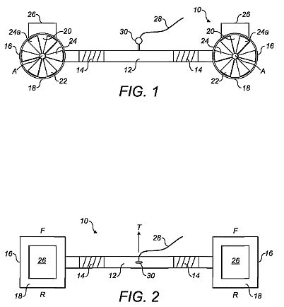
Figure 1 is a sketch showing schematically a front view of an apparatus according to the invention;
Figure 2 is a sketch showing schematically a top plan view of an apparatus according to the invention;
Figure 3 is an image showing a typical user holding an apparatus of the invention while standing on a land board;
Figures 4a to 4d are images of a typical user holding an apparatus of the invention in different orientations and positions.


DETAILED DESCRIPTION
Referring now to the drawings, the apparatus 10 of the invention comprises a rigid member 12 which is typically a bar or tube made from a lightweight material. Suitably, the rigid member 12 is made from a lightweight metal or a suitably strong plastic or plastics composite material. In some preferred forms, the rigid member 12 is straight (i.e. rectilinear). However, in particular embodiments, the rigid member 12 may be curved, or include curves, for example to provide gripping portions which facilitate the holding of the rigid member 12 in a user's hands. Gripping portions or regions are schematically illustrated at 14 in Figures 1 and 2. Such gripping portions 14 may, for example have a surface comprising a high friction material, for example a rubbery material, on which a user can maintain a strong and comfortable grip.
At respective opposed ends of the rigid member 12 is mounted a thruster 16. That is, each end of the rigid member 12 carries a thruster 16. Any suitable means known in the art may be used to attach the thrusters 16 to the respective ends of the rigid member 12, for example by means of mechanical fastening means, for example clips or bolts, or by suitably strong adhesive, or by welding. Each thruster 16 comprises a housing 18 which is attached to the respective end of the rigid member 12. The housing 18 defines a channel or passage 20 that defines an air flow pathway through the housing.
Associated with each passage 20 is an air moving means 22. Preferably the air moving means 22 comprises a fan or propeller 24 with a plurality of air-moving blades 24a.
Preferably the air moving means is mounted with the passage 20. Air moving means 22 is configured to cause, in operation, a flow of air through the passage 20 from the front side F to the rear side R of the apparatus. The movement of air through the passage 20 by the air moving means 22 is sufficient to provide a forward thrust (that is, generally in the direction of arrow T) to the apparatus 10.
The housing 18 also provides protection against a rotor failure by the air moving means 22.
Air moving means 22 will, in preferred embodiments, cause movement of air through passage 22 by rotation of a fan or propeller about an axis A, extending perpendicular to the plane of the page in Figure 1 , that is, from the front to the back of the housing. The axis A will normally be arranged substantially centrally with respect to the passage 20.
A drive means or arrangement is provided to cause rotation of the fan or propeller about axis A. Preferred drive means is an electric motor. A single electric motor may be provided to drive the air moving means 22 of both thrusters 16, for example by way of drive belts or drive shaft. In this case, the motor may conveniently be mounted on the rigid member 12, approximately equidistantly from the respective thrusters 16. In preferred arrangements, however, each air moving means 22 has an associated electric motor which is preferably arranged co-axially with the air moving means (that is, co-axially with the fan or propeller 24, in preferred embodiments). In some preferred embodiments, the electric motor is coupled directly to the fan or propeller 24 without any intervening gearing or linkage.
The rotation of the fan or propeller about the axis A may be in the region of 10,000 to 100,000 rpm and more aptly between 25,000 and 45,000rpm and even more aptly around 35,000 rpm. The thrust values may be around 30 to 50 pound of thrust (15 to 25 kg) per thruster 16. The thrust should be sufficient to propel the user, with net thrust possibly lower than the combined weight of the user and apparatus.
The drive means requires a power source in order operably to cause movement of the air moving means 22. Where the drive means is an electric motor, the power source is conveniently a battery, or a battery pack. Other known portable sources of electric power are useable in principle, provided always that such sources can conveniently be carried by a user while engaging in physical activity (e.g. sport) using the apparatus of the invention. A battery pack is illustrated schematically at 26 in Figures 1 and 2. As illustrated, the battery pack 26 is mounted on the outside of housing 18, but other locations may be possible, for example within the housing 18 (if the housing 18 is appropriately shaped) or within a hollow interior part of rigid member 12. The location of battery packs for the respective thrusters 16 (specifically for the drive means of the air moving means 22) is selected to ensure that the weight of the battery packs is evenly distributed with respect to the apparatus as a whole. It would be undesirable for one thruster 16 to appear to a user to be heavier than the other thruster 16.
In alternative arrangements, one or more battery packs 26 may be carried about the user's person, for example by means of a supporting harness, the battery pack 26 being connected to the electric motors by suitable electrical connectors, notably wires.
Typically, each of the thrusters may require in the region of 5 to 25 KW of energy, which may be delivered by a lithium polymer (LiPo) battery pack via an electronic speed controller to brushless motors with high magnetic fields. A fan with diameter of around 15 cm diameter turning at around 35,000 rpm using brushless motor and 14 cell LiPo battery of 5AmpHour rating will produce about 12 kg of thrust. Current draw would be 150 Amps at 54 Volts (corresponding to about 8000 Watt power consumption).
The wind speed leaving the thruster 16 may be around 100 ms<"1> or more, which is higher than conventional propellers (that turn at a few thousand rpm). As such, the torque on the thruster shaft is very low compared to a conventional propeller, resulting in a higher degree of manoeuvrability of the apparatus and more predictable control, avoiding torque steer. Also, the high wind velocity output of each thruster ensures that thrust is not significantly reduced by motion of the apparatus as the speed differential is not as significant. As such, even under extreme speeds including freefall the apparatus remains manoeuvrable.
In some embodiments, fastening means 28 may be provided for attaching the apparatus 10 to a user's body, for example to a harness or belt. For example, the fastening means may attach the apparatus 10 to the user's body such that the apparatus is held forward of the user's body. In this case the apparatus would act to pull the user along rather than push the user. The fastening means may typically be in the form of a line, cord, wire, cable, strap or belt. In some configurations the fastening means 28 may be sufficiently robust to assist in conveying thrust from the apparatus 10 to a user's body. This may have the advantage of reducing the strain on a user's arms as he holds the apparatus 10 in use, so allowing greater precision by the user in setting the orientation, attitude or alignment of the apparatus 10. In other embodiments, the fastening means 28 is intended only to prevent separation of the apparatus 10 from the user in the event that the user lets go of the rigid member 12, for example as a result of an inadvertent trip or fall. In some embodiments, the fastening means maybe provided with user-operated quick release means, shown schematically at 30 in Figures 1 and 2. Such means are, per se, well known in the art. In some embodiments, the fastening means may attach the apparatus to the user such that the thrust force acts through the user's centre of mass. This may be useful when it is preferred the apparatus propels the user from their centre of mass, rather than producing an adverse moment that may affect the user's balance or direction.
Referring now in particular to Figure 3, a user 100 is shown grasping an apparatus 10 of the invention. The user 100 is standing on a land board 200. A land board 200 is broadly similar to a conventional skateboard but is generally larger and has four wheels mounted externally of the board perimeter (in contrast to a skateboard where the wheels are typically arranged underneath the board). Land boards are known for use in the sport of kite land boarding where the user is pulled along overland (beach, hard surface, grass etc) by a kite. The land board 200 is just one example of a suitable vehicle or conveyance for use with the apparatus of the invention, other examples including skateboards, bicycles, tricycles, quadricycles, roller-blades, roller-skates, skis and snowboards. The apparatus 10 may be used in water sports in conjunction with water craft (small boats, dinghies, canoes and kayaks), surfboards and the like. In other possibilities, the apparatus 10 can be used in conjunction with the chassis of a land yacht (that is, a land yacht without its mast and sail) or similarly constructed vehicles.
As can be seen from Figure 3, in use, the user 100 grasps the apparatus 10 so that a firm hold is obtained on the rigid member 12. The user 100 holds the apparatus 10 generally forwardly of his body with the thrusters 16 in operation. A "jet" of air is provided from each thruster 16, in a rearward direction, so urging the apparatus 10 to move forwardly. As the user 100 is mounted on land board 200, the thrust imparted by the thrusters 16 causes the land board 200 to move forward, carrying the user in a forward direction.
Figures 4a to 4d illustrate some of the various different attitudes and orientations which a user 100 may cause the apparatus 10 to adopt, in order to control his motion. As will be clearly apparent, the user 100 can position the apparatus 20 by movement of his wrists, elbows and shoulders so that an almost infinite number of positions of the apparatus 10 can be adopted. Arrows D<1> to D<4> illustrate possible rotations of the apparatus 10 (by movement of the user's wrists) to vary the orientation of the apparatus 10. A user 100 soon becomes adept at setting the position, orientation and/or attitude of the apparatus 10 to match his desired speed and direction of motion. In a particular example, deceleration can be achieved by rotation of the apparatus so that the propulsion force is directed rearwardly. In further embodiments, a user operable control device may be provided by means of which the user 100 can control the operation of the thrusters 16. In particular, the user may control the amount of thrust provided by controlling the speed of movement of the air moving means 22. In further embodiments, the control device is operable to control the respective thrusters 16 independently, for example to compensate for environmental conditions (wind, terrain) or for changes of direction.
A user operable control device may comprise a mouth-operated controller to stop, start, increase speed, decrease speed, etc. of the thrusters. This would enable the user to keep both hands free to grip the rigid member.
It will be appreciated that in general the apparatus of the invention may be used to assist a user in sporting activities to increase their velocity and momentum compared to the usual velocities and momentums achieved without such apparatus.
It will be appreciated that with the present invention, superior control and handling of the apparatus can be achieved compared to prior known devices. Furthermore, although the apparatus of the present invention may require a higher fan speed than some known devices, the apparatus will be lighter and have a profile with a smaller surface area than known devices. Thus, less drag will be encountered in use.
In addition, since the apparatus allows for more acute handling, with the direction of thrust being completely controllable, this can have further benefits in terms of safety as well as user enjoyment. For example, avoidance of obstacles or hazards is more easily achievable.
Furthermore, by swivelling the rigid member by 180[deg.], for example, it is possible to reverse the direction of thrust and enable a controlled stop. In use in an airborne activity, it may be possible to use the apparatus to slow or arrest the decent of the user. Typically known parachutes cannot operate in the height range of less than 100 m.
It will also be appreciated that since the source of thrust is forward of the centre of mass of the moving body, this arrangement will be inherently more stable than having a thrust source behind the body. For example, in a crash situation, the human body is often thrown forward with a forward momentum. With known apparatus located behind the body, the apparatus could continue to push the body forward. With the present invention, the apparatus will thrust forward of the centre of mass and likely detach from the body. The invention could include a safety measure to ensure that the thrusters are automatically stopped upon detachment from a user.
With the present invention, the attachment of the apparatus to the front area of a user's body enables standard sporting equipment, for example a paragliding harness or power kite harness, to be fitted over the apparatus without special adaptation to either part. Also, the apparatus's position of use with respect to the body lies out of the field of use of most sporting equipment, and thus does not interfere with the wearing or the functioning of the sporting equipment.
Furthermore, as a safety aspect, it will be appreciated that providing a connecting part between the thrusters and the body that is also forward of the user's body will allow the user to more easily reach for a quick release button for example in an emergency situation, which would be more difficult to do if the thrusters were mounted on the user's back as per prior art devices.