Harold
CROZIER
Water Carburetor
Water Carburetor
https://www.youtube.com/watch?v=BR9CeCiVrHw
Shell
Oil Scientist Admits 1,000 mpg Barrier Broken in 70s!
Mentions Crozier :
http://www.gasholemovie.com/
Gashole
“Actor Scott D. Roberts and his filmmaking partner, Jeremy Wagener are the unlikely men behind the new documentary GasHole. Narrated by The O.C. and American Beauty actor Peter Gallagher, the film chronicles the history of oil prices and alternative fuels. It will screen for one night only at 7 p.m. Tuesday at the Village 8 Theater in Louisville.
This is its second stop in Louisville; a screening on July 14 sold out. The idea started 21/2 years ago when gas prices were at a then-high of $2.20 and a letter to the editor in The Modesto Bee newspaper sparked Roberts’ interest. The letter writer told of a Buick Roadmaster he saw come to the Crows Landing Naval Airfield in the 1940s that its inventor claimed was water-injected and could get 100 miles per gallon.
The inventor said he became a millionaire by selling the patent to Shell Oil Co., but one of the conditions was he could not make any more. “His story was jaw-dropping,” Roberts said. So Roberts called his friend Wagener, an L.A.-based writer-director, and said he might have a great idea for a movie.
The two began researching it and tracked down Kunde, who tells his story in the film. From there, the filmmakers went in search of the elusive patent sold to Shell. They found one from 1946 registered to a man who lived 20 miles outside Modesto; they thought it could be the invention in question. They brought the design to an engineer, who agreed that it might be able to improve fuel economy. From there, the documentary took off.
Kunde’s story led them to find other documented cases of fuel-saving inventions that never have seen the light of day. They include Texas inventor Tom Ogle’s 100-mpg vapor fuel system and Shell’s own internal 1977 publication “Fuel Economy of the Gasoline Engine,” which shows that Shell engineers were able to achieve 149.95 mpg on a 1947 Studebaker. www.gasholemovie.com
http://www.hulu.com/watch/231050
Gashole
Movie
Water
carburetor
US2458256
Jan. 4, 1949. US2458256
Description
Our invention relates to a water carburetor and has for its principal object, to provide simple, inexpensive and highly efficient means, whereby a regulated and controlled amount of water is inducted into air horn of a gasoline carburetor to mix with the air stream passing to said carburetor and from the latter, into the combustion chambers of an internal combustion engine. Particularly the invention relates to an improved device for introducing water into the carburetor intake air stream at rates in accordance with the quantities or rates of the air flow, for the several purposes of increasing the volumetric efliciency of the engine; suppressing detonation, decreasing fuel consumption, and increasing the power output and general performance efficiency of the engine.
Our major object is to accomplish these purposes by a novel assembly comprising a tubular or ring-like member insertible between the carburetor and air filter and containing a water induction nozzle of Venturi characteristics, and a directly connected body containing a float controlled water supply chamber from which water is delivered to the nozzle in accordance with the rate of air flow to the carburetor.
Particularly contemplated is the provision of means whereby air is mixed with water passing to the nozzle, and specifically in a manner whereby the induction of air by the nozzle-created suction elevates the water from a normal level below the nozzle position. i
A further object of our invention is, to provide a simple, practical and highly efficient high speed bleeder, which acts positively and automatically to produce a water-air mixture which, when combined with the main fuel and air mixture forms an ideal fuel for internal combustion engines.
Our present application is an improvement on our copending application on Anti-knock or detonation dampening device, filed March 20, 1944,-Ser. No. 527,252, now Patent No. 2,407,478.
With the foregoing and other objects in view, our invention consists in certain novel features of construction and arrangement of parts which will be hereinafter more fully described and claimed and illustrated in the accompanying drawings, in which:
Fig. 1 is a plan view of our improved water carburetor.
Fig. 2 is a vertical section taken on the line 2-2 of Fig. 1 and showing parts of the air cleaner and carburetor with which our device is combined.
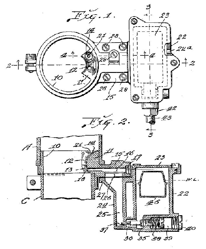

Referring by numerals to the accompanying drawings which illustrate a preferred embodiment of our invention, Hi designates a ring having a lower portion suitably clamped on the inlet end of a conventional carburetor horn C and with its upper portion disposed within the lower end portion of the air cleaner outlet A.
Formed integral with the upper portion of ring ill, on the inner face thereof is a lug or internal projection ll, arcuate in length to conform to the wall of said ring and which lug functions as a nozzle for the induction of water into the carburetor air intake stream and in accordance with its rate of flow.
From the upper rear edge of this lug, its upper or exposed face curves inwardly toward the center of the ring and downwardly to a horizontal plane a short distance above the bottom of said lug, thus forming a short vertically disposed duct or channel l2 that is arcuate in horizontal section and convex in vertical section to present an air-contacted surface having in cross-section as viewed in Fig. 2, a Venturi section shape.
From the horizontally disposed lower edge of this duct, the front face of the lug is undercut to form a horizontally arcuate vertically inclined face I3.
Formed in one end of the curved face l2 of nozzle l I, at the top thereof, is a shallow depression H.
Formed integral with ring I0 directly opposite the nozzle II is an external projection or lug 15, in which is formed a centrally disposed horizontal duct l6 closed at its outer end by a plug l1 and its inner end, which is slightly smaller than its outer portion, terminates in a jet aperture. It on the lower portion of undercut face 13 just below the lower end of the channel I 2.
Formed in lug l5, parallel with duct I6 is a duct 15, the rear end of which is closed by a plug 20 and the forward portion of this duct extends upwardly in nozzle H and terminates in an air inlet aperture 2| in the center of the depression H.
A substantially rectangular housing 22 having a removable cover 23, provides a water supply chamber and integral with one side of said housing is a vertically disposed housing 24 having a water well 25, the upper end thereof communicating through an aperture 28, with the rear portion of duct to.
Formed in the upper portion of one of side walls of housing 22 is a breather aperture 22a. Formed integral with the upper end of housing 24 is a flange 21, upon which-rests lug i5, and the parts being secured to each other by screws or bolts 28.
Screw seated in lug i along side duct I6, is a screw plug as having a diametrically disposed aperture 29a, that registers with duct i9, and depending from said screw plug is a small tube 3| that depends into well 25 and its lower end being closed by a plug 22.
The upper end portion of tube 3| fits snugly in an aperture 38 formed in lug I5 below plug 29 and formed through the wall of said tube throughout its length are several small air Jet apertures 34.
The upper one of these apertures is disposed below the normal water level prevailing in the chamber within housing 22, which water level is indicated by dotted line WL in Figs. 2, 3 and 4 and ring it and housing 22 are relatively disv a, 7 in the airhorn of the gasoline carburetor above the butterfly thereof.
Under normal conditions with float elevated, finger 48 bears against the outer end of plunger 44 and holds needle 45 against its seat 42 and when water is withdrawn from the float chamber, and the float lowers, the pressure of finger 48 against plunger 44 is relieved and hook 44a in groove 49 acts on plunger to withdraw the needle valve 45 from its seat, thus permitting water to enter the float chamber from duct 43.
Screw 35 is adjusted so as to control and regulate a metered flow of water from the float chamber into wall 25. Suction produced as a result of acceleration of motor speeds and increased rates of air flow along the nozzle surfaces l2 and I3 draws water through duct l6 from the top of well 25, which water discharges from the jet aperture to be picked up and mixed with the air posed so that ducts l6 and 19 are above said normal water level. Perforated tube 31 in operation, provides a high speed bleeder for automatically delivering water spray to the air stream as it passes from the air filter to the carburetor.
Means for controlling a metered flow of water from the chamber within housing 22 into the lower portion of well 25, comprises a screw 35 seated in the lower portion of housing 22 and provided with a tapered end portion 36, which enters a port 31, communicating with the lower end of well and arranged between the head of said screw and the wall in which the screw is seated is an expansive coil spring 38.
The outer end of the chamber 39 occupied by screw as, is closed by a screw plug 40, thus preventing leakage of any water that might seep from the chamber in housing 22, past the threaded portion of said screw.
Located in one end of housing'22 is a tubular fitting 4! having a seat 42 for a needle valve and connected to the outer end of said fitting is a water supply duct 43 which may lead from the radiator hose or from a small tank conveniently located beneath the engine hood. I
Arranged for sliding movement in fitting 4|, is a plunger 44, non-circular in cross section, and the outer end of said plunger terminates in a needle valve 45, which cooperates with seat 42 in controlling the flow of water from duct 43 into the chamber within housing 22.
A conventional float 46 is pivoted at 41 beneath fitting 4i, and extending upward from said pivot is a narrow finger 48 that bears against the outer end of plunger 44 and the upper end of this finger is bent downward to form a hook 48:; that engages in a groove 49 formed in the rear portion of plunger 44 (see Fig. 3-).
Projecting upward from the bottom of housing 22, is a web 50, which serves as a stop to limit the downward movement of float 46.
When the motor, with which our water carburetor is associated, is at idle speed no water is taken into the air stream and likewise while going down grades in gear, no water is taken in.
The device injects water only when the motor picks up the load under partial and full throttle, a Vacuum tending within said passage from one side only passing to the gasoline carburetor.
With particular reference to the displacement of water from the well 25 into passage i8, it will be noted, see Fig. 5, that the normal water level in the well and tube 3| is above the uppermost aperture 34, and consequently that no air flow through the aperture into the well occurs until the suction communicated from passage l8 lowers the water in the tube to the aperture depth. Thereupon the air stream entering the well beneath the water level agitates and entrains the water to a degree causing it to be carried by the air stream into passage It for admixture with the air taken into the carburetor.- And of course, lowering pressures communicated from passage I6 produces increasing air flow into the well and increasing displacement of water therefrom. As water is so displaced from the well and the water level therein drops, openings 34 progressively admit air into the well, but individually with decreasing air passage since each upper opening 34 uncovered by a drop of the outside water level acts as an air bleeder with relation to the apertures below.
Thus the air taken into the gasoline carburetor is heavily laden with moisture and the resultant vaporized mixture of air, water and gasoline provides an ideal gaseous fuel for the development of increased power, cooler engine temperatures, elimination of preignition and detonation, also, the superheated steam action in the dissolving of the carbon holding gums resulting from use of hydrocarbon fuels in engines.
Among the particularly novel and advantageous features of our invention are, the nozzle II and the high speed bleeder 3|, which are arranged and constructed so as to act automatically in response to engine speeds and loads to provide an air water mixture and deliver same directly into the air stream from the air filter to the gasoline carburetor.
REFERENCES CITED The following references are of record in the flle of this patent:
UNITED STATES PATENTS
Cited Patent Filing date Publication date Applicant Title
US1727197 * 25 Nov 1925 3 Sep 1929 Ensign Carburetor Company Internal-combustion engine
US1972686 * 26 Aug 1931 4 Sep 1934 Lorenzen Christian Carburetor
US2040020 * 19 Jul 1934 5 May 1936 William B Parker Carburetor
US2108556 * 31 Aug 1937 15 Feb 1938 William G Hardt Air humidifier for a combustion engine
US2441301 * 19 Mar 1945 11 May 1948 Thompson Prod Inc Apparatus for introduction of antiknock fuel mixture
GB384689A * Title not available
GB465474A * Title not available
* Cited by examiner
Referenced by
Citing Patent Filing date Publication date Applicant Title
US2603466 * 27 Oct 1948 15 Jul 1952 Thompson Prod Inc Mounting for supplementary feed device for internal-combustion engines
US2611594 * 27 Oct 1948 23 Sep 1952 Thompson Prod Inc Supplementary fluid feed device with automatic tandem metering valves
US2699326 * 31 May 1951 11 Jan 1955 Thompson Prod Inc Collar mounted dual actuated fuel feed device
US2710176 * 3 Dec 1951 7 Jun 1955 Caddock Richard E Liquid metering device for internal combustion engines
US2717149 * 9 Oct 1951 6 Sep 1955 Thompson Prod Inc Fluid feed device
US3208738 * 20 Sep 1961 28 Sep 1965 Acf Ind Inc Carburetor
US7510130 * 5 Dec 2002 31 Mar 2009 Fuji Bc Engineering Co., Ltd. Fluid device having an orifice aperture and method of changing the aperture size of such an orifice aperture
Antiknock
or detonation dampening device
US 2407478
DescriptionUS 2407478
Our invention relates generally to internal combustion engines and more particularly to simple and efficient means for counteracting and dampening detonation or engine knock and the principal object of our invention is to provide simple and efficient automatic means for introducing steam vapor to the carburetor to mix with the combustible gaseous mixture drawn into the cylinders.
The steam vapor when entering the combustion chamber acts as a coolant during the explosion cycle and its expansion through the differential in temperature will act as a cushion or dampener respectively producing a gas of its own to further assist combustion, so that detonation, more familiarly known as an engine knock is thus eliminated.
It may readily be seen that with a device of this kind, higher compression ratios can be utilized materializing more power and fuel economy and lower grade fuels.
Further objects of our invention are, to provide a device of the character referred to, having a simple and effective steam generator, constructed so as to` be conveniently mounted on the exhaust manifold of the engine and thus be heated by the exhaust gases passing through said manifold and further, to provide means for utilizing the velocity of the air entering the carburetor for regulating the amount of steam to correct proportions for all engine speeds and throttle positions.
With the foregoing and other objects in view, our invention consists in certain novel features of construction and arrangement of parts which will be hereinafter more fully described and claimed and illustrated in the accompanying drawing in which:
Fig. 1 is an elevation view partly in section and showing the device associated with the air filter, carburetor and exhaust manifold of an internal combustion engine.
Fig'. 2 is an enlarged horizontal section taken on the line 2-2 of Fig. 1.
Fig. 3 is a vertical section taken through the center of the steam generator.
Fig. 4 is a horizontal section taken on the line 4-4 of Fig. 3.
Fig. 5 is a detail section of a oat actuated valve for controlling the flow of water to the steam generator.

Connecting the carburetor with the air filter is a collar I4 in the center of which is a short vertically disposed tube I5 having a Venturi passageway I6, said tube being connected to the wall of collar by a narrow web I1 through which is formed a duct I8 the inner end of which communicates with the center of the Venturi I6.
The steam generator includes a metal disc I9 plate 2I. Bolts or the manifold, thereby securing the generator thereto.
Thus with the cover secured on the disc, the duct 20 provides an elongated steam generating chamber.
Secured to cover plate 2I and leading from the inner end of duct 20 to the cuter end of duct I8 is a conduit 22. As a result of this arrangement the steam or moist vapor from the generator enters the carburetor at a point in advance of its main nozzle. A small tank. or container 23 is located below the source of water supply I3, and located in the bottom of said tank is a valve housing 24 provided in its upper end with an inlet 25 which is normally closed by a downwardly opening check valve 26. A stem 21 connects valve 26 to a float 28 within tank 23.
Leading from the source of water supply I3 to the lower portion of valve housing 24 is a conduit 29 in which is located a valve 30.
Leading from the lower portion of tank 23 to the outer end of duct 20 in the steam generator is a conduit 3|, the flow of water through which is controlled by a valve 32 actuated by a conventional thermostat 33 located on exhaust manifold I2 adjacent the steam generator.
Through the action of oat actuated valve 26, a constant supply of water is maintained in reand under a predetermined degree of heat from the exhaust products of combustion passing through manifold I2, thermostat 33 will open valve 32, thereby permitting water to flow through conduit 3I into duct 20 in disc I9, which latter is also heated by the products of combustion passing through the exhaust manifold. Thus, the Water owing through the elongated duct in the disc I9 will be heated and nally converted into steam which is drawn through conduit 22, and thence through duct I8 to unite and mix with the air drawn through the venturi and such air enters the carburetor to unite with the liquid hydrocarbon to form an exceptionally effective and powerful gaseous fuel for the engine.
The addition of moisture in vapor form, to the gaseous fuel drawn into the combustion chambers of the engine, materially increases the power output counteracts the formation of carbon in the combustion chambers and assures smooth running of said engine- The steam generator comprising disc I9 and cover 20 is directly attached to the exhaust manifold and has a relatively large heating area with a small water space thus insuring the rapid and effective generation of steam while the device is in operation.
Float actuated valve insures a constant supply of water in receptacle 23, valve 32 regulates the flow of generator and passageway I6 regulates the amount of steam to correct proportions in relation to engine speeds and throttle position.
Thus it will be seen that we have provided an anti-knock or detonation dampening device which is simple in structure, inexpensive of manufacture, exceptionally economical in point of fuel consumption, capable of being readily used in connection with practically all internal combustion engines, and said device being very effective in performing the function for which it is intended.
It will be understood that minor changes in the size, form and construction of the various parts of our anti-knock or detonation dampening device may be made and substituted for those while thermostatic water to the steam duct.
Referenced by
Citing Patent Filing date Publication date Applicant Title
US3975466 * 10 Apr 1975 17 Aug 1976 Peter Lilicy Carburetor auxiliary fluid injector
US4366104 * 25 Jan 1982 28 Dec 1982 Miller Harvey R Fuel feed system for internal combustion engines
US4393817 * 25 Sep 1980 19 Jul 1983 Owen, Wickersham & Erickson Combustion and pollution control system