Willard CUSTER
Channel Wing

"It's the speed of the air, not the airspeed."
2. Custer Channelwing: The Facts -- Too Good to be True ?
3. Custer Channelwing: Dreams and Schemes -- Developing a Great Idea.
4. The Custer Channel Wing - P-20
5. Raul Colon : Willard Custer Ideas, Ready for the Aviation World?
6. Williard Custer : Theory of Channel Wing Aircraft
7. Popular Mechanics ( May 1947 ) : The Wing that Fooled the Experts
8. Air Progress Magazine ( October/November, 1964 ) ; Custer's Production Model Takes Bow
http://www.custerchannelwing.com/02_history.html
Custer Channelwing: Intro
"It's the speed of the air, not the airspeed."
CCW-5 five
seconds into takeoff run.
This aircraft can be seen at the Mid Atlantic Air Museum, in
Reading, Pennsylvania.
The idea of the channelwing pre-dates most of those who are reading this site. It all began in the 1920s, when Willard Custer took shelter in a barn during a near hurricane velocity storm. Much to his surprise and fascination, the roof of the barn suddenly lifted off, and soared through the air. He wondered why an airplane had to gather speed on a runway, while a barn roof, a poor airfoil by any reckoning, could fly from a standing start. He soon came to the realization that it was the speed of the air over the surface, not the speed of the surface through the air, that created lift. Bernoulli principle in both cases, but an application that had eluded aviation up to that time. He settled on the idea of pulling the air through channels that were, in fact, the lower half of a venturi. He was reversing the normal method of powered flight. Instead of using the engines to move the airfoil through the air, he used the engine to move the air through the airfoil. His channel had the effect of going several hundred miles per hour, due to the induced air flow,while standing still. The airflow over the surface of the channel created conventional lift, and a lot of it. It was at this point that Custer settled on," It's the speed of the air, not the airspeed", which became his mantra of, "aerophysics".
CCW-1 hanging
in the Smithsonian Garber facility.
Photo
by Sam Smith

Many experiments followed with all nature of devices. The first real aircraft to which he applied his princi;ple, was the CCW-1, or Custer Channelwing number one, which now hangs at the Garber facility of the Smithsonian. It is still strangely modern, even after all these years, with a smoothly rounded fuselage, and a wrap around plexiglass canopy. But, close inspection reveals the channels appended with two by four struts. Two 75 HP engines were fitted into the two six foot diameter half-barrel like channels, and the tests were started. First flight was November 12, 1942. The CCW-1 was used for test purposes only, to prove the concept. More than 300 hours of flight tests did prove that the Custer not only flew, but was capable of flight without wings. After the first flights proved stability, the wings were progressively cut off or had spoilers attached to the point of having no lift from the wings at all. The test pilot noticed no difference because the channels furnished all the lift needed! Most of these tests were low, straight ahead hops. A demonstration took place in Beltsville Maryland for Brigadier General W. E. Gilmore. Gilmore was noted for his gruff temperament, but after seeing the demonstration, was excited enough to place a call to Orville Wright, asking that he come out to witness the Custer phenomenon. Orville didn't make it, but the plane was placed in a military test program. The results of these tests proved to be typical of the many government tests the Channel wing received over the years. The Army Air Force technical report concluded that the lift generated by the channels was similar to normal induced lift created by other wing /propeller arrangements. Although this was a complete falsification, the damage was done, and Custer was on the defensive. What they forgot to mention, was that the channelwing created more static lift than the weight of the test vehicle, and was, in fact, capable of vertical takeoff! The report stated that the channelwing was inferior to the helicopter in creating static lift and did not show sufficient promise of military value to warrant further testing. This was at a time when every conceivable concept from flying wings to rocket ships was being tried. The conclusion, both then and now, seems incomprehensible to say the least. To Custer, it was obvious that the tests had been too good, and consequently helicopter interests were pushing him out of the picture. That seems to be the most likely scenario, as later tests proved the channelwing to outlift helicopters of the day, with 13.8 pounds of lift per horsepower recorded. Custer was a good inventor, but a little naive about politics and government contracts. He also felt that the engineering staff and theorists just didn't understand the Custer phenomenon, as they didn't understand "aerophysics". But, if faith in the government was dimmed, faith in himself wasn't. Over the next forty years, he obtained financial backing for a series of aircraft from CCW-2 to CCW-5. He had enough data and tests to convince enough investors to bring him near full production on at least two occasions.
In 1951, he co-operated with the Baumann Aircraft Company, and modified one of their twin pusher aircraft to a Custer configuration. This was the CCW-5, and had two 225 HP engines, and weighed en excess of 4300 pounds. Walker Davidson made the first flight of the CCW-5 in July of 1953. As usual, the aircraft was highly successful. Demonstrations repeatedly showed hair raising maximum performance takeoffs, nose high climbs at speeds so low it seemed obvious that the Custer would fall out of the sky. Three second takeoffs, with nose high steep turns of 45 to 60 degrees bank, at speeds below 30MPH gave the CCW-5 the ability to take off and do a 180 before most planes could lift off. Video of these flights still confound experienced pilots. Although I have personally logged 20,000+ hours, in all nature of aircraft, I was absolutely stunned the first time I saw the videos of the Custer doing a 150 foot takeoff, roll into a steep bank at speeds that would have insured a stall - spin - crash,in any other plane, and leave town going the other way, while staying within what appeared to be about a 250' square area. Slow flight was a specialty, and the CCW-5 flew at a measured 22 MPH and on August 27, 1954 hovered against an 11 MPH wind, although it was not modified to use maximum lift potential. Cruise speed remained a normal 170 mph.
These tests attracted more investors, and it seemed that Custer and Noordyun Aircraft Ltd. of Canada were going to do a production run of at least 100 aircraft. On the strength of this proposal, a production version of the CCW-5 was built and rolled out on July 4 of 1964. Although it looked like the original Baumann conversion, the second model was built from scratch, rather than modified from an existing aircraft. Now came the securities and exchange commission who claimed the stock was not issued correctly, and the deal fell through, in a manner reminiscent of the Tucker car.
Since then, the Custer channelwing has virtually disappeared, and few have even heard of the aircraft, let alone its' capabilities. It has taken me 15 years to amass all the information on the Custer. I now have in my possession reports from Langley, Wright Patterson, several universities, several independent engineering consultants, flight videos, use of the CCW-5, reports from test pilots, and contact with Harold "Curley" Custer. Curley is the son of Willard Custer, and has more time in channelwings than any other man on earth.
Too Good to be True ???
In this section, I will show you the facts, as I have found them. I know that I was a bit more than skeptical as I researched the channewing. To me, it was obviously, "too good to be true". As I uncovered more and more information, one thing was constant - everyone who has firsthand knowledge of the channelwing says, "yes, it works just as advertised". So that you might join the ranks of, "true believers", this section will contain only research data or pure verifiable facts, with the documentation to prove it. Obviously there is too much data on the channelwing to reproduce completely, but I hope to whet your appetite with the following figures and data. But, before you read this section, I will ask you to think of this exercise. Design a simple (not even flaps) five passenger plane with 450 HP, capable of slow flying at 20 mph, 160mph cruise, 200'' takeoff and landing, with extreme load carrying ability. If you can do it, you know more than any aeronautical department, or aircraft manufacturer, and I'd like to see the plans. On the other hand, the Custer CCW-5 did exceed all those parameters, and did it many years ago. Take a look!
1. The custer channelwing is capable of vertical flight.
CCW-2 tied to a windsock standard and levitating! As shown, it is approximately 1000 pounds and powered by two 90 HP engines. The aircraft would levitate at 2400 rpm.
Because Custer had extreme difficulty in convincing aviation academics and manufacturers that the channelwing created a great deal of static lift, he concocted this demonstration. The CCW-2 was tied to a windsock standard on a calm day, and run up. As you can see, the aircraft levitated with the tie down rope parallel to the ground. It was lifted on the channel power alone. Even this did not convince the many skeptics. It was thought to be swinging on a pendulum, or some kind of trick. It was a classic case of NIH. (not invented here). They saw what they believed, not believed what they saw. This would help explain why Willard Custer had a tendency to lose his patience.
2. The channelwing is capable of hauling very heavy loads.
The following NACA report shows the ability of a Custer channel to liftloads:
Angle of
Attack 0° 20° 46°
Velocity lift (lb) thrust
(lb) lift (lb) thrust (lb)
lift (lb) thrust (lb)
0 mph 340 800
580* 635* 770 350
4 mph 360 795
650 600 840 280
11.5 mph 385 745
735 540 980 190
26 mph
470 590 940
395 1375 -210
Data recorded at Langley Aeronautical Laboratory, Langley field VA. and published in a 1953 NACA Research Memorandum RM L53A09.
These tests were conducted at less than full power (2450 rpm) for reasons unknown, so they do not show full capability of the CCW-2 lift capability. Because the CCW-2 was a "tail dragger", the angle of attack while sitting on the ground was 20°. This gives 580 pounds lift and 635 pounds thrust on the channel. No channelwing ever built was configured for vertical flight, and consequently, on the CCW-2 the pilot had to hold back on the power until enough speed was gained to make the controls effective. Because of this, the CCW-2 required a ground run of 60 feet. Curly Custer did say that he flew the -2 without any form of aileron, and rolled with differential throttle. He also has pictures to back up this claim.
I have heard that a modern flap system with leading edge flaps and slats coupled with trailing edge slotted flaps can generate a coefficient of lift of 5.5. But, I have never heard or even imagined a co-efficient of lift of 23!
3. The unaided Custer channel is capable of generating 8.4 pounds static lift per horsepower.
In 1944, the USAAF issued a technical report on the channelwing. The data was compiled in the 5 foot wind tunnel at Wright Field in Dayton, Ohio. The tests were on the CCW-1 and scale model channels driven by electric motors. remembering that the CCW-1 was the first real attempt at flying the channels and was in a rather embrionic state of development. It weighed 1375 pounds and was powered by two 75 HP engines. Even so, it was reported the channels lowered the takeoff speed to 36 mph from 51 mph if the the channels were replaced by normal wing sections. The experimental channel models, which were much better finished, showed 8.4 pounds lift per horsepower. For some reason, this was compared to a helicopter rather than other fixed wing aircraft. Helicopters of the time could generate 15.2 pounds of static lift per horsepower, so the conclusion was that the Custer channelwing was, "markedly inferior to the helicopter, but superior to other wing-propeller arrangements in producing both static lift and lift when forward velocity exists". Consequently, the final conclusion was, "The present device does not show sufficient promise of military value to justify further development by the Army Air Forces". An astounding conclusion! For instance, a channelwing fighter with the 1500 HP P-51 engine could develop 1500 X 8.4 = 12,600 pounds static vertical lift. The max TOGW for the Mustang was only 11,600 pounds. A bomber with four 1200 HP B-17 engines would have had 1200 X 4 X 8.4 = 40,320 pounds static vertical lift. Max TOGW for the B-17 was 65,500 pounds. A channelwing cargo plane with two 1200 HP C-47 engines would have developed 20,160 pounds static lift. The max. TOGW for the C-47 was 28,000 pounds. Admittedly, there are complications with using the Custer channel, but to say there would be no use to the military is beyond reason! At about this point, it is easy to sense the frustrations Mr. Custer must have felt.
USAAF test stand at Wright Field 1947. (USAAF technical Report 5568) This configuration demonstrated 13.8 lbs/HP static lift with Custer channel. Note flaps used to further deflect channel airflow.
4. The augmented channel with deflector vanes generated 13.8 pounds lift per horsepower.
The Custer channel with deflection vanes mounted behind the prop was measured to have a vertical lift capability of 13.8 pounds per horsepower. This was recorded in 1945 at Wright Patterson, and is documented in an AAF memorandum. It was noted that the channel and deflectors gave a considerable nose down pitching moment. This might change the design, but the extra lift would seem well worth the effort.
5. Cruise speeds are largely unaffected by the channels
The Custer channel is a wing when unpowered, and generates approximately 10% greater lift than a straight wing the diameter of the channel. This was verified by the L. H. Crook Laboratories report 557, in 1943. As speed increases, the coefficient of lift increases dramatically, as shown in the NACA report referenced in section 2 above. This allows less straight wing, hence less drag. This area has not been researched to a final conclusion, but it would seem logical that an aircraft with less wetted area would have equal or less drag. Harold Custer stated that at high speeds, the extreme downwash behind the channels did tend to push the nose down. To obtain high speeds without having to create negative lift on the elevator, it would appear that the prop / channel clearance would have to be changed in flight. Several fixes in this area have already been shown effective.
6. The channelwing is cheaper to build and maintain than normal STOL.
With modern methods and composites, the Custer channel is much easier to build than the normal STOL.This is because the Custer has no trailing or leading edge flaps and associated control systems. The CCW-5 and other plans from that era show the channel in the wing. This would be difficult and expensive. However, if the channel is placed in front of the wing, it is both simple and cheap. Notice the design for the P-20 Raider or the P-50 Devastator in the Dreams and Schemes section for an explanation.
7. The Custer is far cheaper to build and maintain than a helicopter.
While a Custer has never been designed to hover, it would not be as difficult a task as it was to hover a helicopter. (my hat is off to mr. Sikorsky) If we were to build such a machine, it would have no moving parts, other than the prop, and flight controls. In effect, it would be a,"solid state", helicopter. Because of the simplicity, operating costs would be far lower, and utilization would be far higher. Added to this, would be speeds as much as double the speed of a helicopter. An example would be to replace the V-22 Osprey tilt rotors with Custer channels. Maximum takeoff gross weight for the Osprey is 47,500 pounds with two 6150 HP turbine engines. If we theorize we could match the 1944 tests, at 8.4 pounds static lift per horsepower, or the 1945 Wright Patterson tests that show 13.8 pounds static lift per horsepower, with augmented channels, the comparison would be:
V-22 Osprey as
built // V-22 with Custer channels 8.4 #/hp lift
(1) // V-22 augmented CusterChannels 13.8lbs/hp
lift (2)
engines // 2 - 6,150 shp // 2 - 6,150 shp //
2 - 6,150 shp
max vertical lift* // 47,500 lbs // 51,660 lbs //
84,870 lbs
max. TOGW with short run* // 60,000 lbs // 82,656 lbs (3)
// 115,866 lbs (3)
cruise speed // 240K // 300K+ (4) // 300K+( 4)
(1) USAAF Technical
Report 5142 5 September 1942
(2) USAAF TSEAL-2-4586-3-2
(3) 1953 NACA Research Memorandum RM L53A09
(4) Product Development Group, Inc. report of 1988
* Vertical lift allowing for one engine out on takeoff
Because of the higher cruise speed with the same engine, range would be increased 25% over the Osprey. In reality, because the Custer version would have far more lift from the wing, range would be even greater. Ferry range would be vastly improved, due to the ability of the Custer version to lift more fuel on takeoff. Notice the Custer version could lift an additional 22,656 pounds (1) or 55,866 pounds (2) of fuel or cargo.And remember, this is done without tilt engines, folding props, and the associated cost and maintenance.
http://www.custerchannelwing.com/05_dreams.html
Custer Channelwing: Dreams and Schemes
Developing a great idea.
Over the years,a number of attempts have been made to revive the Custer. They are shown in this section to demonstrate newer ideas, and improvements in Channelwing theory. Only ideas that have been researched and designed by aerodynamic professionals are included. These aircraft are capable of being built and flown to design specifications, according to research data mentioned earlier, and competent research conducted since.
Designs by
Product Development Group
The P-20
Raider and the P-50 Devastator
Sometime in the late 1980s, an international consortium called the Product Developement Group was formed to design and build aircraft for the U.S. military. These designs incorperated up to date technology and new innovation for the channelwing. After a great deal of searching, I have found the full production drawings for the two aircraft. It would appear that they were to compete with the V-22 "Osprey", but the project fell through with the death of the major backer. I have many pages of "demo" drawings such as these, along with performance data, tooling requirements, etc. These are truly impressive aircraft by any standards. This performance coupled with the reliability would seem to place them far ahead of the V-22 Osprey. Although they could be designed for vertical takeoff, it would seem of little use considering the slow approach and takeoff speeds. You will note the channel is placed in front of the wing, with a stub wing behind it. This gives a very strong structure ( +8, -4 G) that would make the P-50 a real contender for close support or high speed attack roles. Judge for yourself, keeping in mind that these designs were the product of University studies, competent engineering, and hundreds of hours of flight testing, rather than the wishful dreams of a novice.
The Rhein Flugseubau Company RFV-1
In the 1960's, The channelwing was studied by Rhein Flugseubau Company of Monchengladbach, West Germany, for the German government. Their chief engineer, Hanno Fisher, was recognized as one of the finest engineers in germany. He added several new concepts to the Custer. On the RFV-1 he placed a single channel on top of the aircraft, on centerline. This removed the need to cross shaft the two engines, which drove a single prop behind the channel, and erased any roll problem experienced in case of an engine out on takeoff, or during low speed operation. This was seen as a plus, even though a single channel creates less static vertical lift. Fisher also added an annular duct around the prop, which transitioned into the Custer channel. This added low speed thrust and channel lift, while helping solve the critical, prop tip / channel clearance, at various power settings. He also added an "oberflügel" in front of the duct, and in the channel, which added extra static lift. Considerable research was done at the University of Aachon, 20 miles from their production facility along with 100 actual flight tests. work on the RFV-1 progressed through these flight tests, but apparently didn't survive fine tuning. According to one knowledgeable source, Rhein Flugseubau decided to add extra width to the fuselage, to gain passenger space. The added structure interfered with the airflow into the channel, reducing the efficiency, and eventually dooming the German project, due to an austerity program by the government in the 60's. This caused a lack of funds to re-work the passenger area and the project was dropped sometime in the late 60's, in order to work on more profitable projects, and the aircraft was parked. I have no knowledge of the disposition of the aircraft at this time.
Channelwing innovations by Hanno Fisher.
1. Annular duct
2. Oberflügel
3. Custer channel faired to annular duct.
4. Control surface flaps in prop wash for low speed control
and added lift.
Hanno-Fischer
Innovations --  ...
... 
Specifications for the Rhein Flugseubau RFV-1
Empty Wt. -- 3,740 lbs.
Useful load -- 1,573 (less fuel)
Fuel allowed --
1,507 lbs.
MATOG -- 6,820 lbs
Power -- 2 x 250 HP Lycoming
Speed :
Max. (two engine) -- 200 MPH
Max. (single engine) -- 154 MPH
Normal cruise -- 194 MPH
Climb: -- 2796 fpm
T.O. distance -- 161 ft.
T.O. over 50' obstacle -- 361 ft
Two Place Civil VSTOL
In the 1950's, The Custers started a design on an aircraft for the light plane market. The main feature was 50' takeoff and landing distance, along with 160 mph cruise. With modern design, this could be improved, particularly in the cruise speed area. Little more can be done with the takeoff distance, as you need some forward speed to have enough airflow over the controls to maintainstable flight. With modern composits, and latest designs, it should cruise above 180 mph using a 160 HP powerplant.
Two placed light plane envisioned by Willard Custer, held by Harold "Curley" Custer.

Custer Channelwing: Data & Video
Speakers, including Harold Custer, are available for interested groups for a modest fee, plus transportation. Lectures include the latest in channelwing research, explanations of theory, problems, and possibilities. Contact us if you are interested in having a speaker for your group.
The following educational material on the Custer Channelwing is available. For your convenience, a preformatted order form will be e-mailed to you for printing. Simply complete and submit the following:
Channelwing video
narrated by Curly Custer
Shows channelwing development and flights .. $25.50
NACA Research
Memoranum RM L53A09
1954 NACA study with many pictures, graphs, etc. ..
$24.00
Army Air Force
Technichal Report 5142
1944 original AAF tests on 1/3 scale model graphs, pictures,
lift data ... $24.00
Army Air Force
Technical Report 5568
1947 comparison of two channels with different chord ratio.
graphs, pictures, lift data ... $24.00
P-20 series STOL
aircraft brochure
Four page sales brochure for P-20 ... $6.00
Custer
Channelwing Corp. booklet
Company explanatory handout. pictures, explanations of the
theory ... $14.00
Power-on Channel
Wing Aerodynamics
Edward Blick* and Vincent Homer
Reprint from Journal of Aircraft
* Ph.d. professor, college of Engineering, U. of Oklahama
Theory, diagrams, pictures, equations ... $14.00
More data available on request, for interested parties. Make all checks or money orders payable to Harold Custer. Send all orders to:
Bruce Green
7N329 Rt.
31
South
Elgin, Ill 60177
Contact: channelwing@yahoo.com
http://www.custerchannelwing.com/05_dreams_p20.html
CCW-P-20
 ...
...  ...
...  ...
...  ...
... 
http://www.aeroflight.co.uk/civil/custer.htm
Willard Custer Ideas, Ready for the Aviation World?
Engineers at the Georgia Institute of Technology Research Institute in Atlanta, U.S.; are quietly researching the possibility of applying a Channel Wing Configuration technology to the designs of future aircrafts platforms. The Channel Wing Configuration, when implemented on the wing design, would give the aircraft the ability to generate a high volume of lift, which could open the path to many design possibilities. The idea of configurating the wing design to be able to generate more lift has been around since the birth of aviation early in the 1900s. Preliminary studies by aviation engineers on the subject in the mid-to-late 1910s resulted in experimentation with various form of wing configurations and settings. Eventually, advances on airframe deign and a premium on engine performance took center stage, thus neglecting the concept of wing modification to achieve greater lift. For years, research into a greater lift-generating wing design was shaped by traditionalist aviation engineers and designers. Thus, radical new ideas were never fully pursued, that was until a brilliant Maryland inventor came forward with a new concept in 1935.
Willard Custer was one of the first true champions of the lift principal called aero physics. He stated that the amount of lift generated by any aircraft is determined by the speed on which the air flows over the wing, not solely on the speed of the wing moving thru the air as articulated by many. If a wing configuration were to be designed with deep channels, dropping like a couple of "smiles" under the propellers; then the aircraft would generate more lift with it than a conventional wing configuration. For Custer, the idea was simple enough. An aircraft can generate lift with zero forward speed utilizing the engines to provide the necessary airflow to sustain the plane in the air, thus achieving an impressive amount of Short Take-Off and Landing (STOL) capability. Additionally, with the channel wing shape, the engine thrust is propelled downward, providing the aircraft with the ability to perform short take-offs, and, as an added bonus; maintaining air control at relative slow speeds. The idea that an aircraft can achieve virtually vertical take-off and landing capabilities by re-designing its wing configuration a was radical concept in the late 1930s.
Custer CCW-1 (photo, via author)

The aviation community did not think much of Cluster's Channel Wing Concept. That's the risk someone takes when propelling radical new ideas. Nevertheless, Custer marched on. In the summer of 1943, his first aircraft design with channel wings was demonstrated to the United States Army Air Forces in Maryland. Immediately, the CCW-1, as the plane was designated, was a media darling. Stories of this strange-looking aircraft, nearly hovering over the ground, fascinated many in the country. Unfortunately, the US Army was not one of them. They branded the CCW-1 impractical because of the extreme nose-up attitude requirement for landing. There were also issues about the survival of the CCW-1 in combat. Test flights showed that if one of the engines were to be lost, the pilot could not maintain effective control over the aircraft.
Despite the setback, Custer persevered, and in the fall of 1959; he presented his new aircraft, the CCW-5 to the Marine Corps. Again he was turned down. Mainly, for the reasons stated in 1943; the concept seemed to hit the wall. No major research was invested on the channel wing concept until 1995, when the idea was resurrected by Dennis Bushnell, Chief Researcher at NASA's Langley Research Center in Virginia. For years Bushnell mulled over how to fit an aircraft in tight locations off the ground. He researched the accepted principals of direct thrust and rotary wings, but they were not able to produce the desired results, as recent experimentation had shown. But Bushnell had an ace. For years he had known and studied the work of Custer on the Channel Wing; and he wondered if a combination of control circulation, a method from which lift is generated utilizing jet of air to improve the aerodynamic characteristics of the wing, and the channel wing, could be the answer. Either of these systems, by themselves, could not provide the aircraft with the necessary characteristic he desired, but combining the two was seen by Bushnell as the way forward.
Custer CCW-5 (photo, via author)

A new research program commenced in 1999 and lasted until 2004. The research focused on the Coanda Effect, named after its founder; Romania researcher Henri Coanda, who in August 1910 discovered that hot gases exiting a jet followed the contour of the plates installed to deflect it. Circulation Control follows a different path. Simply put it, circulation control works when compressed air is directed over a curve or leading edge to generate greater lift capacity. Researches believed that circulation control, could in the future rend obsolete moving surfaces on aircrafts. The next step in the developmental process for Circulation Control is the replacement of mechanical lift augmenters with air hoses to make the aircrafts lighter, quieter and maintenance friendly. For all of this to take effect, surface system needed to be introduced, and here is where the Channel Wing Concept comes into play.
Current computing systems used to measure fluid dynamics of aircrafts' surfaces had established the feasibility that a Channel Wing configuration with enhance Circulation Control, could produce a serviceable and stable super-STOL platform. Wind tunnel testing and computer animations had confirmed the Channel Wing design payoffs in ways that Custer could not have done in his time. Custer clearly understood the airflow needed to generate lift could come from two different sources: the engine or the airframe forward motion. What he lacked was an understanding of what happened to the air stream once it hit the channel. The end result is turbulence. This is why both the CCW-1 and 5 failed to achieve major air-control properties. At low speeds, the flow of air is detached form the traveled surface; leading to the aircraft to lose differential pressure that is the cause of lift. At Custer's time, there was no method accurate enough to calculate when this effect comes to play or how to design an aircraft that used this effect in its advantage. The solution: Circulation Control. One of the most challenging arenas for the CCWs models were the high angle of attack that the aircraft needed to be flown, a dangerous proposition because the pilot will temporarily loss the ability to see over the plane's nose. Another problem was the lost of an engine. If the aircraft were to loss the use of one of its engines, the aircraft will be subject to high stall degrees and rolls, without the necessary energy to compensate for them. Circulation Control can solve this problem.
At present, Bushnell and his team had been pressing for sometime to design and aircraft that incorporates both concepts, but like Custer before, without much success. Skeptics' rapidity pointed out that all the research data done during the past five decades had failed to produce a serviceable aircraft design, thus leading them to the conclusion that the concepts are incompatibles. The Channel Wing concept may need to wait until advances in technology can undisputable show that an airworthy aircraft can be achieve; but the Circulation Control concept is already been use by various countries in the design on unmanned air vehicles. Even a naval application was found for the concept. Submarines could use jets instead of conventional dive planes and rudders to change aspect ratios.
Custer's idea was years ahead of his time, and seems today, that is still ahead of us. Further research and data collection maybe needed, but with the current military situation, a premium is been place on the ability of aircraft to perform short take-off and landing s procedures, its only a matter of time before the next great engineering breakthrough comes along and Custer's idea will probably be at the center of it.
- Raul Colon
http://www.angelfire.com/va3/bythefire
"Official Custer ChannelWing Website"
THEORY OF
CHANNEL WING AIRCRAFT:
SPEED
OF AIR
By
Willard R. Custer
Most headlines about aviation have been concerned with new speed and altitude records. Today’s airplane, already faster than yesterday’s, will fly still swifter tomorrow. Forgotten is the fact that it is much more difficult to make planes fly slower than it is to make them go faster. For example: Take a medium-size stone in your hand, and throw it with all your might up through the air for perhaps a hundred and fifty feet. As long as the speed lasts it stays in the air; however, when the speed is lost it falls quickly. Now take the same stone and try to throw it the same distance in slow motion.
It is tougher to keep a heavy plane in the air in slow motion also, yet retain its high-speed qualities. It requires a new concept in wing design, making it an aircraft. This new design, the CUSTER CHANNEL WING, is a versatile airfoil, and utilizes the forces of “Aerophysics,” atmospheric pressure, gyroscopical action, impact pressure, thrust, etc., to sustain flight at low speeds, yet retains the very desirable features of low drag and boundary layer control for high speeds.
The airplane industry has been handcuffed to the word “airspeed” since the beginning of flight because airspeed was a requirement before lift could be thought of. Perhaps the term “Lift” needs a new cant for the directional “lifting force” induced aerophysically when dynamic airflows are passed through a channel wing. Accordingly, the induced pressure differential can be manipulated by angle of attack of the wing and deflection of Thrust velocities to provide a varying angle directionally for the resultant force.
Airspeed vs. Speed of Air
To clarify, let us compare the principles of aerodynamic flight with what I shall call aerophysics “flight”: Airspeed versus speed of air. The importance of understanding velocity relations and the directional forces and reactive forces associated with aerodynamic flight cannot be overstressed. A better than average knowledge is necessary before one can delve into the basis of aerophysics “flight” which, in some cases, requires complete rejection of aerodynamic results to obtain full conception.
Essentially, aerodynamic lift occurs due to differential velocities of air above and below a wing. Direct Thrust forces are used to propel the airplane only, and it is a secondary effect of the resulting motion that provides any air movement whatsoever to the air envelope. The only motion imparted to the air surrounding a lifting airfoil is a disturbance resulting from friction as the wing separates the air mass while being “pushed” through it. The shape of the parting surfaces induces a differential air velocity of low magnitude no matter what the relative velocity of the moving airfoil. The salient belief that the air is in motion, and with a high velocity, is the greatest misconception of the aircraft industry.
It is necessary to understand that the air is static, and that the airfoil alone moves, before the connotation of aerophysics “lifting force” can be perceived and evaluated. For this reason, applications of aerophysics “flight” have remained long in infancy, and improvements in aerodynamic flight have been contingent on power plant development.
Basically, for air to move there must be changes in pressure; therefore, if air moves, there IS a change in pressure. The higher the velocity of air in motion, the greater the pressure differential becomes normal to a surface of a structure which has this surface—only—exposed to the airflow. In correct application of a channel wing the dynamic impact pressure of high-velocity airflow is applied normal to the inside periphery of the channel. (No “airfoil section” is needed.) At zero forward velocity of the aircraft (relative to the stationary air envelope or the ground) the resultant impact pressure differential across the channel is greatest because of spread in relative velocities (mass air in motion within the channel relative to still air outside of the channel). This force—a force that is not truly aerodynamic lift—is a collapsing force on the channel and is counteracted by structural design and strength to transmit the pressure as a directional force.
(Additional controls provide deflection of this force away from the mean normal. When deflected as a “lifting force” the differential pressures provide an “impossible” Lift when viewed in an aerodynamic concept. For correct appreciation this force must be viewed in the light of a hydraulic force upon a sealed, evacuated half-cylinder submerged in a dense liquid.)…
The “Lifting Force”
In front of the propeller the available “Lifting force” is determined by the mean airflow velocity (relative to the inner surface). A correctly designed propeller provides high-velocity air through a channel and a denser than normal air mass with propulsive efficiency behind. However, some Thrust force will always be exerted normal to the propeller disk. This is a secondary effect of the power applied to “lift” rather than “push” the aircraft, and it provides a satisfactory method for directional control in the longitudinal plane by forming a resultant force with a “Lifting force”.
The resultant of the “Lifting force” and the residual Thrust is always of greater magnitude than the basic Thrust force of the propeller when out of the channel. At low aircraft velocities (relative to the ground or the air envelope) the resultant is in excess of 45 degrees. Thus a “hovering” condition can be reached when the resultant force equals the weight, the power applied being proportionate to the rate of Thrust dissipation. In this condition, with other forces remaining constant, rearward flight results whether from an increase of power or an increase in angle of attack.
As the angle of attack decreases the resultant force vectors toward Thrust augmentation and the supporting forces require redistribution to remain aloft. This can be accomplished by the addition of power with a Thrust dissipation or, more simply with existing developments, the establishing of aerodynamic Lift on a supplementing wing or a channel wing with an airfoil section. With the channel wing the “Lifting force” of the velocity differentials across the channel approach “unity” as aerodynamic flight is approached…
The aerodynamic Lift coefficient of a channel wing is always positive with some negative angle of attack. This means that … there is a negative pressure at the advancing edge which tends to nullify the normal compression of air at this point. Thus a velocity increase is permitted for a power application that is not normal in aerodynamic flight… Terminal velocity is not a function of “sonic compressibility” due to this laminar air being displaced during a velocity relationship above “unity” across the channel. Acceleration, however, will vary according to the rate of improvement in propulsive efficiency—once again contingent on propeller design.
It is comprehensible that only a small percentage of the power used in aerodynamic flight is converted into the work of “Lifting”. The greatest percentage of power is used to overcome the “drag” caused by the airplane velocity. On account of its “push” application power must be increased on an exponential curve of the “cube” to provide aerodynamic flight of doubled velocities. The power requirements curve, which does not follow the aerodynamic “cube” scale (in the channel wing), is also flattened toward a straight-line increase because of the unique Lift coefficient of the wing. The “overpower” requirement at the compressibility area is thus also avoided, or rather obviated, for velocity calculation in design in the Channel Wing…
Summary
Summarizing, although both applications are affected by the same basic laws, aerodynamic and aerophysics principles follow different paths to attainment of “flight” results that are dissimilar:
In aerodynamic flight, power is applied exponentially to produce singular velocity relationship of the airfoil to the stationary air. Any deflection from the plane of optimum flight reduces the supporting forces. High velocity is restricted by air compressibility, low velocity is hampered by the relationships required to obtain Lift and “Hovering” requires a Thrust force of greater magnitude than the weight. Best “flight” results are obtained by power plants providing maximum mass acceleration of a Thrust force with low propulsive efficiency in conditions of greatest fuel consumption (high energy less applications).
In aerophysics, Channel Wing omni-directional “flight” velocities are of fourth-dimensional relationship; associated with aircraft attitude, Thrust dissipation, and amount of energy invoked. Power is applied to “induce” the major supporting force and to provide deflective forces which augment either the supporting force or the propulsive force; thus increased power requirements approach the straight-line curve. Low relative velocity of the aircraft is possible and “hovering” occurs for weights much greater than Thrust force by conversion of “horsepower” energy. Velocity “spread” is contingent upon induced vacuum as attained by an efficient propeller, efficient power plants of reliable design to “flight” power requirements.
http://www.angelfire.com/va3/bythefire/Pop_mech_0547.html
Popular Mechanics, May 1947
The Wing that Fooled the Experts
Front cover With stubby wings like half barrels flanking its fuselage, it resembles nothing you've ever seen in the air before--but it flies! Some experts who've seen it still can't understand why.
And before you recover from the shock of watching this strange craft perform in the sky, its inventor, Willard R. Custer, has many more surprising claims to make.
He says planes of this design can: take off and land at 15 miles an hour in 50 feet of space, lift twice the pay load of present transports using the same power, and either hover overhead or pierce the supersonic speed zone. And he supports his claims with results from Army and privately conducted tests.
Heart of this remarkable performance is the Custer Channel Wing, adaptable to any type air craft, and to piston, jet or rocket power. In contrast to conventional airfoil, it is shaped like the lower half of a tube and has an adjustable-pitch propeller at the rear. The propeller's tips sweep almost the entire trailing edge.
Simply stated, an ordinary wing is fashioned so that air pressure--or lift--is built up beneath it and decreased above it, as the plane speeds along the runway, until a slight difference between the two makes the plane fly. Atmospheric pressure on all sides of the wing is a constant 14.7 pounds per square inch at sea level when the plane is standing perfectly still. Modern transports like United Air Lines' DC-6s reach 125 miles an hour and use over 3800 feet to get off the ground, and they touch down at 100 miles an hour, using more than 1800 feet to stop.
Custer's method is to relieve the pressure above the wing by the propeller's sucking action at the rear of the channel, and let the undisturbed pressure of nearly a ton per square foot below the wing lift the plane off the ground. Instead of moving the plane to achieve lift he gains it by moving air masses through the channel. To better control the lower- pressure air thus created within the wing, he has built up its sides above the propeller's center and slightly constricted the forward portion.
This funnels more air to the propeller, increasing its efficiency so much that the pitch has to be adjusted to absorb unused horsepower, Custer says. In contrast to this concentrated lift, a conventional wing's efficiency varies along its entire length. Since the channel will lift 75 percent of the plane's weight without forward motion, very little movement is needed to add the 25 percent that makes the craft airborne.
His unorthodox attack on the problem of finding more efficient ways to fly can probably be laid to the fact that Custer is an auto mechanic by trade, not an aeronautical engineer. So he cut a simple and unique path to his solution. He uses familiar objects instead of complex technical formulas to illustrate his arguments.
Although the invention has many important potentialities if completely successful, Custer prefers to stress the safety features that will further popularize flying. With it, he points out, planes can sink slowly to earth through the worst weather, onto deep snow or any other kind of unprepared ground, at landing speeds slower than a man runs. The crash hazards of blind approaches and landings at high speeds are eliminated. Another important item is that all the controls of the channel wing plane are conventional and it is easy to fly.
While most experiments with the wing have been in wind tunnels and laboratories, a test ship flew more than 100 hours over a government field at Beltsville, Md., using 75-horsepower engines. The engines and propellers were mounted on metal supports extending across the upper rear section of each channel.
During those first test flights the plane, weighing only 1785 pounds with pilot, was held to a top speed of 60 miles an hour. Take-offs and landings were made under 100 feet, upwind, downwind and crosswind.
Two series of nonflying tests were later made by the Air Materiel Command at Wright Field. One fact established during trials was that the wing's lift increased even when its chord, the distance from front to rear, was reduced by half. Frank D. Kelley, president of the National Aircraft Corporation, said that a second flying model using a short channel wing will be ready for flight tests this fall at Hagerstown, Md.
Photo 1 Caption
Inventor Custer points to the channel wing design he says
makes possible safe 15-mile-an-hour take-offs and landings and
doubles planes' lifting capacity. Test version, below, has
flown more than 100 hours.
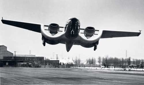
Photo 2 Caption
Front view of experimental plane with 75-horsepower engines.
It made take-offs and landings in less than 100 feet--upwind,
downwind, crosswind.
Photo 3 Caption
Readying six-foot channel for plywood skin prior to full-scale
laboratory trials to determine lift, drag, thrust and pitching
moment. Below, rear view of test model flown during Maryland
trials. Despite its unusual appearance, the plane's controls
are conventional and it is easy to fly.
Photos 4&5
Caption
Supersonic speeds are expected from the channel wing on
fighter aircraft.
Inventor's rough sketches showing adaptations of channel wing.
One has large propeller sweeping rear of channel formed by
section joining twin-fuselage fighter. Transport design uses
double channels on both sides.

Air Progress Magazine, October/November, 1964
Custer's Production Model Takes Bow
[ Original Article with Photos : Page 1 ... Page 2 ]
As a fitting example of independent, persevering aeronautical pioneering, on July 4th, the first production model of the 5-place Custer Channel Wing CCW-5 was rolled out of the company's hangar at the Hagerstown, Md., Municipal Airport, christened and demonstrated. Although this gleaming all-metal aircraft is entirely new, its design is not. Designer Willard R. Custer has spent 25 years in full-time research and development of the vertical lift concept embodied in the half-moon wing configuration. Single and twin engine scale models were built and test flown from 1927 through 1940; these were followed by test flights of single and twin engine aircraft from 1943 to 1952. The prototype twin-engine all metal CCW-5 (photo, upper left), flying since 1953, took off in less than 100 feet on its maiden flight, and the company reports that it has hovered at from zero to 11-mph, although the craft is actually a STOL type. (Remaining six photos here are of the latest Custer).
The Custer Channel Wing is unconventional in that its wing channels replace such conventional aerodynamic devices as wing flaps and slots to provide required lift. In the Custer system, the powerplant is suspended in the channel with the propeller at the trailing edge. By drawing the air through the semi-circular wing at high velocities, pressures over the curved lifting surface are decreased to a much greater degree than in conventional wing configurations.
Actually, the Custer utilizes a Boundary Layer Control effect to create its greater lift. According to Custer, conventional aircraft obtain lift coefficients of approximately 3 through the use of high lift devices, whereas the CCW craft have demonstrated power-on lift coefficients of 5. Designer Custer further claims 100% greater lift capabilities for his, using standard airfoil section, propellers and engines, compared to other aircraft using similar airfoil/power combination.
Depending upon climatic conditions and weight, the Channel Wing configuration permits the craft to take-off in distances ranging from a 75 foot ground roll, down to virtually zero length, although high temperatures (95 degrees) will boost the run to 250 feet.
The CCW-5 is conventional all-metal aircraft construction, except for the compound curve section of the channels, which are of fiberglass. The channels, a web and rib structure using a main and secondary spar, are made of aluminum. Each spar has two sets of cap angles. The ribs tie into the cap angles and web. The metal and fiberglass channel skins are wrapped around the ribs. The engines are suspended in the channels by tubular steel frameworks with the frames mounted to the wing spars and two pylons supporting each engine.
The Custer Channel uses a 4418 airfoil section with a 6 foot chord. Each propeller, located slightly aft of channel trailing edge, is a thin tipped 7 foot diameter full-feathering Hartzell with its tips trimmed. In rotation the tips deflect forward to close the channel; at 2625-rpm air is sucked through the channel over the airfoil at 115-mph to provide the BLC and lift effect. Designer Custer reports that about 15 years work went into his channel/propeller set-up.
The prototype CCW-5 utilized a redesigned Baumann "Brigadier" airframe; the production prototype was constructed from the same jigs. Later craft incorporates only a few changes, mainly fairings at the channel roots and configuration change of the wing trailing edge, plus latest version of the 260-hp Continental engines which were moved slightly aft. The CCW Corporation reports initial orders for 40 CCW-5's, 20 of which are slated for a West Coast distributor to be sold as executive and utility craft. FAA Type Certificate is expected by July 1965, at which time 6 to 8 craft should be well along on a production line. Price is $65,000 with standard equipment.
CUSTER CHANNEL WING CCW-5
Wing Span 41 ft. 2
in.
Length 28 ft. 8.5 in.
Height (at rudder) 10 ft. 10 in.
Height (at cabin) 6 ft. 9 in.
Cabin interior height 4 ft. 5 in.
Cabin interior width 4 ft. 5 in.
Empty weight 3675 lbs.
Gross weight 5400 lbs.
Top speed 200 mph.
Cruise speed 180 mph.
Minimum sustained level flight 35 mph.
Take-off run 50 to 250 ft.
Landing run 300 ft. (approx.)
Ceiling 22,000 ft.
Accommodation 5 seats
Engines--two 2600 hp. Continental O-470 with fuel injection
http://www.angelfire.com/va3/bythefire/AirPower_1.html
Airpower Magazine, Volume 7 No. 3 May, 1977, pp.8-19,58
The Custer Channel Wing Story
by
Walt Boyne
After forty years of pioneering a new concept of lift, Willard R. Custer's ideas are now in the forefront of STOL aviation!
Author's Note: The Custer Channel Wing concept, after almost 40 years of public attention, is still so controversial that this article must be written in two sections. The first covers development of the idea from 1927 to its present (and possibly future) status. The second presents the engineering opinions, pro and con, which have fueled the controversy. Both are included in this article.
Willard R. Custer is a man straight out of American folklore. He is the prototype Yankee inventor, smart, tough, resourceful, unafraid of the machinations of big government, big business, or fate. He believes in his invention, and he knows that sooner or later he will prevail.
Custer is a genuine innovator, for although designers have tried virtually every combination of wing size and shape, and every permutation of engine/propeller placement, it remained for him to combine the two elements in his famous Custer Channel Wing.
The inventor is a friendly, persuasive, energetic, single-minded man who has pursued a fifty year dream with a charming tenacity that has weathered many disappointments. He is convinced that he is right, that he has been right, and that the world has been denied the benefits of the Custer Channel Wing by a combination of misfortune, lack of vision, and, sadly in some instances, simple bad faith.
It's hard to be around Willard Custer for more than a few minutes before beginning to believe with him in his concept. He is so evidently sincere, so deeply convinced and so determined to win through that he converts even the most ardent skeptics--at least temporarily. He's an exhausting man to interview, for he flies around his small but neat shop/laboratory, grabbing an air hose to "fly" a screwdriver around to prove a point, picking up a 40 year old model, shoving a jet engine test rig out of the way, all the time telling you of the fundamental simplicity of his own science--"aerophysics"--and never tiring of the main topic of conversation, his patented channel wing.
In some respects these engaging characteristics may work against him in today's cold business climate. Times have changed, and aviation is more sophisticated, more finance oriented, and its engineering requirements are vastly more extensive. It may be that the very qualities which have sustained him in his battle against convention are not the ones which persuade a modern businessman to put up the necessary financing.
No matter; he has succeeded in his own mind, and the minds of many qualified engineers. More important, there are current indications that his concepts may yet be recognized.
The Custer saga began during a near-hurricane. A young Willard R. Custer was taking shelter in a barn, when suddenly the roof sailed off. Instead of being frightened, Custer wondered where the power to lift the roof came from. He'd been fascinated with aircraft for a long time, and knew that they had to accelerate down a runway to generate enough lift to take-off, while the barn roof, a poor airfoil, had lifted off "just sitting there".
Custer soon came upon a distinction that has eluded other inventors, postulating that when air passes over an object, as in the barn roof incident, that is "speed of air". However, when an aircraft flies through the air, that is "air speed".
Now don't just put this off as semantics, not just yet, anyway. It is Custer's theory, and it is best to use his words to describe it, i.e., "it is the speed of the air and not the speed of the object which counts. The airfoil was designed to obtain a reaction from the air mass through which it is moved. The [channel wing] was designed to obtain a reaction from the air mass moved through it."
In essence, Custer says that in his wing, the movement of air through the channels reduces air pressure in those channels, and that atmospheric pressure on the bottom of the channel airfoil then creates lift in direct proportion to the pressure reduction in pounds per square foot.
Other engineers have said it better for Custer, but his comments are essentially correct. In stricter terms, an engineer might say the following: "Greater lift coefficients are obtained by the effect of the propeller slipstream deflecting the air mass through which the wings are moved, by suppression of the boundary layer with high velocity slipstream, allowing the wing to fly at higher angles of attack before stalling, and by the vertical lift component due to the inclination of propeller thrust at high angles of attack."
I like Custer's way better.
Speaking again in more practical terms, the pusher propeller, tailored closely to almost touch the lip of the channel (Custer has experienced "channel shaving" in some of his experimental propellers) sucks air through the big half-tubes, and the Bernoulli principle does the rest. The propeller/channel juncture is critical, and some of the most efficient results have been obtained when the juncture was temporarily sealed by pouring water into the channel.
All of the above might sound like double talk, if Custer had not demonstrated his principle in several models and four full size aircraft, or if extensive testing had unquestionably refuted his claims.
Unfortunately, the testing has been ambiguous, and while it has not refuted the claims, neither has it sustained them. Part of the problem is that the tests have not been designed to prove or disprove the ability of the channel wing aircraft to perform, but have only investigated certain aspects which were amenable to contemporary testing techniques. Another part of the problem is that Custer has understandably maintained such tight control over his patents that full development programs have not been possible.
There are additional factors which will be covered in the second part of the article, which are more difficult to define. On the one hand, government reaction to Custer through the years has ranged from mildly patronizing to outraged; it is fairly evident from the correspondence that Willard Custer's native engineering talents didn't receive the same respect that would have been accorded an established manufacturer.
On the other hand, Custer has probably been too optimistic about the potential of his invention, while soft-pedaling some of the real problem areas. His reluctance to let professional engineers tell his story in objective, conventional, engineering terms, clearly delineating both advantages and disadvantages, has undoubtedly cost him some credibility.
As we shall see,
engineering opinion is still divided about the Custer Channel
Wing, but that doesn't inhibit an examination of the airplanes
themselves, which constitute a unique line in American
aviation.
Custer had translated his hurricane/barn roof idea into a
working model by 1928, and obtained his first patent by 1929.
At about the same time he coined the word "aerophysics" to use
instead of "aerodynamics" to emphasize his concept that it was
the removal of air pressure above the channel rather than the
movement of the airfoil that was important.
In 1937 Custer built a single engine model which demonstrated vertical lift, and by 1939 he had formed a corporation, the first of many business entities which would sustain the idea over the years.
In 1940 he was able to demonstrate a twin engine model to his potential stock holders, obtaining enough financing to begin construction of the first full size channel wing, the CCW-1.
This aircraft was (is, actually, for it is now in storage at the National Air and Space Museum's Silver Hill facility) an amazing combination of futuristic lines and modest test expectations. Custer is an excellent woodworker, and the streamlined fuselage and carefully built channels are beautiful examples of art.
The airplane had 202.5 square feet of wing area, spread over a most unusual surface. Semi-circular, detachable wing tips were added to a straight chord wing surface, for a total length of nine feet four inches; a six foot channel was attached between the outer panel and the fuselage. Total wing span was 32' 10-1/2 ". The channels were hung under the wing like huge nacelles, and the two Lycoming 75 horsepower four cylinder air cooled engines were mounted about midway in the channel. The 19'11" egg shaped fuselage seemed disproportionately short, and the aesthetics were not helped by a low aspect ration "T" tail empennage. The stumpy landing gear looked like an afterthought.
Yet, despite this unusual appearance, the CCW-1 logged more than 300 hours in a restricted test program aimed primarily at learning how the channels worked, and what new flying techniques were required to guide the channel wing.
Curiously, Willard Custer made the first flight in the aircraft on November 12, 1942, entirely inadvertently. Custer is not a pilot and his test pilot, E.Kenneth Jaquieth was not in town on the day financial backers came to the Custer laboratory to see the airplane. The backers wanted to take some pictures, and asked Custer to taxi the CCW-1 to the small field where Jaquieth had been conducting taxi tests.
The field was only about 200 feet away, up a slight hill, and Custer felt qualified to move the plane. He applied power to get up the incline, and was somewhat disconcerted to see the trees on the horizon disappear. He was airborne, a non-pilot on the first flight of a brand new kind of aircraft. Custer throttled back abruptly, and the CCW-1 settled in, bending the landing gear.
Instead of being upset, the backers were delighted, for their dark horse had flown, albeit briefly.
The CCW-1 was later flown in demonstration for the military at the Beltsville, Maryland airport, where gruff, hard boiled Brigadier General W.E. Gilmore was excited enough to authorize a test program. Custer recalls that Gilmore actually phoned Orville Wright, who was in Washington at the time, urging him to come out and witness the new development.
The testing program which began on June 6, 1944 proved to be typical of the entire series of government tests of the channel wing concept, generating mixed conclusions, controversy and zero satisfaction to anyone.
The report, Army Air Forces Technical Report No. 5142, concluded that the lift generated by the channel was similar to the increment of lift generated by normal slipstream velocity in conventional wing/propeller arrangements. Unfortunately, the conclusion did not restate the point made in the report that the channel generated more lift than the conventional arrangement. The report stated further that while the channel was markedly inferior to the helicopter in producing static lift, it was superior to conventional wing-propeller arrangements in this regard, and in producing lift with forward velocity.
The final conclusion was startling, for the report stated that "the device does not show sufficient promise of military value to justify further development by the Army Air Forces." This is surprising in that the improvement of static lift over a conventional wing/propeller arrangement was marked, and high lift devices in the form of flaps, slats and slots were under intensive development at the time.
The verdict typified the testing process, which never validated or denied what should have been the basic question, i.e. "Did the channel wing have characteristics of sufficient value when compared to other high-lift devices to warrant further development?"
Instead, the government denied that the channel wing was as good as a helicopter, and Custer compounded the problem by insinuating that it was indeed as useful as a helicopter.
Custer made an immediate and lasting interpretation of the test results, one which did not help the controversy. He inferred that perhaps the results were too good, and might actually be a threat to the then infant helicopter industry, which was receiving tremendous backing from the armed services. The first reaction to a charge like this is to shrug -- it sounds too much like the stories of "60 miles per gallon carburetors" which have allegedly been suppressed over the years. Yet there are other arguments which makes (sic) one wonder.
The most cogent of these are the later Wright Field tests, conducted in 1945 and 1947, which were cautiously optimistic about the channel wing concept. There is also the testimony of the Wright Field engineer, Don Young, who conducted the tests. He testified in a Washington Federal District Court that the channel wing was in fact capable of direct lift, and largely as a result of his testimony, Custer was granted additional patents.
These optimistic test interpretations are reinforced by results from independent engineering firms which have investigated the theory and found it to have merit.
The brutal truth is that the government would have rendered itself and Custer an inestimable service if it could have structured tests which would have proved, beyond any shadow of a doubt, that the channel wing was either (A) absolutely worthless or (B) had some promise. In case A, Custer could have turned to other things, while in case B, he might have been able to obtain adequate capitalization.
Custer persisted, however, and built an engineering test vehicle, the CCW-2, in response to some of Young's test report recommendations. The CCW-2 used a Taylorcraft fuselage and empennage, with six foot channels in lieu of wings. Conforming to Young's suggestions, the channels were shorter, and the propeller was placed at the extreme rear edge of the surface. The CCW-2 was extensively tested in free flight, tethered, and in the NACA wind tunnel.
Harold R. Custer, Willard's son, made the first flight of the new aircraft on July 3, 1948. Harold is as energetic and determined as his father, and has the unique distinction of having logged more channel wing time than any other pilot -- over 1,000 hours.
Harold totaled 100 hours flying time in the CCW-2, which could take off in 45 to 65 feet, and land in the same distance. Lateral control of the wingless vehicle was obtained by differential use of the throttles.
The flight test program was not without its highlights. The C.A.A. insisted that wings be mounted on the test bed, and short stubs were attached. These neither helped nor hindered the aircraft, according to Custer, but did mollify the bureaucracy. More significantly, the aircraft demonstrated vertical lift in zero wind conditions, while tethered.
The wind tunnel tests at Langley are another subject of controversy and conjecture. Apparently the tests were well conducted, and the results reported accurately. Unfortunately, the conclusions seem to have been erroneous. Critics of the report indicate that it stated the primary increment of lift came from thrust, rather than from the lift, due to increased velocity in the channels, even though the plotted data showed this not to be the case. Also, the conclusions dealt with the CCW's hovering characteristics, rather than its STOL (short takeoff and landing) characteristics, an unfortunate view, for the channel wing was clearly designed for STOL, not helicopter style operation.
During the whole arduous process of design and testing, one thing definitely was not happening. Willard R. Custer was not making a lot of money; he has invested not only all of his own funds, but all of his life in the channel wing, and the material rewards to date have been small.
But Custer's tenacity and his almost messianic belief in his program enabled him to secure backing from a series of investors, and in 1951 he was able to employ the Baumann Aircraft Corporation to modify a Baumann Brigadier to the CCW configuration.
The result was the prototype CCW-5, a rather handsome five place aircraft using two Continental 0-470-A engines of 225 horsepower each. The standard Baumann fuselage and empennage were retained, and a 41 foot span wing with two seven foot wide channels was attached.
First flight of the CCW-5 took place on July 13, 1953, with Walker J. Davidson at the controls. The company then spent the next several years performing demonstrations for civil and military audiences. These demonstrations consisted largely of maximum performance take-offs, with a terrifyingly steep climb out, using steep turns to the right and left at a high angle of attack and at speeds well below the stall speed of conventional aircraft to impress the audience. Motion pictures of the demonstration are heart-stopping; you know that an aircraft in that attitude, at that altitude and airspeed, is going to crash -- but the CCW just keeps on turning.
Slow flight was a specialty, with speeds as low as 22 mph being measured. On August 27, 1954, in a remarkable display of the channel wing's ability, the CCW-5 was actually hovered against an 11 mph wind. The demonstrations would then conclude with a steep approach, an incredibly short landing, with the turnoff not at the first intersection, but at the approach end of the runway.
Take-off technique is critical in the CCW-5, for the pilot has to rotate sharply after the first 100 feet of roll, so that the high velocity air stream passing through the channel does not bounce off the runway against the undersurface of the horizontal stabilizer. If this happens, the nose can be forced down, considerably lengthening the take-off roll.
The prototype CCW-5 had an empty weight of 3,000 pounds, a gross of 4,925 and a maximum gross of 5,400 pounds. Maximum speed was quoted at 200 mph, with a 180 mph cruise; these were probably optimistic figures, but most manufacturers tend to err on the bright side.
The performance of the aircraft was good enough to interest several firms in its manufacture, the most promising being the Custer Channel Wing (Canada) Ltd., which secured the rights from the Custer-Frazer Corporation, and planned to build the plane in association with Norduyn Aircraft, Ltd. The short field capability of the CCW-5 was attractive to bush pilots, and an initial production run of 100 was planned.
This operation, like several other potential manufacturing plans, fell through, primarily because of problems synchronizing FAA approval of the aircraft, and SEC approval of the financing.
Custer undertook to build the 1st production CCW-5 at Hagerstown, Maryland, using Baumann Brigadier drawings as a start point, but modifying these as necessary to suit the different construction and stress requirements of the channel wing configuration. This, the fourth channel wing airplane, was rolled out on July 4, 1964, and it appeared that after many years of struggle the Custer Channel Wing was finally going to be marketed.
Fate intervened in the form of the Securities Exchange Commission, which took exception to the manner in which the corporation stock had been issued, and the rug was pulled out from under the venture.
The production aircraft was outwardly similar to the prototype, but building it from the ground up rather than converting existing Baumann components permitted considerably reducing drag. There were external differences, too; the engine nacelles were more streamlined, the wing had 2" less span, the nacelle strut bracing was simplified, the ailerons were moved further outboard on the wings, and rudder and aileron travel were increased slightly.
In the steps toward FAA certification, it became necessary to raise the position of the horizontal surfaces, which impaired STOL performance. As previously noted, the CCW pilot has to get the horizontal surfaces below the vectored slipstream as soon as possible for optimum results.
Performance figures for the production CCW-5 varied little from the prototype, with the same top end performance indicated. Power on stalling sped was listed as 22 mph, initial rate of climb, 1,600 feet per minute, with a 22,000 foot service ceiling.
A single engine service ceiling of 5,000 feet was obviously a limiting factor in performance, and Custer planned to remedy this with improvements in the propeller/channel trailing edge juncture. A moveable sleeve has been suggested, one which would maintain a tight seal at the channel for STOL work, but which could retract for higher cruise performance.
And so engineering rears its ugly head again -- if the advantages of the CCW derive from the channel section with its relative lack of mechanical complexity compared to slots and flaps, what does the addition of a moveable surface do? This and other similar questions will be covered in the engineering discussion.
Where does the program stand now? It still has its advocates, and there have been proposals for putting channels on everything from Curtiss C-46s to Fairchild F-27s, to executive jets. As indicated above, there is a real possibility that full scale testing of the production aircraft by a government agency will take place. But whatever occurs, you can be sure that Willard R. Custer will not stop fighting the good fight, nor will he be convinced that his discovery is not, still, the coming thing.
The engineering side -- pros and cons.
It is surprising to discover how sensitive and controversial the Channel Wing is today, after all its many years in the public eye. In an attempt to determine what the real merit of the Channel Wing is, I went to several engineers who had taken part in the testing and development of the device over the years. I interviewed participants of three different kinds. First were government representatives who had either conducted or interpreted the official tests. Second were engineers who had seen development potential in the channel wing, and who had a positive interest in its commercial success. Third was an engineer who was completely objective having neither a financial or government interest.
Because of the controversy, and because some legal action may still be forthcoming, I've been asked not to name the participants involved.
The Pro Side: Proponents of the Custer Channel Wing say that first of all, the true capabilities of the idea were not susceptible to test because appropriate engineering theory had not yet been developed to explain its demonstrated performance. In other words, the airplane was physically doing things for which aerodynamic formulas had not yet been evolved at the time of testing. Such formulas have since been developed, and further testing could be done in a more scientific manner.
Because adequate theory was lacking, the CCW was tested for features and modes of flight which were in reality peripheral to its main intent, simply because there was theory to test these items.
The pro-channel wing faction maintains that the channel wing's pusher propeller arrangement not only forces circulation over the airfoil, taking advantage of the Bernoulli principle, but it also minimizes loss due to reverse flow around the trailing edge, and then across the ventral surface.
The NACA tests, they say, erroneously failed to reveal that the principal source of lift is due to the increased velocity in the channels, and further, the tests should have highlighted the findings that the static lift exceeded the weight of the test vehicle. This basic fact underlies the most salient advantages of the Custer Channel Wing, its simplicity, and its ability to operate in the STOL mode without expensive high lift devices.
The initial cost of the Custer Channel Wing aircraft -- of any type -- is probably slightly greater than a conventional aircraft of the same type, but less than that of an equivalent STOL aircraft using flaps, slots, etc. Its advantage stems from the fact that its operating costs would be far lower than those of the STOL alternative, because of the lessened maintenance requirements. Its greatest advantage, however, lies where it can be employed in helicopter operations, i.e. those situations in which helicopters are presently used, but with suitable modification in technique or landing area, a CCW could be substituted. The reason for this, of course, is the horrendously high cost of helicopter operation.
The CCW could be used for larger aircraft, and with jet engines. The increased drag of the channel wing undoubtedly would reduce top speeds, but in the correct application this would not be significant. "Correct application" includes STOL airline transportation over relatively short stage distances; use in remote areas where the ability to fly in and out of short airstrips with heavy loads is important, or where revenues dictate against the use of a high operating cost vehicle.
In sum, the CCW proponents say that the concept provides an economic, efficient solution for certain applications that are not presently met by conventional STOL aircraft or helicopters.
The Con Side: Those who take a negative view of the Custer Channel Wing do so persuasively and authoritatively. Their initial reaction is usually: "Oh no, not the channel wing again," followed by a measured explanation that there is not and never has been any emotional or economic prejudice against Custer's ideas. If, they say, the Channel Wing had shown merit, it would have been in the national interest to develop it, and it would have been so developed.
In more specific terms, the opponents of the Channel Wing say that it has less potential now than when it was first evaluated and found to be inferior to other approaches to STOL performance. The anti-Custer group concedes that the channel wing's lack of flaps results in a simpler, more economic system, and that the generation of high lift by the configuration is accompanied by a low pitching moment compared to conventional wing/flap arrangements.
The virtually viceless stall of the CCW is also acknowledged, as is the fact that ground personnel are exposed to less hazard by the propellers shielded by channels than by conventional propellers.
These are about the only advantages, however, and there are more than off-setting drawbacks, which the anti-CCW view lists as follows:
(a) Higher aerodynamic drag due to the increased wetted area resulting from the channels and, particularly, from the juncture of the channel to the fuselage.
(b) The very simplicity of the CCW arrangement prevents changing the wing aerodynamic characteristics to different modes of flight. In other words, the thicker CCW is optimized for one mode, while a wing with a well designed flap can be optimized for both slow flight, cruise and higher speeds.
(c) The requirement for cross shafting of the engines to avoid uncontrollable assymetric forces in the event of an engine failure when at a low airspeed, high angle of attack flight condition. (Custer concedes that production aircraft will be cross shafted.) This requirement of course dilutes the CCW claim for simplicity.
(d) A substantially lower power-off lift coefficient compared to a conventional wing/flap arrangement. This means a higher landing speed is required for a power-off landing. (Custer counters this with statistics on the relative infrequency of power off landings in any multi-engine aircraft.)
(e) Increased structural complexity of the wing.
(f) A lack of engineering investigation into the problems of stability and control, and the use of rather simplified engineering theory to explain the complex CCW aerodynamics. (This, as noted above, is a two-edged sword.)
So there you have it. Two points of view, both basically honest, and both vulnerable to the assertion that the CCW has not been amenable to really valid testing.
What is the answer? Perhaps the future will tell, for more testing, presumably this time with more sophisticated techniques, is in the offing. It will be interesting to see, after all these years, who is really right.