Thorsten DENK
Solar Reactor
Solar Reactor
http://www.dailymail.co.uk/sciencetech/article-5025197/Astronauts-make-water-oxygen-MOON-ROCKS.html
Solar-powered machine could let
astronauts make their own water and oxygen from MOON ROCKS
Solar-powered
machine could use lunar soil collected by robots on the moon.
It would extract water from the soil, then obtain oxygen
with further processing. It would only require oxygen
from Earth at start, cutting down payload weight
By
Cheyenne Macdonald
An aerospace engineer has developed a solar reactor that could allow astronauts to make their own water and oxygen on the moon.
The system can extract water from lunar soil, and would only require hydrogen brought from Earth for its initial use – after the first few hours, hydrogen would be recycled from then on.
As hydrogen is far lighter than oxygen, the system could dramatically cut down on the weight of a mission to the moon.
The machine has now completed a six-month test run, and according to the creator, it could make enough oxygen and water to supply up to eight astronauts.
The solar-powered system can extract water from lunar soil, and would only require hydrogen brought from Earth for its initial use – after the first few hours, hydrogen would be recycled from then on.
THE NEW MACHINE
The process uses the iron-titanium oxide ilmenite (FeTiO3), which is found in the ‘dark’ areas of the moon.
This could be dug up by a lunar robot, and carried over to the reactor, according to Denk.
Lunar soil, unlike soil on Earth, does not experience weathering, as the moon does not have an atmosphere.
So, the particles are oddly shaped and have jagged edges.
Before use, they would need to be pre-treated to smooth them out, then sieved to obtain the right grain size.
And, it would only require hydrogen brought from Earth for the initial processing.
Afterwards, this would be recycled.
According to Denk, the machine can process a 25kg particle load in under an hour.
In just one hour, it can make 700kg of water – and, in four hours, it could produce 2.5 kg of oxygen, all using under 10 kW of electricity.
Researchers have been working for decades to come up with ways to make oxygen on the moon.
‘From the beginning people were thinking this probably has to be done with a solar furnace, because on the moon there is not very much to heat a system that you can use; photovoltaics with electricity or a nuclear reactor or concentrated solar radiation,’ said Thorsten Denk, who worked on the device for 10 years at the Plataforma Solar de Almeria (CIEMAT).
‘After the Apollo missions, scientists had a lot of ideas of how to make oxygen on the moon, because every material that you bring from Earth costs money.
‘For every kilogram of payload you need hundreds of kilograms of fuel.’
Denk’s reactor can split water from the lunar soil, which can then be further split into oxygen and hydrogen.
And, the machine he’s built is the real size of what could be built on the moon to support a crew of 6-8 people.
It currently weights 400 kilograms, but could be reduced with further refinement, Denk says.
‘The hydrogen would be just for the first few hours. Then that would be recycled with the electrolyzer,’ he explained.
‘Even if you bring hydrogen from Earth and get oxygen from the Moon for making rocket fuel, you save nearly 90% of the weight.
‘Hydrogen is the lightest element. Oxygen is much heavier.’
The moon experiences long periods of sunlight, followed by long periods of darkness - and, the conditions are ‘ideal’ for making solar fuel, according to Denk.
‘Daylight is 2 weeks without interruption, and then you have the same half-month of dark as night. So if you need three hours to turn it on, it's not a big problem,’ Denk said.
‘There is no atmosphere on the Moon, and there is no weather, no clouds, so you really can operate from sunrise to sunset at full power for each half-month.’
Solar furnaces require very high temperatures – but, they can’t be too high as to make the lunar soil ‘gum up’ and stick together, in what’s known as sintering, the creator explain.
‘The chemical reaction starts to be working from 800°C but sintering starts to be a problem at 1,050°C degrees, so my goal was not to surpass the 1000°C,’ he explained.
‘I achieved a bit more than 970°C and the maximum was hardly above 1000°C.
‘So I had a temperature in the bed of not more than 30° up and down, for the highest possible average temperature without sintering.’


http://www.solarpaces.org/wp-content/uploads/Thorsten-Denk-Design-and-Test-of-a-Concentrated-Solar-Powered-Fluidized-Bed-Reactor-for-Ilmenite-Reduction.pdf
Design and Test of a Concentrated Solar
Powered Fluidized Bed Reactor for Ilmenite Reduction
Thorsten Denk, Aurelio González-Pardo, Inmaculada Cañadas. Alfonso Vidal
Thorsten Denk, Aurelio González-Pardo, Inmaculada Cañadas. Alfonso Vidal
[ Karrick Low-Temperature Carbonization ]
http://scholar.google.com/scholar_url?url=https://www.researchgate.net/profile/Alfonso_Vidal/publication/265612532_UPSCALING_OF_A_SOLAR_POWERED_REACTOR_FOR_CO2-FREE_SYNGAS_AND_HYDROGEN_PRODUCTION_BY_STEAM_GASIFICATION_OF_PETROLEUM_COKE/links/5416c5b80cf2fa878ad42770.pdf&hl=en&sa=X&scisig=AAGBfm3BO7n4nwm_ULw8tzFdxL-J_qsfeQ&nossl=1&oi=scholarr
Upscaling of a SolarPowered Reactor for CO2-free
Syngas and Hydrogen Production by Steam Gasification of
Petroleum Coke
Thorsten Denk, et al.
Thorsten Denk, et al.
US2011232635
CONCENTRATED SOLAR RADIATION ASSEMBLY
CONCENTRATED SOLAR RADIATION ASSEMBLY
Radiation receiver incorporates a radiation entry window which is installed into the boiler wall in such a way that mechanical stresses in it are reduced by its displacement relative to the boiler wall
BACKGROUND OF THE INVENTION
[0001] This invention relates to a solar energy concentrating and collecting assembly, that is to closed central assembly systems for concentrated solar radiation, even more particularly, to a refrigerated window for a large-scale concentrated solar radiation assembly or structure.
[0002] Concentrated solar power systems focus direct solar radiation through optical devices onto an area where a assembly is located. The assembly transforms the radiation into heat. Since concentrated solar power systems produce both heat and electricity, they can replace all or part of the energy requirements in some industrial applications. On the small scale, they also have durability and low operating costs.
[0003] Various solar energy collection arrangements are known. Many utilize an assembly with a receiver located at the focus. The receiver or central solar radiation assembly absorbs concentrated sunlight at high temperatures, commonly about 700°-1500° C. and transfers the heat generated by the solar absorber to a working fluid, which either serves as a heat carrier fluid or is designed to perform a thermochemical process. In one known kind of central solar assembly, a so-called tubular assembly, the working fluid flows inside tubes located usually near the inner periphery of the solar assembly housing. In such a assembly, solar radiation is absorbed at the outer surface of the tubes and is transmitted as heat to the working fluid, which is thus heated. The overall resistance to heat transfer and the ensuing heat loss in such tubular central solar assemblys is relatively high.
[0004] High temperature closed solar assemblies generally have a cylindrical housing. Closed solar assemblies are closed at one side by a transparent window to form a sealed recipient capable of holding a working fluid or a chemical reaction mixture in direct contact with the absorber while avoiding physical contact between the working fluid and the ambient air. The sealed recipient also protects against temperature loss. In operation, the working fluid or reaction mixture is forced to flow across the assembly chamber whereby heat is transferred from the absorber to the fluid and is utilized for the chemical reaction or is transported outside the assembly.
[0005] The transparent window that shields the absorber in a solar assembly must be capable of sustaining the extreme conditions of high solar flux, high temperature and in some applications pressure associated with the conditions of operation. Solar assemblies designed for large-scale solar energy conversion systems need large transparent windows. These windows with the necessary dimensions and the required optical/thermo mechanical qualities are not readily available. Since large pieces must be made to order and the requirements concerning mechanical stability increase with size, these windows are extremely expensive or even impossible to manufacture. As a result, there is a need for improved large-scale solar assembly windows and large-scale concentrated solar power systems.
SUMMARY OF THE INVENTION
[0006] The primary object of the present invention is the creation of an improved solar assembly window for a central solar assembly that fulfills the requirements of a large central assembly in terms of efficiency, thermal and mechanical loads.
[0007] It is a further object of the present invention to provide a concentrated solar radiation assembly.
[0008] In accordance with the present invention, a large-scale concentrated solar radiation assembly is disclosed. The concentrated solar radiation assembly comprises a housing divided into segments by housing trusses; window blocks positioned within the segments supported by the housing trusses; and, internal trusses positioned on top of the window blocks and within the segments. The housing trusses and internal trusses are hollow and define cooling channels for flow of cooling liquid, such as water or the like.
BRIEF DESCRIPTION OF THE DRAWINGS
[0009] A detailed description of preferred embodiments of the present invention follows, with reference to the attached drawings, wherein:
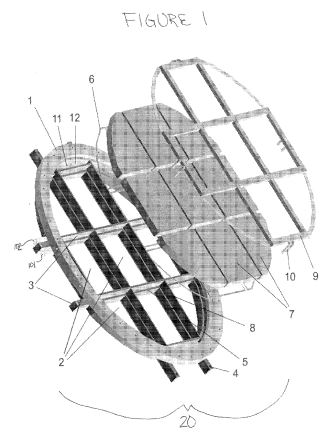
[0010] FIG. 1 illustratively depicts a non-limiting example of the individual components of the concentrated solar radiation assembly as claimed.
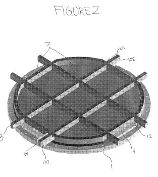
[0011] FIG. 2 illustratively depicts a non-limiting example of the outside, solar radiation side, of the assembled concentrated solar radiation assembly as claimed.
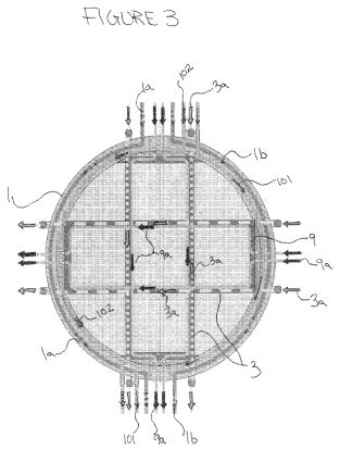
[0012] FIG. 3 illustratively depicts a non-limiting example of the inside liquid flow of the concentrated solar radiation assembly as claimed.
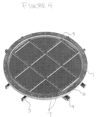
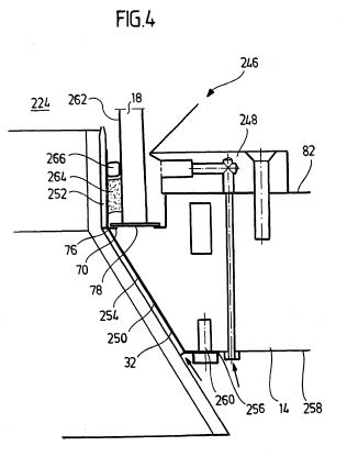
[0013] FIG. 4 illustratively depicts a non-limiting example an assembly/structure fluid side, of the assembled concentrated solar radiation assembly as claimed.
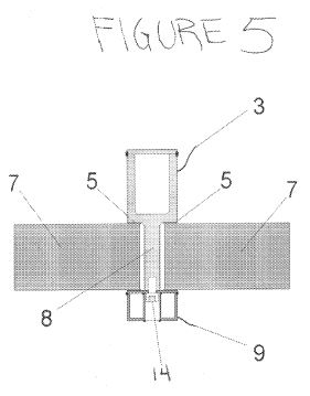
[0014] FIG. 5 illustratively depicts a non-limiting example of the hermetic seal of the assembly/structure as claimed.
DETAILED DESCRIPTION
[0015] The invention relates to a refrigerated window for a large-scale concentrated solar radiation assembly or structure. The window is divided into several segments that are shaped to keep the assembly hermetically sealed. The hermetically sealed assembly, including the window, is able to withstand thermal and mechanical loads caused by the highly concentrated solar radiation, very high temperatures, and the pressure difference between the interior and the exterior. Outside trusses define the shape of the window segments. Window segments are held within the segments by a housing and the outside trusses. The outside trusses apply the force needed to hermetically seal the assembly. In addition, the outside trusses are shaped to resist mechanical load and are water cooled to resist thermal load.
[0016] FIG. 1 depicts a non-limiting embodiment of the present invention. FIG. 1 shows an exploded view of a large-scale segmented refrigerated or water-cooled window assembly 20 for highly concentrated solar radiation. Solar radiation enters from the left of assembly 20 and the structure is on the right of assembly 20. The window for a large-scale concentrated solar radiation assembly or structure is divided into several segmented window blocks 7, which can be made of glass, such as quartz glass, or other suitable materials that are well known within the art. Large-scale as used herein may be defined as an assembly having a window where size makes durability of the window assembly an issue, for example, where the window diameter or similar dimension is larger than about 400 mm. In order to withstand the unavoidable mechanical loads and to solve the fabrication problems associated with larger sizes, the window is divided into several segments that are refrigerated by liquid cooled trusses.
[0017] High mechanical load as defined herein is a function of pressure difference and temperature level. Pressure differences of 2 bar, such as from ambient (1 bar) to 3 bar is considered a high mechanical pressure load. Temperature above about 1000° C. is considered high mechanical temperature load. The mechanical pressure and temperature load can be increased up to an unknown limit by reducing the spacing between the trusses and/or increasing the thickness of the trusses and glass-blocks. In theory, the window blocks of the present invention can handle mechanical loads that reach beyond the practical limitations of the window blocks, i.e. window blocks as big as football fields may be manufactured to withstand high mechanical loads; however depending upon their intended use, window blocks of such size may not be practical.
[0018] Continuing on FIG. 1, the window blocks 7 are supported by outer trusses shown here as horizontal and vertical housing trusses 3. The horizontal and vertical orientation of the housing trusses 3 helps to sustain mechanical load possibly caused by the pressurized surface of the windows. An annular liquid-cooled flange 1 is divided into segments 2 by the housing trusses 3. A cooling liquid enters the housing trusses 3 through housing truss liquid inlets 4. The cooling liquid, such as water, may be any liquid that is well known within the art.
[0019] The housing trusses 3 are shaped to include a support surface 5. The support surface 5 supports the window gaskets 6, the window blocks 7 and an upstanding rib 8. Upstanding rib 8 provides support for the internal trusses 9 and spacing for the window blocks 7. The internal trusses 9 are connected to the rib 8 of the external trusses 3 with countersunk screws 14. As shown in FIG. 5, the window blocks 7 are captured between support surface 5 of the housing trusses 3 on one side and internal trusses 9 on the other side. The countersunk screw 14 into upstanding rib 8 applies sufficient force between housing truss 3 and internal truss 9 to hermetically seal the window 7. The hermetic seal is also effectuated by a soft ceramic material (not shown) between inner truss 9 and window block 7. The soft ceramic material equalizes the pressure on the window blocks 7 exerted by the support surface 5. The soft ceramic material may be any soft ceramic that is well known within the art, such as ceramic fabric.
[0020] Attached to the internal trusses 9 are liquid inlets 10. The liquid inlets 10 of the internal trusses 9 are connected to liquid inlet holes 11 in flange plate 12. Housing truss liquid inlets 4 and flange plate liquid inlets 11 allow a cooling liquid to flow through the hollow housing trusses 3 and hollow internal trusses 9. The advantageously orientated trusses are thus cooled by liquid flow. The cooled trusses are able to withstand the increased thermal load and temperature caused by the highly concentrated solar radiation.
[0021] The solar radiation assembly of the present invention may incorporate varying geometries. The differing assembly components, including window segments as detailed above, may have differing shapes,
sizes and/or orientation. For example, the window segments can be round, square, rectangular and hexagonal. The corresponding internal and external trusses may be orientated around the shape of the window segments. Further, the window segments of the present invention can be used in large-scale systems as described above, and also in small-scale systems. The accompanying figures and detailed disclosure are in no way limiting to the geometries of the components that, as assembled, complete the solar radiation assembly and/or structure of the present invention.
[0022] FIG. 2 illustratively depicts a non-limiting example of the outside, solar radiation side, of the assembled concentrated solar radiation assembly. This side of the assembly is exposed to solar radiation, i.e. sunlight, which is collected through the window segments 7. As depicted in FIGS. 2 and 3, there are a total of twelve cooling water flows: one (3a) through each of the four outer trusses 3; one (9a) through each of the four inner trusses 9; there are two through the flange 1 wherein one (1a) flows through the upper half of flange 1 and one (1b) flows through the lower half of flange 1; and finally, two (101 & 102) flow through the curved outer trusses welded to flange 1.
[0023] FIG. 4 illustratively depicts a non-limiting example of the inside, assembly/structure fluid side, of the assembled concentrated solar radiation assembly. This side of the assembly is not exposed to direct solar radiation. This side is exposed to heat from the inside of the assembly.
[0024] The segmented refrigerated windows of the present invention may be pieced together into an inexpensive large-scale solar energy conversion system.
[0025] The resultant segmented refrigerated window for large-scale solar assemblies/structures may be installed by any method, which is well known within the art. The solar assemblies/structures of the present invention are designed for large-scale solar energy conversion systems; however, they may also be employed in small-scale solar energy conversion systems. The segmented hermetically sealed refrigerated windows may be created in an unlimited amount of necessary dimensions. The shapes of the components illustrated in FIGS. 1-4 are the preferred embodiments of the present invention; however, regardless of the size or shape, the solar assembly of the present invention is able to withstand the optical load, thermal load and mechanical load needed for large-scale concentrated solar radiation receiver systems.
[0026] The large-scale concentrated solar radiation assembly and/or structure of the present invention may be implemented in other possible applications. The final physical and chemical characteristics of the solar radiation assembly and/or structure of the present invention may be applied to conventional energy technology, renewable energy technology, industrial heat process technology, conventional cementing technology, thermo chemical process technology, and any application that may benefit from the energy or heat generating properties of the present invention.
DE4336503
Apparatus and process for carrying out endothermic chemical reactions
Apparatus and process for carrying out endothermic chemical reactions
In order to create an apparatus for carrying out endothermic chemical reactions involving participation of particles, comprising a reaction vessel in which the particles can be heated by electromagnetic radiation, in such a manner that an optimised matching of the absorbed radiation power to an essentially complete gasification of the carbon-containing material is possible, it is proposed that the reaction vessel has a heating zone in which absorber particles or absorber particles and the particles can be heated by direct absorption of the radiation and that the reaction vessel has a delay zone in which the absorber particles give off heat to the particles in order to maintain the chemical reaction.
The invention relates to a device for carrying out endothermic chemical reactions involving particles, comprising a reaction vessel in which the particles can be heated by electromagnetic radiation.
In the context of research projects, for example, the gasification of oil shale using electromagnetic radiation as a carbonaceous material in stationary fluidized beds on a laboratory scale was studied, the fluidized bed apparatuses were irradiated from the outside.
The problem with these known solutions is that they are less efficient on an industrial scale.The invention is therefore based on the object to provide a device of the generic type, in which an optimized adaptation of the absorbed radiation power to a substantially complete gasification of the carbonaceous material is possible.
This object is achieved in a device of the type described above according to the invention that the reaction vessel has a heating zone in which absorber particles or absorber particles and particles can be heated by direct absorption of the radiation and that the reaction vessel has a residence zone in which the absorber particles heat to the Particulate to sustain the chemical reaction.
The solution according to the invention is thus to be seen on the one hand to absorb the radiation in a suitable manner and on the other hand then to make the heat so long available to the particles that they are capable of the best possible chemical reaction.
The advantage of the solution according to the invention is in particular the fact that on the one hand in the heating zone, heating of absorber particles or absorber particles and particles takes place and then the stored heat in the absorber particles is a sufficiently long time available to the endothermic reaction process with the particles sufficient To provide large amount of heat available and thereby achieve a substantially fully continuous reaction with the particles.
The heating zone can be designed differently. For example, it would be possible to convey the absorber particles over a horizontal distance in the heating zone.
However, it is particularly advantageous if the heating zone has a falling section through which the radiation passes for the absorber particles or the absorber particles and particles. The advantage of a heating zone formed in this way is the fact that the particles fly freely through the drop zone and thus there is no need to keep the particles strongly heating up in the heating zone in thermal contact with a complex, temperature-resistant conveyor and thus lose heat.
In principle, it would be in the case in which absorber particles and particles pass through the heating zone, conceivable to lead them so that they separated, that is, for example, in the form of separate case stretch the heating prevail.
However, it is particularly advantageous if the particles and the absorber particles mixed with each other pass through the heating zone and thus before the heating of both the absorber particles and the particles, a mixing thereof, so that after the heating zone in a simple manner, without further measures, the further reaction the particles in the residence zone due to the uniform mixing with the absorber particles can be done.
Preferably, mixing of the absorber particles and the particles is achieved in that the absorber particles and the particles are mixable in a mixing zone arranged upstream of the heating zone. The mixing zone is preferably formed by a mixer which converts the two free-flowing particle streams into one another.
In principle, the solution according to the invention could work in such a way that the absorber particles and the particles or residues thereof leave the reaction vessel together after the residence zone.
It is particularly useful, however, if the absorber particles are guided in the reaction vessel in a cycle through the heating zone and the residence zone, since this eliminates the need to supply large amounts of absorber particles through suitable locks, for example, to the reaction vessel and remove it.
For this purpose, it is preferably provided that the absorber particles can be brought to the heating zone from a discharge following the dwell zone in a return conveyor device.
This feedback can be formed in various ways. For example, this return conveyor can work mechanically. However, it is even more advantageous if the return conveyor device works with a conveying gas, because this avoids the problems of moving parts at high temperatures.
Furthermore, it is provided in the case of working with conveying gas return conveyor that the return of the absorber particles leads to a separator which separates the conveying gas from the absorber particles.
Preferably, the separator is arranged following the return conveyor and produces a free-falling absorber particle layer.
In order additionally to achieve a preheating of the absorber particles in the return conveyor, it is preferably provided that the return conveyor is also heated by the radiation.
A particularly advantageous embodiment provides that the return conveyor has a radiation absorber surface.
In theory, the radiation absorber surface could be arranged so that it is acted upon separately from radiation, while at another point in the reaction vessel, the absorber particles alone or as a mixture with the particles are also exposed to radiation.
However, it is particularly advantageous if the absorber particles or the absorber particles form an absorber curtain with the particles in front of the radiation absorber surface of the return conveyor device.
This absorber curtain is preferably selected to be so thin that the radiation which does not impinge on the absorber particles or particles strikes the radiation absorber surface of the return, and heats the absorber particles returned in the recycling so that no radiation energy is lost.
In the simplest case, the return conveyor is designed such that it has a return duct whose front side facing the radiation forms the radiation absorber surface at least in the heating area.
With regard to the formation of the dwell, no further details have been given in connection with the previous explanation of individual embodiments. Thus, an advantageous embodiment provides that the residence zone is formed in the reaction vessel of a dwell, this dwell is preferably designed so that it traps the moving through the heating zone absorber curtain, formed from the absorber particles or the absorber particles and the particles.
Preferably, this dwell is designed so that in this the absorber particles and the particles form a bed in which the absorber particles and the particles are directly in preferably köperlichem thermal contact with each other.
Alternatively, however, it is also conceivable to provide the dwell zone as a further drop or conveyor line for absorber particles and particles in which they move.
Since the residence zone constantly new absorber particles and particles are supplied, it is necessary to remove them again from the dwell zone.
For this purpose, preferably a discharge for the absorber particles and the remainder of the particles remaining after the gasification is provided.
In the case of an indwelling container in the simplest case, the discharge is designed so that it forms a channel leading away from this, preferably a channel following the direction of gravity.
Furthermore, in order to be able to feed absorber particles back to the recycling device after the residence zone, a separator is preferably provided downstream of the residence zone which removes at least part of the residues of the particles after the chemical reaction.
The particles can either themselves carry a substance that undergoes an endothermic chemical reaction. However, it is also conceivable that the particles themselves constitute a catalyst which, when heated by the electromagnetic radiation, serves to catalyze chemical reactions.
The solution according to the invention is particularly well suited when the chemical reaction is a gasification reaction in which a product gas is formed.
As materials for the particles, preference is given to carbonaceous materials whose carbon is gasified.
A particularly advantageous embodiment of the solution according to the invention provides that the absorber particles are ash particles, for example gassed particles, so that no exact separation between the residues of the particles and the absorber particles is carried out, but the ash collecting in the dwell zone is discharged to the same extent in the measure in that new ash is formed in the residence zone, while the remainder of the ash particles are passed as absorber particles via the return to the heating zone where they heat up due to the radiation and then transfer their heat to the particles in the residence zone, for example to maintain the gasification process of the particles to obtain.
In the solution according to the invention, for example, the conveying gas for the absorber particles could be an inert gas. However, this would have the disadvantage that the inert gas is always in turn to be separated from the product gas produced during the gasification of the particles.
For this reason, it is particularly advantageous if product gas is used as conveying gas, so that no complicated separation between the conveying gas and the product gas in the reaction vessel is required, but a common discharge of product gas can be provided, from which in turn conveying gas is recovered.
With regard to the heating zone, it has hitherto only been stated that the absorber particles or the absorber particles and particles are heated in this by electromagnetic radiation.
It is particularly advantageous, however, if the heating zone is designed such that the absorber particles or particles and particles passing through it directly absorb the solar radiation reflected from the mirror systems to the reaction vessel. In this case, can be obtained in a particularly simple manner from solar radiation energy, namely the fact that they are reflected directly from a mirror system or a large mirror array on the reaction vessel and in the heating zone inside. Preferably, the mirror system is designed so that it focuses the solar radiation on the heating zone, wherein the size of the heating zone is dependent on the focus.
In order to shield the heating zone against undesired external influences and in particular also to make it possible to collect the product gas in a simple manner, it is preferably provided that the radiation enters the reaction vessel through a window so that the interior of the reaction vessel is closed through the window.
In order to prevent the window from being contaminated by absorber particles or particles which clog on it because of the high temperatures, the window is preferably provided with a flushing device which prevents settling of absorbent particles or particles on an inner side of the window. In this case, especially the provision of the fall distance in the heating zone proves to be advantageous, since the purge gas requirement can be kept significantly lower, in contrast to transported in a conveying gas flow absorber particles and particles, since the turbulence is lower.
Preferably, the flushing device is designed so that it generates a flushing gas flow, which flushes the window on its side facing the absorber particles or particles inside.
As purge gas, for example, an inert gas can be used. In order to avoid a complicated separation of purge gas and product gas in this case, it is advantageously provided that the purge gas of the purge device, the product gas is used, so that this can be removed again via the already provided for the reaction vessel product gas removal.
Moreover, the invention relates to a method for carrying out endothermic chemical reactions involving particles, in which in a reaction vessel, the particles are heated by electromagnetic radiation to run the chemical reaction. The object mentioned in the introduction is achieved in a method of the aforementioned type according to the invention in that the electromagnetic radiation impinges in a heating zone, in which of these absorber particles or absorber particles and particles are heated directly by the radiation, and that provided on the heating zone following dwell in which the heated absorber particles release heat to the particles to sustain the chemical reaction.
Further advantageous embodiments of the method according to the invention are already mentioned in connection with the advantageous embodiments of the device according to the invention.
As materials for the material particles are preferably oil shale, lignite, hard coal, biomass or similar materials used.
The temperatures in the heating zone are preferably more than 300 ° C, more preferably more than 1000 ° C, depending on the nature of the chemical reaction, in particular the gasification.
Further features and advantages of the invention are the subject of the following description and the drawings of an embodiment.
In the drawing show:
Fig. 1 is a schematic representation of a gasification device according to the invention;
Fig. 2 is a longitudinal section through the reaction vessel and
Fig. 3 shows a cross section through the reaction vessel along line 3-3 in Fig. 2nd
[ FIGURES NOT AVAILABLE ]
A designated as a whole with 10 embodiment of a gasification device according to the invention comprises a solar collector system 12, which reflects solar radiation in the direction of a designated as a whole with 14 reaction vessel.
This reaction vessel 14, shown as a whole in FIG. 2, comprises a thermally insulated housing 16 having a radiation window 18 arranged therein, through which radiation 20 focused by the solar collector system 12 enters an interior of the reaction vessel 14.
In this case, the radiation 20 strikes an absorber curtain 24, which drops over a drop section 22 due to the effect of gravity, from absorber particles and material particles of the material to be gasified. The absorber curtain 24 is heated while passing through a heating zone 26 of the focused radiation.
The heated particles of the absorber curtain 24 pass after the heating zone 26 in a residence zone 28, which is formed by a dwell 30. In this retention tank 30, the absorber particles and the material particles of the material to be gasified are collected and in thermal contact with each other, so that the absorber particles have the opportunity to give off heat to the material particles, so long as already begun in the heating zone 26 endothermic gasification reaction in the material particles can be maintained until the material particles are substantially completely gassed while absorbing heat from the absorber particles substantially.
From the preferably designed as a thermally insulated container retention tank 30 passes the mixture of absorber particles and substantially gasified material particles via a standpipe 31, which serves to compensate for the pressure conditions, to a designated as a whole with 32 separator, in which by a gas supply 34, the absorber particles be promoted large part in a return conveyor 36 and to a small extent to an ash removal 38th
The return conveyor 36 comprises a return channel 37 in which via a conveying gas supply 40 additionally conveying gas is supplied, which promotes the absorber particles from the separator 32 to a separator 42 in the return passage 37. In this case, the return channel 37 preferably runs, starting from the separator 32, along a rear side 44 of the housing 16 opposite the radiation window 18 as far as the separator 42 arranged above the heating zone 26. In the separator 42 there is a separation between the conveying gas and the absorber particles, which form an absorber particle layer 48 falling down along a front side of the return channel 37 facing the radiation window 18, which falls into a mixer 50 in which material particles are added to the absorber particle layer via a feed device 52 these are mixed so that the aforementioned absorber curtain 24 exits the mixer 50 and also falls along the front side 46 of the return channel 37 via the drop section 22 through the heating zone 26.
The front side 46 of the return channel 37 is formed in the region of the heating zone 26 as a radiation absorber surface 54, which in turn absorbed by the absorber curtain 24 not completely absorbed radiation 20, contributes to a heating of the return channel 37 in this area and thereby already preheating the in the return channel 37 promoted absorber particles causes so that they arrive already preheated in the separator 42.
As a result of the heating of the absorber particles and material particles forming the absorber curtain 24, the gasification reaction in the material particles begins already in the heating zone 26 and product gas is produced. The gasification reaction continues even after leaving the heating zone 26 and is still maintained in the residence zone 28 by heat transfer from the absorber particles to the material particles, so that in the residence zone 28, the material particles gasify substantially. The occurring product gas preferably exits from an absorber curtain 24 receiving opening 56 of the retention tank 30 and flows through the interior of the reaction vessel 14 to a arranged in the bottom part 60 of the housing 16 Produktgasabfuhr 62nd From the product gas removal 62, the product gas is fed to a particle separator 64, preferably a cyclone, which separates remaining ash particles from the product gas and then feeds the product gas to a product gas buffer 66, preferably still cooling into a zone provided between the particle separator 64 and the product gas buffer 66 Radiator 68 is done.
Even before leaving the reaction vessel 14, the product gas is cooled in a heat exchanger 70, which is arranged in the bottom part 60, wherein the heat exchanger 70 has a heat exchanger element 72 penetrated by the conveying gas to the conveying gas supply 40, which already heat the product gas flowing off and the discharged ash removes and heats the conveying gas to the feed gas flowing 40 accordingly.
Product gas from the product gas intermediate store 60, which is supplied to the heat exchanger element 72 via a compressor 74, is preferably also used as conveying gas. Likewise, a compressor 76 is provided, which also compresses product gas from the product gas buffer 66 and the gas supply 34 of the separator 32 supplies, whereby this gas stream can be heated via a heat exchanger.
In addition, preferably, the gasification device according to the invention is operated so that used as absorber particles in the gasification of the material particles remaining ash particles are used, so that automatically form after the gasification reaction from the material particles absorber particles. In each case as much ash is to be removed via the ash removal 38, that the amount of absorber particles in the reaction vessel remains approximately the same size.
As shown in FIG. 3, the radiation window 18 is further provided with a free-purging device 80, which allows a purging gas film 82 to flow over an inner side of the radiation window 18 facing the absorber curtain 24, in particular to keep the radiation window 18 free of the radiation window 18, in particular on its side facing the absorber curtain 24 , wherein this purge gas film prevents the adhesion of absorber particles or material particles on the inside 84 of the radiation window 18. This purge gas film 82 is fed via a purge gas 86, which is also supplied by the compressor 76 or by an additional compressor, so that product gas is also used as purge gas. Again, a heating via a heat exchanger is possible.
The entire reaction vessel 14 is thus penetrated in its interior only by product gas, on the one hand arises in this and on the other hand supplied to circulate a defined amount of absorbent particles in the circuit and on the other hand in the separator 32 to separate the resulting according to the supplied material particles amount of ash and at the same time also to operate the flushing device 80 for the radiation window 18.
Preferably, as shown in Fig. 3, the return passage 37 extends as arcuate flat channel formed over the back 44 of the housing 16 and engages with its Strahlungsabsorberfläche 54, the curved or flat inside 84 of the radiation window 18, thereby characterized over the distance of the radiation window 18th a homogenization of the temperature is possible because each point of the radiation window 18 "sees" a large part of the radiation absorber surface 54 and thus receives the thermal radiation from almost the entire area of ??the radiation absorber surface 54 and the absorber curtain 24, so that a local and adverse overheating of the Radiation window 18 is avoided.
In addition, advantageously, the absorber curtain 24 is formed so that always a predetermined fraction of the radiation 20 strikes the radiation absorber surface 54, is absorbed by this and thus leads to a defined heating of the funded by the conveying gas through the return channel 37 absorber particles.
The curvature of the radiation absorber surface 54 also ensures that the occurring radiation flux density of the radiation 20 over the entire radiation absorber surface 54 is substantially homogeneous.
In order to be able to start the gasification device according to the invention without already produced product gas, an inert gas reservoir 90 is preferably additionally provided, with which inert gas of the conveying gas feed 40 can be supplied via the compressor 74 for circulating the absorber particles. This inert gas can also be used to flush the system.
DE10020322
Radiation receiver incorporates a radiation entry window...
Radiation receiver incorporates a radiation entry window...
The radiation receiver (10) comprises a pressurized boiler (12) with a radiation entry window (18) which by means of a bearing system is installed into the boiler wall (14) in such a way that mechanical stresses in the entry window are reduced by displacement of the window relative to the boiler wall.
[0001]
The invention relates to a radiation receiver, which comprises a pressure vessel through which a working medium for energy absorption from coupled into the pressure vessel radiation is feasible, wherein the pressure vessel is provided with an entrance window for the radiation.
[0002]
Such radiation receivers are also referred to as volumetric radiation receivers.
[0003]
Corresponding radiation receivers are known, for example, from DE 197 13 598 A1, DE 197 10 986 A1, WO 96/12981, WO 96/25633 or US Pat. No. 5,421,322.
[0004]
In the pressure vessel prevail in operation high temperatures of, for example, 800 ° C to 900 ° C. It is intended to drive in the future even at temperatures of the order of 1200 ° C or more. In the pressure vessel working pressures of the order of 15 bar to 20 bar or more prevail.
[0005]
Due to the high pressures and temperatures during operation, the entrance window is heavily loaded. In addition, a chemical load of the entrance window through the working medium and other substances may also occur.
[0006]
Based on this, the present invention seeks to provide a radiation receiver, which works safely even at high pressures and temperatures and has the longest possible maintenance intervals.
[0007]
This object is achieved according to the invention in the radiation receiver mentioned above in that the inlet window is mounted on a pressure vessel wall movable by means of a bearing device that mechanical stresses in the entrance window by movement of the entrance window relative to the pressure vessel wall are degraded.
[0008]
High mechanical stresses in the entrance window, which is usually made of quartz glass, arise from the fact that a Fensterfußdurchmesser reduced when pressurized and the pressure vessel wall thermally expands. Such changes in length may be on the order of a few tenths of a millimeter. Furthermore, the pressure vessel wall, on which the inlet window is mounted, can buckle under pressure as well as by thermal expansion. As a result, bearing surfaces of the entrance window on the associated pressure vessel wall are no longer plane-parallel, which can cause voltage spikes. Although glass usually has a high stability to compressive stresses, but is less stable to tensile stresses. The mechanical stresses that can build up in the entrance window due to the described processes, can lead to a destruction of the entrance window.
[0009]
Characterized in that the entrance window is mounted according to the invention by means of a bearing device movable on the pressure vessel wall so that mechanical stresses in the entrance window by movement of the entrance window relative to the pressure vessel wall are degraded, a stress build-up in the material of the entrance window can be kept low or even largely avoided. By a specifically set mobility of the entrance window thus the life of the radiation receiver according to the invention is greatly increased and corresponding maintenance intervals are increased. The fact that the voltages in the entrance window are "degraded in situ", the radiation receiver according to the invention can also drive at high pressure and in particular high temperature. In turn, the radiation receiver in a power plant can be specifically adapted to, for example, a gas turbine; Gas turbines usually have a nominal pressure at which the efficiency is optimized.
[0010]
From the prior art, it is known to weld to the entrance window a glass flange, which serves to hold the entrance window to the pressure vessel wall. The corresponding manufacturing process for the entrance window is therefore complicated and expensive. When operating the pressure vessel can be generated by deformations on the glass flange mechanical stresses that can act as break germs. According to the invention, because of the non-rigid mounting of the entrance window on the pressure vessel, no glass flange needs to be welded to the entrance window, so that in addition to the more cost-effective production, the risk of breakage is further reduced.
[0011]
It is particularly favorable if the entrance window is movably supported by the bearing device transversely to an entrance window axis. In this way, in particular tensile stresses can be reduced in the entrance window; Glass has a reduced tensile strength compared to compressive stresses.
[0012]
In a first embodiment of the device according to the invention the mobility of the entrance window is ensured by the fact that the bearing device has a sliding layer on which the entrance window is mounted.
The sliding layer is a layer in which the sliding friction coefficient is lowered, so that movement preferably takes place on this layer. The sliding layer thus forms the defined location for the mobility of the entrance window with respect to the pressure vessel. In particular, it can be achieved that is destroyed by the movement of the window by an otherwise undefined movement of the window, a seal which seals the interior of the pressure vessel from the outer space at the bearing of the entrance window.
[0013]
It is particularly advantageous if the sliding layer is arranged between an end face of the inlet window and the pressure vessel wall. As a result, a mobility and in particular mobility of the entrance window can be achieved transversely to an entrance window axis in order to be able to reduce mechanical stresses in the entrance window.
[0014]
Conveniently, a seal is arranged between the sliding layer and the inlet window in order to achieve a fluid-tight seal of the interior of the pressure vessel with respect to the exterior space.
[0015]
Advantageously, the seal is designed as a multi-layer seal. In such a multi-layer seal can be achieved by the appropriate arrangement and design of the layers high temperature resistance and mechanical strength. In a preferred embodiment, the multi-layer seal comprises graphite layers with metal foil liners. The graphite layers, which in particular comprise precompressed graphite, ensure the high temperature resistance and the high sealing effect, and the metal foils, which are in particular thin stainless steel foils, provide the mechanical strength.
[0]
It is particularly advantageous if the sliding layer is formed so that it has a reduced coefficient of sliding friction for the movement of the window. This prevents the entrance window slides on the seal or slide in a multi-layer seal individual gasket layers on each other. On the other hand, however, the mobility of the entry window is secured with respect to the pressure vessel wall, since just the sliding layer is provided.
For example, the sliding friction coefficient for the sliding with sliding layer is about 0, 05th The coefficient of sliding friction for the sliding friction of the entrance window on the gasket, the sliding of the gasket on the pressure vessel wall (if no sliding layer is provided) or for the sliding of gasket layers relative to one another is usually of the order of 0.1. The sliding layer then makes it preferable to slide on this same layer. This prevents the seal from being destroyed. In addition, it is prevented that can build up by an undefined slippage of the entrance window, for example against the pressure vessel wall voltage spikes, which can lead to breakage of the entrance window.
[0017]
In a variant of one embodiment, the sliding layer is formed by a lubricant. This may be, for example, high-viscosity silicone grease. Such a high-viscosity silicone grease has a coefficient of sliding friction of the order of 0.05, has a good sealing effect, good temperature, pressure, weather and chemical resistance and a long service life under normal operating conditions of a volumetric radiation receiver. It is also unlike normal fats free of alkali metals and alkaline earth metals that could contaminate the entrance window.
[0018]
It is favorable if a depot is provided for the subsequent delivery of lubricant to the sliding layer. As a result, a "self-lubrication" of the sliding layer can be formed, so that the radiation receiver according to the invention has a long service life, since lubricant losses can be compensated.
[0019]
In an alternative embodiment, the sliding layer is formed by a low-friction coating of the pressure vessel wall.
[0020]
In a further embodiment, the storage device has a storage bed of a deformable material in which the entry window is mounted. Characterized a mobility of the entrance window is ensured in the storage bed, wherein the entrance window is fixed simultaneously in the storage bed. The storage bed with the storage bed material can thus serve to fix the entrance window, to ensure its mobility and to seal the interior of the pressure vessel from the outside. In particular, no glass ring needs to be welded to the entrance window as a retaining flange. As a result, a seal between the interior and exterior space is ensured and in particular already when the interior of the pressure vessel is depressurized.
[0021]
It is particularly advantageous if the bearing bed material is elastically deformable. The elasticity of the bed material ensures the mobility of the entrance window to reduce stresses and on the other hand, a good fixation of the entrance window can be achieved on the pressure vessel wall. In addition, the bearing bed material due to its elastic deformability compensate for deviations of bearing surfaces between the pressure vessel wall and the entrance window, so that mechanical stress peaks are avoided or at least reduced. Such stress peaks in non-plane-parallel bearing surfaces can be caused by uneven thermal expansion, for example due to inhomogeneous temperature distribution, by manufacturing tolerances and / or introduced mechanical stresses. Local voltage peaks can be so great that the breakage threshold of the entrance window is exceeded. By the storage bed according to the invention such spikes are compensated.
[0022]
It is particularly favorable if the storage bed material is designed and arranged in the storage bed so that the shear modulus is reduced transversely to the entrance window axis in comparison to the modulus of elasticity parallel to the entrance window axis. As a result, the mobility of the entrance window is ensured relative to the entrance window axis, d. H. There may be a relative movement between the entrance window and the pressure vessel wall. This in turn can reduce mechanical stresses.
[0023]
One possible material for the bedding material is high temperature silicone.
[0024]
It is favorable if the storage bed is arranged around an area of ??the entry window facing an interior of the pressure vessel and an opposite area of ??the entry window facing an exterior space. As a result, the entrance window is fixed in the storage bed and secured the mobility in the storage bed for a relative movement between the inlet window and pressure vessel wall.
[0025]
Furthermore, it is advantageous if the storage bed material is arranged between one of the pressure vessel wall facing end face of the inlet window and the pressure vessel wall. This makes it possible to compensate for uneven bearing surfaces between the inlet window and pressure vessel wall, which are caused for example by uneven thermal expansions, by manufacturing tolerances and / or by mechanical stresses. This in turn can avoid high voltage spikes, which can lead to a breakage of the entrance window.
[0026]
It is advantageous if the bearing bed is formed in a holding element which is connected to the pressure vessel wall. The holding element can be particularly rigidly connected to the pressure vessel wall. The relative movement between the pressure vessel wall and the entrance window and thus between the entrance window and the retaining element is ensured by the bearing bed. Conveniently, the retaining element is connected to the pressure vessel, so as to provide a secure fixation of the entrance window.
[0027]
In an advantageous variant of an embodiment, a device for measuring mechanical stresses is arranged in a foot region of the entry window. It may in particular be one or more strain gauges. It can then be read whether high mechanical stresses prevail in the foot area of ??the entrance window. Such high mechanical stresses may, for example, have their cause in that the lubricant of the sliding layer has been consumed or the sliding layer has been destroyed or that the relative movement between inlet window and pressure vessel wall is limited in the bearing bed. The tension measuring device then indicates that maintenance must be performed. It can be prevented that build up in case of failure of the bearing device with respect to the relative movement between the inlet window and pressure vessel wall such high mechanical stresses in the entrance window, leading to a break.
[0028]
It is particularly advantageous if the entrance window is fixed to the pressure vessel by means of an elastic adhesive material. In particular, no glass flange then has to be welded to the entrance window with the disadvantages and problems already described. Due to the elastic adhesive joint, the relative movement between inlet window and pressure vessel wall is ensured at the same time.
[0029]
Advantageously, the adhesive material is high temperature silicone.
[0030]
It is advantageous if an adhesive layer is adhesively connected to a holding element, by means of which the inlet window is fixed to the pressure vessel. The retaining element then does not have to be connected directly to the entrance window - as is the case with the glass flange known from the prior art as the retaining element - but a non-rigid connection between the retaining element and the entrance window can be formed.
[0031]
It is advantageous if the holding element is connected via a clamping connection with the pressure vessel wall. For example, can be arranged in a corresponding clamping element of the clamping connection corresponding means for supplying detergent and coolant in the interior of the pressure vessel. Such devices are usually only a small amount of wear. The retaining element, however, which is adhesively connected to the entrance window, at least with respect to the adhesive layer is subject to high wear. In an exchange then does not have to be replaced with its coolant devices the entire clamping element, but it is sufficient to replace only the retaining element.
[0032]
In a variant of one embodiment, an adhesive layer facing the interior of the pressure vessel is connected to the inlet window.
[0033]
It is advantageous if the holding element is connected in the interior of the pressure vessel with this.
[0034]
In another embodiment, an adhesive layer is connected to the entrance window facing an exterior space. This has the advantage that the adhesive layer is not acted upon by the working medium and the like in the interior of the pressure vessel and is more easily accessible for maintenance or replacement. However, it can also be provided that, for example, in a storage bed, an adhesive layer is arranged both in the interior and exterior space.
[0035]
In an advantageous variant of an embodiment, the holding element outside the interior of the pressure vessel is connected thereto. In this way, an adhesive layer for fixing the entrance window to the pressure vessel can be formed, which is arranged outside of the interior, so as to reduce the temperature of the adhesive layer and to prevent the Arbeitsmediumbeaufschlagung.
[0036]
It is particularly advantageous if the storage bed material is an adhesive material, so that the storage bed also provides for fixing the entrance window to the pressure vessel.
[0037]
It is advantageous if a holding element, by means of which the inlet window is connected to the pressure vessel via an adhesive layer, has an undercut space for receiving adhesive material. As a result, a fixation between the inlet window and the holding element and thus with respect to the pressure vessel can be achieved, even if the adhesive layer decreases or fails in its adhesive action, because through the undercut room can form a positive connection between the holding element and adhesive layer.
[0038]
It is favorable if an adhesive layer facing the interior of the boiler has one or more interruptions in the direction of an entrance window foot. This allows a pressure equalization between an upper side and a lower side of the adhesive layer, so as to reduce the force load of the adhesive layer.
[0039]
In order to increase the life of the adhesive layer, in particular by reducing the temperature load, a heat radiation protection device for an adhesive layer is provided according to the invention. Infrared radiation from the interior of the pressure vessel and in particular from an absorber forth and from the coupling into the window in principle acts on the adhesive layer. By a heat radiation protection device, this admission is at least reduced. For example, a reflective layer or a reflective element can be arranged on the adhesive layer so as to reduce the radiation absorption by the adhesive layer and thus its heating. For example, additionally or alternatively, a shield element can be arranged above the adhesive layer in order to shield at least a part of the heat radiation.
[0040]
It is advantageous if the shield element is arranged and designed so that a pressure equalization between adhesive layer and shield element with respect to an interior of the boiler is possible, so that the shield element is not too heavily loaded with force.
[0041]
It is structurally favorable when the shield element is seated on a clamping element, by means of which a retaining element is held by clamping on the pressure vessel, wherein the adhesive layer is connected to the retaining element.
[0042]
In a variant of one embodiment, the shield element is arranged as a cover on the adhesive layer and in particular is designed to be reflective in order to at least partially reflect back infrared radiation and thus to reduce the absorption.
[0043]
To increase the service life, d. H. To increase maintenance intervals, it is particularly advantageous if one or more coolant channels are arranged in the pressure vessel wall in the region of a Eintrittsfensterfußes.
As a result, the entrance window in the area of ??his foot can then be cooled and, in particular, an adhesive layer can be cooled in this area. In turn, the service life of the radiation receiver according to the invention is increased because the life of the adhesive layer is increased.
[0044]
Furthermore, it is particularly advantageous if a flushing device for flushing the inlet window is provided on an inner surface facing the interior of the boiler. In the operation of a radiation receiver often the problem arises that water condenses at the foot of the inlet window when the working medium is water vapor-containing and the temperature in the region of the window foot below the condensation temperature. This water condensation has in particular the disturbing effect that an inner insulation is soaked in the pressure vessel. By flushing the entrance window on its inner surface (the pressurized side), water condensation at the window in this area can be avoided.
[0045]
It is advantageous if the rinsing agent can be introduced into the interior of the pressure vessel in the region of an entry window foot, since the greatest risk of water condensation exists in this area in particular.
[0046]
It is advantageous, when the rinsing agent is introduced into the interior of the pressure vessel, that an adhesive layer, by means of which the inlet window is fixed in the pressure vessel, is coolable. The rinsing agent then acts simultaneously as a rinsing agent and coolant, with which - also in addition - the adhesive layer can cool, so as to increase their service life.
[0047]
It is advantageous if the rinsing agent is passed through a grid to create a pressure loss and to effect a uniform flow profile and thus to ensure a uniform distribution.
[0048]
In particular, to avoid water condensation, it is advantageous if a flushing gas free of steam is used as the rinsing agent.
[0049]
Furthermore, it is favorable if a flushing device is provided for flushing an outer surface of the inlet window facing the outer space of the pressure vessel. This outer surface is the side of the window opposite to the pressurized side. As a result, the window, which is heavily thermally stressed by the coupled-in radiation, can be cooled and also cleaned, for example by dust.
[0050]
It is advantageous if one or more coolant channels for supplying coolant to the inlet window between an aperture insert and the pressure vessel wall are arranged for this purpose. It can then be a detergent or Lead coolant over the corresponding window area, which can then escape through the aperture. As a result, the inlet window can be actively cooled and, by suitable design of corresponding outlet openings, it is possible to selectively blow on locations that are particularly subject to thermal stress, such as, for example, a vertex area of ??the entrance window. By a suitable control and measurement, the detergent or Dose coolant depending on the operating state of the radiation receiver to the place of loading and loading amount to optimally cool the entrance window.
[0051]
In particular, it is favorable if a nozzle, by means of which coolant can be fed to the inlet window from the outside space, is designed as a swirl nozzle in order to ensure a surface loading of the inlet window.
[0052]
It is particularly advantageous if a front flange of the pressure vessel, on which the inlet window is mounted, is bendable and, in particular, elastic. When pressurizing the pressure vessel experiences the pressure vessel wall (and thus the front flange) a deflection, d. H. she can get deformed. If the face of the entrance window is not flat, the front flange can adapt to the entrance window due to its deformability. Although the uneven stress distribution generated on its end face due to a non-planar design of the entrance window is not remedied thereby, but the differences between minimum values ??and maximum values ??are reduced, ie. H. Voltage peaks are reduced because the front flange can adapt. In turn, the risk of breakage of the entrance window is substantially reduced, since just high voltage spikes are avoided.
[0053]
Due to the deformability of the front flange is a change in shape of the same when pressurized. With appropriate design of the front flange, this shape change can be compensated. In particular, it is advantageous if a bearing surface of the front flange for the inlet window has a tendency in the unloaded state in the radial direction. With appropriate design then a support surface is the entrance window in the operating state just.
[0054]
It is advantageous if the front flange is formed so that the ratio of its deflection to the diameter based on the operating condition of the pressure vessel at least 2. 10 <-4> is. For example, with an internal pressure of 15 bar and a bowl diameter of 1 m, the deflection should be of the order of 0.3 mm or more so as to reduce stress peaks in the bearing of the entrance window on the front flange in the entrance window.
[0055]
It is particularly advantageous if the entrance window is dome-shaped, so that a high compressive strength is ensured.
[0056]
In an advantageous variant of an embodiment, an insert element is arranged in an aperture of the entry window. The insert element then serves in particular to protect the pressure vessel wall and the bearing device from the radiation. Conveniently in the insert element thereby formed as a secondary concentrator to couple radiation into the interior of the pressure vessel, which is reflected at the insert element.
[0057]
It is structurally favorable when the insert element is circumferentially formed as a polygon, for example, as eighteen.
[0058]
The following description is used in conjunction with the drawings for further explanation of embodiments of the invention. Show it:
[0059]
Fig. 1 is a schematic sectional view of a radiation receiver according to the invention;
[0060]
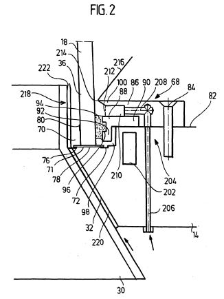
FIG. 2 shows a first embodiment of a bearing device according to the invention in a detail view of the region A according to FIG. 1; FIG.
[0061]
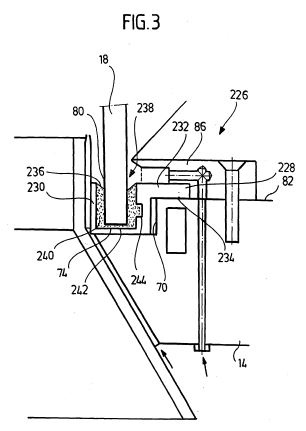
Fig. 3 is a detail view of a second embodiment of a storage device according to the invention and
[0062]
Fig. 4 is a detail view of a third embodiment of a storage device according to the invention.
[0063]
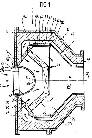
An embodiment of a radiation receiver according to the invention, which is designated in Fig. 1 as a whole with 10, comprises a pressure vessel 12 through which a working medium for receiving energy from solar radiation can be guided under pressure.
[0064]
The pressure vessel 12 comprises a pressure vessel wall as a front flange 14; the pressure vessel 12 is positioned so that the front flange 14 faces concentrated solar radiation 16. The solar radiation 16 is coupled via a mounted on the front flange 14 entrance window 18 in an interior 20 of the pressure vessel 12. The interior 20 is formed within the front flange 14 and of pressure vessel walls 22.
[0065]
The entrance window 18 is dome-shaped with an entrance window axis 24, with respect to which the entrance window 18 is rotationally symmetrical. The entrance window axis 24 is oriented perpendicular to the front flange 14, and preferably, the pressure vessel 12 and in particular the interior 20 of the pressure vessel 12 is rotationally symmetrical with respect to this axis 24 is formed. A vertex 26 of the entrance window 18 is facing the interior 20 behind an aperture 28 in the front flange 14th Solar radiation 16 passes through the aperture 28 to and through the entrance window 18, which is in particular a quartz glass window.
[0066]
In the aperture 28, an aperture insert 30 is inserted so that an end face 32 of the front flange 14 is covered. For this purpose, the aperture insert part 30 has a frustoconical ring element 32, wherein the (imaginary) cone tip is set back relative to the front flange 14 in the direction of the interior 20 of the pressure vessel 12. Furthermore, the aperture insert part 30 comprises an example cylindrical portion 34, which lies around a foot portion 36 of the entrance window 18 and is thus arranged behind the aperture 28. The aperture insert 30 serves to protect the front flange 14 from solar radiation. In particular, the aperture insert part 30 is designed as a secondary concentrator in order to concentrate radiation reflected at the aperture insert part 30 through the entrance window 18 into the interior 20 of the pressure vessel 12.
[0067]
The aperture insert 30 is not annular in cross-section in a variant of an embodiment, but has the shape of a polygon such as a achtzehnecks circumferentially.
[0068]
In the interior 20 of the pressure vessel 12, a designated as a whole with 38 absorber is arranged, which can be acted upon via the entrance window 18 by the solar radiation 16 and can be heated. By the absorber 38, the working medium for energy absorption is feasible, d. H. the working fluid heats up during the guide through the absorber 38. The absorber 38 is accordingly a volumetric absorber, i. H. the absorber absorbs the radiation substantially over its entire volume. For this purpose, the absorber 38 is made for example of a porous material or wire mesh. The radiation receiver is therefore a volumetric radiation receiver.
[0069]
The absorber 38 includes an inlet absorber 40 through which an inlet stream is led to preheat. For this purpose, an inner jacket 42 is disposed in the interior 20 of the pressure vessel 12, which is formed substantially parallel to the pressure vessel wall 22 and between the pressure vessel wall 22 and an inlet stream 44 is feasible. In the interior 20 of the pressure vessel 12, a flow space 46 is formed around the inlet window 18, through which the working fluid flows to an outlet absorber 50 after flowing through an inlet flow space 48 and flow through the inlet absorber 40. The flow space 46 is thereby formed between the inlet absorber 40, the inlet window 18 and the outlet absorber 50.
[0070]
The Auslaßabsorber 50 is arranged with respect to the entrance window 18 and formed so that a high radiation power is absorbed and a high volume flow through the outlet absorber 50 is feasible, so that the working fluid can absorb a high heat output.
[0071]
An outlet stream 52 is removed from the interior 20 after absorption of heat in the absorber 38.
[0072]
In the interior 20 of the pressure vessel 12, in the variant of an embodiment of a pressure vessel 12 according to the invention shown in FIG. 1, a further inner jacket 54 is arranged which has a wall 56 which is parallel spaced from a corresponding wall 58 of the inner jacket 42. Characterized a particular annular opening 60 is formed in the interior 20 of the pressure vessel 12 through which a partial stream 62 of the outlet stream 52 via a return space 64 in the inlet flow space 48 is traceable.
[0073]
By such a partial recirculation of an outlet flow from the Auslaßstromführung to an inlet flow in the inlet flow, a Durchgangsmassestrom the working medium flow can be increased so as to reduce in particular fluctuations in a mass flow distribution of a fluid flow in the absorber 38 and thereby possibly occurring temperature peaks, which can cause instability. Such a device and a corresponding method is described in DE 197 10 986 A1, which is hereby expressly incorporated by reference.
[0074]
Between the pressure vessel wall 22, the front flange 14 and the inlet flow space 48, a thermal inner insulation 66 is arranged, which comprises at least one layer of insulating material and in particular includes pressure compensation means for pressure equalization between the insulating material and a boiler interior, which are arranged over a large area relative to a layer surface of the insulating material. Such an insulation system is described in DE 197 13 598 A1, which is hereby incorporated by reference.
[0075]
In particular, it may be provided that the insulation system of the inner insulation 66 has a filter which is arranged between the pressure compensation means and a layer surface of the insulating material and serves to retain Dämmaterialpartikeln.
[0076]
The entrance window 18 is mounted on the front flange 14 by means of a bearing device. In a first embodiment of a bearing device according to the invention, which is designated as a whole by 68 in Fig. 2,the front flange 14 on its end face 32 has an annular recess 70 through which a support surface 72 is formed, on which the entrance window 18 with an end face 74 rests. Between the end face 74 while a seal 76 is arranged, which serves to seal the interior 20 of the pressure vessel 12 relative to the outer space. The seal 76 is in particular a multi-layer seal with layers of precompressed graphite and intermediate layers of thin stainless steel foils. The graphite serves to achieve a high temperature resistance and the intermediate layers to achieve a high mechanical strength.
[0077]
Between the seal 76 and the bearing surface 72 of the front flange 14, a sliding layer 78 is arranged, which has a reduced coefficient of sliding friction, so that the inner window 18 with the seal 76 on the sliding layer transversely to the entrance window axis 24 is movable and this movement takes place on the sliding layer 78 itself , In particular, the sliding friction coefficient for the sliding friction of the entrance window 18 with the seal 76 on the sliding layer 78 must be lower than the sliding friction coefficient for the sliding friction of the entrance window 18 on the seal 76 or for the sliding movement of sealing layers relative to each other. A typical value for the coefficient of sliding friction of quartz glass on graphite is 0.1. Preferably, then, the sliding friction coefficient of the sliding layer 78 is of the order of, for example,
0.05. It is then achieved that the relative movement of the entrance window 18 takes place with respect to the front flange 14 via sliding on the sliding layer 78, d. H. takes place at the location defined by the sliding layer 78.In particular, by the destruction of the seal 76 is avoided, for example by separation.
[0078]
By the movement of the entrance window 18 relative to the front flange 14, mechanical stresses in the entrance window 18 can be reduced, as they can arise in particular by the pressurization of the entrance window 18 and by the temperature of the inlet window 18 and the front flange 14.
[0079]
In a variant of one embodiment, the sliding layer 78 is formed by applying a lubricant to the support surface 72 in a defined area. As a lubricant, for example, high-viscosity silicone grease can be used. In addition to a good sealing effect, this material also has good temperature, pressure, weather and chemical resistance as well as a long service life under operational use conditions. In addition, high-viscosity silicone grease is free of alkali metals and alkaline earth metals. As a result, the risk of contamination of the entrance window 18 is avoided.
[0080]
It can also be provided a depot for the lubricant to get at Gleitmittelverlusten the lubricity of the sliding layer 78 by appropriate lubricant subsequent delivery (not shown in FIG. 2).
[0081]
In an alternative variant of an embodiment, the front flange 14 is provided at its bearing surface 72 with a corresponding low-friction coating to form the sliding layer 78, by which the sliding friction coefficient between the inlet window and the seal 76 with respect to sliding on the sliding layer 78 relative to the sliding friction coefficient between the inlet window 18 and Seal 76 with respect to sliding on the seal 76 is reduced.
[0082]
In order to be able to monitor a failure of the sliding layer 78, a tension measuring device 80 is arranged in the foot region 36, by means of which mechanical stresses in the inlet window 18 can be measured in this region, in order in particular to be able to indicate a failure of the sliding layer 78 as a defined sliding surface. In particular, the stress measuring device 80 includes one or more strain gauges. Such a strain gauge indicates strain and thus the presence of mechanical stresses in the region where the strain gauge is seated at the entrance window 18.
[0083]
At one of the interior 20 of the pressure vessel 12 facing inner wall 82 of the front flange 14 is seated in particular positively connected, for example by screw 84, a clamping ring 86th By this clamping ring 86, a retaining ring 88 is clamped to the front flange 14 in the interior 20 of the pressure vessel 12 is held. The retaining ring 88 serves as a holding element for the entrance window 18 and has a cross-sectionally L-shaped configuration, wherein a first wing 90 between the clamping ring 86 and the inner wall 82 of the front flange 14 is clamped and a second wing 92 in the recess 70 the Entrance window 18 is arranged facing.
[0084]
Between the entrance window 18 and the second wing 92 sits an adhesive layer 94 so that the entrance window 18 is fixed by this adhesive layer on the front flange 14. The adhesive material of the adhesive layer 94 is a highly elastic adhesive material, such as high-temperature silicone, so that the mobility of the entrance window 98 is retained on the sliding layer 78 in particular transversely to the entrance window axis 24 and also by the adhesive material of the adhesive layer 94 no significant forces on the entrance window 18 exercised.
[0085]
In the variant of an embodiment shown in Fig. 2, the retaining ring 88 has been glued before introduction of the entrance window 18 into the recess 70 in the manufacture of the radiation receiver 10 according to the invention so that when clamping the retaining ring 88, the adhesive layer 94 is slightly down in the direction of Support surface 72 is pressed. This results in a shear deformation in the adhesive layer 94, so that even without pressurization of the interior 20 of the pressure vessel 12, a contact pressure of the entrance window 18 acts on the support surface 72.
[0086]
Preferably, the adhesive layer 94 facing second wing 92 of the retaining ring 88 has an undercut 96, which is formed for example as an annular groove. This serves to increase the contact area between the adhesive layer 94 and the retaining ring 88. In addition, thereby a kind of positive connection between the adhesive layer 94 and the retaining ring 88 is made so that even with loss of adhesive contact between the adhesive layer 94 and the second wing 92 of the retaining ring 88, the entrance window 18 remains fixed to the front flange 14.
[0087]
In the recess 70, a cavity 98 is formed between the entrance window 18, the adhesive layer 94 and the retaining ring 88. To allow pressure equalization of the interior space 20 with this cavity 98, the adhesive layer 94 is circumferentially intermittent with respect to the entrance window axis 24 substantially parallel to that axis (not visible in FIG. 2).
[0088]
To protect the adhesive layer 94 from heat radiation from the interior 20 of the pressure vessel 12, a heat radiation protection device is provided. For example, this may be a highly reflective shielding element arranged on the surface of the adhesive layer 94 facing the interior 20 or a ceramic cord. In the embodiment shown in Fig. 2, the clamping ring 86 has a nose-shaped shield member 100, which extends so far to the entrance window 18 that still a pressure equalization between the interior 20 of the pressure vessel 12 and the adhesive layer 94 is made possible.
[0089]
According to the invention, a flushing device 204 is provided, by means of which the inlet window 18 faces the interior 20 of the pressure vessel 12 (pressurized side) and can be formed on the inlet window 18
to form a flushing film for cooling the entrance window 18. To go through the front flange 14 feed channels 206, which are continued in the clamping ring 86. In the clamping ring 86 corresponding transverse
channels 208 are then arranged, which open into a distribution space 210. At the distributor space 210 sits a grid 212 for swirling the rinsing agent at the exit from the distributor space 210. Through a gap 214 between the shield element 100 and the entrance window 18, the detergent reaches the interior 20. A surface 216 of the inner insulation 66 is arranged so that the entry of the detergent into the interior 20 of the pressure vessel 12 is not hindered.
[0090]
In an alternative embodiment (not shown in the drawing) supply channels for detergent in the cavity 98 and the detergent can pass through interruptions in the adhesive layer 94 in the interior 20 of the pressure vessel 12 pass.
[0091]
As rinsing agent in particular a steam-free purge gas is used. In particular, the purge gas is conducted over the adhesive layer 94 or through the adhesive layer 94 so that it is actively cooled.
[0092]
Furthermore, a flushing device 218 is provided for flushing a surface of the entrance window 18 facing the exterior. For this purpose, supply channels 220 are arranged between the aperture insert part 30 and the end face 32 of the front flange 14, which continue into a foot region 36 of the entry window 18. A feed channel 220 opens via a nozzle 222 in a space behind the aperture 28th For example, a supply channel 220 may be formed as an annular channel or circumferentially distributed tubes or tubes or the like may be provided. Via the flushing device 218, the inlet window 18 can be acted upon with rinsing agent in the space 224 (FIG. 1) which is open to the atmosphere, and in particular thermally particularly stressed areas of the inlet window can be specifically blown and thus cooled separately. It can be cleaned in this way, the entrance window 18 of impurities such as dust.
[0093]
Conveniently, it is provided that the front flange 14 is formed elastically deformable at least in the region of the support surface 72. In this way, unevenness of this support surface 72 can be compensated.
When not level bearing surface, the problem arises that in the entrance window 18 voltage spikes can be present. By ensuring an elastic deformability of the front flange 14, such voltage peaks can be reduced and thus the risk of breakage for the entrance window 18 can be reduced.
[0094]
It is particularly provided that the support surface 72 has a slight inclination in the radial direction transverse to the entrance window axis 24 in the pressureless state of the pressure vessel 12. When pressure load in the operating state with an appropriate design of such an inclined support surface 72 then this, when an elastic deformation occurs, again substantially perpendicular to the entrance window axis 24th
[0095]
In particular, it is provided that in the operating state of the radiation receiver 10, the deflection of the front flange 14 at the bearing surface is at least greater than 2. 10 <-4> the boiler diameter. For example, with an internal pressure of 15 bar and a bowl diameter of 1 m, the deflection should be more than 0.3 mm.
[0096]
The radiation receiver 10 according to the invention functions as follows:
[0097]
Highly concentrated solar radiation 16 is coupled via the entrance window 18 into the interior 20 of the pressure vessel 12 and heats the absorber 38 there. The working medium introduced via the flow space 46 heats up and passes through the inlet absorber 40, is thereby preheated and then passes through the outlet absorber 50 for the final heating. In the variant shown in FIG. 1, a partial flow 62 is branched off and returned by an outlet flow 52.
[0098]
By pressurizing the working medium, a window foot diameter of the entrance window 18 is reduced. Due to the heating, the front flange 14 expands. Furthermore, the front flange 14 warps under pressure and under heating, so that the parallelism between the end face 74 of the entrance window 18 and the support surface 72 is deteriorated. This creates mechanical stresses and in particular bending stresses in the entrance window 18 and in particular in the foot region 36 there.
[0099]
According to the invention, these stresses are at least partially degradable in that a movement of the entrance window 18 on the sliding layer 78 is made possible. In particular, the invention ensures that the entrance window 18 does not slide on the seal 76, but just on the defined location of the sliding layer 78th
[0100]
About the flushing device 204, the pressurized side of the inlet window 18 can be rinsed and cooled and the flushing device 280, the atmosphere-facing side of the entrance window 18 can be flushed and cooled. The adhesive layer 94 can be cooled via the coolant channel 202, which can also be cooled by means of the flushing device 204.
[0101]
A second embodiment of a bearing device according to the invention, which is designated in FIG. 3 as a whole by 226, is basically the same as described above. The same components therefore bear the same reference numerals. A retaining ring 228 as a holding element for the inlet window 18 is clamped on the inner wall 82 of the front flange 14 is held. The retaining ring 228 has an annular trough portion 230, on which radially outwardly with respect to the entrance window axis 24, a tab 232 is seated. By means of this tab 232, the retaining ring 228 between the clamping ring 86 and the inner wall 82 of the front flange 14 is clamped. For fluid-tight sealing, a seal 234, for example in the form of an O-ring, is arranged between the tab 232 and the inner wall 82.
[0102]
The trough portion 230 of the retaining ring 228 is positioned in the recess 70 of the front flange 14. The trough portion 230 itself has an annular groove 236 which serves to form a storage bed 238 for supporting the entrance window 18 in the retaining ring 228. For this purpose, a bearing bed material 240 is arranged in the groove 236 between the entrance window 18 and the retaining ring 228, which is deformable and in particular elastically deformable to allow movement of the entrance window 18 in the bearing bed 238 transverse to the entrance window axis 24 relative to the front flange 14. Further, bedding material 240 is disposed on a floor 242 of the channel 236 so that the entrance window 18 rests on bedding material 240.
[0103]
The bedding material is a material which has a high (compressive) modulus of elasticity parallel to the entrance window axis 24 and a low shear modulus transverse thereto. In particular, the bedding material 240 has an adhesive effect to provide additional adhesive fixation of the entrance window 18 to the retainer ring 228. To produce a positive connection between the bed material 240 and the trough portion 230 of this is provided with an example, circumferential undercut 244, can penetrate into the bed material.
[0104]
For example, high-temperature silicone 240 is used as the bearing bed material.
[0105]
In order to prevent the bedding material 240 from escaping and in particular extruding out of the channel 236, it may be provided that a cover, for example in the form of a ring, is arranged above the fill level of the bedding material 240 in the channel 236 (not shown in the figure). ,
[0106]
The elastic bearing bed material 240 assumes a holding function for the entrance window 18 in the retaining ring 228, d. H. fixes the entrance window, allows movements of the entrance window 18 in particular transversely to the entrance window axis 24 so as to be able to break down shear stresses in the entrance window 18, seals the interior 20 of the pressure vessel 12 from the outside and due to its elastic deformability is uneven at the bottom 242 and the end face 74 of the entrance window 18, so that voltage peaks in the entrance window 18, which may be caused by such bumps, are largely avoided or at least reduced and partially reduced. By the storage of the entrance window 18 in the storage bed 238, the tightness of the interior 20 with respect to the exterior space is ensured even in the unpressurized state of the pressure vessel 12.
[0107]
To protect against heat radiation from the interior 20 of the pressure vessel 12, as described in connection with FIG. 2, shielding elements for the bearing bed material 240 may be arranged.
[0108]
Incidentally, the bearing device 226 functions as the bearing device 68 described in connection with FIG. 2.
[0109]
In a third embodiment of a bearing device according to the invention, which is designated in FIG. 4 as a whole by 246, a distributor ring 248 is positively connected in the interior 20 of the pressure vessel 12 to the front flange 14. This distribution ring 248 is substantially the same structure as the clamping ring 86 according to the first and the second embodiment of a bearing device according to the invention and serves to distribute the detergent, but it does not act as a clamping device for a holding element.
[0110]
In the bearing device 246 according to the invention, a holding element 250 is provided for fixing the inlet window 18, which is connected to the front flange 14 outside the interior 20 of the pressure vessel 12.
In a variant of an embodiment, the holding element 250 comprises an annular portion 252, for example, which is arranged in the space 224. This section is followed by a widening annular portion 254, which is
adapted to the end face 32 of the front flange 14 and adjoins this. This section 240 is followed by an annular strap section 256, which rests against an outer wall 258 of the front flange 14 and which is connected to the front flange 14 in a form-fitting manner, for example by means of a screw connection 260. As a result, the holding element 250 is held on the front flange 14. It can be provided that the portion 254 is connected to the end face 32, for example by gluing or by a positive connection.
[0111]
The annular portions 252, 254 and 256 are formed, for example, by spaced tabs which are bendable. During assembly, the entrance window 18 can then be placed on the front flange 14, and for the final positioning and in particular fixation of the entrance window 18, the tabs of the sections 252, 254 and 256 are bent into their holding position.
[0112]
In the recess 70 of the front flange 14, the inlet window 18 is mounted on the seal 76 on a sliding layer 78, as has already been described in connection with the first embodiment of a storage device according to the invention shown in FIG.
[0113]
Between the retaining ring 228 and an outer surface 262 of the entrance window 18, which faces the outer space, sits an adhesive layer 264 for fixing the entrance window 18 to the support member 250th
The adhesive layer 264 thus sits in the outer space and not as in the storage device 68 in the interior 20 of the pressure vessel 12th This arrangement of the adhesive layer 264, the accessibility to this layer from the outside is possible and it is avoided that the adhesive layer 264 comes into contact with the working fluid, which is passed through the interior 20 of the pressure vessel 12. Also, the thermal stress of the adhesive layer 264 is reduced.
[0114
By a shield member 266 such as a ceramic cord, the adhesive layer 264 is shielded from heat radiation, so as to protect them from overheating.
[0115]
The retaining member 250 may also include a plurality of circumferentially spaced retaining plates. In a variant of one embodiment, the retaining element 250 is integrated into the aperture insert part 30.
[0116]
Otherwise, the bearing device 246 according to the invention functions as already described above in connection with the further embodiments of a bearing device according to the invention.