Parachute Airplane
http://blog.modernmechanix.com/2006/06/17/artillery-spotter-has-vertical-lift/
Popular Mechanix , February 1936
http://earlyaviators.com/edomenjo.htm
Popular Mechanix , February 1936
http://earlyaviators.com/edomenjo.htm
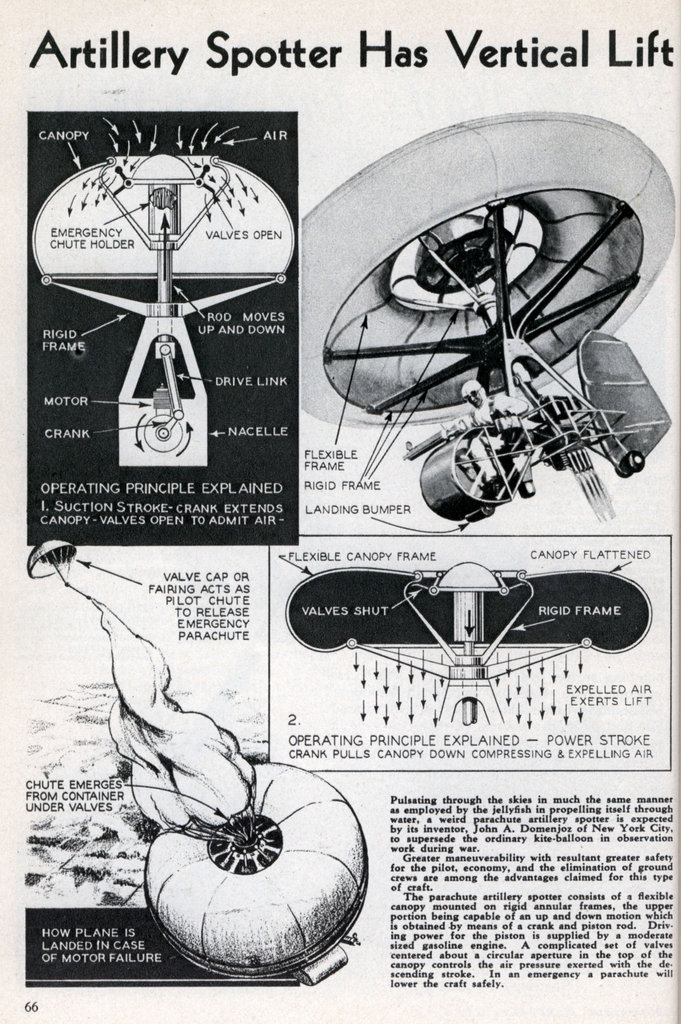
Pulsating through the
air in much the same manner as employed by the jellyfish in
propelling itself through water, a weird parachute artillery
spotter is expected by its inventor, John A. Domenjoz of New
York City, to supersede the ordinary kite-balloon in
observation work during war.
Greater maneuverability with resultant greater safety for the pilot, economy, and the elimination of ground crews are among the advantages claimed for this type of craft.
The parachute artillery spotter consists of a flexible canopy mounted on a rigid annular frame, the upper portion being capable of an up and down motion which is obtained by means of a crank and piston rod. Driving power for the piston is supplied by a moderate sixes gasoline engine. A complicated set of valves centered about a circular aperture in the top of the canopy controls the air pressure exerted with the descendig stroke. In an emergency a parachute will lower the craft safely.
US2000068
Aeronautical Machine
Aeronautical Machine
This
invention relates to aeronautical machines and in general is
a power actuated apparatus of a type to take the place of
the observation balloon for military use and consists of an
improved design adn arrangement, inexpensive in its initial
cost and in its operation and which possess many important
advantages over the customarily employed observation balloon
particularly as to maneuverability so as to materially
improve the safety factor for the pilot and the machine.
An important feature of the present invention consists of an improved motor driver means for obtaining the ascensional force comprising a flexible motive canopy, preferably of fabric and in the general form of a parachute, connected to be operated by a motor to operate in the nature of a flexible piston to produce power or lifting stroke as the result of suction above and pressure on the air beneath the motive canopy. The canopy is secured at its outer margin to a rigid frame or carrier for the motor and pilot and its central portion is connected to be vertically reciprocated by the motor and is provided with a one-way valve or shutter operative to close on the descending stroke of the canopy thus under the action of the motor to create an ascensional force governed by the speed of the motor. The pilot can thus readily control the elevation of the machine by varying the speed of the motor and additional means for vertical maneuvering is proivided in the form of a manually operated air valve to permit rapid change of elevation when desired while maintaining motor speed for prompt checking of the descent upon release of the valve.
Further important features include the provision of a supplemental, readily releasable, parachute to check the descent upon failure of the motor thereby with safety allowing the use of a motive canopy of lesser diameter than would otherwise be practicable.
The foregoing and other important features and advantages of the present invention will be more fully understood by reference to the accompanying drawing wherein like reference characters are applied to the corresponding parts in the several views.
In the drawings:


Fig. 1 is a view in central, vertical section showing my improved machine.
Fig. 2 is a similar view of the motive canopy and associated parts showing the position at the bottom of the power stroke.
Fig. 3 is a plan view of the central portion of the canopy and shutter arrangement.
Fig. 4 is a plan view of the carrier member or wherry.
Fig. 5 is a central, vertical sectional view showing a modified form employing a supplemental parachute carried by the central portion of the canopy.
Fig. 6 is a view in elevation showing the parachute in use and
Fig. 7 is a detail view in plan showing the central member of the canopy thereof.
In the approved construction embodying the features of my invention as shown in Figs. 1 to 4, a rigid carrier is shown comprised of a rectangular wherry 1 housing a driving motor m of the internal combustion type and having a compartment 2 for the pilot. The wherry is rigidly connected at each corner by means of posts or rods 4, with the annulus 5 formed to provide anchoring means for the outer margin of a flexible motive canopy 6, the central portion of which is connected to be vertically reciprocated by the motor m. To this end, the fly wheel 8 of the motor is provided with a crankpin 9 pivotally connected by pitman 10 to vertically movable rod 11 fitted within a vertical bearing or bracket 12 supported at the top of the wherry. The rod 11 is pivotally conected as shown to the tubular extension rod 14 which is pivotally connected at 15 to a central hub of a movable annulus 16; the hub portion as shown being connected by radial spokes 17 to the annulus. Accordingly, operation of the motor will transmit a vertical reciprocating motion to the movable annulus 16 to which the inner margin of the flexible canopy is attached so that the canopy is vertically reciprocated from its inner margin.
The movable annulus 16 is also formed with an upper hub portion 18 supported by radial spokes 19 defining segmental openings 20 adapted to be closed by segmental shutters 21 pivotally supported at 23 on the hub 18 in position to open upon swinging downwardly and inwardly and upon upward movement to close the openings 20 by engagement with the spokes 19 and under surface of the annulus. Each of the shutters is as shown provided with weighted rods 24 affixed upon its upper surface and inwardly curved to obtain a counter balanced and improved shutter action. The hub 18 is also formed as shown with central openings 26 closed by a spring pressed valve 27 to which a cable 28 is attached and carried downwardly within the rod 14 to a point accessible to the operator. The flexible motive canopy 6 is secured to the respective rigid annulus 5 and the movable annulus 16 by means of cables 30 and 31 about which its margins are wrapped and secured. At 32 there is provided a suitable slide bearing for the rod 14 supported upon spoke members 33, and 34 indicates tension connecting wires between the annulus and the wherry.
The flexible motive canopy 6 is formed of a suitable fabric such as rubberized canvas in circular dome contour and of such diameter as required to produce the desired ascensional force when its central portion is vertically reciprocated by the motor, it being understood that upon the upward stroke of the motor and annulus 16 the shutters 21 will open responsive to air pressure from above as shown in Fig. 1 wherein the parts are shown at the end of the up stroke and that upon the dowward stroke of the annulus 16 the shutters will automatically close so that upon the downward stroke a strong ascensional force is created as a result of suction above the motive canopy and air pressure beneath. Fig. 2 illustrates the position of the parts at the end of the power stroke.
As will be understood from the structure described the elevation of the machine may be readily controlled by the throttling of the motor and for more rapid descent the pilot may at will open the valve 27.
In Figs. 5 to 7, I have shown a desirable modified construction wherein for the purpose of added safety in the event of stoppage of the motor there is provided a supplemetnal parachute which may be manually released thus to supplement the parachute effect of the motive canopy and accordingly allow of the employment of the canopy of minimum dimensions with full parachute protection. As shown, the supplemental parachute is carried by the movable annulus 16 which is of modified form omitting the valve of the first described structure and having its upper hub portion provided with a cylindrical housing 40 for the supplemental parachute 41 folded in the usual manner with its outer margin connected by cords 42 to the housing at 43 while the inner marginal portion is folded over and into a central tube 44 and is connected to an ejector member 45 of tubular form slidably fitted at its bottom portion within a cylinder 47 secured to the lower hub 15 of the annulus. Beneath the ejector 45 there is positioned a compression spring 48 and the ejector member is held in position against the influence of the spring by a latch 49 from which an operating cable 50 is extended downwardly and accessible to the pilot. The ejector member has pivotally secured thereto at its upper portion at 52 an umbrella-like pilor parachute 53 to assit the full ejection of the parachute 41. The top of the housing 40 is normally closed by pivoted flaps 54 pivoted at 55. The movable annulus as shown is further modified by the arrangement of a double series of air valve sutters 56-57 pivoted at 58-59 upon the annulus member. In emergency as will be understood the operator releases the hatch 49 allowing the spring to upwardly eject the parachute 41 with the pilot parachute assisting as shown in Fig. 6.
My improved machine, as will readily be appreciated, is particularly adapted for military observation with materially increased safety to the pilot as compared to the free balloon and further is advantageous by reason of compactness and portability, is economical as compared to the gas balloon. Its motive canopy is at all times available as a parachute for safety and with the manually controlled valve is active as a balanced parachute for improved control in maneuvering of the machine. As will be unerstood varied modification may be made in my improved machine without departing from the invention as defined in the appended claims... [ Not included here ]