Horace C. DUDLEY
Electric Field Rocket
Analog Science Fact and Fiction (November 1960, p. 83-94)
"The Electric Field Rocket"
by Horace C. Dudley
During a lecture on nuclear theory, the professor explained the disintegration of uranium. At the end of the lecture, he stated, “This system of mathematical theory shows a definite probability that an airplane may pass through a rocky cliff and come out the other side unscathed”.
It was here that the writer parted company with “modern” nuclear theory. My flying days began when I ran away from home about 1921 to sneak my first ride in a Jenny. Since then having experienced one air crash, and witnessed many others, no amount of calculations can convince me that which is impossible, can be possible. Out of this came a critical examination of all mathematical theory, which led to some theorizing on my own (1).
The state of our theorizing has been well summed up (1953) by a Nobel prize winner, Louis de Broglie: “The history of science shows that the progress of science has constantly been hampered… by principles that we have come to assume without discussion”. Prof. J. C. Bailar, President of the American Chemical Society pointedly reminded scientists (1959) that the theories of today have superseded those of yesterday, and that they in turn will be superseded by those of tomorrow, even if today’s seem perfectly logical.
As a starting point it is suggested that one examine several of the references which discuss atmospheric electricity (2, 3, 4). It will be found that the old concept of current flow (+) to (-) is often renamed in these writings. Here then is the indication tat our present concepts of charge, field, and current flow are in a chaotic state. If our electron and x-ray tubes function by reason of electron passage, then current flow must be electron flow, (-) to (+). And there is current flow, ionosphere to earth!
Theoretical studies of charge, fields and gravity led to the prediction that the earth is a (+) charged “particle” spinning in a hue (-) charged field (1). But theorizing is one thing and experimentation is still another. So a series of privately financed experiments were begun, utilizing both laboratory apparatus, and small rocket. The procedures and results are outlined below.
Laboratory Experiments
In October 1957, preliminary experiments were begun with a small Van de Graff generator producing a maximum electrostatic (+) charge of about 75,000 volts. This unit was used to study the action of various one-quarter to one-half inch spheres and various powders under the influence of a (+) charged field.
These preliminary tests indicated that a large electrostatic generator would be useful. After several modifications, the final unit constructed was a van de Graff generator having a spherical collector head 12 inches in diameter, capable of producing a (+) charge of 425,000 volts. The capacity of he ES generator was increased by employing an electronic high-voltage generator, and applying a (+) potential of 25,000 volts on the groundside brush of the Van de Graff.
These units were used to study the movement of (+) charged one- to four-inch diameter hollow spheres in various (+) and (-) charged electric fields. The spheres were made of glass, plastic, or aluminum. The inner and/or outer surface of the non-conductors were rendered conducting by spraying with lacquer containing aluminum powder. In the case of glass spheres, one of the best sources of supply was ordinary Christmas tree ornaments which contain inside a flashing of metallic silver. This can easily be removed with a few drops of nitric acid. A non-conducting body does not take a charge and therefore is not repelled.
A sphere placed on top of the collector of the Van de Graff generator may take on the same charge, in this case 425 KV (+) with respect to ground. This charging of the small sphere will take place only if one surface is conducting. In the case of nonconductors, if the inner surface only is rendered conducting and is connected in some way with the collector head, then the charge is distributed over the inner conducting surface and the sphere is repulsed. In effect the charge “radiates” as if a point source at the center of the hollow sphere.
Since the charges on the collector and the sphere are both (+), when the electrostatic repulsion of (+) charge for (+) charge is greater than the attraction of gravity for the sphere, then the sphere will move vertically t a point where the electrostatic force equals gravitational force:
Fe = k q1 q2 / d2
Where Fe =
electrostatic force,
D = distance between charges,
q1
= charge on collector, a constant under the condition of the
experiment,
q2
= charge on sphere, a variable dependent on various factors,
k = a dielectric factor, a constant, but only under a definite
set of conditions, i.e., barometric pressure, temperature and
humidity.
When the sphere rises from the collector, the electrostatic force of repulsion (Fe) is greater than the attraction of gravity (g); Fe > Fg. As the sphere rises, a point is reached where Fe = Fg. The conditions of this equilibrium are determined by the following factors (assuming q constant):
(a) Surface-area mass ratio of sphere;
(b) Rate of loss of charge (q) of sphere by reason of leakage, a rate influenced by the value of k, which depends on barometric pressure, temperature, humidity, and surface imperfections;
(c) Increase (q) by reason of the acceleration of the sphere as it begins its rise.
The results of many preliminary series of experiments established the above conditions. In later more extended experiments it was found that the mass of material above the generator, the electrical conductivity of this material, the time of day and season of the year all influenced the height of rise of the sphere above collector head.
These results show that by careful control of all conditions, it is possible to “titrate” the attraction of the (-) zone above the earth for the (+) charged sphere as it is repelled by the (+) charged collector head.
These findings resulted from more than two years of experiments. To those who may wish to check or extend these findings, it is recommended that the experiments be carried on in an isolated lightly constructed building in which temperature and humidity can be rigidly controlled. Only the use of a high-speed movie camera to record height of rise of the spheres will provide refined data and permit accurate plots.
For an explanation of the influence of season of the year and time of day on the (-) charge above the earth see discussion of rocket experiments which follow.
Rocket Experiments
As a result of the laboratory experiments outlined above, it was postulated tat a rocket may become a (+) charged body, repelled by the (+) charge of the earth and simultaneously attracted by the (-) charged zone above. This reduced to its simplest, is a macro reduction of R.A. Millikan’s oil drop experiment (1909), in which he, at will, augmented or counterbalanced the force of gravity on charged oil droplets, by means of electrostatically charged plates. For this Millikan received the Nobel prize for determining the nature of the unit charge on the electron.
What is given here is the outline of results of 200 firings of small rockets, and details of a series of do-it-yourself experiments utilizing readily available and safe materials in order that others may repeat the experiments, and, it is hoped, confirm and extend the findings.
Rocket Construction
A --- Obtain at least three Aerobee-Hi rockets or others of similar design, which utilize Rock-A Chute motor. Assemble in the usual manner, but eliminating the parachute. Install a hard plastic guide tube in place of the paper straw as supplied (1/4” OD, 3/16” ID, 4” long, with 45 degree bevel at each end). Spray all parts and surfaces, inside and out, with a clear acrylic lacquer. Repeat spraying three times, allowing suitable drying time between coats. Allow to dry finally overnight in a warm room. One of these rockets is now sprayed only inside the rocket body with aluminum paint, or lacquer. Another rocket is sprayed so as to cover all surfaces, inside and out, with aluminum paint o lacquer. Beneath outer coating is now an electrically conducting surface. The third rocket is retained as a non-conducting body, completely impregnated with acrylic lacquer.
B --- Secure at least three die-cast high dielectric plastic Alpha-I rocket bodies, complete with rubber nose tip. Cement the tip to the body, To each, cement a hard plastic guide tube midway between two fins (1/4" OD, 3/16" ID, 4" long). Pour a bit of aluminum paint or lacquer inside the body of one rocket. Rotate, drain and allow to dry. Spray all surfaces of the second Alpha-I, inside and out with the aluminum paint, allow to dry thoroughly. Retain the third rocket clean, with no coating.
C --- The rocket motors utilized in all these tests are the standard Rock-A-Chute products, type A4 or B6, which are used as issued in the Aerobee-Hi models. For the Alpha-I, obtain garden hose washers, which are fitted and cemented around the base of the Rock-A-Chute motor, flush with the orifice end of the paper case. This rubber washer serves as a thrust collar and retaining ring. The size of standard hose washers causes the fit of the rocket motor to the Alpha-I to be surprisingly snug and shipshape. A bit of tape or paper wrapped around the motor helps to retain the motor in the body.
Firing Conditions
In warm, pleasant weather the amount of moisture, as grams cubic meter, is about eight times that found under cold, dry winter conditions. The optimum conditions for the study of the effect of the earth’s electric field on the height of rise of rockets are winter conditions, some distance from any large body of water and low humidity.
Under warm, humid conditions, all rockets become conducting bodies because of absorption of moisture on the surface of any substance. To check this, heat a pyrex beaker in an oven to 125 C. Cool in a dessicator. Rapidly bring to equilibrium on an analytical balance. Watch the progressive increase in weight. This is the water vapor being absorbed on the surface of the glass.
Those fortunate to live in a semi-arid or desert region, have a definite advantage in conducting tests of this kind, since the crux of the whole problem is electrical conductivity of the air and the rocket’s surface. High altitudes, dry, cold conditions are those which favor the tests, since these are conditions of lowest conductivity.
Firing Schedule
Fix the Aerobee-Hi rocket launching rod so that it is vertical and is in contact with the ground. In case of dry sand, concrete, or arid conditions, dig a hole near the launching site, drive a metal rod into the ground and electrically connect this ground pin to the launching rod. This insures that the rocket is at ground potential for the full length of the rod. Select an open area at least 300 yards away from habitation or roadway. Keep bystanders to a minimum (you will see why later).
The best time to obtain the greatest potential gradient as volts/meter near the surface of the earth is 8-11 AM and 5-7 pm in winter. In summer the most advantageous times are 809 am and 8-9 pm. The best season of the year is November through February. Thus the optimum time of firing to reduce to a minimum the leakage of the earth’s (+) charge of the rocket is precisely the time at which the attraction of the (-) field is greatest. Thus to study these phenomena seriously it necessary to endure soe discomfort. Select a clear day, December through January with low temperature and low humidity and fire between 8-11 AM (See refs 2 and 4 for details of earth’s potential).
(1) Fire the lacquer impregnated non-conducting Aerobee-Hi wind. Repeat using the untreated plastic Alpha-I. Again be wary as the aerodynamic stability depends in part on conductivity. These two rockets represent uncharged bodies being propelled only by rocket power.
(2) Fire the Aerobee-Hi rocket which has only a conducting inner surface. Note stability of flight, height of rise, effect of cross wind. Fire the Alpha-I which has only its inner surface rendered conducting.
(3) Fire the Aerobee-Hi and Alpha-I rockets which have all surfaces coated with the conducting lacquer. Note height of rise, trajectory and effect s of cross wind. Those rockets have initially the same (+) charge as the earth.
In order to get a good approximation of the heights of rise, station two observers at about 300 feet from the launching site, positioned such that they are at right angles to each other, with respect to the site. One should be facing directly away from the sun, i.e., between sun and site.
Accurately measure each leg of your triangulation grid, and the distance from observer to observer. A very useful sighing quadrant may be prepared by nailing with one nail a lathe, slat or yardstick to a corner of a square board, about 12 x 12 x 1 inch. Using a small protractor, lay off the angles from 0 to 90 degrees with the 0 degree at the bottom edge of the sighting board. Always hold this board perpendicular to the ground, and with the 0 degree line parallel to the ground.
We are now ready to measure the angle of rise by sighting along the top edge of the pivoted slat:

If B = 300 ft
And Angle A --- Then height (h)
is --- Tangent --- is
37 --- 0.754 --- 226
ft
50 --- 1.19 --- 357 ft
75 --- 3.73 --- 1119 ft.
If one selects convenient and permanent base lines for the above, and calculating tangent values vs height, it is easy to prepare a table so as to read off directly the heights at the launching site, rather than wait to work up your results. The necessary tangent values can be found in any geometry text and scientific handbooks.
Under optimum conditions of time, temperature and humidity, the conducting rockets will attain altitudes about 400% greater than non-conducting rockets.
Should the rocket veer too far off the vertical path, it is easier to calculate it height when you have two observers. If you estimate the distance fro one observer to a point directly under the highest part of the trajectory, then using this value, and the observed angle, calculate the height by the Tangent method outlined above.
From 200 firings carried out by the author, the following general facts emerge.
(a) Both high humidity and high temperatures decrease the rise of a rocket so constructed as to be an accelerating, charged body.
(b) Conversely, low temperature and low humidity greatly favor the rise of a rocket so constructed as to retain its charge during acceleration.
(c) A completely non-conducting rocket shows erratic flight characteristics in cold, dry weather.
(d) An accelerating, conducting rocket becomes a moving charge in an electric field and thus establishes concentric magnetic lines of force. These lines of force couple with the magnetic flux of the earth, stabilizing the flight of the rocket. This effect causes the rocket to resist changes in its vertical path, such as the force of crosswinds might induce.
(e) Under optimum conditions the electrostatic field of the earth may be utilized to aid the thrust of a rocket motor.
Conclusion
About 1750, Benjamin Franklin proposed the theory of a single electric “fluid”. He rubbed a glass rod with silk and guessed that some of the fluid was transferred to the glass. Therefore, he called the charge on the glass positive (+). When he rubbed a hard rubber rod with wool, some of the fluid seemed rubbed off the rubber, and the charge was labeled negative (-). Since the charges were different, the fluid flowed from glass positive to rubber negative. This is the origin of the direction of flow of electric current which appeared in practically all textbooks until about 1940.
But with the development of the Bohr concept of the atom, and the clear evidence of the particulate nature of electricity, derived from electronics, the old terminology began to change, showing the flow of current, negative to positive. But in this good year of 1960, what is available in our textbooks and reference libraries, indicating the state of our concepts regarding the flow of electric current?
Encyclopedia Americana, Ency. Britannica, World Book Encyclopedia, Scientific American, etc…
And so we may find whatever may suit our fancy. In fact, many widely used physics texts, while explaining current flow as electron flow, neg to pos, still retain the diagrams of earlier editions showing the flow, pos to neg.
Science is in one of those transition periods where new knowledge conflicts with old terminology and there is just now a woeful lack of critical evaluation of what one scientist means by his writings and diagrams. Older references are cited and concepts which cannot stand up in the light of new data. In short, we have come so far so fast that our further progress is being hampered by outmoded concepts retained, references and still taught as valid. Faulty communications lose battles!
In the Spring of 1958, as the result of laboratory studies with various charged spheres. A prediction --- call it an educated guess --- was hazarded: The Russians are firing their rockets from a high, dry, cold place. Subsequently published reports showed their major launching site to be northeast of the Caspian Sea (45 N) on a desert plateau, altitude about 500 feet. They fire their high thrust rockets largely during cold weather, after October 1. These are the conditions which the rocket firings reported herein show to be optimum for taking advantage of the earth’s electric field. Atmospheric conditions which exist at Cape Canaveral and Point Mugu are those which completely negate this effect.
References
(1) H.C. Dudley: New Principles in Quantum Mechanics; Exposition Press, NY, 1959.
(2) Encyclopedia Britannica, Vol. 8 (1947); “Atmospheric Electricity”
(3) J.A. Chalmers: Atmospheric Electricity; Pergamon Press, 1957.
Analog Science Fact and Fiction (1961 ?; p. 83-96)
"Report on the Electric Field Rocket"
by Harry Stine
When Dr H.C. Dudley’s article on the Electric Field Rocket appeared in these pages in the November 1960 issue, his investigations aroused a great deal of interest among the model rocketeers of the National Association of Rocketry. There was only one way to settle the question once and for all: perform Dudley’s experiment with model rockets. If Dudley were right, the experiment would be a true predictable one and would duplicate his findings. This is in the finest tradition of science. No amount of discussion will settle the question; it must be settled by checking the theory with experiment. The results must then be published.
The NAR was in a unique position to carry out the model rocketry experiments of Dudley. Since 1957, the NAR has developed in-flight optical tracking systems for model rockets that have reasonable accuracy. Model rocket engine manufacturers can supply propulsion systems of very close tolerance. Many NAR members are expert model makers capable of building very fine rockets.
The Peak City Section of the NAR in Colorado Springs, CO was perfectly situated to carry out the tests. Their rocket range is the most extensive and well-equipped in the country, consisting of 40 acres of flat prairie at an elevation of 6380 feet. There are clear skies most of the year, and the climate meets the Dudley specifications beautifully --- high altitude, clear skies, low humidity.
Supervised by Bill Roe, five teenage model racketeers undertook the task of running the tests. None of these people had any contact with Dr Dudley; they know him only from his Analog article. They used his article for instructions for building their models, following his directions exactly.
Four different series of models were used. The design of the models varied from series to series, but the five rockets in each series were constructed as nearly alike as possible, with the exception of the presence or absence of the conductive layer.
In each series, the five models differed as follows:
Model 1: A control model. A standard model rocket built of paper and balsa wood with a clear layer of Krylon sprayed inside and out. This Model was the standard against which the performance of the others in the series would be compared.
Model 2: Identical to Model 1 except with a layer of Krylon aluminum paint sprayed on the inside of the model over a clear Krylon spray base. The exterior of Model 2 was a spray coat of clear Krylon.
Model 3: Identical to Model 1 except with a coat of Krylon aluminum paint sprayed over both the inside and the outside of the model over a coat of clear Krylon.
Model 4: Identical to Model 1 except with a layer of aluminum foil on the inside of the model over a clear Krylon base. Exterior was sprayed with clear Krylon.
Model 5: Identical
to Model 1 except with a layer of aluminum foil on both the
inside and outside of the model over a spray coat of clear
Krylon.
The reason for using Models 4 and 5 was to insure a true
electrically conductive layer by means of the foil. Peak City
Section rolls its own paper tubes for model rocket bodies, and
was, therefore, able to roll special tubes with inside and/or
outside foil layers. This was an admitted departure from the
Dudley instructions designed to double-check the premises.
The model rocket engines used in the tests were NAR type A.8-4 and B.8-4. The NAR has developed a method of classifying commercial rocket engines by total impulse --- thrust multiplied by duration --- and has created a coding system for describing the performance of such engines. The first letter indicates the total impulse range, the first number indicates the thrust in pounds with fractional pounds expressed as decimals, and the dash number indicates the number of seconds (to the nearest second) of time delay built into the engine.
All of the engines used were commercially made by a model rocket engine manufacturer by means of a fully automatic machine. The engines used in the tests were selected from the same production lot. One from each batch of 100 engines had been static tested on a recording-type test stand. The accompanying thrust-time curve was obtained from the sample engines of the production batch used. Tolerance on these engines is very close…
In flight, the models were all tracked by means of optical theodolites constructed by the boys. They consist of surplus 8-power elbow telescopes with reticles and cross hairs. They are attached to alt-azimuth mountings with elevation and azimuth dials. Mounted person manning the theodolite is on sturdy tripods, they are accurate to at least 1/2 degree. During flight operations, the connected to the firing point by a telephone so that he hears the countdown and can read back his azimuth and elevation angles. He tracks the model from the instant of take-off to peak altitude, where he ceases tracking and locks his tracking mount.
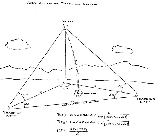
The standard NAR tracking system was used for the tests. It consists of two tracking stations on a measured baseline. If you will look at the tracking system geometry in the accompanying drawing, you will see that it does not matter where the tracking stations are with respect to the launch area, or where the model is in the air with respect to the ground. If the baseline between the stations is known, and if the tracking angles from each station are known, it is possible to determine by triangulation exactly how high the model is. Moored balloon calibrations of this system have shown it to be accurate to 2% for altitudes up to 1000 feet. If you want better accuracy or are flying higher than this, use a longer baseline.
A three-station system is admittedly more accurate, but the data reduction gets messy and cannot easily be handled in the field with trig tables and a slipstick.
The tracking angles from each station are reported in to the launch area where they are copied down. Simple trig reduces these angles to altitude data.
The tests of series One took place on October 29, 1960. High winds made things difficult until January 7, 1961, when the remaining three series were flown.
Special flight sheets were used for the electric field rocket tests, and one of these is reproduced with this article. All possible data was recorded for each flight --- time, temperature, humidity, winds, barometer, sky, model type, launch weight, motor type, conductive layer used, and general flight characteristics. The PC Section hoped to be able to measure the atmospheric charge in volts/cm as well, but they were unable to complete the equipment in time for the flight tests.
In all, 20 flights were made. 19 of these were tracked, and track was lost on one flight.
A summary of the flight test data, as compiled on the accompanying table, shows some interesting things that should settle the electric-field rocket question. The results are probably best summed up in Bill Roe’s comment, “I have been unable to detect any difference in the flight of the rockets. They were built as closely as possible to the Dudley specs.I suggest Captain Dudley be invited to bring his rockets to the range and try them”.
The NAR has drawn the following conclusion of the Dudley Electric-Field Rocket:
(1) There is very little apparent difference in the achieved altitude or light characteristics of model rockets when provided with an electrically-conductive surface.
(2) Model rockets with and without conductive coatings flown on separate days with different weather factors show very little difference in performance.
(3) The altitude spread of the results is that normally experienced with ordinary models of identical construction, probably due to small difference in engine performance, minute differences in models, variations in launching conditions, and tracking system errors.
The testing crew decided to discontinue the project after 20 flights because it seemed to them that there was nothing to be gained by further flying. The test flights told them that they weren’t getting the claimed altitude increase or the claimed stability performance.
This essentially concludes the serious reporting aspects of these tests, but leads us to some interesting speculation regarding what might have caused Dr Dudley to draw his conclusions. I repeat that this is strictly speculation. The NAR did no get the expected results. Why? What did we do wrong, or what did Dr Dudley, in all scientific honesty, interpret incorrectly? None of us feel that we are competent to judge his overall theoretical work on the basis of the NAR tests; perhaps other tests in other areas may confirm all or part of it; perhaps it will have to be modified or even discarded. But that is up to the physicists; we are scientists on a busman’s holiday, amateur scientists, and model racketeers. Primarily, for this report and these tests, model rocketeers.
Dr Dudley’s photos showing the acceleration of his models at take-off mean nothing to us. Single photos can’t. If the camera shutter had been tripped electronically by a microswitch at the precise instant of launch, they would be interesting. But I can get and have gotten photos of takeoffs which, if I laid them side by side, might indicate that one model had greater acceleration than the other. But there would be no way of knowing unless I had tripped the shutter at precisely the same instant of launch in each case.
A single-station tracking system can give very erroneous altitude reading, as we discovered in 1957. The NAR initially used a single station system, began to question its accuracy, and went to a dual station system. I recall one particular design that consistently turned in 1,500 foot peak altitudes with the single-station system, but which began to give 500 foot altitudes once the two-station system was put into use.
A model rocket simply does not go straight up over the launcher every time. It may veer several degrees either side of vertical on the way up. In doing so, it may approach the tracking station or fly away from it. In the first instance, the peak altitude appears to be higher; in the second case, lower. Model rockets all have a tendency to weathercock into the wind slightly because o the fact that they are fin-stabilized vehicles possessing arrow stability.
If the tracking station is one three hundred feet away and, if it happens to be up-wind of the launcher on the day of the flights, the vehicles will appear to go higher.
However, this does not answer the question of the higher altitudes that Dr Dudley claimed for his coated models. We must look further into the problem. What happens if we compute the altitude of the NAR test models using the one-station system?
The data from Flight #8 shows us what can be expected. The NAR tracking stations were 1,000 feet from the launch pad. Using this as the baseline, and using the 40 degree elevation angle recorded from one station for that flight, we compute an altitude of 839 feet. However, using two stations, this comes down to a reduced altitude of 635 feet.
This is still not enough to account for the altitude increases reported by Dr Dudley.
At this time, we’ve checked everything we can think of with the thought that perhaps we did something wrong. The models were properly built according to the instructions given by Dr Dudley. The launchers were grounded by wire to a steel fence post driven more than two feet into the ground. The weather was clear, cold and dry, and the tests were made at high altitude.
Instead of concluding an argument, we may have started a new one. Who is right? When an amateur scientist does not confirm the results of another amateur scientist, who is going to be believed? The professional people will probably pay no attention , or they would have run some tests themselves in the first palce.
Since the NAR boys followed the instructions exactly, they certainly believe they are right. The essence of the question is the predictable experiment done from a cook book. Mystics use no cook books. Mysticism is based on faith. Did Dr Dudley neglect to mention some important point of procedure in his article? If so, it was not proper scientific reporting.
Another interesting speculation raises its head: If the Electric Field Rocket Effect is real, why hasn’t it been noticed before? Certainly with all the experiments and flight tests made with rockets, some factor should have shown up. Not all rocket flights are made from damp, sea-level locations. I recall standing on a desert hummock in freezing temperatures during winter flight tests from White Sands at an elevation of nearly 4,000 feet. No unexplained factors turned up at White Sands during the time I was there. And, good friends, a metal rocket resting on a steel launching table bolted to a concrete slab is most certainly at ground potential!
And, perhaps the wrong question has been asked! Maybe the electric field rockets work best at low altitudes. If so, we will be finding this out about the time you are reading this, duplicating the experiment again on Long Island, NY in dry fall weather. If the eastern NAR groups confirm the Dudley experiments, you will most certainly hear about it.
In any event, it was time to make a report. To date, members of the NAR have not confirmed the results of Dr Dudley’s rocket tests. We invite you to come to your own conclusions.


US3,095,167
Apparatus for the Promotion and Control of Vehicular
Flight


