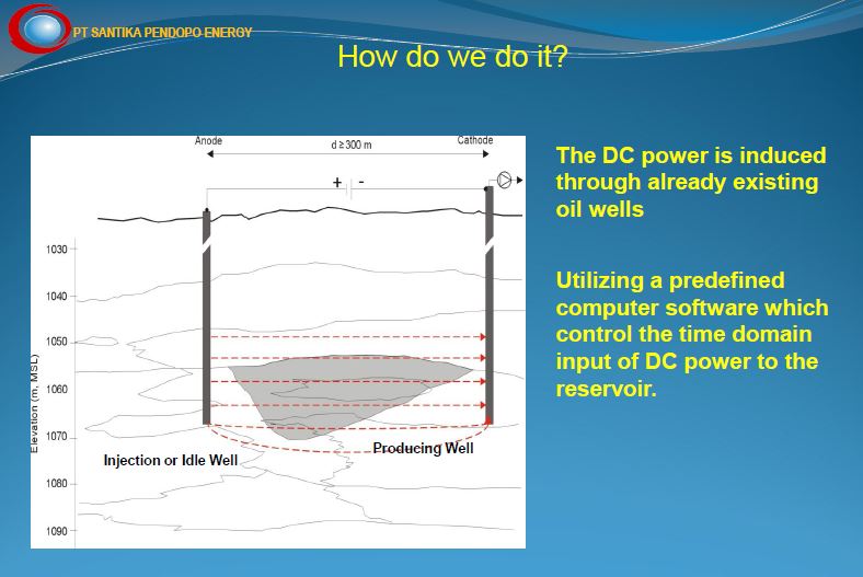
Electro-Osmosis of Oil
Electrical Stimulation of Oil Recovery
It has become unarguably obvious to all but the most recidivist technocrats ( present company excepted, of course ), that "fracking" for natural gas is unprofitable, unsustainable, unclean, and it is a direct cause of earthquakes. But what else can we corporatists vampires do ?
In anticipation your mindful inquiry, here is a sneak peek at the Next Bigly Thing in Petro-Pumping : Electro-Osmosis !
Water in porous material ( e.g., soil or concrete ) is attracted to ground, to the negative electrode. This factoid is used industrially to dewater concrete constructions at a much faster rate.
The same principle applies to oil. Not only is the migration of molecules accelerated, but the overall energy requirements are reduced.
Electrical field treatment of oil in pipelines also minimizes surface tension between the pipe and petroleum, thereby accelerating delivery.
In this same manner, apparently exhausted wells can be rejuvenated in a timely manner, simply by electrically inducing the planet to excrete still more black goo for our Needful Things.
Considerable field research has been performed over several decades to determine the parameters for electro-osmotic production of oil. The required voltage, amperage, waveforms, and frequencies are known, and equipment has been developed to implement the technology.
Contents
Electropetroleum.com : A Vast Opportunity — Billions of Barrels Waiting Below Us
Wittle, et al. : Direct Electric Current Oil Recovery (EEOR) — A New Approach to Enhancing Oil Production
Haroun : Optimizing Electroosmotic Flow Potential for Electrically Enhanced Oil Recovery (EEORTM)...
Laursen : Electro-osmosis in oil recovery : Progress report II
Al-Hamaiedh, et al. : Treatment of oil polluted soil using electrochemical method
Oilrec Trechnologies
Sumatra Field Trial
US7325604 : Method for enhancing oil production using electricity
WO0303823 : Electrochemical process for effecting redox-enhanced oil recovery
US3915819 : Electrolytic oil purifying method
US2013277046 : Method for Enhanced Oil Recovery from Carbonate Reservoirs
US7325604 : Method for enhancing oil production using electricity
US2005161217 : Method and system for producing methane gas from methane hydrate formations
US2799641 : Electrolytically promoting the flow of oil from a well
US3417823 : Well treating process using electroosmosis
US3724543 : Electro-thermal process for production of off shore oil through on shore walls
US2014116683 : Method for Increasing Bottom-Hole Formation Zone Permeability
RU2132757 : Method of Removing Hydrocarbons from Soil
KR20010086551 : Purification Method of Contaminated Soil with Petroleum Oil
RU2602615 : Method of Soil Cleaning from Hydrocarbons
KR101464878 : Remediation System for Multi-Contaminated Soils
US4645004 : Electro-Osmotic Production of Hydrocarbons Utilizing Conduction heating of Hydrcarbon Formations
WO2012158145 : Method for Electrokinetic Prevention of Scale Deposition in Oil Producing Well Bores
http://electropetroleum.com/technology/
A Vast Opportunity — Billions of Barrels Waiting
Below Us
Given today’s fluctuating oil prices, as well as the ever-present politics of supply and demand, the need for further heavy oil recovery is enormous… as is the opportunity. Currently, there are several hundred billion barrels of known heavy oil reserves in North America and vast reserves elsewhere in the world. The prevailing methods for heavy oil extraction are steam-based (which require massive amounts of water and power), including steam flood, cyclic steam injection, and steam-assisted gravity drainage. However, Electro-Petroleum, Inc. (EPI) now offers a cost-effective alternative and can recover oil in reservoirs where steam methods cannot… and with less effect on the environment.
EEOR – Electrically Enhanced Oil Recovery SM — Highly Effective for Heavy Oil Recovery, Cost Savings, and the Environment
This patented technology from Electro-Petroleum, Inc. (EPI) sets a new standard for heavy oil recovery that requires no water and less power to apply. The process enables low-cost recovery of stranded oil reserves by applying electric currents to hydrocarbons in the ground, which upgrades and mobilizes heavy oils that are too viscous to be extracted by conventional pumping techniques. Plus, EEOR is dramatically more environmentally friendly than alternative heavy oil extraction techniques (such as steam injection), which requires massive amounts of water and power.
Breakthrough technology for heavy oil recovery using direct current electricity.
Demonstrated ten-fold increase in production in field tests.
More cost-effective and less capital intensive than other secondary recovery processes.
Ability to access oil heavy oil reserves where other technologies cannot… without depth limitations.
Our Technology
EEOR – Electrically Enhanced Oil Recovery SM process involves passing direct current (DC) electricity between cathodes (negative electrodes) in the producing well and anodes (positive electrodes) either at the surface or at depth.
Important facts include:
EEOR has demonstrated, in an 18-month field test, the ability to increase heavy oil production ten-fold from baseline levels in a field where other secondary oil recovery techniques were not successful.
Able to retrofit exiting wells for EEOR
EEOR is able to be effective in reservoirs where steaming is either ineffective or uneconomical
Energy costs for EEOR are less than $4/barrel, and capital costs are a fraction of steam-based methods.
The 3 Mechanisms of EEOR in Heavy Oil Recovery:
Electro-Chemical Upgrading, or “Cold Cracking” — Oxidation and reduction reactions break down heavy oil molecules into lighter oil molecules, upgrading the oil in the reservoir.
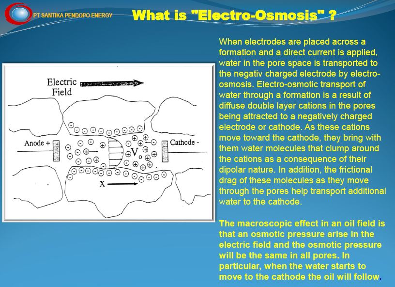
Electro-Kinetics or Electro-Osmosis — Oil in the reservoir migrates toward the negative cathode, creating a drive mechanism, or flow, towards the well.
Resistance, or Joule Heating — Oil around the well bore is heated, becoming less viscous and easier to extract.
Advantages Over Steam-Based Technologies
EEOR has several important advantages over competing steam-based heavy oil recovery technologies
No depth limitations — Steam-based methods are effective up to approximately 2,500 feet while over 50% of US heavy oil reserves are below 2,500 feet.
Energy costs of less than $4 per barrel produced — Plus lower capital costs than steaming.
No water supply needed — And does not use a working fluid.
Produces no greenhouse gases.
Heat is generated directly in the reservoir — Rather than at the surface.
Depends upon resistivity, not permeability — And increases apparent permeability in the reservoir.
No “thief zones.”
Ability to add capital/infrastructure incrementally allowing for faster cash flow break-even.
Electro-kinetics influence produced fluid and flow.
Publications
Wittle JK and Hill DG, Use of Direct Current Electrical Stimulation for Heavy Oil Production, Society of Petroleum Engineers Applied Technology Workshop – Technologies for Thermal Heavy Oil and Bitumen Recovery and Production, Calgary, Alberta, Canada, March 14–15, 2006.
Wittle JK and Hill DG, Direct Current Electrical Stimulation – A New Approach to Enhancing Heavy Oil Production, First World Heavy Oil Conference, Beijing, China, November 12–15, 2006.
Wittle JK, Hill DG, and Chilingar GV, EEOR – Electrically Enhanced Oil Recovery SM Using Direct Current, Oil Sands Heavy Oil Technologies Conference, July 18-20, 2007.
Wittle JK, Hill DG, and Chilingar GV, SPE-114012, Direct Current Electrical Enhanced Oil Recovery in Heavy-Oil Reservoirs To Improve Recovery, Reduce Water Cut, and Reduce H2S Production While Increasing API Gravity, presented at the 2008 SPE Western Regional and Pacific Section AAPG Joint Meeting, Bakersfield, California, USA, March 31–April 2, 2008.
http://www.tandfonline.com/doi/abs/10.1080/15567036.2010.514843?src=recsys&journalCode=ueso20
http://dx.doi.org/10.1080/15567036.2010.514843
Energy Sources, Part A: Recovery, Utilization, and Environmental Effects, Volume 33, 2011 - Issue 9
Direct Electric Current Oil Recovery (EEOR)—A New
Approach to Enhancing Oil Production
J. K. Wittle , D. G. Hill & G. V. Chilingar ( USCal)
J. K. Wittle , D. G. Hill & G. V. Chilingar ( USCal)
Abstract
Based on laboratory experiments and several tests, the application of direct electric current to enhance oil recovery appears to be a cost-effective technology. It can be used for both heavy and light crudes. The technology is based primarily on electrokinetics, with coupled thermal effects.
https://www.onepetro.org/conference-paper/IPTC-13812-MS
https://doi.org/10.2523/IPTC-13812-MS
International Petroleum Technology Conference, 7-9 December, Doha, Qatar, 2009
Optimizing Electroosmotic Flow Potential for
Electrically Enhanced Oil Recovery (EEORTM) in Carbonate
Rock formations of Abu Dhabi Based on Rock Properties and
Composition
Muhammad Raeef Haroun (Univ of Southern California), e tal.
Muhammad Raeef Haroun (Univ of Southern California), e tal.
Abstract
Among the leading emerging technologies for in-situ oil recovery is the use of an electrokinetic technology known as electrically enhanced oil recovery (EEORTM)i. Electrokinetic methods are continually tested and improved both in the laboratory and in the field to render them highly feasible for increased oil recovery. The effectiveness of the process to enhance the flow and production of both light and heavy crude oil from sandstone reservoirs have been demonstrated in the laboratory by researchers for the last four decades. Successful but limited field applications, both in-situ and ex-situ have also been reported for the same duration of time. There has been little work done on the applicability of the technology to carbonate rock reservoirs, owing to predicted high energy consumption due to low clay content formations and high salinity environments. Yet, compared to currently incurred high costs of conventional electrical oil recovery which depends on joule heating of the formation , electroosmotic mass transport may offer a feasible option to augment the flow of these large volumes of crude oil both onshore and offshore.
A great additional incentive is that EEORTM can be engineered as a truly green technology, where there is no water consumption, and no air, water, and formation pollution. The technology can be applied with no depth limitation in-situ rendering it even more attractive in remote operating locations as well as the environmentally challenging ones. This paper addresses the first attempt undertaken at the newly-established Electrokinetic Laboratory of the Petroleum Institute in Abu Dhabi, U.A.E. to determine the efficacy of electrokinetic technology in EEORTM tested on field collected data samples of Abu Dhabi. The results of the initial tests conducted on field retrieved specimens of Abu Dhabi on-shore carbonate reservoir rock candidates from several formations in high salinity environments that contained various crude types are reported.
http://orbit.dtu.dk/en/publications/electroosmosis-in-oil-recovery(031f28aa-256b-44bb-bed2-3f5bd509cf28)/export.html
Electro-osmosis in oil recovery : Progress report II
Laursen, Søren; Reffstrup, Jan Otto. 1997.
Laursen, Søren; Reffstrup, Jan Otto. 1997.
http://www.sciencedirect.com/science/article/pii/S1110016811000184
https://doi.org/10.1016/j.aej.2011.01.010
Alexandria Engineering Journal, Volume 50, Issue 1, March 2011, Pages 105-110
Treatment of oil polluted soil using electrochemical
method
Husam Damen Al-Hamaiedh, et al.
Husam Damen Al-Hamaiedh, et al.
Abstract
This paper aims to investigate the effect of soil contamination by oil on the geotechnical properties of the soil and evaluation of the feasibility of using electrochemical method for the treatment of the contaminated soils. The properties of contaminated soil samples by different proportions of lubricating oil were determined and compared with the properties of uncontaminated soil samples to study the effect of oil contamination on soil properties. The results showed that oil contamination caused deleterious effects on the basic geotechnical properties of the soil. Contaminated samples have been treated using electrochemical treatment method. The properties of treated soil samples were determined and compared with the properties of contaminated and uncontaminated samples to determine the efficiency of electrochemical treatment method. The results showed that geotechnical properties of treated soil samples are significantly improved. The feasibility of using electrochemical treatment method has been prooved. Beside the ability of treating huge amount of soil, the electrochemical treatment methods are characterized by high efficiency and ecological safety.
http://www.geoox.dk/index.php/technology
Oilrec Trechnologies / B.S. Geoteknik
Technology
The QOR technology is an electro chemical based method for electric enhanced oil recovery by inducing a low electric DC current into the formation.
In the field it`s using the existing well casing as electrode. One setup consists of two electrodes, whereas one is an anode and the other a cathode.
The QOR Technology is based on two electro chemical processes, namely the GeoOxidation and the Geokinetic.
The GeoOxidation creates, in the formation, redox reactions, which in steps breaks down the long chained molecules, this means that the heavy oil is being transformed into lighter fractions. This stage of the process is called liquefaction. Full scale test have shown that oil with an API gravity of 15 over a period of 45 days is changed into an API gravity of 39 to 40.
The second stage of the process, Geokinetic, creates through electro osmosis a flow of oil and water towards the cathode. Full scale tests have shown an tenfold increase in the oil production.
The QOR Technology is used in normal producing oilfields as well as in deemed exhausted oilfields, but is specially developed for use in fields with heavy oil and in oil sand.
http://www.geoox.dk/images/Sumatra_2012.pdf
Field Trial
Patents
Inventor(s): WITTLE J K [US]; BELL CHRISTY (B2)
A method of enhancing oil production from an oil bearing formation includes the steps of providing a first borehole in a first region of the formation and a second borehole in a second region of the formation. A first electrode is positioned in the first borehole in the first region, and a second electrode is positioned in proximity to the second borehole in the second region. A voltage difference is established between the first and second electrodes to create an electric field across the plugging materials. The electric field is applied to destabilize the plugging materials and improve oil flow through the formation.
FIELD OF THE INVENTION
The present invention relates generally to oil production, and more particularly to a method for enhancing the production of oil from subterranean oil reservoirs with the aid of electric current.
BACKGROUND
When crude oil is initially recovered from an oil-bearing earth formation, the oil is forced from the formation into a producing well under the influence of gas pressure and other pressures present in the formation. The stored energy in the reservoir dissipates as oil production progresses and eventually becomes insufficient to force the oil to the producing well. It is well known in the petroleum industry that a relatively small fraction of the oil in subterranean oil reservoirs is recovered during this primary stage of production. Some reservoirs, such as those containing highly viscous crude, retain 90 percent or more of the oil originally in place after primary production is completed.
A variety of conditions in the oil-bearing formation can impede the flow of oil through interstitial spaces in the oil-bearing formation, limiting the recovery of oil. In many cases, formations become damaged during the process of drilling wells into the formation. Mud, chemical additives and other components used in drilling fluids can accumulate around the well, forming a cake that blocks the flow of oil into the well bore. Drilling fluids can also migrate and accumulate in fissures in the formation, blocking the flow of oil through the formation. Parrafins and waxes may precipitate at the interface between the well bore and the formation, further impeding the flow of oil into the well bore. Sediments and native materials in the formation can also migrate and block interstitial spaces.
Numerous methods have been used to alleviate the problems associated with plugging in oil bearing formations. Plugging is often addressed by backflushing the well to remove mud from around the well. Backflushing the well can consume significant time and energy, and has limited effectiveness in unplugging areas that are located deep within a formation and away from the well. Acidizing the well and flushing the well with solvents are also used to alleviate plugging, but these methods can create hazardous waste that is expensive and difficult to dispose of. As a result, known methods for unplugging oil bearing formations leave much to be desired.
In many cases, crude oil is extracted with high concentrations of sulfur, polycyclic aromatic compounds (PAHs) and other compounds that reduce the quality and value of the oil. The presence of undesirable compounds in the oil requires subsequent processing of the oil, increasing the time and cost of production. Therefore, there is a great need to develop oil production methods that allow oil to be treated while it is being extracted.
SUMMARY OF THE INVENTION
The foregoing problems are solved to a great degree by the present invention, which uses electrodes to enhance oil production from an oil bearing formation. A first borehole is provided in a first region of the formation, and a first electrode is positioned in the first borehole. A second electrode may be placed above ground in proximity to the formation. Alternatively, the second electrode may be installed in a second borehole. The second borehole may be positioned in a second region of the formation, or in proximity to the formation. A voltage difference is established between the first and second electrodes to create an electric field across the formation.
It has been discovered that the method of the present invention can be used to improve the condition of the oil formation and repair damaged or plugged formations where oil flow is impeded by drilling fluids, natural occlusions or other matter. The method can also be applied to pre-treat oil in the formation as it is extracted from the formation. The electric field may be applied and manipulated to destabilize occlusions and plugging materials, increase oil flow through the formation and improve the quality of the oil prior to and during extraction.
DESCRIPTION OF THE DRAWINGS
[0009] The foregoing summary as well as the following description will be better understood when read in conjunction with the figures in which:
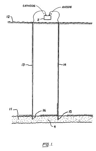
[0010] FIG. 1 is a schematic diagram of an improved electrochemical method for stimulating oil recovery from an underground oil-bearing formation;
[0011] FIG. 2 is a schematic diagram in partial sectional view of an apparatus with which the present method may be practiced;
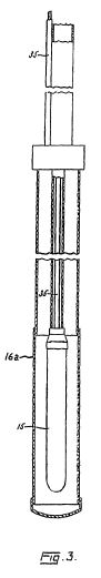
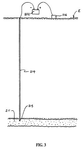
[0012] FIG. 3 is an elevational view of an electrode assembly adapted for use in practicing the present invention;
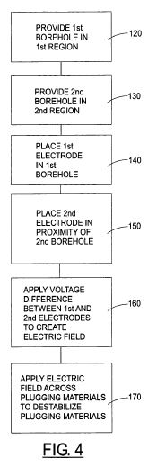
[0013] FIG. 4 is a block flow diagram of a method for improving flow conditions and pre-treating oil in a formation;
[0014] FIG. 5 is a schematic diagram of a first alternate electrochemical method for stimulating oil recovery from an underground oil-bearing formation; and
[0015] FIG. 6 is a schematic diagram of a second alternate electrochemical method for stimulating oil recovery from an underground oil-bearing formation.
DETAILED DESCRIPTION OF THE PREFERRED EMBODIMENT
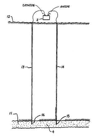
[0016] Referring to the Figures in general, and to FIG. 1, specifically, the reference number 11 represents a subterranean formation containing crude oil. The subterranean formation 11 is an electrically conductive formation, preferably having a moisture content above 5 percent by weight. As shown in FIG. 1, formation 11 is comprised of a porous and substantially homogeneous media, such as sandstone or limestone. Typically, such oil-bearing formations are found beneath the upper strata of earth, referred to generally as overburden, at a depth of the order of 1,000 feet or more below the surface. Communication from the surface 12 to the formation 11 is established through on or more boreholes. In FIG. 1, communication from the surface 12 to the formation 11 is established through spaced-apart boreholes 13 and 14. The hole 13 functions as an oil-producing well, whereas the adjacent hole 14 is a special access hole designed for the transmission of electricity to the formation 11.
[0017] The present invention can be practiced using a multiplicity of cathodes and anodes placed in boreholes. The boreholes may be installed in a variety of vertical, horizontal or angular orientations and configurations. In FIG. 1, the system is shown having two electrodes installed vertically into the ground and spaced apart generally horizontally. A first electrode 15 is lowered through access hole 14 to a location in proximity to formation 11. Preferably, first electrode 15 is lowered through access hole 14 to a medial elevation in formation 11, as shown in FIG. 1. By means of an insulated cable in access hole 14, the relatively positive terminal or anode of a high-voltage d-c electric power source 2 is connected to the first electrode 15. The relatively negative terminal on the power source or cathode is connected to a second electrode 16 in producing well 13, or within close proximity of the producing well. Between the electrodes, the electrical resistance of the connate water 4 in the underground formation 11 is sufficiently low so that current can flow through the formation between the first and second electrodes 15, 16. Although the resistivity of the oil is substantially higher than that of the overburden, the current preferentially passes directly through the formation 11 because this path is much shorter than any path through the overburden to "ground."
[0018] To create the electric field, a periodic voltage is produced between the electrodes 15, 16. Preferably, the voltage is a DC-biased signal with a ripple component produced under modulated AC power. Alternatively, the periodic voltage may be established using pulsed DC power. The voltage may be produced using any technology known in the electrical art. For example, voltage from an AC power supply may be converted to DC using a diode rectifier. The ripple component may be produced using an RC circuit or through transistor controlled power supplies. Once the voltage is established, the electric current is carried by captive water and capillary water present in the underground formation. Electrons are conducted through the formation by naturally occurring electrolytes in the groundwater.
[0019] The electric potential required for carrying out electrochemical reactions varies for different chemical components in the oil. As a result, the desired intensity or magnitude of the ripple component depends on the composition of the oil and the type of reactions that are desired. The magnitude of the ripple component must reach a potential capable of oxidizing and reducing bonds in the oil components. In addition, the ripple component must have a frequency range above 2 hertz and below the frequency at which polarization is no longer induced in the formation. The waveshape of the ripple may be sinusoidal or trapezoidal and either symmetrical or clipped. Frequency of the AC component is preferably between 50 and 2,000 hertz. However, it is understood in the art that pulsing the voltage and tailoring the wave shape may allow the use of frequencies higher than 2,000 hertz.
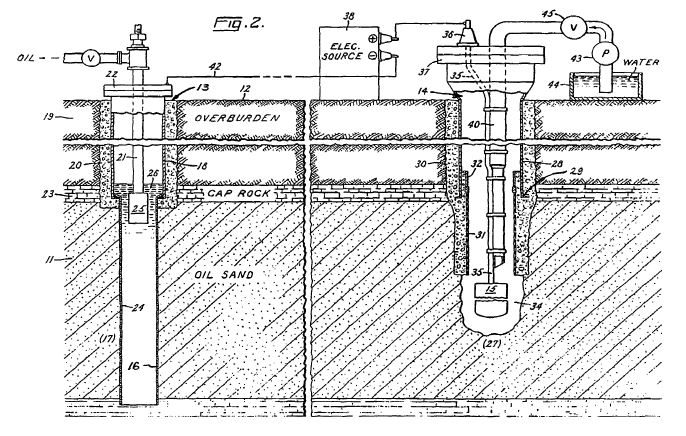
[0020] A system suitable for practicing the invention is shown in FIG. 2. In this system, borehole 13 functions as an oil producing well which penetrates one region 17 of underground oil-bearing formation 11. Well 13 includes an elongated metallic casing 18 extending from the surface 12 to the cap rock 23 immediately above region 17. The casing 18 is sealed in the overburden 19 by concrete 20 as shown, and its lower end is suitably joined to a perforated metallic liner 24 which continues down into the formation 11. Piping 21 is disposed inside the casing 18 where it extends from the casing head 22 to a pump 25 located in the liquid pool 26 that accumulates inside the liner 24. Preferably the producing well 13 is completed in accordance with conventional well construction practice. The pump 25 is selected to operate at sufficient pumping head to draw oil from adjacent formation 11 up through metallic liner 24.
[0021] Access hole 14 that contains first electrode 15 includes an elongated metallic casing 28 with a lower end preferably terminated by a shoe 29 disposed at approximately the same elevation as the cap rock 23. The casing 28 is sealed in the overburden 19 by concrete 30. Near the bottom of hole 14, a tubular liner 31 of electrical insulating material extends from the casing 28 for an appreciable distance into formation 11. The insulating liner 31 is telescopically joined to the casing 28 by a suitable crossover means or coupler 32.
[0022] Below the liner 31, a cavity 34 formed in the oil-bearing formation 11 contains the first electrode 15. The first electrode 15 is supported by a cable 35 that is insulated from ground. The first electrode 15 is relatively short compared to the vertical depth of the underground formation 11 and may be positioned anywhere in proximity to the formation. Referring to FIG. 2, first electrode 15 is positioned at an approximately medial elevation within the oil-bearing formation 11. The first electrode may be exposed to saline or oleaginous fluids in the surrounding earth formation, as well as a high hydrostatic pressure. Under these conditions, first electrode 15 may be subject to electrolytic corrosion. Therefore, the electrode assembly preferably comprises an elongate configuration mounted within a permeable concentric tubular enclosure radially spaced from the electrode body. The enclosure cooperates with the first electrode body to protect it from oil or other adverse materials that enter the cavity.
[0023] It should be noted that FIG. 2 is not to scale, and some of the dimensions of the hole 14 and components in the hole are exaggerated. For example, the diameter of hole 14 is shown to be quite large in comparison to the cable 35 and other components. The diameter of the hole 14 may be much closer to the diameter of the cable 35. In addition, liner 31 preferably has a substantial length and a relatively small inside diameter.
[0024] Referring now to FIG. 3, a preferred assembly for the first electrode 15 is shown. The assembly comprises a hollow tubular electrode body 15 electrically connected through its upper end to a conducting cable 35 and disposed concentrically in radially spaced relation within a permeable tubular enclosure 16a of insulating material. The first electrode 15 is preferably coated externally with a material, such as lead dioxide, which effectively resists electrolytic oxidation. The assembly preferably includes means to place the internal surfaces of the first electrode 15 under pressure substantially equal to the external pressure to which the first electrode is exposed, thereby to preclude deformation and consequent damage to the first electrode. The enclosure 16a is closed at the bottom to provide a receptacle for sand or other foreign material entering from the surrounding formation.
[0025] Referring again to FIG. 2, the first electrode 15 is attached to the lower end of insulated cable 35, the other end of which emerges from a bushing or packing gland 36 in the cap 37 of casing 28 and is connected to the relatively positive terminal of an electric power source 38. The other terminal on the electric power source 38 is connected via a cable 42 to an exposed conductor that acts as a second electrode 16 at the producing well 13. The second electrode 16 may be a separate component installed in the proximity of producing well 13 or may be part of the producing well itself. In the embodiment shown in FIG. 2, the perforated liner 24 serves as the second electrode 16, and the well casing 18 provides a conductive path between the liner and cable 42.
[0026] Thus far, it has been presumed that electrodes 15, 16 are located in a formation with a suitable moisture content and naturally occurring electrolytes to provide an electroconductive path through the formation. In formations that do not have adequate capillary and captive groundwater to be electrically conductive, an electroconductive fluid may be injected into the formation through one or both boreholes to maintain an electroconductive path between the electrodes 15, 16. Referring to FIG. 2, a pipe 40 in borehole 14 delivers electrolyte solution from the ground surface to the underground formation 11. Preferably, a pump 43 is used to convey the solution from a supply 44 and through a control valve 45 into borehole 14. Borehole 14 is preferably equipped with conventional flow and level control devices so as to control the volume of electrolyte solution introduced to the borehole. A detailed system and procedure for injecting electrolyte solution into a formation is described in the aforementioned U.S. Pat. No. 3,782,465. See also, U.S. Pat. No. 5,074,986, the entire disclosure of which is incorporated by reference herein.
[0027] Referring now to FIGS. 1-2, the steps for practicing the improved method for stimulating oil recovery will now be described. An electric potential is applied to first electrode 15 so as to raise its voltage with respect to the second electrode 16 and region 17 of the formation 11 where the producing well 13 is located. The voltage between the electrodes 15, 16 is preferably no less than 0.4 V per meter of electrode distance. Current flows between the first and second electrodes 15, 16 through the formation 11. Connate water 4 in the interstices of the oil formation provides a path for current flow. Water that collects above the electrodes in the boreholes does not cause a short circuit between the electrodes and surrounding casings. Such short circuiting is prevented because the water columns in the boreholes have relatively small cross sectional areas and, consequently, greater resistances than the oil formation.
[0028] As current is applied across formation 11, electrolysis in the capillary water and captive water takes place. Water electrolysis in the groundwater releases agents that promote oxidation and reduction reactions in the oil. That is, negatively charged interfaces of oil compounds undergo cathodic reduction, and positively charged interfaces of the oil compounds undergo anodic oxidation. These redox reactions split long-chain hydrocarbons and multi-cyclic ring compounds into lighter-weight compounds, contributing to lower oil viscosity. Redox reactions may be induced in both aliphatic and aromatic oils. As viscosity of the oil is reduced through redox reactions, the mobility or flow of the oil through the surrounding formation is increased so that the oil may be drawn to the recovery well. Continued application of electric current can ultimately produce carbon dioxide through mineralization of the oil. Dissolution of this carbon dioxide in the oil further reduces viscosity and enhances oil recovery.
[0029] In addition to enhancing oil flow characteristics, the present invention promotes electrochemical reactions that upgrade the quality of the oil being recovered. Some of the electrical energy supplied to the oil formation liberates hydrogen and other gases from the formation. Hydrogen gas that contacts warm oil under hydrostatic pressure can partially hydrogenate the oil, improving the grade and value of the recovered oil. Oxidation reactions in the oil can also enhance the quality of the oil through oxygenation.
[0030] Electrochemical reactions are sufficient to decrease oil viscosities and promote oil recovery in most applications. In some instances, however, additional techniques may be required to adequately reduce retentive forces and promote oil recovery from underground formations. As a result, the foregoing method for secondary oil recovery may be used in conjunction with other processes, such as electrothermal recovery or electroosmosis. For instance, electroosmotic pressure can be applied to the oil deposit by switching to straight d-c voltage and increasing the voltage gradient between the electrodes 15, 16. Supplementing electrochemical stimulation with electroosmosis may be conveniently executed, as the two processes use much of the same equipment. A method for employing electroosmosis in oil recovery is described in U.S. Pat. No. 3,782,465.
[0031] Many aspects of the foregoing invention are described in greater detail in related patents, including U.S. Pat. No. 3,724,543, U.S. Pat. No. 3,782,465, U.S. Pat. No. 3,915,819, U.S. Pat. No. 4,382,469, U.S. Pat. No. 4,473,114, U.S. Pat. No. 4,495,990, U.S. Pat. No. 5,595,644 and U.S. Pat. No. 5,738,778, the entire disclosures of which are incorporated by reference herein. Oil formations in which the methods described herein can be applied include, without limitation, those containing heavy oil, kerogen, asphaltinic oil, napthalenic oil and other types of naturally occurring hydrocarbons. In addition, the methods described herein can be applied to both homogeneous and non-homogeneous formations.
[0032] It has been discovered that the method of the present invention can be used to improve the condition of the oil formation and repair damaged or plugged formations where oil flow is impeded. The method can also be applied to pre-treat oil in the formation as it is extracted from the formation.
[0033] Referring now to FIG. 4, a method 110 for improving flow conditions and pre-treating oil in a formation is shown in a block diagram. The method 110 is applicable to a variety of well pump installations that draw material from underground formations, including oil recovery wells. The method 110 utilizes electric current to enhance the production of oil from an oil-bearing formation and improve the flow characteristics within the formation. The improved flow characteristics increase the volume of oil that is recoverable from the formation. Electric current is also applied to modify the properties of the oil in the formation and increase the quality of oil recovered. The decomposition of long-chain compounds decreases the viscosity of the oil compounds and increases oil mobility through the formation such that the oil may be withdrawn at the recovery well. Electrochemical reactions in the formation also upgrade the quality and value of the oil that is ultimately recovered.
[0034] The components used in the present method include many of the same components described in U.S. patent application Ser. No. 10/279,431. The system generally includes two or more electrodes placed in proximity of the oil bearing formation. In systems using only two boreholes, a first borehole and a second borehole are provided within the underground formation, or in proximity of the underground formation. The first and second boreholes may be drilled vertically, horizontally or at any angle that generally follows the formation. A first electrode is placed within the first borehole and a second electrode is placed within or in proximity of the second borehole. Alternatively, the second electrode may be positioned at the earth's surface. A source of voltage is connected to the first and second electrodes. The first and second boreholes may penetrate the body of oil to be recovered, or they may penetrate the formation at a point beyond but in proximity to the body of oil. A voltage difference is applied between the electrodes to create an electric field through the oil bearing formation.
[0035] The method 110 for improving flow conditions and pre-treating oil in an underground formation will now be described in greater detail. A first borehole is provided in a first region of the formation in step 120. A second borehole is provided in a second region of the formation in step 130. A first electrode is placed in the first borehole in step 140, and a second electrode is placed in proximity of the second borehole in step 150. A voltage difference is established between the first and second electrodes to create an electric field across plugging materials in the formation in step 160. The electric field is applied across the plugging materials to destabilize the plugging materials in step 170.
[0036] The method of FIG. 4 may be applied in several ways to improve flow characteristics in a formation. For example, if a mud cake is deposited on the interface between the well bore and the formation, an electric field may be applied to loosen and remove the mud. A negative electrode is placed in the well bore that is blocked by the mud cake, and the electric field is applied across the mud cake. Formation water will can move through the well bore interface toward the negative electrode under the influence of the electric field. As the water moves through the interface, the electroosmotic forces hydrate the mud and gradually dislodge the clay from the well bore to unblock the well.
[0037] The method of FIG. 4 may also be applied to remove plugging materials from fissures within the formation. Plugging materials may include mud or residue from drilling fluid, naturally formed occlusions, or other matter that blocks flow of oil through the interstitial spaces in the formation. The electrode in the well bore may be negatively charged to draw plugging materials into the well bore and out of the formation. Alternatively, the electrode in the well bore may positively charged to repel and push the plugging materials deeper into the formation.
[0038] The electric field can be applied alone or in conjunction with other techniques for unplugging formations. For example, the present method may be used in conjunction with acidizing to dissolve and remove clay plugging materials. An unplugging acid is introduced into the formation, and an electrode in the formation is positively charged. An electric field is applied to drive the unplugging acid into the formation until the acid reaches the plugging materials. Migration of the acid is carried out by electroosmosis, but may be assisted by other means, such as well pumping. The electric field may be used to drive the acid into regions of the formation that cannot be reached through boreholes. If desired, the voltage may be increased to impart resistive heating and decrease viscosity of the plugging materials. Additives may be introduced into the formation to change the electric charge of plugging materials. Once the plugging materials are destabilized, the formation may be backflushed to remove any remnants or byproducts remaining in the formation. One or more well pumps may be operated to establish suction pressure in the well and draw the destabilized plugging materials into the well.
[0039] As noted above, the present invention promotes electrochemical reactions that upgrade the quality of the oil being recovered. For example, the electric field may be used to remove sulfur-containing compounds from crude, thereby improving the quality and value of oil as it is recovered. It has been found that superimposing a variable AC signal with a frequency between 2 Hz and 1.24 MHz on to a DC signal can induce oxidation to convert sulfur compounds to sulfates. The sulfates tend to remain in the formation as the oil is removed. The present invention may also be applied to remove polycyclic aromatic compounds (PAHS) from crude oil. Operation of the electric field to remove sulfur compounds and PAHs may take place prior to extraction of oil, or while the oil is being extracted. The electric field may be applied for a specified period of time. Alternatively, the electric field may be applied until the concentration of sulfur compounds and/or PAHs is reduced below a predetermined limit.
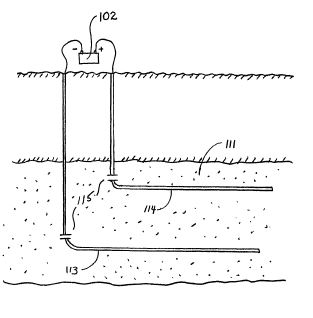
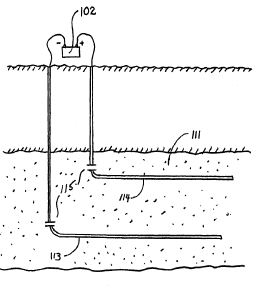
[0040] The present invention can be practiced using a multiplicity of cathodes and anodes placed in vertical, horizontal or angular orientations and configurations, as stated earlier. Referring now to FIG. 5, an alternate system is shown with electrodes installed in well casing 113, 114. The well casings 113, 114 extend in a generally horizontal orientation through an oil-bearing formation 111. The relatively positive terminal or anode of a high-voltage d-c electric power source 102 is connected to the first well casing 113. The relatively negative terminal on the power source or cathode is connected to the second well casing 114. In this arrangement, well casing 113 acts a cathode producer, and well casing 114 acts as an anode. Insulating components or breaks 120 are placed in each of the well casings 113, 114 so that electricity flows between the horizontal sections of the casings within the oil-bearing formation 111. Between the well casings 113, 114, the electrical resistance of the connate water in the formation is sufficiently low so that current can flow through the formation between the casings. Although the resistivity of the oil is substantially higher than that of the overburden, the current preferentially passes directly through the formation 111 because this path is much shorter than any path through the overburden to "ground."
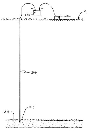
[0041] The present method may include one or more electrodes placed above ground, as described earlier. Referring now to FIG. 6, an alternate system is shown with a first electrode 215 placed below the earth's surface (marked "E") and a second electrode 216 placed above the earth's surface in proximity to an underground oil-bearing formation 211. The first electrode 215 is installed in a borehole 214 that penetrates the formation 211. The first electrode 215 is positioned within the formation, but may be positioned outside the formation, depending on the desired position and range of the electric field. The second electrode 216 is placed on the earth's surface. By means of an insulated cable in access hole 214, a terminal on a high-voltage d-c electric power source 202 is connected to the first electrode 215. The opposite terminal on the power source 202 is connected to the second electrode 216. A voltage difference is established between the first and second electrodes 215, 216 to create an electric field across the formation 211. It should be noted that the second electrode 216 may be installed at a shallow depth just beneath the earth's surface to produce an electric field. For example, the second electrode may be installed within fifty feet of the earth's surface to establish an electric field across the formation. Placing the second electrode 216 at a shallow depth below the earth's surface may be desirable where space above ground is limited.
[0042] The terms and expressions which have been employed are used as terms of description and not of limitation. Although the present invention has been described in detail with reference only to the presently-preferred embodiments, there is no intention in use of such terms and expressions of excluding any equivalents of the features shown and described or portions thereof. It is recognized that various modifications of the embodiments described herein are possible within the scope and spirit of the invention. Accordingly, the invention incorporates variations that fall within the scope of the following claims.
WO0303823
Electrochemical process for effecting redox-enhanced oil recovery
Electrochemical process for effecting redox-enhanced oil recovery
A method is provided for recovering oil from a subterranean oil-bearing formation. One or more pairs of electrodes are inserted into the ground in proximity to a body of oil in said formation. A voltage difference is then established between the electrodes to create an electric field in the oil-bearing formation. As voltage is applied, the current is manipulated to induce oxidation and reduction reactions in components of the oil. The oxidation and reduction reactions lower the viscosity in the oil and thereby reduce capillary resistance to oil flow so that the oil can be removed at an extraction well.
ng earth formation, the oil is forced from the formation into a producing well under the influence of gas pressure and other pressures present in the formation. The stored energy in the reservoir dissipates as oil production progresses and eventually becomes insufficient to force the oil to the producing well. It is well known in the petroleum industry that a relatively small fraction of the oil in subterranean oil reservoirs is recovered during this primary stage of production.
Some reservoirs, such as those containing highly viscous crude, retain 90 percent or more of the oil originally in place after primary production is completed. Oil recovery is frequently limited by capillary forces that impede the flow of viscous oil through interstitial spaces in the oil-bearing formation.
Numerous methods have been proposed for recovering additional oil that remains the in oil-bearing formations following primary production. These secondary recovery
techniques generally involve the expenditure of energy to supplement the expulsive forces and/or to reduce the retentive forces acting on the residual oil. A summary of secondary recovery techniques may be found in U. S. Patent No. 3,782, 465, the entire disclosure of which is incorporated by reference herein.
One secondary recovery technique for promoting oil recovery involves the application of electric current through an oil body to increase oil mobility and facilitate transport to a recovery well. Typically, one or more pairs of electrodes are inserted within the underground formation at spaced-apart locations. A voltage drop is established between the electrodes to create an electric field through the oil formation. In some processes, electric current is applied to raise the temperature of the oil formation and thereby lower the viscosity of the oil to facilitate removal. Other methods use electric current to move the oil towards a recovery well by electroosmosis. In electroosmosis, dissolved electrolytes and suspended. charged particles in the oil migrate toward a cathode, carrying oil molecules with them. These methods typically use a DC potential source to generate an electrical field across the oil-bearing formation.
Oil recovery methods that utilize electrodes frequently encounter problems affecting the quantity and quality of the recovered oil. Systems using straight DC voltage typically operate under high voltages and currents. In addition, systems using DC current consume relatively large amounts of electricity with corresponding large energy costs.
Summary of the Invention
With the foregoing in mind, the present invention provides an improved method for stimulating oil recovery from an oil-bearing underground formation through the use of electric current. Electric current is introduced through a plurality of boreholes installed in the formation. In systems using only two boreholes, a first borehole and a second borehole are provided in the proximity of the underground formation. The boreholes are located at spaced-apart locations in or near the formation. A first electrode is placed into the first borehole and a second electrode is placed into the second borehole. A source of voltage is then connected to the first and second electrodes.
The second borehole may penetrate the body of oil in the underground formation or be located beyond the oil body, so long as some or all of the oil body is located between the second borehole and the first electrode. The first and second boreholes may penetrate the body of oil to be recovered, or they may penetrate the formation at a point beyond but in proximity to the body of oil.
The first and second electrodes are installed in an electrically conductive formation, such as a formation having a moisture content sufficient to conduct electricity. A DC biased current with a ripple component is applied through the electrodes under conditions appropriate to create an electrical field through the oil formation. The current is regulated to stimulate oxidation and reduction reactions in the oil. As redox reactions occur, long-chain compounds such as heavy petroleum hydrocarbons are reduced to smaller-chain compounds. The decomposition of long-chain compounds decreases the viscosity of the oil compounds and increases oil mobility through the formation such that the oil may be withdrawn at the recovery well. Electrochemical reactions in the formation also upgrade the quality and value of the oil that is ultimately recovered. The system can be used with a multiplicity of cathodes and anodes placed in vertical, horizontal or angular orientations and configurations.
US3915819
Electrolytic oil purifying method
Inventor(s): BELL
CHRISTY W; WITTLE JOHN K; SPEECE ARTHUR L +Electrolytic oil purifying method
Sulfur is removed from liquid hydrocarbon oils such as crude oil by subjecting a mixture of the oil and an electrolyte to a direct current field at a relatively high current and low voltage for causing oxidation, reduction or other electrochemical reaction of the sulfur or sulfur-containing material enabling ready separation and removal of the sulfur from the oil.
Sulfur is removed from liquid hydrocarbon oils such as crude oil by subjecting a mixture of the oil and an electrolyte to a direct current field at a relatively high current and low voltage for causing oxidation, reduction or other electrochemical reaction of the sulfur or sulfur-containing material enabling ready separation and removal of the sulfur from the oil.
The present invention relates to the removal of sulfur from hydrocarbon liquids, especially hydrocarbon oils such as crude oil.
It is an object of the present invention to reduce the sulfur content of hydrocarbon liquids, particularly crude oil.
It is another object of the invention to provide a process for purifying crude oil and other hydrocarbon liquids which is readily carried out at relatively low cost.
A particular object of the invention is to provide a process of the above type wherein the sulfur content is reduced by electrochemical means.
Other objects and advantages will become apparent from the following description and the appended claims.
With the above objects in view, the present invention in one of its aspects relates to the method of electro-chemically removing sulfur from hydrocarbon liquids including sulfur-containing materials which comprises mixing the hydrocarbon liquid with an ion-producing compound selected from the group consisting of inorganic electrolytes and ionizing organic solvents, and subjecting the thus obtained mixture to an electrical DC field having a voltage in the range of about 2 to 120 volts and a current of at least about 0.001 amperes per square centimeter, and recovering the hydrocarbon liquid in which the sulfur-containing materials have been substantially reduced.
In general, it has been found in accordance with the invention that the use of relatively high current at low voltages in the electrolyte-oil mixture promotes the oxidation (or reduction, as the case may be) of sulfur contaminants in the oil, resulting in precipitation or volatilization of sulfur compounds which are thereby removed from the oil mixture.
As will be understood, the sulfur components in crude oil may be of various types. It is known that the sulfur content of petroleum may vary from less than 0.1% to 10% by weight depending upon the source. This sulfur may be present as free sulfur, hydrogen sulfide, mercaptans, disulfides, cyclic sulfides or thiophenes. The present refinery methods for removal of sulfur, such as hydro-desulfurization, require the use of relatively cumbersome apparatus and expensive processes. The electrochemical process of this invention, on the other hand, is a relatively simple inexpensive desulfurization method.
In the electrolysis of any particular oil-electrolyte mixture to produce an electrochemical reaction in accordance with the invention, under the same conditions certain sulfur compounds may be oxidized, others may be reduced, some may be precipitated, some may be volatilized and others may be deposited on the electrode surfaces. From experiments carried out in the course of practicing the invention, it appears that oxidation is the predominant reaction, and oxidation products such as sulfonic acids and sulfur oxides have been identified. The reduction of sulfur compounds has been indicated by the production of H2 S volatilized during the process.
The removal or reduction of sulfur in accordance with the principles of the invention may be carried out using various sulfur-containing hydrocarbon liquids or oils mixed with various ion-producing compounds. For example, hydrocarbons such as mineral oil and crude oil from various geographical sources have been satisfactorily treated by the electrochemical process of the invention.
The inorganic electrolyte with which the hydrocarbon liquid may be mixed may be in the form of an aqueous solution of a salt or alkali base in concentrations high enough to obtain an electrically conducting system. Such solutions may contain, for example, a salt or base such as sodium chloride, lithium chloride, potassium chloride, strontium chloride, sodium nitrate, lithium nitrate, potassium nitrate, sodium carbonate, potassium carbonate, calcium carbonate, barium carbonate, sodium hydroxide, potassium hydroxide, calcium hydroxide, and barium hydroxide.
Ionizing organic solvents which may be used in combination with the hydrocarbon liquid include methanol, benzene, nitrobenzene, toluene, xylene, and glacial acetic acid. Many other inorganic and organic compounds will also be found suitable for use in practicing the present invention.
In general, the electrolysis of the oil-electrolyte mixture is carried out in a DC electrical field having a voltage in the range of about 2 to 120 volts and a current of between .001 to 25 amperes per square centimeter, with a preferred voltage range of about 2 to 10 volts being used in most cases. The concentration of the ionizing compound employed in the mixture will depend mainly on the spacing, surface area and configuration of the electrodes. For any particular conditions, the amount of the ionizing material used should be such as to provide a conductivity which results in a voltage of the system in the range set forth above.
The process of the present invention will be illustrated by the following examples, it being understood that the invention is not intended to be limited thereby. In the experiments described below, the electrolysis was carried out in a 100 ml flask equipped with two standard platinum electrodes. The anode was a cylinder of platinum mesh 1/2" in diameter and 2" long. The cathode was a mesh cylinder 13/8" in diameter and 2" long.
EXAMPLE I
A 43.88 gram sample of crude oil designated Fleisher Lease oil containing 6.13% by weight of sulfur was mixed with 54.06 grams of distilled water containing 1.08 grams of reagent grade NaOH. The mixture, which had a pH of 10, was subjected to electrolysis carried out in the above described reaction vessel. The mixture was subjected to a DC electrical field of 0.100--0.175 amperes, for a total of 64 hours. While holding the current to a maximum of 0.175 amperes during the run, the voltage varied between 25 and 200 volts. At the termination of this experiment, it was found that the sulfur content in the oil had been reduced to 4.57%.
EXAMPLE II
A mixture of 7.14 grams of crushed limestone, 49.73 grams distilled water, 43.03 grams of No. 6 fuel oil, and 0.48 gram Ca(OH)2 and 38.78 grams distilled water was placed in the reaction vessel. The mixture separated into an oil layer and water layer. A DC current of 1 ampere was passed through the system at 15 volts for nearly 12 hours, at which time the current had dropped to 0 and the voltage rose to 45 volts. The sulfur content in the oil layer before the electrolysis began was found to be 0.86%, whereas at the end of the experiment the sulfur content was 0.60%.
EXAMPLE III
In this experiment, 46.7 grams of No. 6 fuel oil and 4.55 grams calcium hydroxide were added to 76.58 grams distilled water, and the mixture was heated to reflux without stirring. A direct current of 1 ampere at 9 volts was passed through the solution. The current dropped to 0 within 50 minutes. At this time a surfactant, available commercially under the name Triton X-100, was added to the mixture, and electrolysis was again initiated at 1 ampere and 20 volts. After 4 hours and 20 minutes the voltage had increased to 50 volts at 1 ampere. The system was allowed to run overnight, during which time the current dropped to 0.4 ampere and the voltage increased to 120 volts. The sulfur content of the oil layer before the experiment was 0.86%, and after the experiment was found to be 0.51%.
EXAMPLE IV
To a solution consisting of 92.55 grams distilled water, 0.39 gram Ca(OH)2 and 5.7 grams limestone, there was added 38.75 grams No. 6 fuel oil cut with 10% by weight of pentane to reduce viscosity. The system was subjected to electrolysis at an initial current of 1 ampere and 7 volts. During a period of 6 hours, the current fell to 0 and the voltage increased to 75 volts. The sulfur content of the oil layer was 0.86% before the experiment and was found to be 0.49% after the experiment.
EXAMPLE V
A solution of 1.13 grams Triton X-100, 126.83 grams water and 10.39 grams calcium hydroxide was mixed with 73.95 grams No. 6 fuel oil. The reaction mixture was heated to reflux and electrolysis was started at 1 ampere and 20 volts. Within 2 minutes the voltage had increased to 120 volts and the current dropped to 0.4 ampere. An additional amount of 2.14 grams Triton X-100 was added and electrolysis continued at 1 ampere and 20 volts. After 3 hours the current had dropped to 0.4 ampere and the voltage increased to 120 volts. Again, 2.15 grams Triton X-100 was added and the electrolysis continued at 0.5 ampere and 120 volts. Within 3 hours, the current dropped to 0.2 ampere and the voltage remained at 120 volts. Before the experiment the sulfur content of the oil layer was 0.86% and after the experiment it was 0.54%.
EXAMPLE VI
This was a control experiment which was carried out to determine whether a reduction in sulfur content in the oil can be achieved with a similar mixture is subjected to electrolysis at much higher voltages.
A mixture of 122.12 grams distilled water, 10.14 grams calcium hydroxide, 4.05 grams Triton X-100 and 73.31 grams No. 6 fuel oil was prepared and mechanically agitated for several days. At the end of this period, the oil layer was placed in the previously described reaction vessel and subjected to a 2000 volt per centimeter DC potential for several hours. At the end of this period the oil was analyzed and found to contain the same sulfur content as the original oil content of 0.86% sulfur.
EXAMPLE VII
To a mixture of 15 ml methanol and 51.13 grams mineral oil there was added 8cc of thiophene. This mixture was subjected to electrolysis at 0.1 ampere and 50 volts. The resistance rapidly increased to 30 ohms within 56 minutes and the mixture changed from an initial colorless condition to a yellow color. Gas collected over the reaction mixture indicated SO2 and mercaptans were present. The electrolysis was run intermittently for 4 days. During this time 85 ml methanol was added to maintain liquid level. A total of 8.7 ampere hours of electricity were used. During the last two days of operation, the gas evolved from the reaction was found to contain formaldehyde.
The inside of the reaction vessel and the stirring bar and cathode were covered with a black deposit insoluble in carbon disulfide, the total weight of the deposit being 0.30 gram. No deposit was detected on the anode.
Analysis of the oil layer showed that initially, prior to electrolysis, the sulfur content was 2.30% while the final oil layer had a sulfur content of 0.625%.
EXAMPLE VIII
A sample consisting of 8cc thiophene, 46.12 grams mineral oil and 46.21 grams distilled water containing 1.17 grams sodium hydroxide was mixed and electrolyzed at 0.175 ampere and 4 volts for 15.4 ampere hours. The aqueous layer turned yellow and a gray deposit formed on the anode, while a black deposit formed on the cathode. A brown deposit formed and floated on top of the liquid phases. At the end of the experiment, 42.83 grams of mineral oil, 40.00 grams aqueous phase, 0.54 gram deposit on the anode, 1.23 gram deposit on the cathode and 0.22 gram brown residue were found. Upon standing several days, the oil layer turned sky blue in color. At the start of the experiment, the oil layer had 1.24% sulfur content, and at the end it had 0.20% sulfur. During the experiment, the sulfur content of the aqueous layer had increased from 0 to 2.96%.
EXAMPLE IX
Into the previously described reaction vessel there was introduced 46.14 grams mineral oil, 47.39 grams distilled water containing 1.13 gram calcium hydroxide and 8cc thiophene. A total of 12.86 ampere hours of DC current was passed through the system at 0.2 ampere and 7 volts. A brown solid phase began to separate from the mixture as electrolysis proceeded. The pH of the system was adjusted by the addition of 1.66 grams Ca(OH)2 after 8.56 ampere hours of operation. Just prior to this addition, the generation of gas was noted. At the start of the experiment, the oil layer had 2.71% sulfur and a pH of 12. At the end of the experiment, the oil layer had 0.252% sulfur and the pH was 5.
EXAMPLE X
To a 50.37 gram sample of mineral oil was added 7.75 cc dibutyl disulfide and 43.5 grams methanol. The mixture was electrolyzed at 0.100-0.150 amperes and 50 volts for 64.5 hours or 9.97 ampere hours. During the run no deposits formed on the electrodes and no color changes were noted in the mixture. At the start, the oil layer contained 3.75% sulfur, and at the end of the experiment it contained 2.57% sulfur.
In all of the above experiments the current density of the system was about 0.008 amperes/cm@2. As previously indicated, it is preferable in accordance with the invention to employ a current density of at least 0.001 amperes/cm@2 because it is economically impractical to operate at lower current densities, while a current density of more than 25 amperes/cm@2 is not feasible due to erosion of the anode surface and cavitation on the electrode surface.
The Triton surfactant material mentioned in the Examples was used to emulsify the oil so as to reduce fouling of the electrodes, while at the same reducing the viscosity of the mixture to enhance the electrochemical reaction.
As a result of our experiments, it appeared to be preferable to maintain the pH of the mixture at a relatively high level, i.e., 8-12, since it appeared that the electro-chemical reaction proceeded at a more rapid rate at such a pH level. However, it is not intended to limit the process of the invention to mixtures of such pH levels, since satisfactory results are obtainable at lower pH values. In adjusting the pH by the addition of a base, it is desirable to use compounds such as Ca(OH)2 to form insoluble sulfur-containing compounds to facilitate the separation and removal of these compounds from the mixture.
US2013277046
Method for Enhanced Oil Recovery from Carbonate Reservoirs
Inventor(s): HAROUN
MOHAMMED, et al.Method for Enhanced Oil Recovery from Carbonate Reservoirs
Method of using direct current (DC) electrokinetics to enhance oil production from carbonate reservoirs The method comprising the steps of selecting an underground formation comprising an Oil-bearing carbonate reservoir, positioning two or more electrically conductive elements at spaced apart locations in proximity to said formation, at least one of said conductive elements being disposed in or adjacent to a bore hole affording fluid communication between the interior of said bore hole and said formation, passing a controlled amount of electric current along an electrically conductive path through said formation, said electric current being produced by a DC source including a cathode connected to one of said conductive elements and an anode connected to another of said conductive elements, said electrically conductive path comprising at least one of connate formation water and an aqueous electrolyte introduced into said formation, and withdrawing oil from at least one of said bore holes.
BACKGROUND OF THE INVENTION
[0001] This invention relates to the use of direct current (DC) electrokinetics to enhance oil production from carbonate reservoirs.
[0002] Carbonate formations occur naturally as sediments of carbonate materials, especially calcite (CaCO3) and dolomite (CaMg(CO3)2). They are anionic complexes of (CO3)<2- >and divalent metallic cations such as calcium, magnesium, iron, zinc, barium, strontium and copper, along with a few other less common elements. Carbonates form within the basin of deposition by biological, chemical and detrital processes and are largely made up of skeletal remains and other biological constituents that include fecal pellets, lime mud (skeletal) and microbially mediated cements and lime mud. A main difference between carbonates and silicious soils is that in carbonates chemical constituents, including coated grains such as ooids and pisoids, cement and lime mud are common, whereas they are not present in most siliciclastic sediments. Carbonate reservoirs owe their porosity and permeability to processes of deposition, diagenesis or fracturing.
[0003] Petroleum reservoirs in carbonate formations are porous, permeable rock bodies that contain significant amounts of hydrocarbons. It has been estimated that as much as 60% of the world's oil reserves are present in carbonate reservoirs. However, a substantial portion of these reserves is considered unrecoverable. Among many factors that have contributed to the low recovery rates experienced in these reservoirs, the oil-wettable nature of carbonate rock is particularly problematic. Wettability is generally referred to as the tendency of one fluid to spread on or adhere to a solid surface in the presence of other immiscible fluids. A published report of an evaluation of carbonate reservoir rock cores obtained from all over the world showed that a vast majority of carbonates are oil-wet. Chilingar and Yen, Energy Sources, 7(1): 21-27 (1992).
[0004] Knowledge of the wettability of reservoir rock is important, e.g., for making an informed decision about the use of gas injection or water flooding as an appropriate secondary oil recovery means. A water flooding application to stimulate oil-wet rock would be considerably less efficient than if applied to water-wet rock.
[0005] Various attempts have been made to alter the wettability and thereby provide enhanced oil recovery from carbonate reservoirs. One such approach involves chemically-enhanced oil recovery from in which a surfactant is used to modify wettability of the matrix rock to be more water-wet, as described in U.S. Pat. No. 7,581,594. Another technique entails the use of imbibing fluids which have the effect of modifying the concentration of potential determining ions that influence the surface charge of carbonate rock, so as to improve its water-wetting nature. Zhang and Austad, Colloids and Surfactants A: Physicochemical and Engineering Aspects, 279(1-3): 179-87 (2006). See also U.S. Pat. No. 4,491,512.
[0006] A number of methodologies have been considered for enhanced recovery of high viscosity or “heavy” oil. Low-frequency alternating current (AC) heating has been evaluated in Canadian heavy oil fields. Electro-magnetic (EM) and radiofrequency (RF) induction have been proposed for near well bore heating to reduce oil viscosity. Down-hole resistive heaters have also been suggested for heating the near well bore reservoir rocks. The research and development affiliates of several major oil companies have investigated various AC, RF and down-hole heaters for enhanced oil recovery. None of these approaches have produced consistent results.
[0007] Enhanced oil recovery has been achieved by DC electrical stimulation. See, e.g., U.S. Pat. Nos. 6,877,556, 7,322,409 and 7,325,604, which are commonly owned with the present application. To date, this technique has been shown to be effective in formations composed primarily of either sandstone or unconsolidated sand.
[0008] Insofar as is known, the use of DC electrokinetics for hydrocarbon recovery enhancement in a carbonate rock reservoir has not previously been proposed.
SUMMARY OF THE INVENTION
[0009] In one aspect, the present invention provides an efficient and effective method of enhancing oil recovery from a carbonate reservoir.
[0010] This method comprises selecting an underground formation comprising an oil-bearing carbonate reservoir, positioning two or more electrically conductive elements at spaced apart locations in proximity to the formation, at least one of the conductive elements being disposed in or adjacent to a bore hole affording fluid communication between the bore hole interior and the formation, passing a controlled amount of electric current along an electrically conductive path through the formation and withdrawing oil from at least one of the bore holes. The electric current applied in carrying out this method is produced by a DC source including a cathode connected to one of the conductive elements and an anode connected to another of the conductive elements, and the electrically conductive path comprises at least one of connate formation water and an aqueous electrolyte introduced into the formation.
[0011] In another aspect, the present invention provides a method of fracturing an oil-bearing carbonate rock formation by subjecting the formation to long term electrical stress.
[0012] The invention described herein is believed to be the first technically feasible method using electrokinetic phenomena to enhance oil recovery from a carbonate reservoir.
US7325604
Method for enhancing oil production using electricity
Method for enhancing oil production using electricity
A
method of enhancing oil production from an oil bearing
formation includes the steps of providing a first borehole
in a first region of the formation and a second borehole in
a second region of the formation. A first electrode is
positioned in the first borehole in the first region, and a
second electrode is positioned in proximity to the second
borehole in the second region. A voltage difference is
established between the first and second electrodes to
create an electric field across the plugging materials. The
electric field is applied to destabilize the plugging
materials and improve oil flow through the formation.
FIELD OF THE INVENTION
The present invention relates generally to oil production, and more particularly to a method for enhancing the production of oil from subterranean oil reservoirs with the aid of electric current.
BACKGROUND
When crude oil is initially recovered from an oil-bearing earth formation, the oil is forced from the formation into a producing well under the influence of gas pressure and other pressures present in the formation. The stored energy in the reservoir dissipates as oil production progresses and eventually becomes insufficient to force the oil to the producing well. It is well known in the petroleum industry that a relatively small fraction of the oil in subterranean oil reservoirs is recovered during this primary stage of production. Some reservoirs, such as those containing highly viscous crude, retain 90 percent or more of the oil originally in place after primary production is completed.
A variety of conditions in the oil-bearing formation can impede the flow of oil through interstitial spaces in the oil-bearing formation, limiting the recovery of oil. In many cases, formations become damaged during the process of drilling wells into the formation. Mud, chemical additives and other components used in drilling fluids can accumulate around the well, forming a cake that blocks the flow of oil into the well bore. Drilling fluids can also migrate and accumulate in fissures in the formation, blocking the flow of oil through the formation. Parrafins and waxes may precipitate at the interface between the well bore and the formation, further impeding the flow of oil into the well bore. Sediments and native materials in the formation can also migrate and block interstitial spaces.
Numerous methods have been used to alleviate the problems associated with plugging in oil bearing formations. Plugging is often addressed by backflushing the well to remove mud from around the well. Backflushing the well can consume significant time and energy, and has limited effectiveness in unplugging areas that are located deep within a formation and away from the well. Acidizing the well and flushing the well with solvents are also used to alleviate plugging, but these methods can create hazardous waste that is expensive and difficult to dispose of. As a result, known methods for unplugging oil bearing formations leave much to be desired.
In many cases, crude oil is extracted with high concentrations of sulfur, polycyclic aromatic compounds (PAHs) and other compounds that reduce the quality and value of the oil. The presence of undesirable compounds in the oil requires subsequent processing of the oil, increasing the time and cost of production. Therefore, there is a great need to develop oil production methods that allow oil to be treated while it is being extracted.
SUMMARY OF THE INVENTION
The foregoing problems are solved to a great degree by the present invention, which uses electrodes to enhance oil production from an oil bearing formation. A first borehole is provided in a first region of the formation, and a first electrode is positioned in the first borehole. A second electrode may be placed above ground in proximity to the formation. Alternatively, the second electrode may be installed in a second borehole. The second borehole may be positioned in a second region of the formation, or in proximity to the formation. A voltage difference is established between the first and second electrodes to create an electric field across the formation.
It has been discovered that the method of the present invention can be used to improve the condition of the oil formation and repair damaged or plugged formations where oil flow is impeded by drilling fluids, natural occlusions or other matter. The method can also be applied to pre-treat oil in the formation as it is extracted from the formation. The electric field may be applied and manipulated to destabilize occlusions and plugging materials, increase oil flow through the formation and improve the quality of the oil prior to and during extraction.
DESCRIPTION OF THE DRAWINGS
The foregoing summary as well as the following description will be better understood when read in conjunction with the figures in which:
FIG. 1 is a schematic diagram of an improved electrochemical method for stimulating oil recovery from an underground oil-bearing formation;
FIG. 2 is a schematic diagram in partial sectional view of an apparatus with which the present method may be practiced;
FIG. 3 is an elevational view of an electrode assembly adapted for use in practicing the present invention;
FIG. 4 is a block flow diagram of a method for improving flow conditions and pre-treating oil in a formation;
FIG. 5 is a schematic diagram of a first alternate electrochemical method for stimulating oil recovery from an underground oil-bearing formation; and
FIG. 6 is a schematic diagram of a second alternate electrochemical method for stimulating oil recovery from an underground oil-bearing formation.
DETAILED DESCRIPTION OF THE PREFERRED EMBODIMENT
Referring to the Figures in general, and to FIG. 1, specifically, the reference number 11 represents a subterranean formation containing crude oil. The subterranean formation 11 is an electrically conductive formation, preferably having a moisture content above 5 percent by weight. As shown in FIG. 1, formation 11 is comprised of a porous and substantially homogeneous media, such as sandstone or limestone. Typically, such oil-bearing formations are found beneath the upper strata of earth, referred to generally as overburden, at a depth of the order of 1,000 feet or more below the surface. Communication from the surface 12 to the formation 11 is established through on or more boreholes. In FIG. 1, communication from the surface 12 to the formation 11 is established through spaced-apart boreholes 13 and 14. The hole 13 functions as an oil-producing well, whereas the adjacent hole 14 is a special access hole designed for the transmission of electricity to the formation 11.
The present invention can be practiced using a multiplicity of cathodes and anodes placed in boreholes. The boreholes may be installed in a variety of vertical, horizontal or angular orientations and configurations. In FIG. 1, the system is shown having two electrodes installed vertically into the ground and spaced apart generally horizontally. A first electrode 15 is lowered through access hole 14 to a location in proximity to formation 11. Preferably, first electrode 15 is lowered through access hole 14 to a medial elevation in formation 11, as shown in FIG. 1. By means of an insulated cable in access hole 14, the relatively positive terminal or anode of a high-voltage d-c electric power source 2 is connected to the first electrode 15. The relatively negative terminal on the power source or cathode is connected to a second electrode 16 in producing well 13, or within close proximity of the producing well. Between the electrodes, the electrical resistance of the connate water 4 in the underground formation 11 is sufficiently low so that current can flow through the formation between the first and second electrodes 15, 16. Although the resistivity of the oil is substantially higher than that of the overburden, the current preferentially passes directly through the formation 11 because this path is much shorter than any path through the overburden to "ground."
To create the electric field, a periodic voltage is produced between the electrodes 15, 16. Preferably, the voltage is a DC-biased signal with a ripple component produced under modulated AC power. Alternatively, the periodic voltage may be established using pulsed DC power. The voltage may be produced using any technology known in the electrical art. For example, voltage from an AC power supply may be converted to DC using a diode rectifier. The ripple component may be produced using an RC circuit or through transistor controlled power supplies. Once the voltage is established, the electric current is carried by captive water and capillary water present in the underground formation. Electrons are conducted through the formation by naturally occurring electrolytes in the groundwater.
The electric potential required for carrying out electrochemical reactions varies for different chemical components in the oil. As a result, the desired intensity or magnitude of the ripple component depends on the composition of the oil and the type of reactions that are desired. The magnitude of the ripple component must reach a potential capable of oxidizing and reducing bonds in the oil components. In addition, the ripple component must have a frequency range above 2 hertz and below the frequency at which polarization is no longer induced in the formation. The waveshape of the ripple may be sinusoidal or trapezoidal and either symmetrical or clipped. Frequency of the AC component is preferably between 50 and 2,000 hertz. However, it is understood in the art that pulsing the voltage and tailoring the wave shape may allow the use of frequencies higher than 2,000 hertz.
A system suitable for practicing the invention is shown in FIG. 2. In this system, borehole 13 functions as an oil producing well which penetrates one region 17 of underground oil-bearing formation 11. Well 13 includes an elongated metallic casing 18 extending from the surface 12 to the cap rock 23 immediately above region 17. The casing 18 is sealed in the overburden 19 by concrete 20 as shown, and its lower end is suitably joined to a perforated metallic liner 24 which continues down into the formation 11. Piping 21 is disposed inside the casing 18 where it extends from the casing head 22 to a pump 25 located in the liquid pool 26 that accumulates inside the liner 24. Preferably the producing well 13 is completed in accordance with conventional well construction practice. The pump 25 is selected to operate at sufficient pumping head to draw oil from adjacent formation 11 up through metallic liner 24.
Access hole 14 that contains first electrode 15 includes an elongated metallic casing 28 with a lower end preferably terminated by a shoe 29 disposed at approximately the same elevation as the cap rock 23. The casing 28 is sealed in the overburden 19 by concrete 30. Near the bottom of hole 14, a tubular liner 31 of electrical insulating material extends from the casing 28 for an appreciable distance into formation 11. The insulating liner 31 is telescopically joined to the casing 28 by a suitable crossover means or coupler 32.
Below the liner 31, a cavity 34 formed in the oil-bearing formation 11 contains the first electrode 15. The first electrode 15 is supported by a cable 35 that is insulated from ground. The first electrode 15 is relatively short compared to the vertical depth of the underground formation 11 and may be positioned anywhere in proximity to the formation. Referring to FIG. 2, first electrode 15 is positioned at an approximately medial elevation within the oil-bearing formation 11. The first electrode may be exposed to saline or oleaginous fluids in the surrounding earth formation, as well as a high hydrostatic pressure. Under these conditions, first electrode 15 may be subject to electrolytic corrosion. Therefore, the electrode assembly preferably comprises an elongate configuration mounted within a permeable concentric tubular enclosure radially spaced from the electrode body. The enclosure cooperates with the first electrode body to protect it from oil or other adverse materials that enter the cavity.
It should be noted that FIG. 2 is not to scale, and some of the dimensions of the hole 14 and components in the hole are exaggerated. For example, the diameter of hole 14 is shown to be quite large in comparison to the cable 35 and other components. The diameter of the hole 14 may be much closer to the diameter of the cable 35. In addition, liner 31 preferably has a substantial length and a relatively small inside diameter.
Referring now to FIG. 3, a preferred assembly for the first electrode 15 is shown. The assembly comprises a hollow tubular electrode body 15 electrically connected through its upper end to a conducting cable 35 and disposed concentrically in radially spaced relation within a permeable tubular enclosure 16a of insulating material. The first electrode 15 is preferably coated externally with a material, such as lead dioxide, which effectively resists electrolytic oxidation. The assembly preferably includes means to place the internal surfaces of the first electrode 15 under pressure substantially equal to the external pressure to which the first electrode is exposed, thereby to preclude deformation and consequent damage to the first electrode. The enclosure 16a is closed at the bottom to provide a receptacle for sand or other foreign material entering from the surrounding formation.
Referring again to FIG. 2, the first electrode 15 is attached to the lower end of insulated cable 35, the other end of which emerges from a bushing or packing gland 36 in the cap 37 of casing 28 and is connected to the relatively positive terminal of an electric power source 38. The other terminal on the electric power source 38 is connected via a cable 42 to an exposed conductor that acts as a second electrode 16 at the producing well 13. The second electrode 16 may be a separate component installed in the proximity of producing well 13 or may be part of the producing well itself. In the embodiment shown in FIG. 2, the perforated liner 24 serves as the second electrode 16, and the well casing 18 provides a conductive path between the liner and cable 42.
Thus far, it has been presumed that electrodes 15, 16 are located in a formation with a suitable moisture content and naturally occurring electrolytes to provide an electroconductive path through the formation. In formations that do not have adequate capillary and captive groundwater to be electrically conductive, an electroconductive fluid may be injected into the formation through one or both boreholes to maintain an electroconductive path between the electrodes 15, 16. Referring to FIG. 2, a pipe 40 in borehole 14 delivers electrolyte solution from the ground surface to the underground formation 11. Preferably, a pump 43 is used to convey the solution from a supply 44 and through a control valve 45 into borehole 14. Borehole 14 is preferably equipped with conventional flow and level control devices so as to control the volume of electrolyte solution introduced to the borehole. A detailed system and procedure for injecting electrolyte solution into a formation is described in the aforementioned U.S. Pat. No. 3,782,465. See also, U.S. Pat. No. 5,074,986, the entire disclosure of which is incorporated by reference herein.
Referring now to FIGS. 1-2, the steps for practicing the improved method for stimulating oil recovery will now be described. An electric potential is applied to first electrode 15 so as to raise its voltage with respect to the second electrode 16 and region 17 of the formation 11 where the producing well 13 is located. The voltage between the electrodes 15, 16 is preferably no less than 0.4 V per meter of electrode distance. Current flows between the first and second electrodes 15, 16 through the formation 11. Connate water 4 in the interstices of the oil formation provides a path for current flow. Water that collects above the electrodes in the boreholes does not cause a short circuit between the electrodes and surrounding casings. Such short circuiting is prevented because the water columns in the boreholes have relatively small cross sectional areas and, consequently, greater resistances than the oil formation.
As current is applied across formation 11, electrolysis in the capillary water and captive water takes place. Water electrolysis in the groundwater releases agents that promote oxidation and reduction reactions in the oil. That is, negatively charged interfaces of oil compounds undergo cathodic reduction, and positively charged interfaces of the oil compounds undergo anodic oxidation. These redox reactions split long-chain hydrocarbons and multi-cyclic ring compounds into lighter-weight compounds, contributing to lower oil viscosity. Redox reactions may be induced in both aliphatic and aromatic oils. As viscosity of the oil is reduced through redox reactions, the mobility or flow of the oil through the surrounding formation is increased so that the oil may be drawn to the recovery well. Continued application of electric current can ultimately produce carbon dioxide through mineralization of the oil. Dissolution of this carbon dioxide in the oil further reduces viscosity and enhances oil recovery.
In addition to enhancing oil flow characteristics, the present invention promotes electrochemical reactions that upgrade the quality of the oil being recovered. Some of the electrical energy supplied to the oil formation liberates hydrogen and other gases from the formation. Hydrogen gas that contacts warm oil under hydrostatic pressure can partially hydrogenate the oil, improving the grade and value of the recovered oil. Oxidation reactions in the oil can also enhance the quality of the oil through oxygenation.
Electrochemical reactions are sufficient to decrease oil viscosities and promote oil recovery in most applications. In some instances, however, additional techniques may be required to adequately reduce retentive forces and promote oil recovery from underground formations. As a result, the foregoing method for secondary oil recovery may be used in conjunction with other processes, such as electrothermal recovery or electroosmosis. For instance, electroosmotic pressure can be applied to the oil deposit by switching to straight d-c voltage and increasing the voltage gradient between the electrodes 15, 16. Supplementing electrochemical stimulation with electroosmosis may be conveniently executed, as the two processes use much of the same equipment. A method for employing electroosmosis in oil recovery is described in U.S. Pat. No. 3,782,465.
Many aspects of the foregoing invention are described in greater detail in related patents, including U.S. Pat. No. 3,724,543, U.S. Pat. No. 3,782,465, U.S. Pat. No. 3,915,819, U.S. Pat. No. 4,382,469, U.S. Pat. No. 4,473,114, U.S. Pat. No. 4,495,990, U.S. Pat. No. 5,595,644 and U.S. Pat. No. 5,738,778, the entire disclosures of which are incorporated by reference herein. Oil formations in which the methods described herein can be applied include, without limitation, those containing heavy oil, kerogen, asphaltinic oil, napthalenic oil and other types of naturally occurring hydrocarbons. In addition, the methods described herein can be applied to both homogeneous and non-homogeneous formations.
It has been discovered that the method of the present invention can be used to improve the condition of the oil formation and repair damaged or plugged formations where oil flow is impeded. The method can also be applied to pre-treat oil in the formation as it is extracted from the formation.
Referring now to FIG. 4, a method 110 for improving flow conditions and pre-treating oil in a formation is shown in a block diagram. The method 110 is applicable to a variety of well pump installations that draw material from underground formations, including oil recovery wells. The method 110 utilizes electric current to enhance the production of oil from an oil-bearing formation and improve the flow characteristics within the formation. The improved flow characteristics increase the volume of oil that is recoverable from the formation. Electric current is also applied to modify the properties of the oil in the formation and increase the quality of oil recovered. The decomposition of long-chain compounds decreases the viscosity of the oil compounds and increases oil mobility through the formation such that the oil may be withdrawn at the recovery well. Electrochemical reactions in the formation also upgrade the quality and value of the oil that is ultimately recovered.
The components used in the present method include many of the same components described in U.S. patent application Ser. No. 10/279,431. The system generally includes two or more electrodes placed in proximity of the oil bearing formation. In systems using only two boreholes, a first borehole and a second borehole are provided within the underground formation, or in proximity of the underground formation. The first and second boreholes may be drilled vertically, horizontally or at any angle that generally follows the formation. A first electrode is placed within the first borehole and a second electrode is placed within or in proximity of the second borehole. Alternatively, the second electrode may be positioned at the earth's surface. A source of voltage is connected to the first and second electrodes. The first and second boreholes may penetrate the body of oil to be recovered, or they may penetrate the formation at a point beyond but in proximity to the body of oil. A voltage difference is applied between the electrodes to create an electric field through the oil bearing formation.
The method 110 for improving flow conditions and pre-treating oil in an underground formation will now be described in greater detail. A first borehole is provided in a first region of the formation in step 120. A second borehole is provided in a second region of the formation in step 130. A first electrode is placed in the first borehole in step 140, and a second electrode is placed in proximity of the second borehole in step 150. A voltage difference is established between the first and second electrodes to create an electric field across plugging materials in the formation in step 160. The electric field is applied across the plugging materials to destabilize the plugging materials in step 170.
The method of FIG. 4 may be applied in several ways to improve flow characteristics in a formation. For example, if a mud cake is deposited on the interface between the well bore and the formation, an electric field may be applied to loosen and remove the mud. A negative electrode is placed in the well bore that is blocked by the mud cake, and the electric field is applied across the mud cake. Formation water will can move through the well bore interface toward the negative electrode under the influence of the electric field. As the water moves through the interface, the electroosmotic forces hydrate the mud and gradually dislodge the clay from the well bore to unblock the well.
The method of FIG. 4 may also be applied to remove plugging materials from fissures within the formation. Plugging materials may include mud or residue from drilling fluid, naturally formed occlusions, or other matter that blocks flow of oil through the interstitial spaces in the formation. The electrode in the well bore may be negatively charged to draw plugging materials into the well bore and out of the formation. Alternatively, the electrode in the well bore may positively charged to repel and push the plugging materials deeper into the formation.
The electric field can be applied alone or in conjunction with other techniques for unplugging formations. For example, the present method may be used in conjunction with acidizing to dissolve and remove clay plugging materials. An unplugging acid is introduced into the formation, and an electrode in the formation is positively charged. An electric field is applied to drive the unplugging acid into the formation until the acid reaches the plugging materials. Migration of the acid is carried out by electroosmosis, but may be assisted by other means, such as well pumping. The electric field may be used to drive the acid into regions of the formation that cannot be reached through boreholes. If desired, the voltage may be increased to impart resistive heating and decrease viscosity of the plugging materials. Additives may be introduced into the formation to change the electric charge of plugging materials. Once the plugging materials are destabilized, the formation may be backflushed to remove any remnants or byproducts remaining in the formation. One or more well pumps may be operated to establish suction pressure in the well and draw the destabilized plugging materials into the well.
As noted above, the present invention promotes electrochemical reactions that upgrade the quality of the oil being recovered. For example, the electric field may be used to remove sulfur-containing compounds from crude, thereby improving the quality and value of oil as it is recovered. It has been found that superimposing a variable AC signal with a frequency between 2 Hz and 1.24 MHz on to a DC signal can induce oxidation to convert sulfur compounds to sulfates. The sulfates tend to remain in the formation as the oil is removed. The present invention may also be applied to remove polycyclic aromatic compounds (PAHS) from crude oil. Operation of the electric field to remove sulfur compounds and PAHs may take place prior to extraction of oil, or while the oil is being extracted. The electric field may be applied for a specified period of time. Alternatively, the electric field may be applied until the concentration of sulfur compounds and/or PAHs is reduced below a predetermined limit.
The present invention can be practiced using a multiplicity of cathodes and anodes placed in vertical, horizontal or angular orientations and configurations, as stated earlier. Referring now to FIG. 5, an alternate system is shown with electrodes installed in well casing 113, 114. The well casings 113, 114 extend in a generally horizontal orientation through an oil-bearing formation 111. The relatively positive terminal or anode of a high-voltage d-c electric power source 102 is connected to the first well casing 113. The relatively negative terminal on the power source or cathode is connected to the second well casing 114. In this arrangement, well casing 113 acts as a cathode producer, and well casing 114 acts as an anode. Insulating components or breaks 115 are placed in each of the well casings 113, 114 so that electricity flows between the horizontal sections of the casings within the oil-bearing formation 111. Between the well casings 113, 114, the electrical resistance of the connate water in the formation is sufficiently low so that current can flow through the formation between the casings. Although the resistivity of the oil is substantially higher than that of the overburden, the current preferentially passes directly through the formation 111 because this path is much shorter than any path through the overburden to "ground."
The present method may include one or more electrodes placed above ground, as described earlier. Referring now to FIG. 6, an alternate system is shown with a first electrode 215 placed below the earth's surface (marked "E") and a second electrode 216 placed above the earth's surface in proximity to an underground oil-bearing formation 211. The first electrode 215 is installed in a borehole 214 that penetrates the formation 211. The first electrode 215 is positioned within the formation, but may be positioned outside the formation, depending on the desired position and range of the electric field. The second electrode 216 is placed on the earth's surface. By means of an insulated cable in access hole 214, a terminal on a high-voltage d-c electric power source 202 is connected to the first electrode 215. The opposite terminal on the power source 202 is connected to the second electrode 216. A voltage difference is established between the first and second electrodes 215, 216 to create an electric field across the formation 211. It should be noted that the second electrode 216 may be installed at a shallow depth just beneath the earth's surface to produce an electric field. For example, the second electrode may be installed within fifty feet of the earth's surface to establish an electric field across the formation. Placing the second electrode 216 at a shallow depth below the earth's surface may be desirable where space above ground is limited.
US2005161217
Method and system for producing methane gas from methane hydrate formations
Method and system for producing methane gas from methane hydrate formations
A system for producing gas from a gas hydrate formation includes a first electrode and a second electrode. The first electrode is disposed in proximity of a first region of the formation, and the second electrode is disposed within a second region of the formation. The second electrode is separated from the first electrode by an electro-conductive path through the formation. An extraction well extends within the formation and intersects the electro-conductive path. The well comprises one or more perforations in fluid communication with the formation. A voltage source is connected to the electrodes and operates to produce a voltage difference across the electrodes.; A method for extracting gases from a gas hydrate formation includes the step of establishing a voltage difference across two or more electrodes in a hydrate formation to thermally react with the hydrate formation and release gas from the formation.
CROSS-REFERENCE TO RELATED APPLICATIONS
[0001] This is a continuation-in part of U.S. patent application Ser. No. 10/279,431, filed Oct. 24, 2002, which claims the benefit of U.S. Provisional Application No. 60/335,701, filed Oct. 26, 2001, the entire disclosures of which are incorporated by reference herein.
FIELD OF THE INVENTION
[0002] The present invention relates generally to the production of natural gas, and more particularly to a method and system for producing natural gas from gas reserves with the aid of electric current.
BACKGROUND
[0003] The U.S. Department of Energy estimates that the ocean floor and arctic permafrost regions contain several trillion cubic feet of methane gas (also referred to as natural gas) in the form of methane hydrates. Methane hydrates are clathrate compounds which are inclusion complexes formed at high pressures and low temperatures, existing as solid crystalline structures. In these structures, methane gas molecules are surrounded or included by a cage of water molecules. Methane hydrates are typically found on the ocean floor in sediments which are stable at depths of approximately 300 meters.
[0004] There is increasing interest in the development of methods to extract methane gas from formations containing methane hydrates. The production of methane gas is viewed as one means for lessening global dependency on oil and other fuels containing large amounts of carbon. Efforts to increase methane gas production are also motivated by an expanding natural gas infrastructure and growing interest in natural gas from public utility companies. At least one extraction technique, solvent injection, has been proposed and tested to extract methane gas from methane hydrates. Although solvent injection has shown promise, the technique is difficult to apply uniformly through a formation, and may not be suitable for deep formations. As a result, currently proposed techniques for extracting methane gas from methane hydrate formations leave much to be desired.
SUMMARY OF THE INVENTION
[0005] In a first aspect of the invention, a system for extracting gases from a gas hydrate formation includes a first electrode and a second electrode. The first electrode is disposed in proximity to a first region of the formation, and the second electrode is disposed within a second region of the formation. The second electrode is separated from the first electrode by an electro-conductive path through the formation. An extraction well extends within the formation in proximity to the electro-conductive path. The well comprises one or more perforations in fluid communication with the formation. A voltage source is connected to the first and second electrodes and operates to produce a voltage difference across the first and second electrodes.
[0006] In one embodiment of the invention, a system includes a first electrode in proximity to a first region of a formation containing methane hydrates on the ocean floor. A second electrode is disposed within a second region of the formation. The second electrode is separated from the first electrode by an electro-conductive path through the methane hydrate formation. An extraction well extends within the formation in proximity to the electro-conductive path. The well comprises one or more perforations in fluid communication with the formation. A voltage source is connected to the first and second electrodes and operates to produce a voltage difference across the first and second electrodes. Upon operation of the voltage source, resistance in the formation causes the voltage difference between the electrodes to generate heat energy which is sufficient to thermally react with the methane hydrates thereby releasing methane gas from the formation. The methane gas is formed at elevated pressure, which drives the gas into the extraction well. The methane gas may be recovered and stored on a barge or other ocean vessel. Once on the barge, the gas may be used to fuel an electric generator. Alternatively, the methane gas may be conveyed by undersea piping to a facility on land e.g. for distribution.
[0007] In a second aspect of the invention, a method for extracting gas from a formation containing gas hydrates includes the step of placing two or more electrodes in proximity to the formation and drilling an extraction well into the formation. The extraction well has one or more perforations to connect the interior of the well with the formation. A source of voltage is connected to the electrodes, and a voltage difference is established across the electrodes to produce an electrical current through the formation. The current through the formation is adjusted to thermally react with the gas hydrates in the formation and release gases from the gas hydrates. Gases released from the gas hydrates are drawn into the extraction well.
DESCRIPTION OF THE DRAWINGS
[0008] The foregoing summary as well as the following description will be better understood when read in conjunction with the figures in which:
[0009] FIG. 1 is a schematic of a system for producing gas from a gas hydrate formation in accordance with the present invention.
[0010] FIG. 2 is a schematic of a system for producing gas from a gas hydrate formation in accordance with the present invention, where the system is employed on an ocean vessel to extract gas from a gas hydrate formation on the ocean floor.
[0011] FIG. 3 is a schematic of an alternate system for producing gas from a gas hydrate formation in accordance with the present invention, where the system is employed on an ocean vessel to extract gas from a gas hydrate formation on the ocean floor.
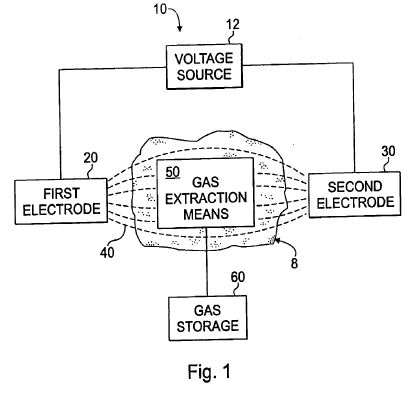
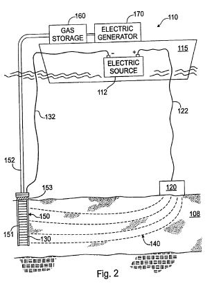
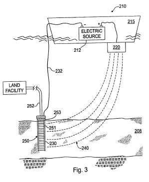
DETAILED DESCRIPTION OF THE PREFERRED EMBODIMENT
[0012] Referring to the drawing figures in general, and to FIG. 1 specifically, a system 10 for producing gas from a formation containing gas hydrates is shown in schematic form in accordance with the present invention. The system 10 is installed in the vicinity of a gas hydrate formation 8. Two or more electrodes, such as a first electrode 20 and a second electrode 30, are placed in or around the gas hydrate formation 8 and connected with a voltage source 12. Electric current is applied between the electrodes 20, 30 and across the gas hydrate formation 8 to produce an electric field 40 across the hydrate formation. The electric field 40 is applied to the formation to release gas from the gas hydrates. The release of gas from the gas hydrates is primarily carried out through resistive heating. The electric field 40 gradually produces heat in the formation 8 based on electrical resistivity of the sediments and materials in the formation 8. As heat is generated, the temperature around the gas hydrates increases until the hydrates are destabilized, releasing the gas from the hydrate molecules. A gas extraction means 50 is placed within the hydrate formation 8 to capture and convey the released gas to a gas collection system 60.
[0013] The system 10 may be used in a variety of applications to produce gas from gas hydrate deposits. For purposes of this description, the system 10 will be shown and described in the context of methane gas production, with the understanding that the invention can be applied to a variety of different gas hydrate formations containing varying amounts of methane and other gases. The present invention is operable in different formations of varying compositions, and may be used for releasing and collecting gases other than methane gas. In addition, while this description refers to methane gas, it is understood that the gas released from a formation will likely contain a mixture of methane gas and other gases.
[0014] The present invention can be practiced using a multiplicity of electrodes placed in vertical, horizontal or angular orientations and configurations. The arrangement of components in a given installation will vary depending on the location and local geology of the hydrate formation. As stated earlier, methane hydrate formations have been studied in arctic permafrost regions as well as in sediment layers on or beneath the ocean floor. Hydrate formations may exist as large relatively flat homogeneous formations, or may be interrupted by outcrops of non-hydrate material. Therefore, the electrodes may be positioned in a number of arrangements in or around the formation.
[0015] Referring now to FIG. 2, a system 110 in accordance with one embodiment of the present invention is operable to produce methane gas from a methane hydrate formation 108 along the sea floor. The system 110 includes a high-voltage electric power source 112 supported above the formation. The components of system 110 may be located on land or supported on a ship, rig, barge, vessel, or other means in proximity to the formation. In FIG. 2, the system is shown on a barge 115. By means of an insulated cable 122, the relatively positive terminal, or anode, of the power source 112 is connected to a first electrode 120. Depending on the geology of the sea floor, and the proximity of the methane hydrate formation to the sea floor surface, the first electrode 120 may be suspended above the sea floor, rest on the sea floor or be installed beneath the sea floor through a fissure, crevice or bore hole that penetrates beneath the sea floor in proximity to the hydrate formation. For purposes of FIG. 2, it will be assumed that a significant volume of stabilized methane hydrate is exposed on the sea floor in a substantially flat layer, allowing the first electrode 120 to rest on the sea floor.
[0016] A gas collection well 150 is drilled into the formation 108 to recover methane gas released from the formation during operation of the system 110. The collection well 150 includes a perforated metallic liner 151 which extends down into the formation 108. The perforated liner 151 has one or more perforations that connect the interior of the collection well 150 in fluid communication with the interior of the formation 108. Since the hydrate formation 108 is exposed on the sea floor, the liner 151 extends from the top of the well 150 into the formation. In hydrate formations that are buried under a layer of overburden material, the well 150 may include a solid casing that extends through the overburden. The specific construction of the well is not germane to the invention, and will largely depend on the geologic conditions around the hydrate formation. Preferably, the collection well 150 is completed in accordance with conventional undersea drilling practices.
[0017] The relatively negative terminal on the power source 112, or cathode, is connected to a second electrode 130 placed within the methane hydrate formation 108. The second electrode 130 may have several forms and be positioned in the formation in several ways. For example, the second electrode could be lowered through large cracks or fissures in the formation. In the preferred embodiment, the second electrode 130 is associated with the gas collection well 150. The second electrode 130 may be a separate component installed inside the collection well 150 or in the proximity of the collection well. Alternatively, the second electrode 130 may be part of the collection well 150 itself. In the embodiment shown in FIG. 2, the perforated metallic liner 151 serves as the second electrode 130. An insulated cable 132 connects the liner 151 with the relatively negative terminal on the power source 112. The top portion of the well 150 forms an electro-conductive path between the insulated cable 132 and the second electrode 130. In this arrangement, an electric field 140 is generated through the formation 108 when a voltage drop is created across the electrodes 120, 130. The gas collection well 150 may be installed to depths of 500 meters or greater to reach the hydrate formation.
[0018] Thus far, the first electrode 120 above the formation has been shown connected to the relatively positive terminal, or anode, of the power source 112, and the second electrode 130 within the formation has been shown connected to the relatively negative terminal, or cathode, of the power source. There is nothing that precludes the first electrode 120 from being connected to the cathode of the power source 112, and nothing to preclude the second electrode 130 from being connected to the anode of the power source, however. Therefore, the electrode in the formation may be connected with either terminal of the voltage source 112.
[0019] The electrical resistance of the sediment in the formation is sufficiently low to allow the passage of current through the formation between the first and second electrodes 120, 130. Although the resistivity of the formation 108 is substantially higher than that of the seawater above the electrodes, the current passes directly through the formation because this path is much shorter than any path through the overlying seawater to "ground." In the preferred embodiment, the second electrode 130 is connected with an insulating break 153 that substantially prevents short circuiting of current up through the well casing.
[0020] To create the electric field 140 and commence resistive heating in the formation, a voltage drop is produced across the electrodes 120, 130. The voltage may be a straight DC voltage or a DC-biased signal with a ripple component produced under modulated AC power. Alternatively, the periodic voltage may be established using pulsed DC power. The voltage may be produced using any technology known in the electrical art. For example, voltage from an AC power supply may be converted to DC using a diode rectifier. The ripple component may be produced using an RC circuit.
[0021] The choice of AC power or DC power depends on many variables, and each option has advantages. One advantage of AC is that AC systems have less potential for corrosion on the electrode than DC. The use of AC also has limitations, including a limited effectiveness at deeper depths. Losses in steel well casings dissipate energy. This dissipation increases with depth, and will typically limit the use of AC to depths of approximately 5,000 feet below the top of the well. Use of AC can be applied at greater depths, but resistive heating may be very limited. Therefore, for well casings and liners extending greater than 5,000 feet, straight DC power is preferable. AC power is desirable in shallower well installations, where losses are less of a factor.
[0022] Where DC power is used to induce destabilization of methane hydrates, the process of producing and recovering methane gas may be enhanced through electro-osmosis and ion migration. In addition, electrochemical reactions such as the production of oxygen and hydrogen may assist in the production of methane. Electrochemical reactions can also create methanol and ethane through oxidation and reduction. The electric potential required for carrying out thermal destabilization of methane hydrates will vary depending on pressure and temperature conditions at the formation, and the size of the desired electric field.
[0023] Referring now to FIG. 3, a system 210 in accordance with the present invention includes a high-voltage electric power source 212 located on a barge 215, and a first electrode 220 incorporated into the structure of the barge. The first electrode 220 is connected to a relatively positive terminal, or anode, of the power source 212. A gas collection well 250 is drilled into a methane hydrate formation 208, similar to the embodiment described above. The collection well 250 includes a perforated metallic liner 251 which extends down into the formation 208 and serves as a second electrode 230. An insulated cable 232 connects the liner 251 with the relatively negative terminal on the power source 212.
[0024] Based on the foregoing, persons skilled in the art will understand the advantages of system 210 over prior methods for producing gas from gas hydrates. The first electrode 220 is integrally connected with the barge 215, while the second electrode 230 is a stationary electrode. The position of the first electrode can be adjusted by navigating the barge in different positions relative to the second electrode 230. By moving the first electrode, the position and intensity of the electric field can be modified. The ability to move electrodes maximizes the range of application of the electric field. Theoretically, the position of the field can be adjusted through an angle of up to 360 degrees around a single stationary electrode. The same benefits may be achieved on land by mounting electrodes on vehicles. For example, it is anticipated that the present invention may be applied in arctic permafrost regions, with electrodes mounted on heavy track machines or all-terrain vehicles. The ability to reposition the electric field greatly reduces the number of bore holes and electrodes that must be installed, since an electric field can be applied over a relatively large area by maneuvering a small number of electrodes around the formation.
[0025] Gas may be captured or collected using a variety of piping arrangements in accordance with the present invention. In FIG. 2, the well 150 is connected to a riser pipe or conduit 152 which connects to a storage tank 160 on the barge 115. In this arrangement, gas can be collected on the barge and transported to shore. The conduit 152 may require special reinforcements or materials suitable for withstanding pressures and currents associated with deep sea installations. These structural reinforcements and materials are generally known and therefore will not be described in detail herein. In addition to storing the gas on the barge 115, the gas may be used to fuel an electric generator 170 installed on the barge. In this type of system, gas may be piped from the extraction well into a storage tank on the barge, and subsequently fed to a boiler to generate steam. Electricity generated on the barge may then be exported to the mainland by undersea cables. The gas may also be piped from the extraction well directly to land. In FIG. 3, the well 250 is connected to undersea piping 252 which transports the gas to a bulk storage plant, power generator, or other facility located on land.
US2799641
Electrolytically promoting the flow of oil from a well
Electrolytically promoting the flow of oil from a well
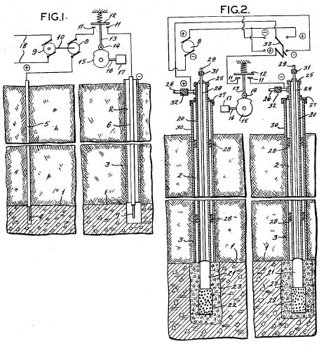
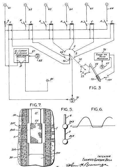
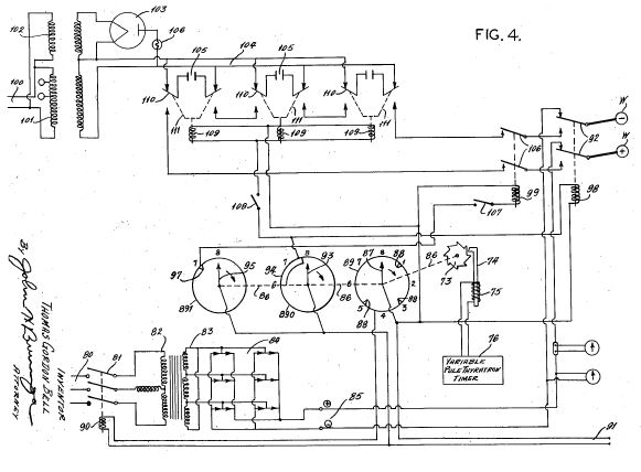
US3417823
Well treating process using electroosmosis
Well treating process using electroosmosis
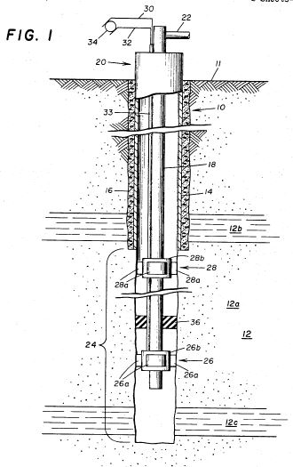
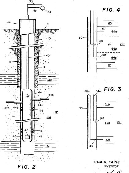
US3724543
Electro-thermal process for production of off shore oil through on shore walls
Electro-thermal process for production of off shore oil through on shore walls
Inventors:
Bell C, Titus C
Abstract
The flow of oil from an undersea oil-bearing formation to an on-shore well is induced by the steps of locating a relatively small anode in a cavity at an approximately medial elevation of the formation at an off-shore location preferably beyond the reservoir of oil, injecting saline water into that cavity, raising the electric potential of the anode with respect to a cathode in the vicinity of an off-shore well, and withdrawing oil from the well.
Crude oil is generally recovered from an oil bearing formation initially as a result of gas or other formation pressure forcing the oil from the formation into a producing well from whence it is pumped to the surface. Such a well of course must penetrate directly into the body of oil contained in the formation and there is consequent risk that oil under natural pressure will be exhausted without control. To preclude or limit such uncontrolled exhaust it is desirable that oil be moved below ground to a well location remote from the pressurized region or to a well location where surface conditions are such that uncontrolled exhaust may be better controlled at least temporarily. Even where natural pressure does not create the risk of uncontrolled exhaust it may often be desirable to move a body of underground oil, whether fluid or highly viscous, to a well location where production by pumping is less expensive or more convenient than it would be directly over the oil body in its natural location.
The several techniques currently used to induce flow of underground oil are primarily adapted to secondary recovery of oil following primary production and may be of limited effectiveness in treating highly viscous oils. A principal such method employs a scavenging fluid such as air, gas, water or steam. In such methods, however, pressure and/or temperature limitations are such that oil flow can be induced only over short distances of the order of several hundred feet and without directional control.
Other prior art techniques for improving oil recovery involve conducting electric current through the oilbearing strata for the purpose of either raising the temperature of the oil by conduction heating or controlling oil movement by electro-osmosis. The latter is described in US Pat. No. 2,799,641 granted on July 16, 1957 to Bell whose proposes placing two electrodes in contact with the oil at spaced apart locations in an oil-bearing formation. Bell teaches that electromotive force must be impressed directly on the oil to cause electric current to flow through the oil and postulates that the oil is induced to move by electro-osmosis toward the cathode. Such a method, of course, requires that both the producing well and the anode bore hole penetrate directly into the body of oil contained in the formation, and there is consequent risk that oil under pressures created naturally or otherwise may exhaust through the anode hole.
The flow of oil from an undersea oil-bearing formation to an on-shore well is induced by the steps of locating a relatively small anode in a cavity at an approximately medial elevation of the formation at an off-shore location preferably beyond the reservoir of oil, injecting saline water into that cavity, raising the electric potential of the anode with respect to a cathode in the vicinity of an off-shore well, and withdrawing oil from the well.
Our invention relates to the production of oil from underground oil bearing formations, and particularly to an improved electro-thermal method for producing oil from off-shore regions of a formation through one or more wells in an on-shore region of the formation.
Our earlier application, Ser. No. 855,637, first filed on Sept. 5, 1969, refiled on Nov. 12, 1970 Nov. 9, 1971 and now existing as a continuing application, Ser. No. 196,917 discloses and claims broadly an improved method for utilizing unidirectional electric current to develop electro-kinetic and thermal driving forces in the production of oil. In that application it is pointed out that the method has particular utility in the secondary production of oil from wells in which natural pressure no longer exists and to primary or secondary production where the contained oil is highly viscous. The present invention concerns certain improvements in the foregoing method whereby it is rendered especially applicable to the recovery of oil from undersea or other off-shore oil bearing formations, whether or not the contained oil is under natural pressure or of high viscosity.
While much has been published about the phenomenom of electro-osmosis and its more common practical applications to soil drainage and the dehydration of wet ground, we are not presently aware that electro-osmosis has been successfully used commercially to transport underground oil for secondary recovery from an existing well or for recovery at an optional location. There is today an urgent need for improved methods of oil recovery from fields where primary pressure has been exhausted and from tar sands where huge quantities of highly viscous oils exist without natural pressure adequate for recovery. Oil bearing strata located beneath surface areas especially susceptible to pollution or inconveniently located, as beneath a lake, gulf or ocean, present a different problem in urgent need of solution.
Accordingly, it is a general object of our invention to provide an improved electro-thermal method for producing oil from an oil containing earth formation through a well penetrating the formation at a selectable point in or beyond the body of contained oil.
It is a more specific object of our invention to provide an improved electro-kinetic method for producing oil from an underwater oil bearing formation in a way which does not require penetration of the contained oil body at any underwater location.
In carrying out our invention in one form, we suspend an anode in a cavity in an underground formation i.e., earth stratum in at least a portion of which a body of oil is present. This cavity may for example be located at the bottom of a vertical borehole extending from the surface of the earth to a predetermined region of the oil-bearing formation. The anode cavity is disposed at an approximately medial elevation of the proximate region of the formation and may penetrate the contained body of oil or lie laterally beyond it. The relatively positive pole of a source of high-voltage, high-power direct current is connected to the anode (e.g., by means of an insulated cable in the anode hole), and the other pole of the source is connected to a cathode located at or near a well bore which penetrates the formation at a point remote from the anode. The well bore may penetrate the contained oil body or be located beyond it so long as some or all the oil body is located between the well and the anode cavity. The well bore may thus penetrate the formation at a selectable point in or near the body of oil to be recovered.
Preferably the cathode comprises a perforated metal linear in the bottom hole of a producing well. The anode is immersed in a hydrous electrolyte of a composition having the essential characteristics of the connate water present in the oil-bearing formation (hereinafter "formation water") which can be supplied thereto through the anode hole, and its potential is raised to a high level (i.e., 200 volts or more) with respect to the cathode. In this arrangement the anode is in essence a point source of heat, and the water in the cavity will be efficiently heated above ambient to a temperature substantially hotter than 250 DEG F. The hydrostatic pressure exerted by the column of water above the cavity, augmented by externally imposed pressure if desired, subjects the water in the cavity to sufficiently high pressure (e.g., 1,000 p.s.i. and up) so that it remains in a liquid state at its elevated temperature. The hot pressurized water surrounding the anode is saline and thus provides a good electrical conducting medium between the anode and the adjacent oil-bearing formation. Due to hydrodynamic pressure and electroosmotic flow, the hot saline water will move from the cavity in a direction toward the producing well, and the resulting pressure and heat fronts effectively stimulate the flow of oil in the oil-bearing formation. Hydrogen released from the interstitial water by electrolysis at the cathode may be absorbed by the crude oil to beneficially increase its hydrogen content, and oxygen liberated near the anode may unite with the oil in an oxidation process that releases useful heat. The anode is constructed of suitable material to resist adverse electrolytic reaction.
As will be apparent from the foregoing summary, we are using unidirectional electric current and formation water as the prinicpal raw ingredients in a new electrothermal method of stimulating and directing the flow of oil from known reservoirs. These inputs are delivered to the subterranean reservoir where the electric energy is converted to thermal energy (heat), mechanical energy (electroosmotic movement of the formation water), and chemical energy (hydrogeneration and oxidation of the oil) which are effective, in combination, to increase the expulsive forces, decrease the retentive forces acting on the oil in situ and to direct flow of oil to a well in the cathode region. In this manner bulk electric power can be efficiently expended to extract more oil from existing oil fields than is otherwise practical using conventional secondary recovery methods. Furthermore, by using our method the number of wells usually drilled to exploit a given reservoir may be reduced, and flexibility is provided in location of wells relative to the location of an oil deposit. The method is applicable regardless of the character of the oil-bearing formation (e.g., highly viscous tarsands, oil shale deposits, "dead" oil fields or oil under natural pressure whether or not highly viscous). Moreover, our method can be successfully practiced even though initially there is no oil in the particular regions or portions of the formation where the anode hole and well, respectively, are located, so long as a reservoir of oil is present somewhere between anode and cathode.
Our invention will be better understood and its various objects and advantages will be more fully appreciated from the following description taken in conjunction with the accompanying drawings in which:
FIG. 1 is a schematic functional diagram of our improved electro-thermal method of stimulating oil recovery from an underground oil-bearing formation;
FIG. 2 is a diagrammatic view, partly in section, of an oil field showing apparatus by which our method can be practiced in one embodiment thereof;
FIG. 3 is an expanded schematic diagram of the electric power source used in the FIG. 2 apparatus;
FIG. 4 is an enlarged fragmentary view, partially in section, of an alternative embodiment of the tubing string shown in the anode hole of FIG. 2 and
FIG. 5 is a diagrammatic cross-sectional representation of an oil field illustrating the means by which our invention may be utilized to recover oil from an underwater oil bearing formation.
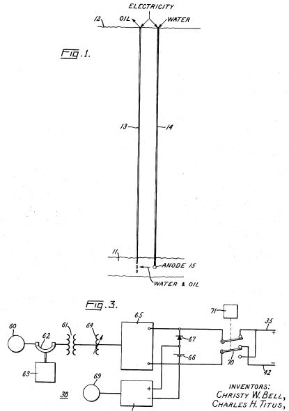
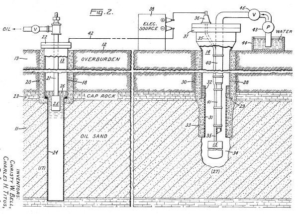
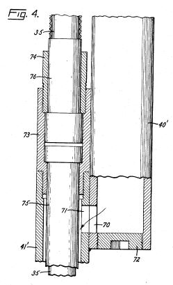
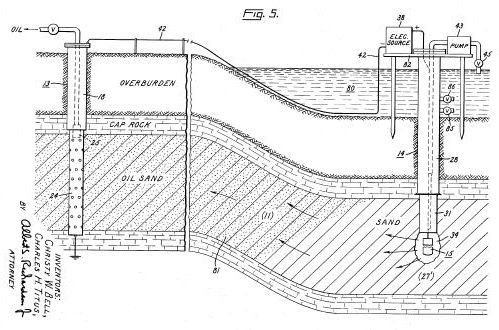
Referring now to FIG. 1, the reference number 11 represents a subterranean formation or earth stratum containing a reservoir or body of crude oil in a porous oil-bearing medium. Typically such oil bearing stratum formations are found beneath the upper strata of earth, referred to generally as overburden, at a depth of the order of 2,000 feet or more below the surface. Communication from the surface 12 to the formation 11 is established through spaced apart boreholes 13 and 14. The hole 13 comprises an oil-producing well, whereas the adjacent hole 14 can be a special hole designed for the transmission of water and electricity to the formation 11.
An anode 15 is lowered through the hole 14 to a medial elevation of the proximate region of stratum formation 11. The chamber or cavity in the oil sand where the anode is suspended is flooded with formation water which preferably is injected through the anode hole under fluid pressure in excess of that existing in the oil reservoir. In accordance with conventional practice, the casing in the hole 14 is sealed in the overburden above the formation 11, and the casing head is capped so that any desired pressure may be developed.
By means of an insulated cable in the anode hole 14, the relatively positive terminal of a high-voltage (at least 200 volts) d-c electric power source is connected to the anode 15. The negative terminal of the same source is connected to a ground electrode in the vicinity of the well 13, as to the metallic tubing in the producing well which thus constitutes a cathode. Between anode and cathode, the electrical resistance of the connate water in the oil sand is sufficiently low so that direct current can flow through this formation from the anode 15 to the lower regions of the producing well 13. The formation is heated conductively by electric current passing through it. It is believed that most of the voltage drop between the terminals of the d-c power source is concentrated near the electrodes. By utilizing an anode 15 of small surface area which extends vertically for only a small portion of the vertical height of the proximate formation 11 and raising the anode potential with respect to the cathode to a suitably high voltage, the temperature of the pressurized water that surrounds it can be raised to at least several hundred degrees Fahrenheit. Thus the water is heated and forced into the adjacent oil-bearing formation under the pressure developed in the anode hole. The water thus absorbed is induced to flow primarily toward the cathode well under the applied pressure and the augmenting directional force of electroosmosis.
In the foregoing manner, heat is efficiently imparted to the oil sand 11. This reduces the resistivity and the viscosity of the oil therein and tends to fluidize the same. The heated oil is entrained by the hot water and is forced under pressure toward the producing well, as is indicated in FIG. 1 by the pointer. As the pressure and heat fronts advance toward the producing well, the temperature is increased in regions of the sand more remote from the anode. Thus the entire reservoir of oil between the anode hole 14 and the producing well 13 is progressively heated, and the oil is forced into the producing well where it is removed by ordinary pumping means. The electrolytic action in the oil-bearing formation may tend to hydrogenate and thereby upgrade the oil that is removed therefrom. The operation of our process continues even after oil migrates away from the vicinity of the anode 15, and in fact the anode hole 14 can initially be drilled in an oil-dry region of the formation 11 beyond the contained body or reservoir of oil.
Suitable apparatus for practicing our invention is shown in FIG. 2, and its construction and operation will now be described. As is depicted in this figure, the borehole 13 comprises an oil producing well which penetrates one region 17 of the underground oil sand 11. The well 13 includes an elongated metallic casing 18 extending from the surface 12 to the cap rock 23 immediately above the region 17. The casing 18 is sealed in the overburden 19 by concrete 20 as shown, and its lower end is suitably joined to a perforated metallic liner 24 which continues through the bottom hole of the well and down to the underburden. A tubing string 21 is disposed inside the casing 18 where it extends from the casing head 22 to a pump 25 located in the liquid pool 26 that will accumulate inside the liner 24. Preferably the producing well 13 is drilled and constructed in accordance with common practices in the art, and it operates in the usual manner to withdraw or pump from the bottom hole 26 the mixture of oil and water that flows therein from the adjacent reservoir 11. Our invention is intended to stimulate the flow of that mixture into the producing well 13, thereby promoting the recovery of oil from the formation 11.
In accordance with our invention, another borehole 14 penetrates the oil sand 11 at a region 27 thereof horizontally-spaced from the region 17 with which the producing well 13 communicates. This borehole provides ingress to the region 27 for the anode 15 and for water. While a conventional producing well like the well 13 could be modified for this purpose, we have illustrated in FIG. 2 a borehole 14 comprising a special "anode hole" which will next be described.
The anode hole 14 includes an elongated metallic casing 28 whose lower end is terminated by a shoe 29 disposed at approximately the same elevation as the cap rock 23, and as usual this casing is sealed in the overburden 19 by concrete 30. Near the bottom of the hole a tubular liner 31 of insulating material extends from the casing 28 for an appreciable distance into the oil sand 11. The insulating liner 31 is telescopically joined to the casing 28 by a suitable tubular crossover means or coupler pipe 32. Preferably the space between the exterior wall of the liner 31 and the surrounding oil sand 11 is packed by high-temperature concrete 33. Although shown out of scale in FIG. 2 to simplify the drawing, actually, for reasons explained hereinafter, the liner 31 should have a substantial length and a relatively small inside diameter.
Below the liner 31, a cavity 34 is formed in the oil sand 11, and in this cavity there is an exposed, cylindrical electroconductive body comprising the anode 15 supported by a cable 35 which is insulated from ground. The anode 15 is relatively short compared to the depth of the proximate region of the oil sand (e.g., substantially less than one-half the depth of region 27), and it is positioned at an approximately medial elevation in this region. For example, if the region 27 were about 100 feet deep, the center of the anode would be disposed approximately 50 feet below the cap rock 23. (Obviously the vertical dimensions of the formation 11, the anode 15, and liner 31, and the cavity 34 have been foreshortened in FIG. 2 for the sake of drawing simplicity).
The anode 15 is attached to the lower end of the insulated cable 35 whoseother end emerges from a bushing or packing gland 36 in a cap 37 at the top of casing 28 and is connected to the positive pole (+) of an electric power source 38. Preferably the cable 35 is clamped for support at spaced intervals on a tubing string 40 which is disposed in the casing 28. The lower section 41 of this tubing string, which section extends axially through the liner 31, is made of insulating material whereby there is no metal in the zone between the anode 15 and the casing shoe 29 except for the conductor inside the insulated cable 35.
The negative pole (-) of the electric power source 38 is connected via a cable 42 to an uninsulated conductor or electrode in the producing well 13. As is shown in FIG. 2, the perforated liner 24 itself conveniently serves as this electrode (the cathode), and the well casing 18 provides a conductive path between the cathode and the cable 42. If desired a ground electrode other than the well casing but also in the vicinity of the well 13 may be used as cathode. More details of the electric power source 38 will be explained below in connection with the description of FIG. 3.
The tubing string 40, 41 in the anode hole 14 conveniently serves as a duct for delivering water from the surface 12 down the hole to the vicinity of the anode 15. Preferably a pump 43 at the surface is used to drive this water from a suitable reservoir 44 through a control valve 45 and into the upper section 40 of the tubing string. The injected water fills the cavity 34 where it is subjected to a high pressure (e.g., in the order of 1,000 p.s.i. or more) due to the hydrostatic head plus additional pressure externally imposed thereon by the pump 43, and it therefore can flow from the cavity into the surrounding region 27 of the oil sand 11. As is the case in known water flooding practice, the apparatus is arranged and operated so as to control the volume flow of water as desired.
The resistivity of the bottom hole water will be relatively low due to its saline content. While salts will probably diffuse therein from the adjacent formation 11, we presently prefer to inject electroconductive water from the surface. A slightly saline solution having a resistivity of approximately 1,000 ohm-centimeters or less is suitable for this purpose, it being understood that the degree of resistivity is not critical. In addition to being electroconductive, the injected water should have the proper mix of metal salts and other colloidal matter to make it compatible with the native formation 11. This will minimize or prevent swelling of certain clays which may be in the formation, thereby avoiding any severe reduction in permeability of the formation. In oil fields where natural formation water is readily available, it is preferable that such water be injected into the anode hole 14, thereby to minimize any disturbance to the chemical balance of the underground formation. Alternatively, surface water could be chemically treated to produce an equivalent hydrous electrolyte, i.e., a fluid of a composition having the essential characteristics (electroconduction and deflocculation properties) of the formation water. In either case, the injection water can also be treated if desired with chemical additives which have other beneficial affects such as enhancing oil production under the influence of the electric fields and current which will be present in the formation 11 between the anode 14 and the cathode 24.
From the foregoing it will be seen that a supply of formation water (or equivalent) is maintained about and in contact with the anode 14. Injecting the water from the surface, by a process of regulated flow (see below), ensures that the anode is continuously immersed in a pressurized pool of this fluid. The pool of fluid surrounding the anode constitutes an electroconductive path between this electrode and the adjacent oil sand. If necessary to prevent collapse of the walls of the cavity 34, the anode can also be surrounded by an inert porous medium such as glass beads or coarse sand having more than approximately 10 percent openings. A desirable alternative is to dispose both the anode 15 and the outlet of the water duct 41 inside a tubular container or basket having sidewalls of porous, insulating material, whereby a backflow of oil and sand is effectively prevented and the stream of injected water is directed over a substantial portion of the surface of the anode body before dispersing to the adjacent region 27 of the formation 11.
In practicing our improved method of stimulating oil recovery, an electric potential is applied to the anode 15 so as to raise its voltage, with respect to the remote region 17 of the formation 11 where the producing well 13 is located, to a relatively high level (i.e., of the order of several hundred to several thousand volts). Consequently current will flow through the formation 11 between the anode 15 and the producing well 13. The connate water in the intersticies of the oil sand initially provides a path for this current, and its temperature is raised thereby. Interstitial water typically constitutes only on the order of 15 percent of the formation 11 by volume, and the resistance of the conducting path through this formation will be much higher than that of the mass of saline water which immediately surrounds the anode 15 in the cavity 34. Nevertheless, because the current density in these conducting media is highest next to the relatively small surface area of the anode and decreases as an exponential function of the distance (radius) therefrom, a high percentage of the voltage drop between the anode and the ground is expected to be concentrated near the interface of the water mass and the adjoining oil-saturated region of the formation 11. As a result, a great deal of electric power dissipates in the vicinity of this interface, and the temperature of the pressurized water around the anode 15 will be raised appreciably. We contemplate a power input of the order of 25 to 1,000 kilowatts or more, which may heat the water in the cavity 34 to a temperature substantially in excess of 250 DEG Fahrenheit. This hot water is maintained in a liquid state by appropriately regulating both its temperature and its pressure. For example, the hydrostatic pressure of a 2,000 foot column of water exceeds 900 p.s.i., and at this pressure water remains liquid to approximately 530 DEG F.
It should be noted at this point that the vertical column of saline water above the cavity 34 will not form a short circuit between the anode 15 and the metallic casing 28 of the anode hole 14. This is because the water column is confined in a long, narrow space having a relatively small cross-sectional area. The dimensions of the insulating liner 31 through which the water is injected are selected so that the resistance of the confined water, if measured between the top of the anode 15 and the lower end of the casing 28, will be appreciably higher than the resistance of the conducting path through the oil sand between anode and cathode. Due to its close proximity to the source of heat, the bottom part of the insulating liner 31 is adventageously made of high-temperature material.
Within the underground formation 11, the temperature of the oil regionadjoining the pressurized hot water in the cavity 34 is elevated by this source of heat, whereby both the viscosity of the oil and the resistivity of the oil bearing sand are reduced. As hot oil recedes from the anode 15, more conductive saline water fills the vacated space in the porous media. The heat dissipated per unit volume of saline water will decrease near the anode where the resistivity of the water has decreased due to the temperature increase. Thus a heat front advances toward the cathode and behind it displaced oil is replaced by hot injected water. Because a substantial portion of the impressed unidirectional voltage appears at this advancing interface heat is continuously generated electrically in the immediate vicinity of the front to maintain the action.
In operation, our invention causes a stream of hot water and oil to flow in the formation 11 toward the producing well 13. This stream is driven by water injected into the anode hole 14, and it is guided toward the cathode by electro-osmosis. The latter effect can be attributed to a net movement of ions in the interstitial water under the influence of a unipolarity field. This electro-osmotic motive force supplements applied water pressure in the region between electrodes and promotes a migration of heating water from the cavity 34 through the porous oil sand to the producing well 13. In a given medium the volume flow of water due to electro-osmosis depends on the magnitude of current being conducted. Because the sand particles in the native formation 11 are predominantly water wet and because the residual oil tends to adhere, by interfacial tension, to the contiguous water film on these particles, this electro-osmotic mode of transporting water through the capillaries and crevices of the oil sand is particularly effective in achieving the desired result of transferring heat and motion to the residual oil.
Some of the electric energy supplied to the electrodes in our invention will be utilized to liberate hydrogen from the water in the pool 26 at the bottom of the producing well 13. This electro-chemical action is well known as electrolysis. Because the formation 11 is not homogeneous, there are anomalies in its conductivity that form a series of local anodes and cathodes between the main electrodes 15 and 24. Consequently, hydrogen and other gases will be electrolytically released throughout the formation. Some of the gasses, such as chlorine, will chemically react to form certain beneficial acids which promote formation of appropriate porosity and fluid flow in the oil sand. The union of hydrogen and warm oil may partially hydrogenate the oil that is extracted from the formation 11 thereby improving the grade and the value of the recovered oil. Furthermore, the unipolarity electric field between the main electrodes may raise the peak kinetic energy of mobile charged particles in some areas of the underground formation to a sufficiently high level to produce fractional distillation and further upgrading of the oil in situ. Gasses thus liberated and not absorbed or reacted may accumulate in higher strata and develop pressure which supplements other forces driving oil toward the well 13.
In the cavity 34 electrolytic action contributes to a hostile environment for the anode 15 and associated parts of the apparatus disposed at the bottom of the anode hole. In operation oxygen and other corrosive gases and chemicals are liberated at the anode. Electrolytic action will tend to deplate or consume certain positively energized metals. Therefore care should be exercised in designing the anode 15 so that its surface, which is the only exposed conductor in the bottom of the anode hole 14, will resist both chemical and galvanic corrosion.
To ensure a sound mechanical and electrical connection between the cable 35 and the anode 15 under the foregoing difficult conditions and in the high-pressure ambient at the contemplated depth of the anode hole, it is believed desirable that the cable be inserted, as by a threaded conducting plug connection, into a recess in the anode. The lower section of the cable and the juncture of the plug and the anode should then be covered with insulation which has adequate dielectric strength and is impervious to oxygen and other deleterious chemicals. There is a possibility that a high pressure differential between the exterior surface and the interior recess of the anode may damage the anode. To protect the interior surface of the anode it is desirable to fill any voids in the anode recess with suitable high gravity electroconductive liquid and to close the recess with a pressure-equalizing seal. The exterior surface of the anode body should be the only part of the apparatus from which current enters the surrounding saline water, and it is resistant to chemical attack and deplating.
An electric power supply suitable for energizing the anode 15 has been shown in FIG. 3. The availability of three-phase a-c high-voltage service is assumed, and in FIG. 3 this service is illustrated symbolically at 60. The high voltage is fed to the primary windings of a power transformer 61 through a conventional circuit breaker 62 which is equipped with an operating mechanism 63 for opening and closing the primary circuit on command. The secondary circuit of the power transformer 61 is connected to a controlled converter which is constructed and arranged to apply across the conductors 35 and 42 a unipolarity output voltage of controllable magnitude. The illustrated converter comprises an adjustable autotransformer 64 in series with a high-power rectifier 65. The average magnitude of its output voltage can be varied from a few hundred volts to thousands of volts. This can be done manually or, if desired, automatically by suitable means well known in the pertinent electrical art.
In operation, the load on the power supply 38 is expected to vary after the anode 15 is first energized. The resistivity of the saline water tends to decrease with increasing temperature in the formation 11. The presently preferred mode of controlling the electric power and water inputs of our process will now be explained. The magnitude of current in the cable 35 is regulated by suitably adjusting or programming the applied voltage. In this way the electric current between anode and cathode can be held at a desirable preset level. To prevent excessive heating of the anode itself, the electroconductive fluid supplied through the anode hole 14 is suitably controlled so as to vary the value of its volume rate of flow as a function of the electric energy dissipated underground. This can be accomplished, for example, by employing appropriate means for controlling the rate of flow of the injected fluid in accordance with the product of the magnitude of applied voltage and the magnitude of anode-to-cathode current, whereby the desired rate of fluid flow is determined by the amount of input power. As the input power increases, so does the quantity of injected fluid thereby beneficially increasing the cooling effect on the anode 15. A maximum pressure override should also be provided to prevent excessive underground pressure which might fracture the formation 11.
For optimum utilization of the input power without excessive heating, it may be desirable to open the circuit breaker 62 for a certain interval or intervals of time during which oil can continue flowing in the oil-bearing formation due to the energy retained therein. If and when the primary circuit is deenergized, a low-voltage (e.g., 12 volts) positive bias is preferably maintained on the anode 15 to minimize adverse galvanic action in the anode hole, and toward this end a battery 66 is connected in series with an isolating diode 67 across the output terminals of the rectifier 65. To recharge the battery 67, it is connected to a conventional battery charger 68 which is coupled to a suitable source 69. This positive bias means, which is not our joint invention, is more fully described and is claimed by C.H. Titus and H.N. Schneider in a copending patent application Ser. No. 117,488 filed on Feb. 22, 1971 assigned to the assignee of the present invention.
It may be advantageous to reverse from time to time the unipolarity voltage applied between the cables 35 and 42. Toward this end, suitable reversing means is optionally provided. By way of example, FIG. 3 shows a polarity reversing switch 70 between the rectifier 65 and the cables, with the position of this switch being controlled as desired by an associated mechanism 71. Ordinarily the reversing cycle would be asymmetrical so that there is a net electroosmotic movement of water through the oil sand in the direction of the producing well 13. The reactance of the cable 35 in the anode hole 14 will not seriously impede the flow of current through this path so long as either direct current or low-frequency reversible current is being supplied. In view of these alternative modes of practicing our invention, the terms "d-c" and "unipolarity" are meant herein to apply to quantities whose direction of influence can be reversed during or after a cycle of operation of our process without reducing to zero the average influence of the quantity in that direction during that cycle.
When our process is operated in either the discontinuous power mode or the reverse polarity mode described in the preceding two paragraphs, respectively, it is possible to use the anode hole as a producing well for extracting oil from the proximate region 27 of the formation 11. Furthermore, it is possible to use our invention to recover oil from a subterranean formation in a push-pull fashion where there is only a single borehole communicating with the surface of the ground.
FIG. 4 shows an alternative arrangement for joining the two sections 40 and 41 of the tubing string in the anode hole 14. In FIG. 4 the lowest part of the upper section 40' of the tubing string is secured in side-by-side relation to the top part 41' of the lower section, and these parts are respectively provided with registering slots 70 and 71 which permit the injected water to flow from the section 40' into part 41'. The bottom of section 40' is closed by a suitable plug 72 as shown. The top of part 41' is provided with a packing gland for admitting the cable 35. As is shown in FIG. 4, this gland includes cooperating threaded sleeves 73 and 74 between which the shoulders of a pair of tubular metal clamps 75 and 76 are captured. The insulated cable 35 passes vertically through this assembly, and its lower portion is therefore disposed inside the lower section of the tubing string. At an elevation below what is shown in the fragmentary view of FIG. 4, the metal part 41' is connected to an insulating tube, and the metal clamp 75 is terminated. There are two principal advantages of this "Zee" assembly. It protects the cable 35 from damage during installation of the anode 15, and it directs the injected water around the lower portion of the cable 35 and directly over the top of the anode 15 for improved cooling of the surfaces of these conductors. The Zee assembly is more fully described and is claimed by C.H. Titus and H. N. Schneider in U.S. Pat. No. 3,674,912 filed Feb. 22, 1971 and assigned to the same assignee as is the present application.
At FIG. 5 we have illustrated schematically a modified form of apparatus whereby our invention may be practiced in a particular embodiment made available when all or a portion of the reservoir of oil in an oil bearing formation lies under a body of water, and in particular under saline water, as offshore under the sea. In the embodiment there illustrated the earth structure including an oil bearing formation 11 is shown in substantially the same manner as at FIG. 2 except that part of stratum formation 11 lies under a body of seawater 80. At FIG. 5 the anode hole 14 is located in a region 27' of the stratum formation 11 which is laterally contiguous to but beyond the body or reservoir of oil 81 contained in the formation and below an off-shore area of the earth's surface. The electric power source 38 and pump 43 associated with the anode hole are mounted on a sea platform 82 and the anode hole casing 28 extends to the platform.
The water inlet to the pump 43 is shown connected to the seawater 80 as a supply reservoir, but it will be understood that other appropriate sources of water for injection may be used, as described heretofore. If seawater is used it may require certain chemical additives of the type previously mentioned, but due to its accessibility to an offshore anode hole it is to be preferred. Use of seawater in an offshore anode region offers the further advantage that hydrostatic pressure of the sea itself may be used in place of the pump 43 to supply the added pressure required to inject water at the anode cavity. To illustrate such a water supply source we have shown two water inlet valves 85 and 86 located on the anode casing 14 at different depths beneath the surface of the sea 80. A selected one of these valves may be opened (with the pump shut down) to admit sea water at a desired pressure to the anode cavity. Any desired number of such inlet valves may be provided at different pressure levels.
The producing well 13 at FIG. 5 is shown in an onshore location with metal liner 24 electrically connected to ground and through a cable 42 to the negative terminal of the d-c supply source 38, as at FIG. 2. While this well is shown as penetrating the oil body 81, it will now be understood that if desired it may be located initially beyond the body of oil 81 between the electrodes.
In summary it will be seen that we have marshalled a number of different forces toward the desired end of efficiently utilizing bulk electric power to increase the amount and the value of oil extracted from underground reservoirs. While most useful in combination, all of these forces do not necessarily have to be employed in concert to obtain satisfactory results.
In spite of the high potential contemplated at the anode 15, the voltage gradient near the surface 12 of the ground will be small or negligible. Therefore our invention can be practiced safely. Where necessary, conventional cathodic protection can be used to retard corrosion of underground pipe lines, if any, in the vicinity of the surface.
US2014116683
Method
for Increasing Bottom-Hole Formation Zone Permeability
RU2132757
Method of Removing Hydrocarbons from Soil
KR20010086551
Purification Method of Contaminated Soil with Petroleum Oil
RU2602615
Method of Soil Cleaning from Hydrocarbons
KR101464878
Remediation System for Multi-Contaminated Soils
An aspect of the present invention provides a remediation system for complexly contaminated soil using a combined chemical oxidation and soil flushing method by electrokinetic remediation that increases the remediation efficiency of complexly contaminated soil as a treatment region is formed by hydrogen peroxide inserted into one side of a soil cell from an anode cell to induce the oxidation and decomposition of oil contaminants and the oil contaminants are oxidized and decomposed by being flushed and adsorbed by an anionic surface active agent inserted into the other side of the soil cell from a cathode cell to be moved into the treatment region. The remediation system for complexly contaminated soil using a combined chemical oxidation and soil flushing method by electrokinetic remediation according to an embodiment of the present invention comprises: a soil cell complexly contaminated by oil contaminants and heavy metal contaminants; an anode cell having an anode inserted into one side of the soil cell; a cathode cell having a cathode inserted into the other side of the soil cell to be separated from the anode by a certain distance; a hydrogen peroxide supply cell connected to the anode cell to supply hydrogen peroxide to one side of the soil cell; a first anionic surface active agent supply cell connected to the cathode cell to supply a first anionic surface active agent to the other side of the soil cell; and a power supply device for flushing and adsorbing oil contaminants via electric ion movement using the first anionic surface active agent to be moved from the cathode to the treatment region while simultaneously forming the treatment region, which is defined by the flowing distance of hydrogen peroxide, so that oil contaminants can be oxidized and decomposed as hydrogen peroxide is moved from the anode to the cathode via electroosmosis by supplying power to the anode and the cathode.
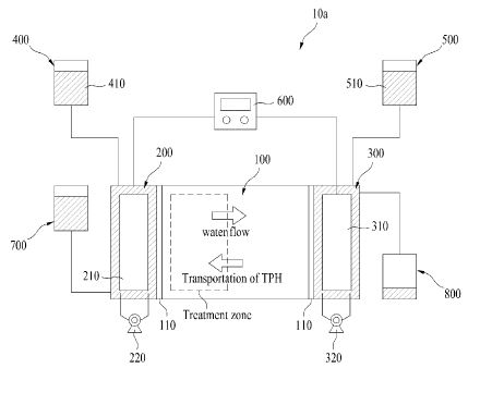
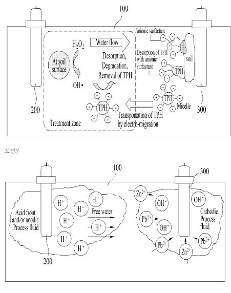
US4645004
Electro-Osmotic Production of Hydrocarbons Utilizing Conduction Heating of Hydrocarbon Formations
BACKGROUND OF THE INVENTION
This invention relates generally to the exploitation of hydrocarbon-bearing formations having substantial electrical conductivity, such as tar sands and heavy oil deposits, by the application of electrical energy to heat the deposits. More specifically, the invention relates to the delivery of electrical power to a conductive formation at relatively low frequency or d.c., which power is applied between rows of elongated electrodes forming a waveguide structure bounding a particular volume of the formation, while at the same time the temperature of the electrodes is controlled.
Materials such as tar sands and heavy oil deposits are amenable to heat processing to produce gases and hydrocarbons. Generally the heat develops the porosity, permeability and/or mobility necessary for recovery. Some hydrocarbonaceous materials may be recovered upon pyrolysis or distillation, others simply upon heating to increase mobility.
Materials such as tar sands and heavy oil deposits are heterogeneous dielectrics. Such dielectric media exhibit very large values of conductivity, relative dielectric constant, and loss tangents at low temperature, but at high temperatures exhibit lower values for these parameters. Such behavior arises because in such media ionic conducting paths or layers are established in the moisture contained in the interstitial spaces in the porous, relatively low dielectric constant and loss tangent rock matrix. Upon heating, the moisture evaporates, which radically reduces the bulk conductivity, relative dielectric constant, and loss tangent to essentially that of the rock matrix.
It has been known to heat electrically relatively large volumes of hydrocarbonaceous formations in situ. Bridges and Taflove U.S. Pat. No. Re. 30,738 discloses a system and method for such in situ heat processing of hydrocarbonaceous earth formations wherein a plurality of elongated electrodes are inserted in formations and bound a particular volume of a formation of interest. As used therein, the term "bounding a particular formation" means that the volume is enclosed on at least two sides thereof. The enclosed sides are enclosed in an electrical sense with a row of discrete electrodes forming a particular side. Electrical excitation between rows of such electrodes established electrical fields in the volume. As disclosed in such patent, the frequency of the excitation was selected as a function of the bounded volume so as to establish a substantially nonradiating electric field which was confined substantially in the volume. The method and system of the reissue patent have particular application in the radio-frequency heating of moderately lossy dielectric formations at relatively high frequency. However, it is also useful in relatively lossy dielectric formations where relatively low frequency electrical power is utilized for heating largely by conduction. The present invention is directed toward the improvement of such method and system for such heating of relatively conductive formations at relatively low frequency and to the application of such system for heating with d.c.
SUMMARY OF THE INVENTION
For electrically heating conductive formations, it is desirable to utilize relatively low frequency electrical power or d.c. to achieve relatively uniform heating distribution along the line. At low frequency, it is necessary that conductive paths remain conductive between the subsurface electrodes and the formation being heated. It is also desirable to heat the formation as fast as possible in order to minimize heat outflow to barren regions. This presents certain inconsistent requirements, as fast heating requires a large amount of heat at the electrodes, and the resultant high temperatures boil away the water needed to maintain the conductive paths. On the other hand, if the heating proceeds slowly, excessive temperatures leading to vaporization of water and consequent loss of conductivity are avoided, but there is economically wasteful loss of heat to the barren formations in the extended time needed to heat the deposit of interest.
It is a primary aspect of the present invention to provide compromises to best meet such disparate requirements in the in situ heating of earth formations having substantial conductivity. A waveguide structure as shown in the reissue patent is emplanted in the earth to bound a particular volume of an earth formation with a waveguide structure formed of respective rows of discrete elongated electrodes wherein the spacing between rows is greater than the distance between electrodes in a respective row and in the case of vertical electrodes substantially less than the thickness of the hydrocarbonaceous earth formation. Electrical power at no more than a relatively low frequency is applied between respective rows of the electrodes to deliver power to the formation while producing relatively uniform heating thereof and limiting the relative loss of heat to adjacent barren regions to less than a tolerable amount. At the same time the temperature of the electrodes is controlled near the vaporization point of water thereat to maintain an electrically conductive path between the electrodes and the formation. A d.c. polarized potential is applied to enhance flow of reservoir fluid toward at least one preselected electrode.
A waveguide electrical array which employs a limited number of small diameter electrodes would be less expensive to install than an array using more electrodes but would result in excess electrode temperature and nonuniform heating and consequently inefficient use of electrical power. On the other hand, a dense array, that is, one in which the spacing s between rows is greater than the distance d between electrodes in a row, would be somewhat more costly, but would heat more uniformly and more rapidly and, therefore, be more energy efficient.
A key to optimizing these conflicting factors is to control the temperature of the electrodes and the resource immediately adjacent the electrodes by properly selecting the deposit gas pressure, heating rates, heating time, final temperature, electrode geometry and positioning and/or cooling the electrodes.
These and other aspects and advantages of the present invention will become more apparent from the following detailed description, particularly when taken in conjunction with the accompanying drawings.
BRIEF DESCRIPTION OF THE DRAWINGS
FIG. 1 is a vertical sectional view, partly diagrammatic, of a preferred embodiment of a system for the conductive heating of an earth formation in accordance with the present invention, wherein an array of electrodes is emplaced vertically, the section being taken transversely of the rows of electrodes;
FIG. 2 is a diagrammatic plan view of the system shown in FIG. 1;
FIG. 3 is an enlarged vertical sectional view, partly diagrammatic, of part of the system shown in FIG. 1;
FIG. 4 is a vertical sectional view, partly diagrammatic, of an alternative system for the conductive heating of an earth formation in accordance with the present invention, wherein an array of electrodes is emplaced horizontally, the section being taken longitudinally of the electrodes;
FIG. 5 is a vertical sectional view, partly diagrammatic of the system shown in FIG. 4, taken along line 5--5 of FIG. 4;
FIG. 6 is a vertical sectional view comparable to that of FIG. 4 showing an alternative system with horizontal electrodes fed from both ends;
FIG. 7 is a plan view, mostly diagrammatic, of an alternative system comparable to that shown in FIG. 3, with cool walls adjacent electrodes;
FIG. 8 is a vertical sectional view, partly diagrammatic of the system shown in FIG. 7, taken along line 8--8 of FIG. 7;
FIG. 9 is a set of curves showing the relationship between a time dependent factor c and heat loss and a function of deposit temperature utilizing the present invention;
FIG. 10 is a set of curves showing the temperature distribution at different heating rates when heat is delivered to a defined volume;
FIG. 11 is a set of curves showing the relationship between time and temperature at different points when a formation is heated by a sparse array;
FIG. 12 is a set of curves showing the relationship between time and temperature at different points when a formation is heated in accordance with the present invention with electrode diameters of 32 inches; and
FIG. 13 is a set of curves showing the relationship of time and temperature at the same points as in FIG. 12 in accordance with the present invention with electrode diameters of 14 inches.
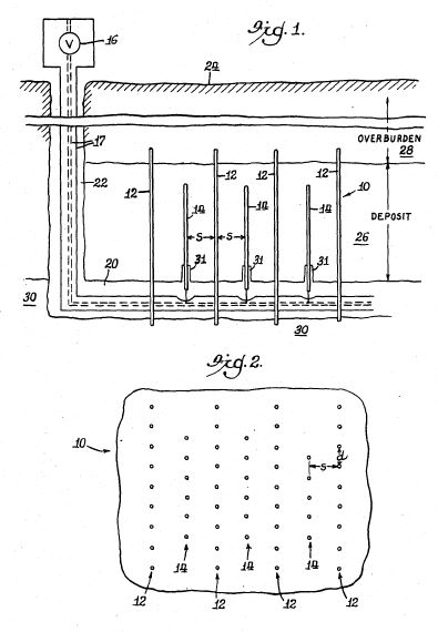
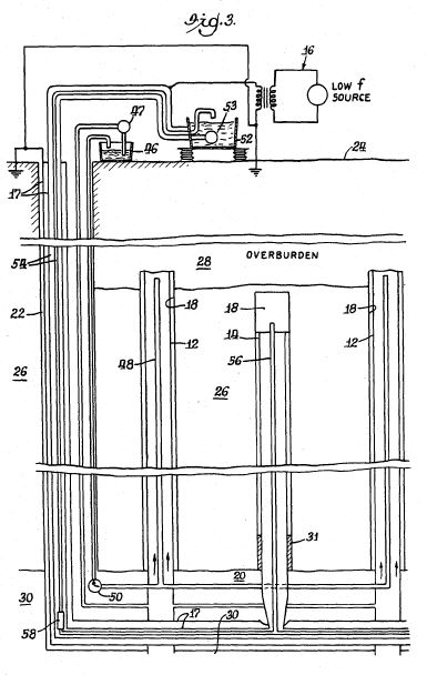
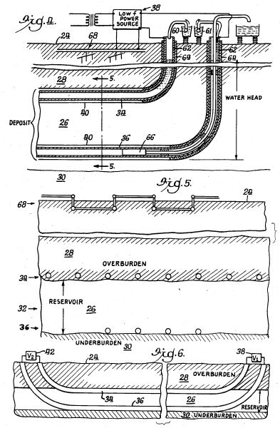
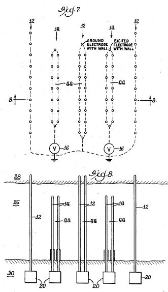
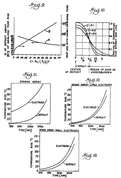
DETAILED DESCRIPTIONS OF THE PREFERRED EMBODIMENTS
FIGS. 1, 2 and 3 illustrate a system for heating conductive formations utilizing an array 10 of vertical electrodes 12, 14, the electrodes 12 being grounded, and the electrodes 14 being energized by a low frequency or d.c. source 16 of electrical power by means of a coaxial line 17. The electrodes 12, 14 are disposed in respective parallel rows spaced a spacing s apart with the electrodes spaced apart a distance d in the respective rows. The electrode array 10 is a dense array, meaning that the spacing s between rows is greater than the distance d between electrodes in a row. The rows of electrodes 12 are longer than the rows of electrodes 14 to confine the electric fields and consequent heating at the ends of the rows of electrodes 14.
The electrodes 12, 14 are tubular electrodes emplaced in respective boreholes 18. The electrodes may be emplaced from a mined drift 20 accessed through a shaft 22 from the surface 24 of the earth. The electrodes 12 preferably extend, as shown, through a deposit 26 or earth formation containing the hydrocarbons to be produced. The electrodes 12 extend into the overburden 28 above the deposit 26 and into the underburden 30 below the deposit 26. The electrodes 14, on the other hand, are shorter than the electrodes 12 and extend only part way through the deposit 26, short of the overburden 28 and underburden 30. In order to avoid heating the underburden and to provide the power connection, the lower portions of the electrodes 14 may be insulated from the formations by insulators 31, which may be air. The effective lengths of the electrodes 14 therefore end at the insulators 31.
FIGS. 4 and 5 illustrate a system for heating conductive formations utilizing an array 32 of horizontal electrodes 34, 36 disposed in vertically spaced parallel rows, the electrodes 34 being in the upper row and the electrodes 36 in the lower row. The upper electrodes 34 are preferably grounded, and the lower electrodes 36 are energized by a low frequency or d.c. source 38 of electrical power. The electrodes 34, 36 are disposed in parallel rows spaced apart a spacing s, with the electrodes spaced apart a distance d in the respective rows. The electrode array 32 is also a dense array. The upper row of electrodes 34 is longer than the lower row of electrodes 36 to confine the electric fields from the electrodes 36. The electrodes 34 extend beyond both ends of the electrodes 36 for the same reason. Grounding the upper electrodes 34 keeps down stray fields at the surface 24 of the earth.
The electrodes 34, 36 are tubular electrodes emplaced in respective boreholes 40 which may be drilled by well known directional drilling techniques to provide horizontal boreholes at the top and bottom of the deposit 26 between the overburden 28 and the underburden 30. Preferably the upper boreholes are at the interface between the deposit 26 and the overburden 28, and the lower boreholes are slightly above the interface between the deposit 26 and the underburden 30.
FIG. 6 illustrates a system comparable to that shown in FIGS. 4 and 5 wherein the array is fed from both ends, a second power source 42 being connected at the end remote from the power source 38.
FIGS. 7 and 8 illustrate a system comparable to that of FIGS. 1, 2 and 3 with an array of vertical electrodes. In this system the rows of like electrodes 12, 14 are in spaced pairs to provide a low field region 44 therebetween that is not directly heated to any great extent.
The deposit thickness h and the average or effective thermal diffusion properties determine the uniformity of the temperature distribution as a function of heating time t and can be generally described for any thickness of a deposit in the terms of a deposit temperature profile factor c, such that
c=kt/(h/2)@2
where k is the thermal diffusivity. FIG. 9 presents a curve A showing the relationship between the factor c and the portion of a deposit above 80% of the temperature rise of the center of the deposit for a uniform heating rate through the heated volume. Note that at c=0.1, about 75% of the heated volume has a temperature rise greater than 80% of the temperature rise of the center of the heated volume.
FIG. 10 illustrates the heating profiles for three values of the factor c as a function of the distance from the center of the heated volume, the fraction of the temperature rise that would have been reached in the heated volume in the absence of heat outflow. Note that where c=0.1 or c=0.2, the total percentage of heat lost to adjacent formations is relatively small, about 10% to 15%. Where low final temperatures, e.g., less than 100 DEG C., are suitable, c up to 0.3 can be accepted, as the heat lost, or extra heat needed to maintain the final temperature, is, while significant, economically acceptable. FIG. 9, curve B, showing percent heat loss as a function of the factor c, shows percent heat loss to be less than 25% at c=0.3. On the other hand, if higher temperatures (e.g., about 200 DEG C.) are desired to crack the bitumen, then higher central deposit temperatures above the design minimum are needed to process more of the deposit, especially if longer heating times are employed. Moreover, the heat outflows at these higher temperatures are more economically disadvantageous. Thus a temperature profile factor of c less than about 0.15 is required. In general the heating rate should be great enough that c is less than 30 times the inverse of the ultimate increase in temperature AT in degrees celsius of the volume:
c.ltoreq.0.3(100/.DELTA.T)
The lowest values of c are controlled more by the excess temperature of electrodes and are discussed below.
The electrode spacing distance d and diameter a are determined by the maximum allowable electrode temperature plus some excess if some local vaporization of the electrolyte and connate water can be tolerated. In a reasonably dense array, the hot regions around the electrodes are confined to the immediate vicinity of the electrodes. On the other hand, in a sparse array, where s is no greater than d, the excess heat zone comprises a major portion of the deposit.
FIG. 11 illustrates a grossly excessive heat build-up on the electrodes as compared to the center of the deposit for a sparse array. In this example row spacing s was 10 m, electrode spacing d 10 m, electrode diameter a 0.8 m, and thermal diffusivity 10@-6 m@2 /s, with no fluid flow.
FIG. 12 shows how the electrode temperature can be reduced by the use of a dense array. In this example row spacing s was 10 m, electrode spacing d 4 m, electrode diameter a 0.8 m, and thermal diffusivity 10@-6 m@2 /s, with no fluid flow.
FIG. 13 illustrates the effect of decreasing the diameter of the electrodes of the dense array of FIG. 12 such that the temperature of the electrode is increased somewhat more relative to the main deposit. In this example row spacing s was 10 m, electrode spacing d 4 m, electrode diameter a 0.35 m, and thermal diffusivity 10@-6 m@2 /s, with no fluid flow. The region of increased temperature is confined to the immediate vicinity of the electrode and does not constitute a major energy waste. Thus, varying the electrode separation distance d and the diameter of the electrode a permit controlling the temperature of the electrode either to prevent vaporization or excessive vaporization of the electrolyte in the borehole and connate water in the formations immediately adjacent the electrode.
The electrode spacing d and diameter a are chosen so that either electrodetemperature is comparable to the vaporization temperature, or if some local vaporization is tolerable (as for a moderately dense array), the unmodified electrode temperature rise without vapor cooling will not significantly exceed the vaporization temperature.
The means for providing water for both vaporization and for maintenance of electrical conduction is shown in the drawings, particularly in FIG. 3 for vertical electrodes and in FIG. 4 for horizontal electrodes. As shown in FIG. 3, a reservoir 46 of aqueous electrolyte provides a conductive solution that may be pumped by a flow regulator and pump 47 down the shaft 22 and up the interior of the electrodes 12 and into the spaces between the electrodes 12 and the formation 26. A vapor relief pipe 48, together with a pressure regulator and pump 50 returns excess electrolyte to the reservoir 46 and assures that the electrolyte always covers the electrodes 12. Similarly, a reservoir 52 provides such electrolyte down the shaft 22, whence it is driven by a pressure regulator and pump 53 up the interior of the electrodes 14 and into the spaces between the electrodes 14 and the formation 26. In this case the electrodes are energized and not at ground potential. The conduits 54 carrying the electrolyte through the shaft 22 are therefore at the potential of the power supply and must be insulated from ground, as is the reservoir 52. The conduits 54 are therefore in the central conductor of the coaxial line 17. The electrodes 14 have corresponding vapor relief pipes 56 and a related pressure regulator and pump 58.
As shown in FIG. 4, electrolyte is provided as needed from reservoirs 60, 61 to the interior tubing 62 which also acts to connect the power source 38 to the respective electrodes 34, 36, the tubing being insulated from the overburden 28 and the deposit 26 by insulation 64. The electrolyte goes down the tubing 62 to keep the spaces between the respective electrodes 34, 36 and the deposit 26 full of conductive solution during heating. The tubing to the lower electrode 36 may later be used to pump out the oil entering the lower electrode, using a positive displacement pump 66.
In either system, the electrolyte acts as a heat sink to assure cool electrodes and maintain conductive paths between the respective electrodes and the deposit. The water in the electrolyte may boil and thereby absorb heat to cool the electrodes, as the water is replenished.
The vaporization temperature is controlled by the maximum sustainable pressure of the deposit. Typically for shallow to moderate depth deposits the gauge pressure can range from a few psig to 300 psig with a maximum of about 1300 psig for practical systems. The tightness of adjacent formations also influences the maximum sustainable vapor pressure. In some cases, injection of inert gases to assist in maintaining deposit pressure may be needed.
Another way to keep the electrodes cool is to position the electrodes adjacent a reduced field region on one side of an active electrode row. This reduces radically the heating rate in the region of the diminished field, thus creating in effect a heat sink which radically reduces the temperature of the electrodes, in the limiting case to about half the temperature rise of the center portion of the deposit.
As shown in FIGS. 7 and 8, in the case of vertical arrays, pairs of electrodes 12, 14 can be installed from the same drift and the same potential is applied to each pair, thus the regions 44 between the pairs become low field regions. By proper selection of heating rates and pair separation, it is possible to control the temperature of the electrode at slightly below that for the center of the deposit. The thickness of the cool wall region 44 can be sufficiently thin that the cool wall region can achieve about 90% of the maximum deposit temperature via thermal diffusion from the heated volume after the application of power has ended.
As shown in FIGS. 4, 5 and 6 in the case of a horizontally enlarged biplate, a nearly zero field region exists on the barren side of the row of grounded upper electrodes 34 and a nearly zero field region exists on the barren side of the row of energized electrodes 36. Such low field regions act as the regions 44 in the system shown in FIGS. 7 and 8.
The arrangement of FIGS. 4, 5 and 6 with the upper electrodes grounded is superior to other arrangements of horizontal electrodes in respect to safety. No matter how the biplate rows are energized and grounded (such as upper electrode energized and lower electrode grounded, vice versa or both symmetrically driven in respect to ground) leakage currents will flow near the surface 24 that may be small but significant in respect to safety and equipment protection. These currents will create field gradients which, although small, can be sufficient to develop hazardous potentials on surface or near-surface objects 68, such as pipelines, fences and other long metallic structures, or may destroy operation of above-ground electrical equipment. To mitigate such effects, ground mats can be employed near metallic structures to assure zero potential drops between any metallic structures likely to be touched by anyone.
These safety ground mats as well as electrical system grounds will collect the stray current from the biplate array. These grounds then serve in effect as additional ground electrodes of a line. Leakage currents between the grounding apparatus at the surface and the biplate array also heat the overburden, especially if the uppermost row is excited and the deposit is shallow. Thus biplate arrays, although having two sets of electrodes of large areal extent, also implicitly contain a third but smaller set of electrodes 68 near the surface at ground potential. Although this third set of electrodes collects diminished currents, the design considerations previously discussed to prevent vaporization of water in the earth adjacent the other electrodes must also be applied.
The near surface ground currents are minimized if the upper electrodes 34 are grounded and the lower electrodes 36 are energized. Also the grounded upper electrodes 34 can be extended in length and width to provide added shielding. This requires placing product collection apparatus at the potential of the energized lower set of electrodes by means of isolation insulation. However, this arrangement reduces leakage energy losses as compared to other electrodes energizing arrangements. Such leakage currents tend to heat the overburden 28 between the row of upper electrodes 34 and the above-ground system 68, giving rise to unnecessary heat losses.
Short heating times stress the equipment, and therefore, the longest heating times consistent with reasonable heat losses are desirable. This is especially true for the horizontal biplate array. The conductors of an array in the biplate configuration, especially if it is fairly long, will inject or collect considerable current. The amount of current at the feed point will be proportional to the product of the conductor length l, the distance d between electrodes within the row, and the current density J needed to heat the deposit to the required temperature in time t. Thus the current I per conductor becomes at the feed point (assuming small attenuation along the line):
I=(J) (l) (d) ##EQU1## where
.sigma. is the conductivity of the reservoir and joules-to-heat is the energy required to heat a cubic meter to the desired temperature. Thus the current carrying requirement of the conductors at the feed points is reduced by increasing the heat up time t as determined by the maximum allowable temperature profile factor c and deposit thickness h. Further, making the array more dense, that is, decreasing d, also reduces the current carrying requirements as well as decreasing l. If conductor current at the feed point is excessive, heat will be generated in the electrode due to I@2 R losses along the conductor. The power dissipated in the electrode due to I@2 R losses can significantly exceed the power dissipated in the reservoir immediately adjacent the electrode. This can cause excessive heating of the electrode in addition to the excess heat generated in the adjacent formation due to the concentration of current near the electrode. Thus another criterion is that the I@2 R conductor losses not be excessive compared to the power dissipated in the media due to narrowing of the current flow paths into the electrodes. Also the total collected current should not exceed the current carrying rating of the cable feed systems.
Another cause of excess temperature of the electrodes over that for the deposit arises from fringing fields near the sides of the row of excited electrodes. Here the outermost electrodes (in a direction transverse to the electrode axis) carry additional charges and currents associated with the fringing fields. As a consequence, both the adjacent reservoir dissipation and I@2 R longitudinal conductor losses will be significantly increased over those experienced for electrodes more centrally located. To control the temperature of these outermost electrodes, several methods can be used, including: (1) increasing the density of the array in the outermost regions, (2) relying on additional vaporization to cool these electrodes, and (3) the enlarging the diameter of these electrodes. Some cooling benefit will also exist for the cool-wall approach, especially in the case of the vertical electrode arrays if an additional portion of the deposit can be included in the reduced field region near the outermost electrodes. Applying progressively smaller potentials as the outermost electrodes are neared is another option.
In the case of the biplate array, especially if it extends a great length into the deposit, such as over 100 m, special attention must be given to the path losses along the line. To alleviate the effects of such attenuation, the line may be fed from both ends, as shown in FIG. 6. At the higher frequencies, these are frequency dependent and are reduced as the frequency is decreased. Perhaps not appreciated in earlier work, is that there is a limit to how much the path attenuation can be reduced by lowering the frequency. The problem is aggravated because, as the deposit is heated, it becomes more conducting.
A buried biplate array or triplate array exhibits a path loss attenuation .alpha. of
.alpha.=8.7[(R+j.omega.L)(G+j.omega.C)]@1/2 dB/m
where
R is the series resistance per meter of the buried line, which includes an added resistance contribution from skin effects in the conductor, if present,
L is the series inductance per meter of the buried line,
G is the shunt conductance over a meter for the line and is directly proportional to .sigma., the conductivity of the deposit,
C is the shunt capacitance over a meter for the line. Where conduction currents dominate, G>>j.omega.c, so that the attenuation .alpha. becomes
.alpha.=8.7[(R+j.omega.L)(G)]@1/2 dB/m
If the frequency .omega. is reduced, j.omega.L is radically reduced, R is partially decreased (owing to a reduction in skin effect loss contribution) and G tends to remain more or less constant. Eventually, as frequency .omega. is decreased, R>>j.omega.L, usually at a near zero frequency condition, so that
.alpha.=8.7[(R)(G)]@1/2 dB/m
If thin wall steel is used as the electrode material, unacceptable attenuation over fairly long path lengths could occur, especially at the higher temperatures where conductance G and conductivity .sigma. are greater. If thin walled copper or aluminum is used for electrodes (these may be clad with steel to resist corrosion), the near zero-frequency attenuation can be acceptably reduced so that
.alpha.l=8.7[(R)(G)]@1/2 (l).ltoreq.2dB
for the single end feed of FIG. 4 and less than 8 dB for the double end feed of FIG. 6.
When d.c. power is applied, advantage may be taken of electro-osmosis to promote the production of liquid hydrocarbons. In the case of electro-osmosis, water and accompanying oil drops are usually attracted to the negative electrodes. The factors affecting electro-osmosis are determined in part by the zeta potentials of the formation rock, and in some limited cases the zeta potentials may be such that water and oil are attracted to the positive potential electrodes.
Electro-osmosis can also be used to cause slow migration of the reservoir water toward one of the sets of electrodes preferentially. This preferential migration will be toward the cathode for typical reservoirs. However, depending upon the salinity of the reservoir fluids and the mineralogy of the reservoir matrix, the net movement under application of d.c. can be toward the anode. Remote ground can be used as an opposing electrode to facilitate this. This can be used to replenish conductivity in formations around the desired electrodes of sets of electrodes by resaturating the formation using reservoir fluids. This will permit resumption of heating.
In some cases, the presence of water fills the available pore spaces and thereby suppresses the flow of oil. Also in the case of a heavy oil deposit, influx of water from the lower reaches of the deposit may reach the producing electrodes such as electrodes 36 (FIG. 6). Therefore, in some cases it may be desirable to place a potential onto both sets of electrodes 34, 36 such that water is drawn away from the array. This may be done by modifying the source 38 such that the ground electrode array 68 near the surface is placed at a negative potential with respect to the entire set of deep electrodes 34, 36.
D.C. power applied for electro-osmosis can cause anodic dissolution of the metal electrodes, and hence, it will be preferable to keep the d.c. power levels just high enough to cause migration of fluids. Such required d.c. power can either be added as a bias to a.c. power which provides the bulk of the energy required to heat the formation or be applied intermittently.
While the use of electro-osmotic effects to enhance recovery from single wells or pairs of wells has been described, the employment of the dense array offers unique features heretofore unrecognized. For example, in the case of a pair of electrodes widely separated, the direct current emerges radially or spherically from the electrode. The radially divergent current produces a radially divergent electric field, and since the electro-osmotic effect is proportional to the electric field, the beneficial effects of electro-osmosis are evident only very near the electrode. Furthermore, the amount of current which can be introduced by an electrode is restricted by vaporization consideration or, if the deposit is pressurized, by a high temperature coking condition which may plug the producing capillary paths. On the other hand, with the arrangement of the present invention, the large electrode surface area and the controlled temperature below the vaporization point allows substantially more d.c. current to be introduced. Further, the effects of electro-osmosis are felt throughout the deposit, as uniform current flow and electric fields are established throughout the bulk of the deposit. Thus an electro-osmotic fluid drive phenomenon of substantial magnitude can be established throughout the deposit which can substantially enhance the production rates.
Further, electrolyte fluids will be drawn out of the electrodes which are not used to collect the water. Therefore, means to replace this electrolyte must be provided.
Production of liquid hydrocarbons using electro-osmosis can also be practiced in combination with conventional recovery techniques such as gravity drainage. Electro-osmosis can be used to increase the rate of production of liquid hydrocarbons by gravity drainage. For example, the polarity of the electrode rows shown in FIG. 5 can be so chosen such that reservoir water will slowly move toward the upper row of electrodes 34. This will cause a simultaneous increase in saturation of hydrocarbons toward the bottom row of electrodes 36. The rate of flow of hydrocarbons toward these bottom electrodes 36 is directly proportional to the permeability of the formation near the electrodes to flow of hydrocarbons. This in turn increases with increase in hydrocarbon saturation. Thus, the rate of hydrocarbon production can be increased by forcing the reservoir water to move toward the upper part of the formation by electro-osmosis.
Although various preferred embodiments of the present invention have been described in some detail, various modifications may be made therein within the scope of the invention.
Several methods of production are possible beyond the unique features of electro-osmosis. Typically, the oil can be recovered via gravity or autogenously generated vapor drives into the perforated electrodes, which can serve as product collection paths. Provision for this type of product collection is illustrated in FIG. 4, where a positive displacement pump 66 located in the lowest level of electrode 36 can be used to recover the product. Product can be collected in some cases during the heat-up period. For example, in FIG. 4 the reservoir fluids will tend to collect in the lower electrode array. If those are produced during heating, those fluids can provide an additional or substitute means to control the temperature of the lower electrode. On the other hand, it may not be desirable to produce a deposit, if in situ cracking is planned, until the final temperature is reached.
Various "hybrid" production combinations may be considered to produce the deposit after heating. These could include fire-floods, steam floods and surfactant/polymer water floods. In these cases, one row of electrodes can be used for fluid injections and the adjacent row for fluid/product recovery.
In contrast with polarizing the electrodes so as to suppress the production of water, the electro-osmotic forces can be used as a drive mechanism which exists volumetrically throughout the deposit for a fluid replacement type flood. The principal benefits of using the electro-osmotic drive in conjunction with the electrode arrays discussed here is that the volumetric drive can be maintained without excessive heat being developed near the electrode or without excessive electrolysis as might occur in a simple five-spot well arrangement.
The fluids injected at the electrodes can contain surfactants such as long chain sulfonates or amines or polymers such as polyacrylamides. The presence of surfactants will reduce the interfacial tension between the injected fluids and the liquid hydrocarbons and will help in recovering the liquid hydrocarbons. Addition of polymers will increase the viscosity and cause an improvement in sweep efficiency. The applied d.c. power can act as the driving force for the migration of fluids toward the other set of eIectrodes, whereby the accompanying liquid hydrocarbons can be produced along with the drive fluid.
The foregoing discussion, for simplicity, has limited consideration to either vertical or horizontal electrode arrays. However, arrays employed at an angle with respect to the deposit may be useful to minimize the number of drifts and the number of boreholes. In this case, the maximum row separation s is chosen to be midway between the vertical or horizontal situation, such that if largely vertical, the row separation s is not much greater than that found for the true vertical case. On the other hand, if the rows are nearly horizontal, then a value of s closer to that chosen for a horizontal array should be used.
WO2012158145
Method for Electrokinetic Prevention of Scale Deposition in Oil Producing Well Bores
FIELD
[0002] The invention is related to the well services in oil-field industry, particularly, to the methods for increasing permeability of a near-wellbore zone of a formation by stimulation of a fluid inflow into a wellbore.
BACKGROUND
[0003] A stimulation of a fluid inflow into a wellbore is required to recover and improve the near-wellbore zone filtration characteristics, basically through improved permeability of the near-wellbore zone and reduced fluid viscosity. Among the most efficient methods of the stimulation of fluids' influx from a formation are acid treatment and formation hydraulic fracturing (see, for example, V.I. Kudinov, Osnovy neftegazopromyslovogo dela ( Foundations of Oil and Gas Formation Industry), Moscow, 2005, pp. 428-429). Acid treatment and formation hydraulic fracturing enable stimulation of a fluid inflow into a wellbore by creating high-permeable paths for the fluid inflow into the wellbore hereby the selection of a specific treatment method and a quality of the works completed are critical for the efficiency of the future well operation. Thus, incorrectly performed fluid inflow stimulation may, for example, result in the need to completely stop the future wellbore operation. To intensify the fluid inflow during the matrix treatment and formation hydraulic fracturing various liquid and solid chemicals are injected into a wellbore. Thus, during hydraulic fracturing various substances are injected into a wellbore under large pressure which results in cracks in the rock. To prevent a closure of the cracks in the rock solid particles are injected into the wellbore using a viscous gel—propping agent (proppant). Due to high viscosity of the gel the crack becomes low-permeable and to improve its permeability, as a rule, reverse recirculation is used. To reduce the gel viscosity different chemicals—breakers—are added to the solution and, when penetrating the formation, they can reduce the gel viscosity. The chemicals being added are, as a rule, expensive, but not always efficient. Besides, engineers normally are not able to impact the breakers' activity after the chemicals have been injected into the wellbore. Therefore, among the key disadvantages of the existing methods for increasing the near-wellbore zone permeability are high costs, low speed and inability to monitor the reaction speed after the chemicals have been injected into the wellbore.
[0004] The proposed method provides for increased reliability and efficiency of stimulating a fluid inflow into a wellbore, enhanced speed of stimulating with simultaneous reduction of the risk of incorrect performing thereof as well as reduced costs.
SUMMARY
[0005] The method comprises carrying out a stimulation of a fluid flow into a wellbore comprising injecting chemical substances into a targeted zone of a formation and applying an electric field to the targeted zone of the formation.
[0006] The stimulation of the fluid flow into the wellbore is an acid formation treatment or a hydraulic fracturing of the formation.
[0007] Additional magnetic, thermal, acoustic treatment or a combination of thereof can be applied to the targeted zone of the formation zone during the stimulation.
[0008] The electric filed can be applied by electrodes. At least one of the electrodes is disposed in the wellbore on the level of the targeted zone.
[0009] One of the electrodes can be disposed in the wellbore on the level of the targeted zone and the other electrode can be disposed on the surface.
[0010] One of the electrodes can be disposed lower than the targeted zoned of the formation while the other can be disposed higher than the targeted zone of the formation being treated.
[0011] Casings and tubing can be used as the electrodes.
BRIEF DESCRIPTION OF THE DRAWINGS
[0012] The invention is explained by a drawing ( FIG. 1) showing a system providing an electric impact onto a formation in which stimulation of the fluid inflow is performed.
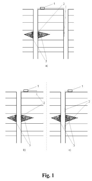
DETAILED DESCRIPTION
[0013] The proposed method is based on applying an electric field to a formation in which stimulation of a fluid inflow is performed. The effect of the electrical stimulation depends on physical parameters of the formation and is determined by positioning of electrodes, value and frequency of the electric field being created as well as a power of a power supply being used. The electric impact causes enhancement of physico-chemical processes in the formation and in space inside a wellbore during the stimulation of a fluid inflow into the wellbore. Thus, for example, the electric field causes the appearance of electric currents as well as an electro-kinetic, phenomena like electroosmosis or electrophoresis. These phenomena result in the motion of charged particles and the fluid and therefore result in the intensification of current physico-chemical processes. Additional application of magnetic field promotes additional motion of the charged particles. Extra temperature heating also causes the intensification of physico-chemical processes in the area being heated through intensification of the substances' thermal diffusion. Additional acoustic impact using a sound-emitting device also enhances the physico-chemical processes due to additional oscillations of the particles caused by the sound wave passage. Hereby any of the impacts above may be applied locally or directionally which enables intensification of the physico-chemical processes (such as chemical reaction speed) in the required area.
[0014] A system that allows to create an electric field inside a wellbore and a formation is shown on FIG. 1 where 1 is a current and voltage generator, 2—electrodes connected to the current and voltage generator 1, 3—a targeted zone of the formation in which stimulation of a fluid inflow is performed, chemicals have been injected into this targeted zone 3. For creating the electric field different combinations of electrodes positioning in the wellbore are possible, but at least one of the electrodes should be disposed in the wellbore at the level of the targeted zone 3 being treated. The other electrode may be located in an adjacent wellbore (see FIG. 1 a) or on the surface (see FIG. 1 b). The electrodes may also be disposed in the wellbore above and below the targeted zone 3 being treated (see FIG. 1 c). Casings and tubings may also be used as electrodes. A source of magnetic field can be placed into the wellbore at the level of the targeted zone 3 being treated. If a sound emitting device and/or a thermal heater is used they also can be disposed in the wellbore at the level of the targeted zone 3 being treated. Different components of the instruments used may be located both on the same device and on different and their power may be supplied by a cable or by batteries or accumulators.
[0015] As an example, three series of experiments were conducted in order to check the feasibility of described method. These experiments were carried out at room temperature 22° C. (72° F.). For the first experiment 750 ml of YF130LGD gel was prepared and put into a tank with plane electrodes attached thereto. The electrodes were connected to a standard power generating unit with AC output of 100V at ̃50 Hz. The distance between the electrodes was about 10 cm. After 15 minutes, only a slight gel destruction near the surface of the electrode was observed. That can be a result of local temperature increase up to 80° C. (180° F.) near the electrodes. The temperature was measured immediately after power was off.
[0016] For the second experiment two samples of YF130LGD hydraulic-fracture gel were prepared (500 ml each) and 2 g of J218 breaker was added to each gel sample. J218 breaker concentration for YF130LGD gel destruction is about 10 pounds/1000 gallons (1,2 kg/m3) that is two times lower than for carrying out this experiment. But it should be mentioned that the breaker operation temperature range is 52-107° C. (125-225° F.), moreover, the breaker is activated by adding special chemical catalysts. One sample of the prepared gel with the breaker portion was placed into a tank without electrodes and thoroughly mixed. The other sample was placed into the system with electrodes. After 7 minutes of AC applying it was detected that almost all gel (90%) in the tank under voltage was destroyed (the gel viscosity reduced to water viscosity value). In the tank without AC application only 10-15% gel was destroyed. During the second experiment the temperature value was 95° C. (200° F.) on the electrodes and 35° C. (95° F.) in the centre of the tank after 7 minutes of the AC impact.
[0017] The third experiment was performed to prove that at high temperatures there will be no gel destructions. For this purpose 500 ml of YF130LGD gel mixed with 2 g of J218 breaker was prepared and placed into a pre-heated tank, and then into an oven at 100° C. (210° F.). After 15 minutes of the temperature action destruction of maximum 25-30% of gel was noted.
[0018] Comparing the results of electrical field and temperature impact in presence of breaker, the advantage of the electrical field impact for the gel destruction becomes evident.
[0002] The invention is related to the well services in oil-field industry, particularly, to the methods for increasing permeability of a near-wellbore zone of a formation by stimulation of a fluid inflow into a wellbore.
BACKGROUND
[0003] A stimulation of a fluid inflow into a wellbore is required to recover and improve the near-wellbore zone filtration characteristics, basically through improved permeability of the near-wellbore zone and reduced fluid viscosity. Among the most efficient methods of the stimulation of fluids' influx from a formation are acid treatment and formation hydraulic fracturing (see, for example, V.I. Kudinov, Osnovy neftegazopromyslovogo dela ( Foundations of Oil and Gas Formation Industry), Moscow, 2005, pp. 428-429). Acid treatment and formation hydraulic fracturing enable stimulation of a fluid inflow into a wellbore by creating high-permeable paths for the fluid inflow into the wellbore hereby the selection of a specific treatment method and a quality of the works completed are critical for the efficiency of the future well operation. Thus, incorrectly performed fluid inflow stimulation may, for example, result in the need to completely stop the future wellbore operation. To intensify the fluid inflow during the matrix treatment and formation hydraulic fracturing various liquid and solid chemicals are injected into a wellbore. Thus, during hydraulic fracturing various substances are injected into a wellbore under large pressure which results in cracks in the rock. To prevent a closure of the cracks in the rock solid particles are injected into the wellbore using a viscous gel—propping agent (proppant). Due to high viscosity of the gel the crack becomes low-permeable and to improve its permeability, as a rule, reverse recirculation is used. To reduce the gel viscosity different chemicals—breakers—are added to the solution and, when penetrating the formation, they can reduce the gel viscosity. The chemicals being added are, as a rule, expensive, but not always efficient. Besides, engineers normally are not able to impact the breakers' activity after the chemicals have been injected into the wellbore. Therefore, among the key disadvantages of the existing methods for increasing the near-wellbore zone permeability are high costs, low speed and inability to monitor the reaction speed after the chemicals have been injected into the wellbore.
[0004] The proposed method provides for increased reliability and efficiency of stimulating a fluid inflow into a wellbore, enhanced speed of stimulating with simultaneous reduction of the risk of incorrect performing thereof as well as reduced costs.
SUMMARY
[0005] The method comprises carrying out a stimulation of a fluid flow into a wellbore comprising injecting chemical substances into a targeted zone of a formation and applying an electric field to the targeted zone of the formation.
[0006] The stimulation of the fluid flow into the wellbore is an acid formation treatment or a hydraulic fracturing of the formation.
[0007] Additional magnetic, thermal, acoustic treatment or a combination of thereof can be applied to the targeted zone of the formation zone during the stimulation.
[0008] The electric filed can be applied by electrodes. At least one of the electrodes is disposed in the wellbore on the level of the targeted zone.
[0009] One of the electrodes can be disposed in the wellbore on the level of the targeted zone and the other electrode can be disposed on the surface.
[0010] One of the electrodes can be disposed lower than the targeted zoned of the formation while the other can be disposed higher than the targeted zone of the formation being treated.
[0011] Casings and tubing can be used as the electrodes.
BRIEF DESCRIPTION OF THE DRAWINGS
[0012] The invention is explained by a drawing ( FIG. 1) showing a system providing an electric impact onto a formation in which stimulation of the fluid inflow is performed.
DETAILED DESCRIPTION
[0013] The proposed method is based on applying an electric field to a formation in which stimulation of a fluid inflow is performed. The effect of the electrical stimulation depends on physical parameters of the formation and is determined by positioning of electrodes, value and frequency of the electric field being created as well as a power of a power supply being used. The electric impact causes enhancement of physico-chemical processes in the formation and in space inside a wellbore during the stimulation of a fluid inflow into the wellbore. Thus, for example, the electric field causes the appearance of electric currents as well as an electro-kinetic, phenomena like electroosmosis or electrophoresis. These phenomena result in the motion of charged particles and the fluid and therefore result in the intensification of current physico-chemical processes. Additional application of magnetic field promotes additional motion of the charged particles. Extra temperature heating also causes the intensification of physico-chemical processes in the area being heated through intensification of the substances' thermal diffusion. Additional acoustic impact using a sound-emitting device also enhances the physico-chemical processes due to additional oscillations of the particles caused by the sound wave passage. Hereby any of the impacts above may be applied locally or directionally which enables intensification of the physico-chemical processes (such as chemical reaction speed) in the required area.
[0014] A system that allows to create an electric field inside a wellbore and a formation is shown on FIG. 1 where 1 is a current and voltage generator, 2—electrodes connected to the current and voltage generator 1, 3—a targeted zone of the formation in which stimulation of a fluid inflow is performed, chemicals have been injected into this targeted zone 3. For creating the electric field different combinations of electrodes positioning in the wellbore are possible, but at least one of the electrodes should be disposed in the wellbore at the level of the targeted zone 3 being treated. The other electrode may be located in an adjacent wellbore (see FIG. 1 a) or on the surface (see FIG. 1 b). The electrodes may also be disposed in the wellbore above and below the targeted zone 3 being treated (see FIG. 1 c). Casings and tubings may also be used as electrodes. A source of magnetic field can be placed into the wellbore at the level of the targeted zone 3 being treated. If a sound emitting device and/or a thermal heater is used they also can be disposed in the wellbore at the level of the targeted zone 3 being treated. Different components of the instruments used may be located both on the same device and on different and their power may be supplied by a cable or by batteries or accumulators.
[0015] As an example, three series of experiments were conducted in order to check the feasibility of described method. These experiments were carried out at room temperature 22° C. (72° F.). For the first experiment 750 ml of YF130LGD gel was prepared and put into a tank with plane electrodes attached thereto. The electrodes were connected to a standard power generating unit with AC output of 100V at ̃50 Hz. The distance between the electrodes was about 10 cm. After 15 minutes, only a slight gel destruction near the surface of the electrode was observed. That can be a result of local temperature increase up to 80° C. (180° F.) near the electrodes. The temperature was measured immediately after power was off.
[0016] For the second experiment two samples of YF130LGD hydraulic-fracture gel were prepared (500 ml each) and 2 g of J218 breaker was added to each gel sample. J218 breaker concentration for YF130LGD gel destruction is about 10 pounds/1000 gallons (1,2 kg/m3) that is two times lower than for carrying out this experiment. But it should be mentioned that the breaker operation temperature range is 52-107° C. (125-225° F.), moreover, the breaker is activated by adding special chemical catalysts. One sample of the prepared gel with the breaker portion was placed into a tank without electrodes and thoroughly mixed. The other sample was placed into the system with electrodes. After 7 minutes of AC applying it was detected that almost all gel (90%) in the tank under voltage was destroyed (the gel viscosity reduced to water viscosity value). In the tank without AC application only 10-15% gel was destroyed. During the second experiment the temperature value was 95° C. (200° F.) on the electrodes and 35° C. (95° F.) in the centre of the tank after 7 minutes of the AC impact.
[0017] The third experiment was performed to prove that at high temperatures there will be no gel destructions. For this purpose 500 ml of YF130LGD gel mixed with 2 g of J218 breaker was prepared and placed into a pre-heated tank, and then into an oven at 100° C. (210° F.). After 15 minutes of the temperature action destruction of maximum 25-30% of gel was noted.
[0018] Comparing the results of electrical field and temperature impact in presence of breaker, the advantage of the electrical field impact for the gel destruction becomes evident.
RU2132757
Method of Removing Hydrocarbons from Soil
FIELD:
oil pollution removal. SUBSTANCE: central and peripheral
electrodes are plunged into soil at area to be cleaned and
voltage gradient between electrodes is created. Then,
nonpolluting liquid carrier is fed into the surface region
around central electrode, which carrier moves under
electroosmosis effect from central electrode toward
peripheral electrodes and displaces hydrocarbons in soil
that are removed from peripheral electrodes. As liquid
carrier, water with pH 9 prepared by cavitation effect or
water with pH 5,5 prepared by heating is utilized.
Utilization of water taken from bed in oil and gas deposit
development is possible. EFFECT: enhanced cleaning
efficiency due to accelerated movement of liquid carrier and
reduced voltage gradient on electrodes.
A method for cleaning sand from petroleum products is known (as. USSR N 1629102, MKI 5: B 03 V 5/00, C 01 B 33/12, pub. 23.02.91 y. Bul-N-7-analogue.), Including sand treatment with an aqueous solution of hydrofluoric acid with a concentration of 0.5-2.0% by weight, with a ratio of the mass of solid soil to the liquid reagent as 1: (2-6) for 30 minutes.
The main disadvantage of this method is sand treatment with a chemical reagent, for neutralization it is necessary to add additional reagents and remove the reaction products of these reagents, which entails additional economic costs and does not increase the ecology of the cleaned sandy soil.
The closest in technical essence to the proposed invention is the method for removing contaminated soil (U.S. Patent No. 5,415,7774 A, MKI 6: B 01 D 61/56, published, ISM, No. 001, No. 10, 1996, p. 34 - prototype ), Including immersion in the soil on the cleared area of the central and peripheral electrodes, the creation of a voltage gradient between them, feeding the non-contaminating carrier fluid to the zone adjacent to the central one, moving the carrier fluid under the effect of the electroosmotic effect between the electrodes, displacing the carrier liquid of the contaminated Material from the soil to the peripheral electrodes and the removal of contaminated material from the latter.
This method is more ecological than the analogue. However, the motion of pure carrier fluids of the water type under the action of the electroosmotic effect is not intensive, and it is further slowed down when the carrier fluid displaces such impurities as viscous hydrocarbons such as oil, engine oil and the like. Especially large resistance to the displacement of the carrier fluid with hydrocarbons occurs in the cold season, when the viscosity of the latter increases. Therefore, to ensure the movement of the carrier fluid and viscous hydrocarbons, it is necessary to maintain a high voltage gradient, on the order of 380-500 V, depending on the soil structure, which leads to high energy costs and makes this method ineffective.
The purpose of the invention is to increase the efficiency of soil purification from hydrocarbons by accelerating the movement of the carrier fluid and reducing the voltage gradient at the electrodes.
The aim is achieved by the fact that in a method for purifying soil from hydrocarbons including immersion in the soil on the cleaning portion of the central and peripheral electrodes, creating between the first and second voltage gradients, feeding into the region adjacent to the central electrode not contaminating the carrier fluid, Carrier under the action of the electroosmotic effect from the central electrode to the peripheral electrode, displacement of hydrocarbon from the soil by the carrier fluid and their removal from the peripheral electrodes, as Carrier liquids use water in which the pH is changed to 9 by applying cavitation to it, or up to 5.5 by heating.
The use of water as the carrier fluid, in which the pH is changed to 9, by applying it to cavitation, or up to 5.5 by heating, has made it possible to increase the efficiency of soil purification at any temperatures without the use of chemical reagents and their neutralization.
The Applicant does not know how to purify soils that use water as the carrier fluid, in which the pH is changed to 9, influencing it by cavitation, or up to 5.5 by heating.
In Fig. 1 is a graph of the pH change of distilled and fresh water, depending on the time of action of cavitation.
In Fig. 2 is a plot of the pH of water versus its temperature.
In Fig. 3 is a flow diagram of an installation for implementing a method for cleaning soil from hydrocarbons.
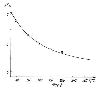
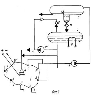
The proposed method for cleaning soil from hydrocarbons is as follows.
Due to the action of cavitation, the water molecules dissociate into H + and OH- ions. H + ions partially leave the liquid phase, and OH- ions accumulate in the latter, raising the pH of the water. In Fig. 1 is a graph of the pH change of distilled water and fresh water taken from different sources 2 and 3, depending on the time of action of the cavitation. Water with an elevated pH has a high surface activity and has high detergent properties.
Such water in contact with hydrocarbons - destroys the viscous surface film of hydrocarbons and intensively flushes them from the soil; - increases the dynamics of mixing of leachable hydrocarbons with them and forms an emulsion, which has a small hydraulic and low electrical resistance.
These properties increase the mobility in the soil of the formed liquid system (emulsion) under the action of the electroosmotic effect, which ultimately leads to a reduction of the voltage between the electrodes to 60 V and the cost of electricity and, as a consequence, to an increase in the efficiency of the method for cleaning the soil of hydrocarbons.
When the water is heated, its pH decreases and, as a result, its electrical conductivity increases. In Fig. 2 is a plot of the pH of water versus its temperature. As the pH of the water decreases, the solubility of hydrocarbons in it increases.
Such water when in contact with hydrocarbons - reduces their surface tension and viscosity; - forms a mobile electrically conductive emulsion.
These properties intensify the joint movement of water with hydrocarbons in the soil under the effect of the electroosmotic effect from the central electrode to the peripheral, which, as a consequence, leads to a decrease in the voltage between the electrodes to 60 V and the reduction of electricity costs and increases the efficiency of the method for cleaning the soil of hydrocarbons.
The proposed method for cleaning soil from hydrocarbons is similar in its intensity to methods for cleaning soil using chemical reagents such as surfactants with pH 9 and acids pH 5.5.
However, this method is environmentally friendly, does not require additional costs for chemical reagents and for their neutralization.
Compared with the prototype, this method is more effective than the prototype for energy costs in 6-7 times.
[3]
The method can be implemented with the apparatus shown in FIG. 3. The installation consists of immersed in the soil in the cleaning area 1 of the central 2 and peripheral 3 electrodes, a water supply nozzle 4, a pump 5 serving to remove water from the peripheral electrodes with hydrocarbons, a separator 6 for separating water and hydrocarbons, a container 7 with a nozzle Venturi 8 and heater 9, a pump 10 for injecting water into the nozzles 4 and a Venturi nozzle 8. The separator 6 and the tank 7 are connected by a pipeline through the water with a check valve 11. The container 7 is additionally connected to the nozzle 4 by a high-pressure water supply pipe 12 with a pH of 5.5.
An example of the execution of the method. Water with a temperature of 17 ° C, having a pH of 7.4, is supplied by a pump 10 from the tank 7 to the Venturi nozzle 8 at a speed of 30 m / s. The pressure of water flowing through the diffuser of the Venturi 8 nozzle is reduced to 2 x 10³ Pa. This causes cavitation of water. The cavitated liquid re-enters the vessel 7. The water is cavitated in this manner for 520 s, after which the water in the vessel has a pH of 9. The obtained surface active water by the pump 10 is fed through the nozzle 4 to the region adjacent to the central electrode 2. A voltage gradient of 60 V is created between the central and peripheral electrodes. Surface-active water with pH 9 under the action of the electroosmotic effect moves from the central electrode 2 to the peripheral 3. At the same time, it contacts hydrocarbons that pollute the soil, destroys their surface film and intensively flushes them from the soil. Surface-active water with pH 9 with hydrocarbons forms an emulsion that enters the peripheral electrodes 3, from where it is removed by pump 5 and fed to separator 6.
In the separator 6, the emulsion is divided into water at the bottom and hydrocarbons located at the top of the separator 6. The separated water enters the tank 7 through the check valve 11. The separated hydrocarbons are sent to storage tanks.
The described cycle is repeated until the hydrocarbons are completely removed from the soil. The process of cleaning the soil with surface active water obtained by cavitation is energetically beneficial at soil temperatures above 0oC.
In the case of soil cleaning with a temperature below 0oC from hydrocarbons, this water is used with water at pH 5.5, which is obtained by heating to 240oC in tank 7 using a heater 9. When the water in the tank 7 is heated, the pressure rises to 3.5 MPa. Under this pressure, water with a pH of 5.5 is fed, bypassing the pump 10, via the line 12 through the nozzle 4 to the work area 1. Further process of soil purification from hydrocarbons is carried out in a similar manner to the process described above.
A method for cleaning sand from petroleum products is known (as. USSR N 1629102, MKI 5: B 03 V 5/00, C 01 B 33/12, pub. 23.02.91 y. Bul-N-7-analogue.), Including sand treatment with an aqueous solution of hydrofluoric acid with a concentration of 0.5-2.0% by weight, with a ratio of the mass of solid soil to the liquid reagent as 1: (2-6) for 30 minutes.
The main disadvantage of this method is sand treatment with a chemical reagent, for neutralization it is necessary to add additional reagents and remove the reaction products of these reagents, which entails additional economic costs and does not increase the ecology of the cleaned sandy soil.
The closest in technical essence to the proposed invention is the method for removing contaminated soil (U.S. Patent No. 5,415,7774 A, MKI 6: B 01 D 61/56, published, ISM, No. 001, No. 10, 1996, p. 34 - prototype ), Including immersion in the soil on the cleared area of the central and peripheral electrodes, the creation of a voltage gradient between them, feeding the non-contaminating carrier fluid to the zone adjacent to the central one, moving the carrier fluid under the effect of the electroosmotic effect between the electrodes, displacing the carrier liquid of the contaminated Material from the soil to the peripheral electrodes and the removal of contaminated material from the latter.
This method is more ecological than the analogue. However, the motion of pure carrier fluids of the water type under the action of the electroosmotic effect is not intensive, and it is further slowed down when the carrier fluid displaces such impurities as viscous hydrocarbons such as oil, engine oil and the like. Especially large resistance to the displacement of the carrier fluid with hydrocarbons occurs in the cold season, when the viscosity of the latter increases. Therefore, to ensure the movement of the carrier fluid and viscous hydrocarbons, it is necessary to maintain a high voltage gradient, on the order of 380-500 V, depending on the soil structure, which leads to high energy costs and makes this method ineffective.
The purpose of the invention is to increase the efficiency of soil purification from hydrocarbons by accelerating the movement of the carrier fluid and reducing the voltage gradient at the electrodes.
The aim is achieved by the fact that in a method for purifying soil from hydrocarbons including immersion in the soil on the cleaning portion of the central and peripheral electrodes, creating between the first and second voltage gradients, feeding into the region adjacent to the central electrode not contaminating the carrier fluid, Carrier under the action of the electroosmotic effect from the central electrode to the peripheral electrode, displacement of hydrocarbon from the soil by the carrier fluid and their removal from the peripheral electrodes, as Carrier liquids use water in which the pH is changed to 9 by applying cavitation to it, or up to 5.5 by heating.
The use of water as the carrier fluid, in which the pH is changed to 9, by applying it to cavitation, or up to 5.5 by heating, has made it possible to increase the efficiency of soil purification at any temperatures without the use of chemical reagents and their neutralization.
The Applicant does not know how to purify soils that use water as the carrier fluid, in which the pH is changed to 9, influencing it by cavitation, or up to 5.5 by heating.
In Fig. 1 is a graph of the pH change of distilled and fresh water, depending on the time of action of cavitation.
In Fig. 2 is a plot of the pH of water versus its temperature.
In Fig. 3 is a flow diagram of an installation for implementing a method for cleaning soil from hydrocarbons.
The proposed method for cleaning soil from hydrocarbons is as follows.
Due to the action of cavitation, the water molecules dissociate into H + and OH- ions. H + ions partially leave the liquid phase, and OH- ions accumulate in the latter, raising the pH of the water. In Fig. 1 is a graph of the pH change of distilled water and fresh water taken from different sources 2 and 3, depending on the time of action of the cavitation. Water with an elevated pH has a high surface activity and has high detergent properties.
Such water in contact with hydrocarbons - destroys the viscous surface film of hydrocarbons and intensively flushes them from the soil; - increases the dynamics of mixing of leachable hydrocarbons with them and forms an emulsion, which has a small hydraulic and low electrical resistance.
These properties increase the mobility in the soil of the formed liquid system (emulsion) under the action of the electroosmotic effect, which ultimately leads to a reduction of the voltage between the electrodes to 60 V and the cost of electricity and, as a consequence, to an increase in the efficiency of the method for cleaning the soil of hydrocarbons.
When the water is heated, its pH decreases and, as a result, its electrical conductivity increases. In Fig. 2 is a plot of the pH of water versus its temperature. As the pH of the water decreases, the solubility of hydrocarbons in it increases.
Such water when in contact with hydrocarbons - reduces their surface tension and viscosity; - forms a mobile electrically conductive emulsion.
These properties intensify the joint movement of water with hydrocarbons in the soil under the effect of the electroosmotic effect from the central electrode to the peripheral, which, as a consequence, leads to a decrease in the voltage between the electrodes to 60 V and the reduction of electricity costs and increases the efficiency of the method for cleaning the soil of hydrocarbons.
The proposed method for cleaning soil from hydrocarbons is similar in its intensity to methods for cleaning soil using chemical reagents such as surfactants with pH 9 and acids pH 5.5.
However, this method is environmentally friendly, does not require additional costs for chemical reagents and for their neutralization.
Compared with the prototype, this method is more effective than the prototype for energy costs in 6-7 times.
[3]
The method can be implemented with the apparatus shown in FIG. 3. The installation consists of immersed in the soil in the cleaning area 1 of the central 2 and peripheral 3 electrodes, a water supply nozzle 4, a pump 5 serving to remove water from the peripheral electrodes with hydrocarbons, a separator 6 for separating water and hydrocarbons, a container 7 with a nozzle Venturi 8 and heater 9, a pump 10 for injecting water into the nozzles 4 and a Venturi nozzle 8. The separator 6 and the tank 7 are connected by a pipeline through the water with a check valve 11. The container 7 is additionally connected to the nozzle 4 by a high-pressure water supply pipe 12 with a pH of 5.5.
An example of the execution of the method. Water with a temperature of 17 ° C, having a pH of 7.4, is supplied by a pump 10 from the tank 7 to the Venturi nozzle 8 at a speed of 30 m / s. The pressure of water flowing through the diffuser of the Venturi 8 nozzle is reduced to 2 x 10³ Pa. This causes cavitation of water. The cavitated liquid re-enters the vessel 7. The water is cavitated in this manner for 520 s, after which the water in the vessel has a pH of 9. The obtained surface active water by the pump 10 is fed through the nozzle 4 to the region adjacent to the central electrode 2. A voltage gradient of 60 V is created between the central and peripheral electrodes. Surface-active water with pH 9 under the action of the electroosmotic effect moves from the central electrode 2 to the peripheral 3. At the same time, it contacts hydrocarbons that pollute the soil, destroys their surface film and intensively flushes them from the soil. Surface-active water with pH 9 with hydrocarbons forms an emulsion that enters the peripheral electrodes 3, from where it is removed by pump 5 and fed to separator 6.
In the separator 6, the emulsion is divided into water at the bottom and hydrocarbons located at the top of the separator 6. The separated water enters the tank 7 through the check valve 11. The separated hydrocarbons are sent to storage tanks.
The described cycle is repeated until the hydrocarbons are completely removed from the soil. The process of cleaning the soil with surface active water obtained by cavitation is energetically beneficial at soil temperatures above 0oC.
In the case of soil cleaning with a temperature below 0oC from hydrocarbons, this water is used with water at pH 5.5, which is obtained by heating to 240oC in tank 7 using a heater 9. When the water in the tank 7 is heated, the pressure rises to 3.5 MPa. Under this pressure, water with a pH of 5.5 is fed, bypassing the pump 10, via the line 12 through the nozzle 4 to the work area 1. Further process of soil purification from hydrocarbons is carried out in a similar manner to the process described above.
KR20010086551
Purification Method of Contaminated Soil with Petroleum Oil
PURPOSE:
A purification method of contaminated soil with petroleum
oil is provided, which can purify contaminated soil by
generating radical oxidant such as hydroxide radical using
metal peroxide such as calcium peroxide and magnesium
peroxide in the presence of a catalyst of iron and by
transferring the radical to contaminated area in soil by
electroosmosis. The method does not need any excavation and
transportation of soil and can remove more than 99 % of
contaminants. CONSTITUTION: The system comprises the
followings: (i) an acrylic box (10) which has an anode
chamber (16a) and a cathode chamber (16b) at both sides of
the box (10); (ii) anode chamber (16a) that is made of anode
diaphragm (15a), in which an anode (11a) is inserted and to
which discharge line of an electrode liquid supplement tank
(18) is inserted; and (iii) a cathode chamber (16b) that is
made of cathode diaphragm (15b), in which a cathode (11b) is
inserted and to which discharge line of an electroosmosis
liquid storage tank (19) is connected.
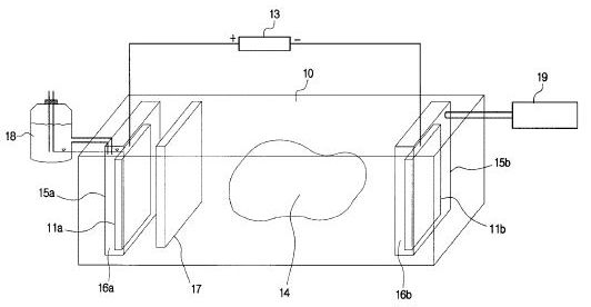
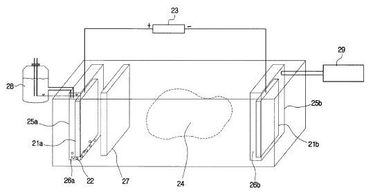
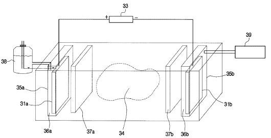
RU2602615
Method of Soil Cleaning from Hydrocarbons
FIELD:
ecology.SUBSTANCE: invention relates to environmental
protection, namely to reclamation of lands, contaminated
with hydrocarbons (oil products), decontamination of soil
from pesticides using phenomenon of electric osmosis. Method
of cleaning soil from oil products and pesticides using
electroosmosis consists in immersing of central and
peripheral electrodes into soil at section, undergoing
cleaning, creation of non-uniform electric field between
central and peripheral electrodes, supplying of
non-contaminating carrier fluid into area adjoining central
electrode, movement of carrier fluid under action of
electroosmotic effect from central electrode to peripheral
ones, removal of dirt beyond contaminated section,
displacement of contaminants from soil by carrier fluid and
removal thereof from peripheral electrodes, non-uniform
electric field intensity value is set within 50-110 kV/m,
before supplying carrier fluid soil is milled into particles
of 1.0 mm in depth of 20-25 cm. Milled soil is mixed with
carrier fluid to concentration of 1:6. Fluidized layer is
created by device in depth of 10-12 cm with supply of
compressed air of pressure 1-2 ATM. Proposed device
comprises central electrode and system of peripheral
electrodes, submerged into soil cleaning section, nozzle for
carrier fluid supply and removal of fluid, containing
contaminants, from cleaning section. Central electrode is
made in form of rod with cross section in form of polygon
with concave sides. System of peripheral electrodes is
composed by separate rods. Rods are connected by wire
conductors with sharp-pointed elements on them, point of
which is directed to central electrode. Ahead of nozzles for
supply of carrier fluid dispenser is placed. Above system of
peripheral electrodes device for creation of fluidized layer
is located, including central r-shape pipeline with
compressor, connected via control valve with system of
radial pipelines, at end of each of which nozzles are
located, submerged into soil for depth of 10-12 cm.EFFECT:
proposed method of soil cleaning from hydrocarbons and
pesticides and device for it provide maximum effect of soil
cleaning.
The invention relates to the protection of the environment, in particular to the reclamation of soils contaminated with hydrocarbons (oil products), the neutralization of soil from pesticides using the phenomenon of electroosmosis.
With the expansion of the use of pesticides, a number of negative consequences were identified: pollution of soils and water sources, accumulation of residues of chemicals in food. In soil, pesticides decay as a result of both physical-chemical processes and microbiological decomposition. Remnants of pesticides in the soil are washed out by storm and soil waters, gathering in natural reservoirs, polluting them, as well as surrounding land.
The problem of clearing lands and soils for agricultural purposes, the disposal of excess pollutants, especially those stored in the open way, is especially urgent for modern ecology. Currently, in the technology of agricultural production, herbicides have spread, as well as organochlorine pesticides: fusid-forte, zenkor, chistoplan, puma-super.
The disadvantage of the above analogs is the laboriousness of their application and the insufficient degree of soil purification from contamination.
The disadvantage of the prototype is the insufficient degree of soil purification from hydrocarbons, since cleaning with the use of electroosmosis is carried out in an insufficiently strong uneven electric field, as well as the lack of effective cleaning from pesticides.
The disadvantage of the above-mentioned analogue devices is also the insufficient degree of soil purification from pollution.
The disadvantage of the prototype is the ineffective cleaning of the soil from hydrocarbons (oil products) and the lack of purification from pesticides.
The task of the proposed method and device for its implementation is to increase the degree of soil purification from hydrocarbons (petroleum products), as well as soil cleaning from pesticides.
The technical result of the application of the method for cleaning the soil from hydrocarbons and pesticides is achieved by including immersion in the soil on the cleanable portion of the central and peripheral electrodes, creating an uneven electric field between the central and peripheral electrodes, feeding a non-polluting liquid to the region adjacent to the central electrode Carrier, the transport of the carrier fluid under the effect of the electroosmotic effect from the central electrode to the peripheral electrode, displacement from the soil by liquid-n And, in contrast to the prototype, the magnitude of the uneven electric field strength is set in the range of 50-110 kV / m, preliminary before feeding the carrier liquid, the soil is ground by means of a standard ripper in the form of a disk cutter to the particle size 1.0 mm at a depth of 20-25 cm, the ground soil is mixed with the carrier fluid to a concentration controlled by a doser of 1: 6, by means of an additionally installed device, a fluidized bed is formed with a depth 10-12 cm with the supply of compressed air at a pressure of 1-2 atm.
The technical result of using a soil cleaning device for hydrocarbons and pesticides is achieved by including a central electrode in the form of a rod with a cross-section in the form of a polygon with concave sides immersed in the soil, and a system of peripheral electrodes made of individual rods, Liquid carrier, pumps for injecting liquid into the nozzles and removing the contaminating liquid from the cleaning zone, in contrast to the prototype, a system of peripheral electrodes of soy The foam is interconnected by wire conductors with pointed elements attached to them, the point of which is directed to the central electrode, a dispenser is installed in front of the carrier liquid injectors, and a device for creating a fluidized bed is installed above the peripheral electrode system, including a central L- Connected through a distributor with a system of radial pipelines, at the end of each of which there are nozzles immersed in the soil to a depth of 10-12 cm.
The state of the art does not know the effect of the new set of features of the claimed method and device on the achievement of a new technical result - cleaning the soil of pesticides, which makes it possible to conclude that the technical solutions meet the criteria of "novelty" and "inventive level".
Soil cleaning from hydrocarbons and pesticides is as follows. On the area to be cleaned, a voltage gradient is created between the central and peripheral electrodes, the magnitude of the uneven electric field strength is set within 50-110 kV / m, fed to the region adjacent to the central electrode, the carrier fluid, the carrier fluid is transported by the electroosmotic effect from Central electrode to the peripheral, are displaced from the soil with the help of a carrier fluid and remove oil from peripheral electrodes.
Prior to supplying the carrier fluid to increase the degree of soil purification from hydrocarbons and pesticides, the soil is ground by means of a standard ripper in the form of a disk cutter to a particle size of 1.0 mm at a depth of 20-25 cm. The depth of soil grinding depends on the depth of penetration of pesticides, and this is determined by the depth of plowing, and by the technology of processing different crops an average of 10-12 cm. To create a fluidized bed to a depth of 10-12 cm, it is necessary to grind the contaminated soil with a ripper, respectively, to a depth of two times as much, which is 20-25 cm.
If the particle size is larger than 1.0 mm, then in the formation of a fluidized (boiling) layer of soil consisting of water droplets and air bubbles, the particles will soon be sedimented and settle on the site without sufficient purification. In the event that the particle size is less than 1.0 mm, the particles will migrate in the water-air phase.
The crushed soil particles are mixed with the carrier fluid to a concentration of 1: 6, which is determined by the flow of water through the circulating pump for supplying the carrier liquid and the dispenser. If the concentration of soil particles in the liquid phase is more than 1: 6, a suspension between the solid and liquid phase is not formed. Conversely, if the concentration of soil particles in the liquid phase is less than 1: 6, then in the resulting suspension the soil particles will not be sufficient to implement the method.
If the compressed air pressure is less than 1-2 atm, the formed fluidized bed can not penetrate to a depth of 10-12 cm, if the compressed air pressure is more than 1-2 atm, the depth of the fluidized bed will be greater than 10-12 cm, which will lead to Increased consumption of compressed air and energy costs for its production.
The efficiency of soil purification from hydrocarbons and pesticides increases due to physical processes occurring during the interaction of the fluidized bed with the uneven electric field of the indicated tension, which occur as follows.
It is known that when the carrier liquid is saturated with air in a ratio of 1: 6 (in our case), air bubbles are created in the liquid phase. Under the influence of an uneven electric field between the sharpened elements of the peripheral electrodes and the central electrode, air bubbles align along the lines of force of the field, then they elongate along the lines of force and decrease in the transverse direction. Compression of a bubble in the transverse direction means that compressive forces act near its equator. In this case, the air bubble behaves like a dielectric, the field inside it is slightly distorted. Further, it increases in all directions with the formation of a primary streamer that flies out of its tip (Korobeinikov SM The role of bubbles in the electrical breakdown of liquids. Thermophysics of High Temperatures, 1998, No. 3, pp. 362-367, 1998, No. 4, p. 541-547). The streammer is an ionized channel, obtained by overlapping individual electron avalanches occurring in its path.
The formation of streamers is accompanied by shock waves, whose center is the origin of the streamers, that is, the tip of the bubble. When the streamer channel develops, the surface of the bubbles turns to be charged, a volume discharge develops over the surface of the bubbles as a result of the action of the streamers in a two-phase medium (a mixture of water and soil), ozone and a number of active particles are generated, including the OH radical, atomic oxygen, Formed ozone decomposes pesticides, up to the mineralization. In addition, the hard ultraviolet radiation of the plasma takes place. Also, during the development of electrical breakdown, a powerful shock wave is formed, which has an additional disinfection effect on the soil.
It is known that the electric field E of a charged cylinder of radius r is determined by the formula (1) (Koshkin NI Handbook on elementary physics .- M .: Nauka, 1980):
Table 1
In Fig. 1 is a schematic diagram of an apparatus for carrying out a process for cleaning soil from hydrocarbons and pesticides; FIG. 2 is a device for creating a fluidized bed.
FIG. 1 is a schematic diagram of an apparatus for carrying out the method,
FIG. 2 shows a fluidized bed apparatus
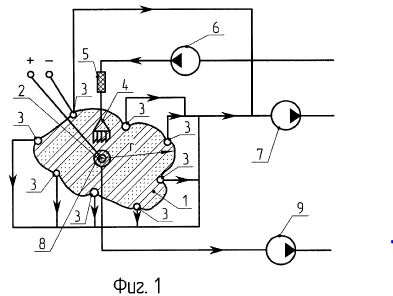
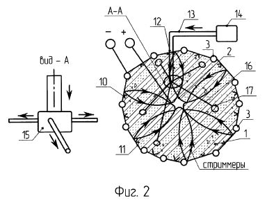
The scheme of the device (Figure 1) shows: the cleaning zone 1, immersed in the soil of the cleaning zone, the central electrode (anode) 2, the peripheral electrode system (cathodes) 3, the injector 4 for feeding the carrier fluid, the dispenser 5 for creating a controlled liquid concentration A pump 7 for removing liquid containing oil products from the peripheral electrodes, a pump 6 for injecting the carrier liquid into the injector 4 through a dispenser 5, a pump 9 for evacuating contaminants containing petroleum products and pesticides from the perforated pipe 8.
The system of peripheral electrodes is made of individual rods 3 connected with each other by wire conductors 11 (fig.2) with pointed elements 10 on it, the point of which is directed to the central electrode. For grinding the soil, use a standard ripper in the form of a disk cutter. A device 12 for creating a fluidized bed is provided above the peripheral electrode system including a central L-shaped conduit 13 with a compressor 14 connected through a distributor 15 to a system of radial conduits 16 at the end of which are installed injectors 17 for supplying compressed air into the fluidized bed immersed in the soil To a depth of 10-12 cm.
The proposed method for cleaning the soil is carried out using the device as follows.
A serial ripper in the form of a disk mill cuts the soil to a particle size of 1.0 mm. In soil crushed to a depth of 20-25 cm, the pump 6 is fed through a nozzle 4 with a carrier fluid.
Turn on the pumps 6 and 7. The ground soil is then mixed with the carrier fluid by means of a pump 6 and a dispenser 5 to a concentration of 1: 6. Electrodes 2 and 3 are supplied with a voltage, the value of which is set within 50-110 kV / m, as a result, an uneven electric field is created between the protrusions of the central electrode and the pointed elements. The carrier fluid under the effect of the electroosmotic effect flows from the central electrode 2 to the peripheral electrode system 3, sorbing oil products or pesticides in its path, then the impurities are removed by the pump 7.
The fluidized bed using the device is constructed as follows. From the compressor 14, compressed air is injected through a central L-shaped conduit connected through a distributor 15 and a system of radial conduits 16 with injectors 17 at a pressure of 1-2 atm. And air bubbles appear. In this case, under the influence of an uneven electric field between the sharpened elements of the peripheral electrodes 3 and the central electrode 2, air bubbles are aligned along the lines of force. Further on, at the tip of the bubble, the formation of a streamer takes place, which flies into the cleaning zone. As a result of the action of streamers in a two-phase medium, ozone and a number of active particles are generated (OH radical, atomic oxygen, etc.). The ozone formed decomposes pesticides up to their mineralization.
The invention relates to the protection of the environment, in particular to the reclamation of soils contaminated with hydrocarbons (oil products), the neutralization of soil from pesticides using the phenomenon of electroosmosis.
With the expansion of the use of pesticides, a number of negative consequences were identified: pollution of soils and water sources, accumulation of residues of chemicals in food. In soil, pesticides decay as a result of both physical-chemical processes and microbiological decomposition. Remnants of pesticides in the soil are washed out by storm and soil waters, gathering in natural reservoirs, polluting them, as well as surrounding land.
The problem of clearing lands and soils for agricultural purposes, the disposal of excess pollutants, especially those stored in the open way, is especially urgent for modern ecology. Currently, in the technology of agricultural production, herbicides have spread, as well as organochlorine pesticides: fusid-forte, zenkor, chistoplan, puma-super.
A method for
cleaning a capillary-porous medium contaminated with oil
and oil products is known, by introducing a solution of
oil-oxidizing microorganisms into the cleaning zone,
introducing an electroconductive liquid, passing an
electric current to create an electroosmosis (RU
96115094 A, IPC B09C 1/10, publ. 27.11.1998).
There is a known
method for restoring contaminated soils contaminated
with different in composition and properties
(heterogeneous), including applying a material for
purification from contaminants to the heterogeneous soil
area, passing a constant electric current between the
electrodes within the contaminated heterogeneous soil,
applying a hydraulic gradient across the contamination
area (RU 2143954 C1, IPC B09C 1/08, publ. 10.01.2000).
The disadvantage of the above analogs is the laboriousness of their application and the insufficient degree of soil purification from contamination.
The closest
analogue of the method adopted as a prototype is a
method for cleaning the soil, including immersion in the
soil on the cleaned portion of the central and
peripheral electrodes, creating a voltage gradient
between the central and peripheral electrodes, feeding
into the region adjacent to the central electrode not
contaminating the carrier fluid , Displacement of the
carrier fluid under the effect of the electroosmotic
effect from the central electrode to the peripheral
electrode, displacement of the hydrocarbon carrier from
the soil, removal x of the peripheral electrodes,
creating an uneven electric field between the central
and peripheral electrodes (RU 2508954 C1, IPC B09C 1/00,
publ. 10.03.2014).
The disadvantage of the prototype is the insufficient degree of soil purification from hydrocarbons, since cleaning with the use of electroosmosis is carried out in an insufficiently strong uneven electric field, as well as the lack of effective cleaning from pesticides.
A device is known
for applying a method for cleaning from contamination of
a capillary-porous medium, comprising a chamber for
placing a cleaned medium with electrodes connected to a
DC source, a container with a liquid to be cleaned and a
container for the spent liquid (RU 2106432 C1, MPC
<6> C25C 1/22 , Publ. 10.03.1998).
A plant for
processing soils and soils is known (RU 2330734 C1, IPC
B09C 11/00, publ. 10.08.2008), containing a hopper with
a stirring device, with a device for transporting liquid
therefrom to the overflow tank and a device for removing
solid inclusions, a washing liquid supply system, a
vibrator.
The disadvantage of the above-mentioned analogue devices is also the insufficient degree of soil purification from pollution.
The closest to the
proposed device for implementing the method adopted for
the prototype is a device comprising a central electrode
and a peripheral electrode system immersed in the soil,
a nozzle for supplying the carrier liquid, pumps for
injecting liquid into the nozzles and removing the
contaminating liquid from the Cleaning zone, the central
electrode is made in the form of a rod, the cross
section of which is a polygon with concave sides (RU
2508954 C1, IPC B09C 1/00, publ. 10.03.2014).
The disadvantage of the prototype is the ineffective cleaning of the soil from hydrocarbons (oil products) and the lack of purification from pesticides.
The task of the proposed method and device for its implementation is to increase the degree of soil purification from hydrocarbons (petroleum products), as well as soil cleaning from pesticides.
The technical result of the application of the method for cleaning the soil from hydrocarbons and pesticides is achieved by including immersion in the soil on the cleanable portion of the central and peripheral electrodes, creating an uneven electric field between the central and peripheral electrodes, feeding a non-polluting liquid to the region adjacent to the central electrode Carrier, the transport of the carrier fluid under the effect of the electroosmotic effect from the central electrode to the peripheral electrode, displacement from the soil by liquid-n And, in contrast to the prototype, the magnitude of the uneven electric field strength is set in the range of 50-110 kV / m, preliminary before feeding the carrier liquid, the soil is ground by means of a standard ripper in the form of a disk cutter to the particle size 1.0 mm at a depth of 20-25 cm, the ground soil is mixed with the carrier fluid to a concentration controlled by a doser of 1: 6, by means of an additionally installed device, a fluidized bed is formed with a depth 10-12 cm with the supply of compressed air at a pressure of 1-2 atm.
The technical result of using a soil cleaning device for hydrocarbons and pesticides is achieved by including a central electrode in the form of a rod with a cross-section in the form of a polygon with concave sides immersed in the soil, and a system of peripheral electrodes made of individual rods, Liquid carrier, pumps for injecting liquid into the nozzles and removing the contaminating liquid from the cleaning zone, in contrast to the prototype, a system of peripheral electrodes of soy The foam is interconnected by wire conductors with pointed elements attached to them, the point of which is directed to the central electrode, a dispenser is installed in front of the carrier liquid injectors, and a device for creating a fluidized bed is installed above the peripheral electrode system, including a central L- Connected through a distributor with a system of radial pipelines, at the end of each of which there are nozzles immersed in the soil to a depth of 10-12 cm.
The state of the art does not know the effect of the new set of features of the claimed method and device on the achievement of a new technical result - cleaning the soil of pesticides, which makes it possible to conclude that the technical solutions meet the criteria of "novelty" and "inventive level".
Soil cleaning from hydrocarbons and pesticides is as follows. On the area to be cleaned, a voltage gradient is created between the central and peripheral electrodes, the magnitude of the uneven electric field strength is set within 50-110 kV / m, fed to the region adjacent to the central electrode, the carrier fluid, the carrier fluid is transported by the electroosmotic effect from Central electrode to the peripheral, are displaced from the soil with the help of a carrier fluid and remove oil from peripheral electrodes.
Prior to supplying the carrier fluid to increase the degree of soil purification from hydrocarbons and pesticides, the soil is ground by means of a standard ripper in the form of a disk cutter to a particle size of 1.0 mm at a depth of 20-25 cm. The depth of soil grinding depends on the depth of penetration of pesticides, and this is determined by the depth of plowing, and by the technology of processing different crops an average of 10-12 cm. To create a fluidized bed to a depth of 10-12 cm, it is necessary to grind the contaminated soil with a ripper, respectively, to a depth of two times as much, which is 20-25 cm.
If the particle size is larger than 1.0 mm, then in the formation of a fluidized (boiling) layer of soil consisting of water droplets and air bubbles, the particles will soon be sedimented and settle on the site without sufficient purification. In the event that the particle size is less than 1.0 mm, the particles will migrate in the water-air phase.
The crushed soil particles are mixed with the carrier fluid to a concentration of 1: 6, which is determined by the flow of water through the circulating pump for supplying the carrier liquid and the dispenser. If the concentration of soil particles in the liquid phase is more than 1: 6, a suspension between the solid and liquid phase is not formed. Conversely, if the concentration of soil particles in the liquid phase is less than 1: 6, then in the resulting suspension the soil particles will not be sufficient to implement the method.
If the compressed air pressure is less than 1-2 atm, the formed fluidized bed can not penetrate to a depth of 10-12 cm, if the compressed air pressure is more than 1-2 atm, the depth of the fluidized bed will be greater than 10-12 cm, which will lead to Increased consumption of compressed air and energy costs for its production.
The efficiency of soil purification from hydrocarbons and pesticides increases due to physical processes occurring during the interaction of the fluidized bed with the uneven electric field of the indicated tension, which occur as follows.
It is known that when the carrier liquid is saturated with air in a ratio of 1: 6 (in our case), air bubbles are created in the liquid phase. Under the influence of an uneven electric field between the sharpened elements of the peripheral electrodes and the central electrode, air bubbles align along the lines of force of the field, then they elongate along the lines of force and decrease in the transverse direction. Compression of a bubble in the transverse direction means that compressive forces act near its equator. In this case, the air bubble behaves like a dielectric, the field inside it is slightly distorted. Further, it increases in all directions with the formation of a primary streamer that flies out of its tip (Korobeinikov SM The role of bubbles in the electrical breakdown of liquids. Thermophysics of High Temperatures, 1998, No. 3, pp. 362-367, 1998, No. 4, p. 541-547). The streammer is an ionized channel, obtained by overlapping individual electron avalanches occurring in its path.
The formation of streamers is accompanied by shock waves, whose center is the origin of the streamers, that is, the tip of the bubble. When the streamer channel develops, the surface of the bubbles turns to be charged, a volume discharge develops over the surface of the bubbles as a result of the action of the streamers in a two-phase medium (a mixture of water and soil), ozone and a number of active particles are generated, including the OH radical, atomic oxygen, Formed ozone decomposes pesticides, up to the mineralization. In addition, the hard ultraviolet radiation of the plasma takes place. Also, during the development of electrical breakdown, a powerful shock wave is formed, which has an additional disinfection effect on the soil.
It is known that the electric field E of a charged cylinder of radius r is determined by the formula (1) (Koshkin NI Handbook on elementary physics .- M .: Nauka, 1980):
Where k is the
coefficient of proportionality, k = 8.9875 * 10 <9>
m / F;
Q - electric
charge, q = 2,3467 * 10 <-2> Cl;
R is the radius of
the cleaning zone;
Ε is the
permittivity of the medium.
It is known that,
depending on the amount of humus, the amount of water,
the viscosity of the soil, the permittivity of the soil
is ε = 19.2; 23.8; 26.7; 41,2 (Bobrov PP, Belyaeva TV
Experimental check of the model of complex dielectric
permittivity of soils and viscosity of soil moisture. //
Natural sciences and ecology. Yearbook of the Omsk GPU.
2002. - p. 29-33).
The results of
calculating the electric field strength from formula (1)
for r = 10 m are given in Table. 1.
Table 1
Calculations show
that for a given range from 19.2 to 41.2 changes in the
dielectric permittivity of the soil, the electric field
strength ranges from 50 to 110 kV / m.
In Fig. 1 is a schematic diagram of an apparatus for carrying out a process for cleaning soil from hydrocarbons and pesticides; FIG. 2 is a device for creating a fluidized bed.
FIG. 1 is a schematic diagram of an apparatus for carrying out the method,
FIG. 2 shows a fluidized bed apparatus
The scheme of the device (Figure 1) shows: the cleaning zone 1, immersed in the soil of the cleaning zone, the central electrode (anode) 2, the peripheral electrode system (cathodes) 3, the injector 4 for feeding the carrier fluid, the dispenser 5 for creating a controlled liquid concentration A pump 7 for removing liquid containing oil products from the peripheral electrodes, a pump 6 for injecting the carrier liquid into the injector 4 through a dispenser 5, a pump 9 for evacuating contaminants containing petroleum products and pesticides from the perforated pipe 8.
The system of peripheral electrodes is made of individual rods 3 connected with each other by wire conductors 11 (fig.2) with pointed elements 10 on it, the point of which is directed to the central electrode. For grinding the soil, use a standard ripper in the form of a disk cutter. A device 12 for creating a fluidized bed is provided above the peripheral electrode system including a central L-shaped conduit 13 with a compressor 14 connected through a distributor 15 to a system of radial conduits 16 at the end of which are installed injectors 17 for supplying compressed air into the fluidized bed immersed in the soil To a depth of 10-12 cm.
The proposed method for cleaning the soil is carried out using the device as follows.
A serial ripper in the form of a disk mill cuts the soil to a particle size of 1.0 mm. In soil crushed to a depth of 20-25 cm, the pump 6 is fed through a nozzle 4 with a carrier fluid.
Turn on the pumps 6 and 7. The ground soil is then mixed with the carrier fluid by means of a pump 6 and a dispenser 5 to a concentration of 1: 6. Electrodes 2 and 3 are supplied with a voltage, the value of which is set within 50-110 kV / m, as a result, an uneven electric field is created between the protrusions of the central electrode and the pointed elements. The carrier fluid under the effect of the electroosmotic effect flows from the central electrode 2 to the peripheral electrode system 3, sorbing oil products or pesticides in its path, then the impurities are removed by the pump 7.
The fluidized bed using the device is constructed as follows. From the compressor 14, compressed air is injected through a central L-shaped conduit connected through a distributor 15 and a system of radial conduits 16 with injectors 17 at a pressure of 1-2 atm. And air bubbles appear. In this case, under the influence of an uneven electric field between the sharpened elements of the peripheral electrodes 3 and the central electrode 2, air bubbles are aligned along the lines of force. Further on, at the tip of the bubble, the formation of a streamer takes place, which flies into the cleaning zone. As a result of the action of streamers in a two-phase medium, ozone and a number of active particles are generated (OH radical, atomic oxygen, etc.). The ozone formed decomposes pesticides up to their mineralization.
As a result, the
degree of soil purification from hydrocarbons (oil, oil,
fuel oil, etc.) and pesticides rises to 98-99%.
KR101464878
Remediation System for Multi-Contaminated Soils
An aspect of the present invention provides a remediation system for complexly contaminated soil using a combined chemical oxidation and soil flushing method by electrokinetic remediation that increases the remediation efficiency of complexly contaminated soil as a treatment region is formed by hydrogen peroxide inserted into one side of a soil cell from an anode cell to induce the oxidation and decomposition of oil contaminants and the oil contaminants are oxidized and decomposed by being flushed and adsorbed by an anionic surface active agent inserted into the other side of the soil cell from a cathode cell to be moved into the treatment region. The remediation system for complexly contaminated soil using a combined chemical oxidation and soil flushing method by electrokinetic remediation according to an embodiment of the present invention comprises: a soil cell complexly contaminated by oil contaminants and heavy metal contaminants; an anode cell having an anode inserted into one side of the soil cell; a cathode cell having a cathode inserted into the other side of the soil cell to be separated from the anode by a certain distance; a hydrogen peroxide supply cell connected to the anode cell to supply hydrogen peroxide to one side of the soil cell; a first anionic surface active agent supply cell connected to the cathode cell to supply a first anionic surface active agent to the other side of the soil cell; and a power supply device for flushing and adsorbing oil contaminants via electric ion movement using the first anionic surface active agent to be moved from the cathode to the treatment region while simultaneously forming the treatment region, which is defined by the flowing distance of hydrogen peroxide, so that oil contaminants can be oxidized and decomposed as hydrogen peroxide is moved from the anode to the cathode via electroosmosis by supplying power to the anode and the cathode.
US4645004
Electro-Osmotic Production of Hydrocarbons Utilizing Conduction Heating of Hydrocarbon Formations
An
electro-osmotic method for the production of hydrocarbons
utilizes in situ heating of earth formations having
substantial electrical conductivity. A particular volume of
an earth formation is bounded with a waveguide structure
formed of respective rows of discrete elongated electrodes
in a dense array wherein the active electrode area and the
row separation are chosen in reference to the deposit
thickness to avoid heating barren layers. Electrical power
is applied at no more than a relatively low frequency
between respective rows of electrodes to deliver power to
the formation while producing relatively uniform heating
thereof and limiting the relative loss of heat to adjacent
regions to less than a predetermined amount. At the same
time the temperature of the electrodes is controlled near
the vaporization point of water to maintain an electrically
conductive path between the electrodes and the formation. A
heat sink is provided by supplying aqueous liquid
electrolyte to space between the electrodes and the adjacent
formation, thereby maintaining the temperature thereat no
greater than about the boiling point of water and
maintaining a conductive path between said formation. A d.c.
polarized potential is applied to enhance flow of reservoir
fluid into a preselected row of electrodes, and collected
reservoir fluids are removed from the electrodes in the
preselected row.
BACKGROUND OF THE INVENTION
This invention relates generally to the exploitation of hydrocarbon-bearing formations having substantial electrical conductivity, such as tar sands and heavy oil deposits, by the application of electrical energy to heat the deposits. More specifically, the invention relates to the delivery of electrical power to a conductive formation at relatively low frequency or d.c., which power is applied between rows of elongated electrodes forming a waveguide structure bounding a particular volume of the formation, while at the same time the temperature of the electrodes is controlled.
Materials such as tar sands and heavy oil deposits are amenable to heat processing to produce gases and hydrocarbons. Generally the heat develops the porosity, permeability and/or mobility necessary for recovery. Some hydrocarbonaceous materials may be recovered upon pyrolysis or distillation, others simply upon heating to increase mobility.
Materials such as tar sands and heavy oil deposits are heterogeneous dielectrics. Such dielectric media exhibit very large values of conductivity, relative dielectric constant, and loss tangents at low temperature, but at high temperatures exhibit lower values for these parameters. Such behavior arises because in such media ionic conducting paths or layers are established in the moisture contained in the interstitial spaces in the porous, relatively low dielectric constant and loss tangent rock matrix. Upon heating, the moisture evaporates, which radically reduces the bulk conductivity, relative dielectric constant, and loss tangent to essentially that of the rock matrix.
It has been known to heat electrically relatively large volumes of hydrocarbonaceous formations in situ. Bridges and Taflove U.S. Pat. No. Re. 30,738 discloses a system and method for such in situ heat processing of hydrocarbonaceous earth formations wherein a plurality of elongated electrodes are inserted in formations and bound a particular volume of a formation of interest. As used therein, the term "bounding a particular formation" means that the volume is enclosed on at least two sides thereof. The enclosed sides are enclosed in an electrical sense with a row of discrete electrodes forming a particular side. Electrical excitation between rows of such electrodes established electrical fields in the volume. As disclosed in such patent, the frequency of the excitation was selected as a function of the bounded volume so as to establish a substantially nonradiating electric field which was confined substantially in the volume. The method and system of the reissue patent have particular application in the radio-frequency heating of moderately lossy dielectric formations at relatively high frequency. However, it is also useful in relatively lossy dielectric formations where relatively low frequency electrical power is utilized for heating largely by conduction. The present invention is directed toward the improvement of such method and system for such heating of relatively conductive formations at relatively low frequency and to the application of such system for heating with d.c.
SUMMARY OF THE INVENTION
For electrically heating conductive formations, it is desirable to utilize relatively low frequency electrical power or d.c. to achieve relatively uniform heating distribution along the line. At low frequency, it is necessary that conductive paths remain conductive between the subsurface electrodes and the formation being heated. It is also desirable to heat the formation as fast as possible in order to minimize heat outflow to barren regions. This presents certain inconsistent requirements, as fast heating requires a large amount of heat at the electrodes, and the resultant high temperatures boil away the water needed to maintain the conductive paths. On the other hand, if the heating proceeds slowly, excessive temperatures leading to vaporization of water and consequent loss of conductivity are avoided, but there is economically wasteful loss of heat to the barren formations in the extended time needed to heat the deposit of interest.
It is a primary aspect of the present invention to provide compromises to best meet such disparate requirements in the in situ heating of earth formations having substantial conductivity. A waveguide structure as shown in the reissue patent is emplanted in the earth to bound a particular volume of an earth formation with a waveguide structure formed of respective rows of discrete elongated electrodes wherein the spacing between rows is greater than the distance between electrodes in a respective row and in the case of vertical electrodes substantially less than the thickness of the hydrocarbonaceous earth formation. Electrical power at no more than a relatively low frequency is applied between respective rows of the electrodes to deliver power to the formation while producing relatively uniform heating thereof and limiting the relative loss of heat to adjacent barren regions to less than a tolerable amount. At the same time the temperature of the electrodes is controlled near the vaporization point of water thereat to maintain an electrically conductive path between the electrodes and the formation. A d.c. polarized potential is applied to enhance flow of reservoir fluid toward at least one preselected electrode.
A waveguide electrical array which employs a limited number of small diameter electrodes would be less expensive to install than an array using more electrodes but would result in excess electrode temperature and nonuniform heating and consequently inefficient use of electrical power. On the other hand, a dense array, that is, one in which the spacing s between rows is greater than the distance d between electrodes in a row, would be somewhat more costly, but would heat more uniformly and more rapidly and, therefore, be more energy efficient.
A key to optimizing these conflicting factors is to control the temperature of the electrodes and the resource immediately adjacent the electrodes by properly selecting the deposit gas pressure, heating rates, heating time, final temperature, electrode geometry and positioning and/or cooling the electrodes.
These and other aspects and advantages of the present invention will become more apparent from the following detailed description, particularly when taken in conjunction with the accompanying drawings.
BRIEF DESCRIPTION OF THE DRAWINGS
FIG. 1 is a vertical sectional view, partly diagrammatic, of a preferred embodiment of a system for the conductive heating of an earth formation in accordance with the present invention, wherein an array of electrodes is emplaced vertically, the section being taken transversely of the rows of electrodes;
FIG. 2 is a diagrammatic plan view of the system shown in FIG. 1;
FIG. 3 is an enlarged vertical sectional view, partly diagrammatic, of part of the system shown in FIG. 1;
FIG. 4 is a vertical sectional view, partly diagrammatic, of an alternative system for the conductive heating of an earth formation in accordance with the present invention, wherein an array of electrodes is emplaced horizontally, the section being taken longitudinally of the electrodes;
FIG. 5 is a vertical sectional view, partly diagrammatic of the system shown in FIG. 4, taken along line 5--5 of FIG. 4;
FIG. 6 is a vertical sectional view comparable to that of FIG. 4 showing an alternative system with horizontal electrodes fed from both ends;
FIG. 7 is a plan view, mostly diagrammatic, of an alternative system comparable to that shown in FIG. 3, with cool walls adjacent electrodes;
FIG. 8 is a vertical sectional view, partly diagrammatic of the system shown in FIG. 7, taken along line 8--8 of FIG. 7;
FIG. 9 is a set of curves showing the relationship between a time dependent factor c and heat loss and a function of deposit temperature utilizing the present invention;
FIG. 10 is a set of curves showing the temperature distribution at different heating rates when heat is delivered to a defined volume;
FIG. 11 is a set of curves showing the relationship between time and temperature at different points when a formation is heated by a sparse array;
FIG. 12 is a set of curves showing the relationship between time and temperature at different points when a formation is heated in accordance with the present invention with electrode diameters of 32 inches; and
FIG. 13 is a set of curves showing the relationship of time and temperature at the same points as in FIG. 12 in accordance with the present invention with electrode diameters of 14 inches.
DETAILED DESCRIPTIONS OF THE PREFERRED EMBODIMENTS
FIGS. 1, 2 and 3 illustrate a system for heating conductive formations utilizing an array 10 of vertical electrodes 12, 14, the electrodes 12 being grounded, and the electrodes 14 being energized by a low frequency or d.c. source 16 of electrical power by means of a coaxial line 17. The electrodes 12, 14 are disposed in respective parallel rows spaced a spacing s apart with the electrodes spaced apart a distance d in the respective rows. The electrode array 10 is a dense array, meaning that the spacing s between rows is greater than the distance d between electrodes in a row. The rows of electrodes 12 are longer than the rows of electrodes 14 to confine the electric fields and consequent heating at the ends of the rows of electrodes 14.
The electrodes 12, 14 are tubular electrodes emplaced in respective boreholes 18. The electrodes may be emplaced from a mined drift 20 accessed through a shaft 22 from the surface 24 of the earth. The electrodes 12 preferably extend, as shown, through a deposit 26 or earth formation containing the hydrocarbons to be produced. The electrodes 12 extend into the overburden 28 above the deposit 26 and into the underburden 30 below the deposit 26. The electrodes 14, on the other hand, are shorter than the electrodes 12 and extend only part way through the deposit 26, short of the overburden 28 and underburden 30. In order to avoid heating the underburden and to provide the power connection, the lower portions of the electrodes 14 may be insulated from the formations by insulators 31, which may be air. The effective lengths of the electrodes 14 therefore end at the insulators 31.
FIGS. 4 and 5 illustrate a system for heating conductive formations utilizing an array 32 of horizontal electrodes 34, 36 disposed in vertically spaced parallel rows, the electrodes 34 being in the upper row and the electrodes 36 in the lower row. The upper electrodes 34 are preferably grounded, and the lower electrodes 36 are energized by a low frequency or d.c. source 38 of electrical power. The electrodes 34, 36 are disposed in parallel rows spaced apart a spacing s, with the electrodes spaced apart a distance d in the respective rows. The electrode array 32 is also a dense array. The upper row of electrodes 34 is longer than the lower row of electrodes 36 to confine the electric fields from the electrodes 36. The electrodes 34 extend beyond both ends of the electrodes 36 for the same reason. Grounding the upper electrodes 34 keeps down stray fields at the surface 24 of the earth.
The electrodes 34, 36 are tubular electrodes emplaced in respective boreholes 40 which may be drilled by well known directional drilling techniques to provide horizontal boreholes at the top and bottom of the deposit 26 between the overburden 28 and the underburden 30. Preferably the upper boreholes are at the interface between the deposit 26 and the overburden 28, and the lower boreholes are slightly above the interface between the deposit 26 and the underburden 30.
FIG. 6 illustrates a system comparable to that shown in FIGS. 4 and 5 wherein the array is fed from both ends, a second power source 42 being connected at the end remote from the power source 38.
FIGS. 7 and 8 illustrate a system comparable to that of FIGS. 1, 2 and 3 with an array of vertical electrodes. In this system the rows of like electrodes 12, 14 are in spaced pairs to provide a low field region 44 therebetween that is not directly heated to any great extent.
The deposit thickness h and the average or effective thermal diffusion properties determine the uniformity of the temperature distribution as a function of heating time t and can be generally described for any thickness of a deposit in the terms of a deposit temperature profile factor c, such that
c=kt/(h/2)@2
where k is the thermal diffusivity. FIG. 9 presents a curve A showing the relationship between the factor c and the portion of a deposit above 80% of the temperature rise of the center of the deposit for a uniform heating rate through the heated volume. Note that at c=0.1, about 75% of the heated volume has a temperature rise greater than 80% of the temperature rise of the center of the heated volume.
FIG. 10 illustrates the heating profiles for three values of the factor c as a function of the distance from the center of the heated volume, the fraction of the temperature rise that would have been reached in the heated volume in the absence of heat outflow. Note that where c=0.1 or c=0.2, the total percentage of heat lost to adjacent formations is relatively small, about 10% to 15%. Where low final temperatures, e.g., less than 100 DEG C., are suitable, c up to 0.3 can be accepted, as the heat lost, or extra heat needed to maintain the final temperature, is, while significant, economically acceptable. FIG. 9, curve B, showing percent heat loss as a function of the factor c, shows percent heat loss to be less than 25% at c=0.3. On the other hand, if higher temperatures (e.g., about 200 DEG C.) are desired to crack the bitumen, then higher central deposit temperatures above the design minimum are needed to process more of the deposit, especially if longer heating times are employed. Moreover, the heat outflows at these higher temperatures are more economically disadvantageous. Thus a temperature profile factor of c less than about 0.15 is required. In general the heating rate should be great enough that c is less than 30 times the inverse of the ultimate increase in temperature AT in degrees celsius of the volume:
c.ltoreq.0.3(100/.DELTA.T)
The lowest values of c are controlled more by the excess temperature of electrodes and are discussed below.
The electrode spacing distance d and diameter a are determined by the maximum allowable electrode temperature plus some excess if some local vaporization of the electrolyte and connate water can be tolerated. In a reasonably dense array, the hot regions around the electrodes are confined to the immediate vicinity of the electrodes. On the other hand, in a sparse array, where s is no greater than d, the excess heat zone comprises a major portion of the deposit.
FIG. 11 illustrates a grossly excessive heat build-up on the electrodes as compared to the center of the deposit for a sparse array. In this example row spacing s was 10 m, electrode spacing d 10 m, electrode diameter a 0.8 m, and thermal diffusivity 10@-6 m@2 /s, with no fluid flow.
FIG. 12 shows how the electrode temperature can be reduced by the use of a dense array. In this example row spacing s was 10 m, electrode spacing d 4 m, electrode diameter a 0.8 m, and thermal diffusivity 10@-6 m@2 /s, with no fluid flow.
FIG. 13 illustrates the effect of decreasing the diameter of the electrodes of the dense array of FIG. 12 such that the temperature of the electrode is increased somewhat more relative to the main deposit. In this example row spacing s was 10 m, electrode spacing d 4 m, electrode diameter a 0.35 m, and thermal diffusivity 10@-6 m@2 /s, with no fluid flow. The region of increased temperature is confined to the immediate vicinity of the electrode and does not constitute a major energy waste. Thus, varying the electrode separation distance d and the diameter of the electrode a permit controlling the temperature of the electrode either to prevent vaporization or excessive vaporization of the electrolyte in the borehole and connate water in the formations immediately adjacent the electrode.
The electrode spacing d and diameter a are chosen so that either electrodetemperature is comparable to the vaporization temperature, or if some local vaporization is tolerable (as for a moderately dense array), the unmodified electrode temperature rise without vapor cooling will not significantly exceed the vaporization temperature.
The means for providing water for both vaporization and for maintenance of electrical conduction is shown in the drawings, particularly in FIG. 3 for vertical electrodes and in FIG. 4 for horizontal electrodes. As shown in FIG. 3, a reservoir 46 of aqueous electrolyte provides a conductive solution that may be pumped by a flow regulator and pump 47 down the shaft 22 and up the interior of the electrodes 12 and into the spaces between the electrodes 12 and the formation 26. A vapor relief pipe 48, together with a pressure regulator and pump 50 returns excess electrolyte to the reservoir 46 and assures that the electrolyte always covers the electrodes 12. Similarly, a reservoir 52 provides such electrolyte down the shaft 22, whence it is driven by a pressure regulator and pump 53 up the interior of the electrodes 14 and into the spaces between the electrodes 14 and the formation 26. In this case the electrodes are energized and not at ground potential. The conduits 54 carrying the electrolyte through the shaft 22 are therefore at the potential of the power supply and must be insulated from ground, as is the reservoir 52. The conduits 54 are therefore in the central conductor of the coaxial line 17. The electrodes 14 have corresponding vapor relief pipes 56 and a related pressure regulator and pump 58.
As shown in FIG. 4, electrolyte is provided as needed from reservoirs 60, 61 to the interior tubing 62 which also acts to connect the power source 38 to the respective electrodes 34, 36, the tubing being insulated from the overburden 28 and the deposit 26 by insulation 64. The electrolyte goes down the tubing 62 to keep the spaces between the respective electrodes 34, 36 and the deposit 26 full of conductive solution during heating. The tubing to the lower electrode 36 may later be used to pump out the oil entering the lower electrode, using a positive displacement pump 66.
In either system, the electrolyte acts as a heat sink to assure cool electrodes and maintain conductive paths between the respective electrodes and the deposit. The water in the electrolyte may boil and thereby absorb heat to cool the electrodes, as the water is replenished.
The vaporization temperature is controlled by the maximum sustainable pressure of the deposit. Typically for shallow to moderate depth deposits the gauge pressure can range from a few psig to 300 psig with a maximum of about 1300 psig for practical systems. The tightness of adjacent formations also influences the maximum sustainable vapor pressure. In some cases, injection of inert gases to assist in maintaining deposit pressure may be needed.
Another way to keep the electrodes cool is to position the electrodes adjacent a reduced field region on one side of an active electrode row. This reduces radically the heating rate in the region of the diminished field, thus creating in effect a heat sink which radically reduces the temperature of the electrodes, in the limiting case to about half the temperature rise of the center portion of the deposit.
As shown in FIGS. 7 and 8, in the case of vertical arrays, pairs of electrodes 12, 14 can be installed from the same drift and the same potential is applied to each pair, thus the regions 44 between the pairs become low field regions. By proper selection of heating rates and pair separation, it is possible to control the temperature of the electrode at slightly below that for the center of the deposit. The thickness of the cool wall region 44 can be sufficiently thin that the cool wall region can achieve about 90% of the maximum deposit temperature via thermal diffusion from the heated volume after the application of power has ended.
As shown in FIGS. 4, 5 and 6 in the case of a horizontally enlarged biplate, a nearly zero field region exists on the barren side of the row of grounded upper electrodes 34 and a nearly zero field region exists on the barren side of the row of energized electrodes 36. Such low field regions act as the regions 44 in the system shown in FIGS. 7 and 8.
The arrangement of FIGS. 4, 5 and 6 with the upper electrodes grounded is superior to other arrangements of horizontal electrodes in respect to safety. No matter how the biplate rows are energized and grounded (such as upper electrode energized and lower electrode grounded, vice versa or both symmetrically driven in respect to ground) leakage currents will flow near the surface 24 that may be small but significant in respect to safety and equipment protection. These currents will create field gradients which, although small, can be sufficient to develop hazardous potentials on surface or near-surface objects 68, such as pipelines, fences and other long metallic structures, or may destroy operation of above-ground electrical equipment. To mitigate such effects, ground mats can be employed near metallic structures to assure zero potential drops between any metallic structures likely to be touched by anyone.
These safety ground mats as well as electrical system grounds will collect the stray current from the biplate array. These grounds then serve in effect as additional ground electrodes of a line. Leakage currents between the grounding apparatus at the surface and the biplate array also heat the overburden, especially if the uppermost row is excited and the deposit is shallow. Thus biplate arrays, although having two sets of electrodes of large areal extent, also implicitly contain a third but smaller set of electrodes 68 near the surface at ground potential. Although this third set of electrodes collects diminished currents, the design considerations previously discussed to prevent vaporization of water in the earth adjacent the other electrodes must also be applied.
The near surface ground currents are minimized if the upper electrodes 34 are grounded and the lower electrodes 36 are energized. Also the grounded upper electrodes 34 can be extended in length and width to provide added shielding. This requires placing product collection apparatus at the potential of the energized lower set of electrodes by means of isolation insulation. However, this arrangement reduces leakage energy losses as compared to other electrodes energizing arrangements. Such leakage currents tend to heat the overburden 28 between the row of upper electrodes 34 and the above-ground system 68, giving rise to unnecessary heat losses.
Short heating times stress the equipment, and therefore, the longest heating times consistent with reasonable heat losses are desirable. This is especially true for the horizontal biplate array. The conductors of an array in the biplate configuration, especially if it is fairly long, will inject or collect considerable current. The amount of current at the feed point will be proportional to the product of the conductor length l, the distance d between electrodes within the row, and the current density J needed to heat the deposit to the required temperature in time t. Thus the current I per conductor becomes at the feed point (assuming small attenuation along the line):
I=(J) (l) (d) ##EQU1## where
.sigma. is the conductivity of the reservoir and joules-to-heat is the energy required to heat a cubic meter to the desired temperature. Thus the current carrying requirement of the conductors at the feed points is reduced by increasing the heat up time t as determined by the maximum allowable temperature profile factor c and deposit thickness h. Further, making the array more dense, that is, decreasing d, also reduces the current carrying requirements as well as decreasing l. If conductor current at the feed point is excessive, heat will be generated in the electrode due to I@2 R losses along the conductor. The power dissipated in the electrode due to I@2 R losses can significantly exceed the power dissipated in the reservoir immediately adjacent the electrode. This can cause excessive heating of the electrode in addition to the excess heat generated in the adjacent formation due to the concentration of current near the electrode. Thus another criterion is that the I@2 R conductor losses not be excessive compared to the power dissipated in the media due to narrowing of the current flow paths into the electrodes. Also the total collected current should not exceed the current carrying rating of the cable feed systems.
Another cause of excess temperature of the electrodes over that for the deposit arises from fringing fields near the sides of the row of excited electrodes. Here the outermost electrodes (in a direction transverse to the electrode axis) carry additional charges and currents associated with the fringing fields. As a consequence, both the adjacent reservoir dissipation and I@2 R longitudinal conductor losses will be significantly increased over those experienced for electrodes more centrally located. To control the temperature of these outermost electrodes, several methods can be used, including: (1) increasing the density of the array in the outermost regions, (2) relying on additional vaporization to cool these electrodes, and (3) the enlarging the diameter of these electrodes. Some cooling benefit will also exist for the cool-wall approach, especially in the case of the vertical electrode arrays if an additional portion of the deposit can be included in the reduced field region near the outermost electrodes. Applying progressively smaller potentials as the outermost electrodes are neared is another option.
In the case of the biplate array, especially if it extends a great length into the deposit, such as over 100 m, special attention must be given to the path losses along the line. To alleviate the effects of such attenuation, the line may be fed from both ends, as shown in FIG. 6. At the higher frequencies, these are frequency dependent and are reduced as the frequency is decreased. Perhaps not appreciated in earlier work, is that there is a limit to how much the path attenuation can be reduced by lowering the frequency. The problem is aggravated because, as the deposit is heated, it becomes more conducting.
A buried biplate array or triplate array exhibits a path loss attenuation .alpha. of
.alpha.=8.7[(R+j.omega.L)(G+j.omega.C)]@1/2 dB/m
where
R is the series resistance per meter of the buried line, which includes an added resistance contribution from skin effects in the conductor, if present,
L is the series inductance per meter of the buried line,
G is the shunt conductance over a meter for the line and is directly proportional to .sigma., the conductivity of the deposit,
C is the shunt capacitance over a meter for the line. Where conduction currents dominate, G>>j.omega.c, so that the attenuation .alpha. becomes
.alpha.=8.7[(R+j.omega.L)(G)]@1/2 dB/m
If the frequency .omega. is reduced, j.omega.L is radically reduced, R is partially decreased (owing to a reduction in skin effect loss contribution) and G tends to remain more or less constant. Eventually, as frequency .omega. is decreased, R>>j.omega.L, usually at a near zero frequency condition, so that
.alpha.=8.7[(R)(G)]@1/2 dB/m
If thin wall steel is used as the electrode material, unacceptable attenuation over fairly long path lengths could occur, especially at the higher temperatures where conductance G and conductivity .sigma. are greater. If thin walled copper or aluminum is used for electrodes (these may be clad with steel to resist corrosion), the near zero-frequency attenuation can be acceptably reduced so that
.alpha.l=8.7[(R)(G)]@1/2 (l).ltoreq.2dB
for the single end feed of FIG. 4 and less than 8 dB for the double end feed of FIG. 6.
When d.c. power is applied, advantage may be taken of electro-osmosis to promote the production of liquid hydrocarbons. In the case of electro-osmosis, water and accompanying oil drops are usually attracted to the negative electrodes. The factors affecting electro-osmosis are determined in part by the zeta potentials of the formation rock, and in some limited cases the zeta potentials may be such that water and oil are attracted to the positive potential electrodes.
Electro-osmosis can also be used to cause slow migration of the reservoir water toward one of the sets of electrodes preferentially. This preferential migration will be toward the cathode for typical reservoirs. However, depending upon the salinity of the reservoir fluids and the mineralogy of the reservoir matrix, the net movement under application of d.c. can be toward the anode. Remote ground can be used as an opposing electrode to facilitate this. This can be used to replenish conductivity in formations around the desired electrodes of sets of electrodes by resaturating the formation using reservoir fluids. This will permit resumption of heating.
In some cases, the presence of water fills the available pore spaces and thereby suppresses the flow of oil. Also in the case of a heavy oil deposit, influx of water from the lower reaches of the deposit may reach the producing electrodes such as electrodes 36 (FIG. 6). Therefore, in some cases it may be desirable to place a potential onto both sets of electrodes 34, 36 such that water is drawn away from the array. This may be done by modifying the source 38 such that the ground electrode array 68 near the surface is placed at a negative potential with respect to the entire set of deep electrodes 34, 36.
D.C. power applied for electro-osmosis can cause anodic dissolution of the metal electrodes, and hence, it will be preferable to keep the d.c. power levels just high enough to cause migration of fluids. Such required d.c. power can either be added as a bias to a.c. power which provides the bulk of the energy required to heat the formation or be applied intermittently.
While the use of electro-osmotic effects to enhance recovery from single wells or pairs of wells has been described, the employment of the dense array offers unique features heretofore unrecognized. For example, in the case of a pair of electrodes widely separated, the direct current emerges radially or spherically from the electrode. The radially divergent current produces a radially divergent electric field, and since the electro-osmotic effect is proportional to the electric field, the beneficial effects of electro-osmosis are evident only very near the electrode. Furthermore, the amount of current which can be introduced by an electrode is restricted by vaporization consideration or, if the deposit is pressurized, by a high temperature coking condition which may plug the producing capillary paths. On the other hand, with the arrangement of the present invention, the large electrode surface area and the controlled temperature below the vaporization point allows substantially more d.c. current to be introduced. Further, the effects of electro-osmosis are felt throughout the deposit, as uniform current flow and electric fields are established throughout the bulk of the deposit. Thus an electro-osmotic fluid drive phenomenon of substantial magnitude can be established throughout the deposit which can substantially enhance the production rates.
Further, electrolyte fluids will be drawn out of the electrodes which are not used to collect the water. Therefore, means to replace this electrolyte must be provided.
Production of liquid hydrocarbons using electro-osmosis can also be practiced in combination with conventional recovery techniques such as gravity drainage. Electro-osmosis can be used to increase the rate of production of liquid hydrocarbons by gravity drainage. For example, the polarity of the electrode rows shown in FIG. 5 can be so chosen such that reservoir water will slowly move toward the upper row of electrodes 34. This will cause a simultaneous increase in saturation of hydrocarbons toward the bottom row of electrodes 36. The rate of flow of hydrocarbons toward these bottom electrodes 36 is directly proportional to the permeability of the formation near the electrodes to flow of hydrocarbons. This in turn increases with increase in hydrocarbon saturation. Thus, the rate of hydrocarbon production can be increased by forcing the reservoir water to move toward the upper part of the formation by electro-osmosis.
Although various preferred embodiments of the present invention have been described in some detail, various modifications may be made therein within the scope of the invention.
Several methods of production are possible beyond the unique features of electro-osmosis. Typically, the oil can be recovered via gravity or autogenously generated vapor drives into the perforated electrodes, which can serve as product collection paths. Provision for this type of product collection is illustrated in FIG. 4, where a positive displacement pump 66 located in the lowest level of electrode 36 can be used to recover the product. Product can be collected in some cases during the heat-up period. For example, in FIG. 4 the reservoir fluids will tend to collect in the lower electrode array. If those are produced during heating, those fluids can provide an additional or substitute means to control the temperature of the lower electrode. On the other hand, it may not be desirable to produce a deposit, if in situ cracking is planned, until the final temperature is reached.
Various "hybrid" production combinations may be considered to produce the deposit after heating. These could include fire-floods, steam floods and surfactant/polymer water floods. In these cases, one row of electrodes can be used for fluid injections and the adjacent row for fluid/product recovery.
In contrast with polarizing the electrodes so as to suppress the production of water, the electro-osmotic forces can be used as a drive mechanism which exists volumetrically throughout the deposit for a fluid replacement type flood. The principal benefits of using the electro-osmotic drive in conjunction with the electrode arrays discussed here is that the volumetric drive can be maintained without excessive heat being developed near the electrode or without excessive electrolysis as might occur in a simple five-spot well arrangement.
The fluids injected at the electrodes can contain surfactants such as long chain sulfonates or amines or polymers such as polyacrylamides. The presence of surfactants will reduce the interfacial tension between the injected fluids and the liquid hydrocarbons and will help in recovering the liquid hydrocarbons. Addition of polymers will increase the viscosity and cause an improvement in sweep efficiency. The applied d.c. power can act as the driving force for the migration of fluids toward the other set of eIectrodes, whereby the accompanying liquid hydrocarbons can be produced along with the drive fluid.
The foregoing discussion, for simplicity, has limited consideration to either vertical or horizontal electrode arrays. However, arrays employed at an angle with respect to the deposit may be useful to minimize the number of drifts and the number of boreholes. In this case, the maximum row separation s is chosen to be midway between the vertical or horizontal situation, such that if largely vertical, the row separation s is not much greater than that found for the true vertical case. On the other hand, if the rows are nearly horizontal, then a value of s closer to that chosen for a horizontal array should be used.
WO2012158145
Method for Electrokinetic Prevention of Scale Deposition in Oil Producing Well Bores
Method
of using direct current (DC) electrokinetics to alleviate
and prevent scale deposition in and around well bores, e.g.,
the well bores of oil producing wells.
FIELD OF THE INVENTION
The present invention relates generally to the prevention of mineral scale deposition in a well bore, and more particularly to a method for electrokinetically preventing mineral scale deposition in oil well bores with the aid of DC electric current.
BACKGROUND OF THE INVENTION
The waterflood, a secondary enhanced oil recovery process/<11> is a simple, low cost, and proven approach for pressure maintenance and for driving oil towards a production well.
Though initial waterflooding attempts were used to rectify plugged wells or casing leaks, the apparent benefits led to broader applications <pl>. Waterflood efficiency depends on oil viscosity, permeability, wettability, structural considerations, uniformity of reservoir rock, and type of flood<[2]>. The volume of liquid produced partly determines the volume of water required for injection<111>. For economic reasons nearby seawater is commonly used, where available, as the injection water type to save money on water transportation. The mixing of incompatible injection seawater and formation water frequently produces mineral scale deposits, one of the most significant and costly problems encountered in oilfield operations <[3> Water flooding operations conducted in the Abu Dhabi oilfields often result in the formulation of BaS04, CaS04 and SrS04 deposits. The S04<2"> and Ba<2+> ion content in both seawater and formation water, respectively, can easily reach the solubility product (Ks) causing accumulation of BaS04 scale on surface and subsurface equipment. This is recognized as a major cause of formation damage in production or injection wells. Inorganic scale contributes to wear, corrosion, and flow restriction, resulting in a decrease of oil and gas production. This scale also deposits in downhole pumps, tubing, casing, flow lines, heaters, treaters, tanks and other production equipment and facilities<131>. Barium sulfate (BaS04) scale is among the toughest to remove either by mechanical or chemical means. BaS04 is typically removed by mechanical tools that involve abrasion, such as gauge cutters, nipple brushes and spinning wash tools. Chemical removal methods utilizing ethylenediaminetetraacetic acid (EDTA) are also available<[3>
Unfortunately, current scale inhibitor applications incur high costs due to conventional chemical dissolution. Scale inhibitor treatment is limited by its "squeeze efficiency" into the formation, which results in limited penetration as well as quick consumption in the reservoir. A squeeze usually involves the application of pump pressure to force a treatment fluid or slurry into a planned treatment zone (Schlumberger Oilfield Glossary). The problem is that scale inhibitors do not move deeply into the reservoir, hence only a small volume can be squeezed before being rapidly consumed. A need exists for a new methodology to prevent scale formation which is both economical and effective.
While electrically enhanced techniques for promoting oil recovery are known, including those described in United States Patent Nos. 5,614,077 and 7,325,604, such techniques have not been applied in the fashion described herein for preventing mineral scale deposits.
SUMMARY OF THE INVENTION
The method of the invention involves the application of electrokinetics for mitigating mineral scale formation. In one embodiment, the present invention provides an electrokinetic method for preventing mineral scale deposition in an oil well, having a well bore in fluid communication with an oil-bearing formation in which water and positively and negatively charged scale-forming species are present. The method comprises the steps of:
a) positioning at least one first electrode adjacent to a well bore;
b) positioning at least one second electrode at a location spaced apart from the first electrode and within electrical current conducting proximity of the first electrode;
c) applying a potential difference between the first electrode(s) and the second electrode(s) using a direct current (DC) power source, the potential difference producing an electrical current flow between the first electrode(s) and the second electrode(s), whereby the positively charged scale-forming species are caused to migrate toward one of the first and the second electrode(s), and the negatively charged scale-forming species are caused to migrate toward the other of the first and second electrode(s). In an aspect of this method, the potential difference is applied such that the first electrode(s) serves as one or more cathodes and the second electrode(s) serves as one or more anodes.
In another aspect of this method, at least one of the positively and negatively charged scale-forming species is introduced into the formation from an external source such as waterflooding. When waterflooding is the source of the scale-forming species, the method may be performed using an electrically conducting aqueous solution, e.g., a prepared or manmade aqueous salt solution, or alternatively, an aqueous solution selected from the group consisting of seawater, groundwater, surfacewater, and wastewater.
In a further aspect of the method, the positively and negatively charged scale-forming species include at least one alkaline earth metal ion and sulfate or carbonate ions.
In still a further aspect of the electrokinetic method, multiple cathodes are positioned in the vicinity of the well. Additionally, multiple anodes may be positioned at locations spaced apart from the cathodes and beyond the well, and in preferred installations the number of anodes exceeds the number of cathodes.
In yet another embodiment, the present invention provides an electrokinetic method for preventing mineral scale deposition in an oil well, and the vicinity of the well, with the well having a well bore in fluid communication with an oil-bearing formation in which water and positively and negatively charged scale-forming species are present, the method comprising the steps of:
a) positioning at least one cathode adjacent to the well bore;
b) positioning a plurality of anodes at a location spaced apart from the at least one cathode and within electrical current conducting proximity of the at least one cathode, wherein the number of anodes exceeds the number of cathodes;
c) applying a potential difference between the at least one cathode and each individual anode of the plurality of anodes; whereby electrical current flow between the at least one cathode and each individual anode of the plurality of anodes causes the positively charged scale-forming species to migrate toward the at least one cathode, and the negatively charged scale-forming species to migrate toward each individual anode of the plurality of anodes.
In another aspect, the method further comprises the step of providing a switch between the at least one cathode and each individual anode of the plurality of anodes, wherein the switch is adapted to be opened to interrupt application of the potential difference between the at least one cathode and each individual anode of the plurality of anodes, or closed to apply the potential difference between the at least one cathode and each individual anode of the plurality of anodes.
In a further aspect of the method of the invention, the step of applying a potential difference between the at least one cathode and each individual anode of the plurality of anodes further comprises the step of providing a DC power source between the at least one cathode and each individual anode of the plurality of anodes.
The method described herein is believed to be the first use of direct current to prevent scale deposition in a well bore in fluid communication with an oil bearing formation. The electrokinetic method for preventing scale deposition described herein may be categorized as a green technology, since there is no water consumption, and no air, water, or formation pollution. The technology can be applied without depth limitations in situ, thereby making it an attractive option in remote or environmentally challenging operating locations.
BRIEF DESCRIPTION OF THE DRAWINGS
The following description will be more easily understood when read in conjunction with the accompanying figures in which:
FIGURES 1A-C are circuit diagrams representing cathode and an anode configurations where the number of anodes exceeds the number of cathodes.
FIGURE 2 is a graphical representation of the pressure across the core versus time in experiment 1 of Example 1.
FIGURES 3A-C are a set of graphs showing the barium concentration profiles of the experiments in Example 1 ; Figure 3A is a graphical representation of the concentration profile of barium found in the tested electrode configuration (++--) for all tested salinity and
composition waters against the blank at the five strategic sampled positions across the 18 cm sand specimen of Example 1; Figures 3B-C are graphs representing the concentration profile of barium remaining after application of DC current; where Figure 3B includes the average of experiments 1 and 10 in addition to experiments 2, 5, 8 - seawater/formation composition water (SW/FW) and 11 of Experiment 1; and Figure 3C includes experiments 5, 8, 9 and 12 of Example 1. FIGURE 4 is a graph of the current across the core as a function of time for experiment 2 of Example 1.
FIGURES 5A-C are a set of graphs showing current as a function of time across the core for several experiments of Example 1 ; Figure 5A is a graph of the current across the core as a function of time for experiment 3 of Example 1; Figure 5B is a graph of the current across the core as a function of time for experiment 5 of Example 1 ; and Figure 5C is a graph of the current across the core versus time for experiment 8 of Example 1.
FIGURES 6A-C are a set of graphs showing pressure as a function of current across the core for several experiments of Example 1; Figure 6A is a graph of the pressure versus current for experiment 2 of Example 1 ; Figure 6B is a graph of the pressure as a function of current for experiment 3 of Example 1 ; and Figure 6C is a graph of the pressure as a function of current for experiment 8 of Example 1.
FIGURE 7 is a graph of the standardized concentration profile of barium with and without DC current - No salinity and actual seawater/formation composition water (SW/FW) of Example l(see Table 3).
FIGURE 8 is a graphical representation of the change in permeability with respect to the pore volume in the blank experiment of Example 2.
FIGURE 9 is a schematic illustration of a consolidated sand cell shown, in cross-section, with an electrode positioned at each of the production water outlet and the sea water inlet.
FIGURES 10A-B are schematic illustrations of the electrokinetic cell utilized in
Example 2; Figure 10A is a schematic illustration of a consolidated sand cell showing, in cross- section, the distribution of anodes and cathodes in a first configuration (AAACC), and Figure 10B is a schematic illustration of a consolidated sand cell shown, in cross-section, a distribution of anodes and cathodes in the second configuration (AAAAC).
FIGURE 11 is a graphical representation of the effect of pH on BaS04 solubility.
FIGURES 12 A-F are a set of graphs showing permeability as a function of pore volume for several experiments of Example 2; Figure 12A is a graphical representation of permeability reduction with respect to the pore volume in experiment 5 of Example 2; Figure 12B is a graphical representation of permeability reduction with respect to the pore volume in experiment 6 of Example 2; Figure 12C is a graphical representation of permeability reduction with respect to the pore volume in experiment 7 of Example 2; Figure 12D is a graphical representation of permeability reduction with respect to the pore volume in experiment 8 of Example 2; Figure 12E is a graphical representation of permeability reduction with respect to the pore volume in experiment 9 of Example 2; and Figure 12F is a graphical representation of permeability reduction with respect to the pore volume in experiment 10 of Example 2.
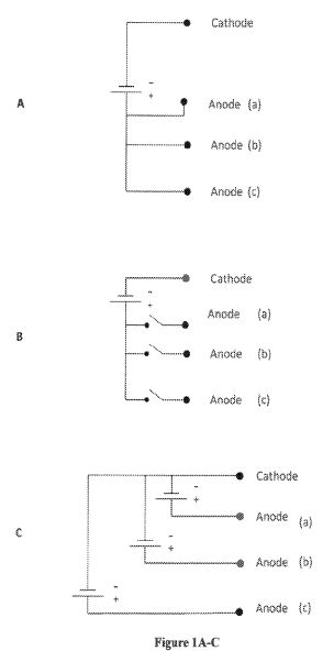
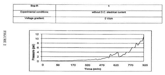
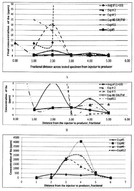
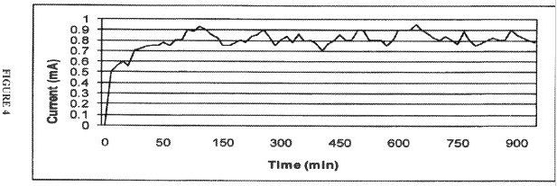
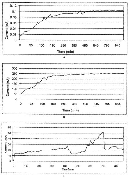
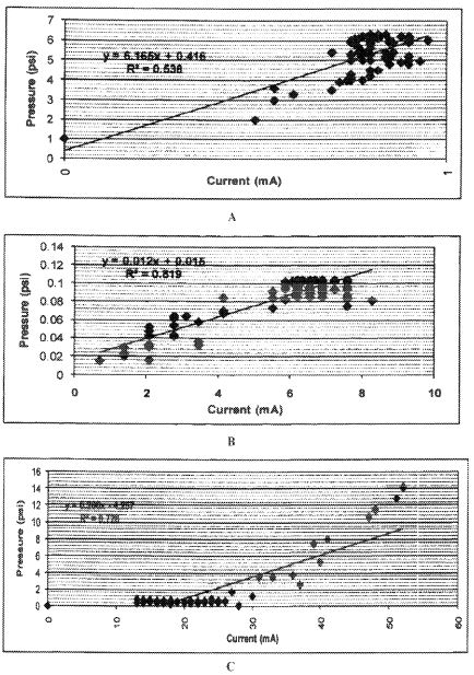
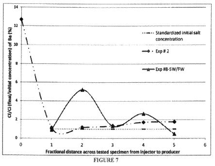
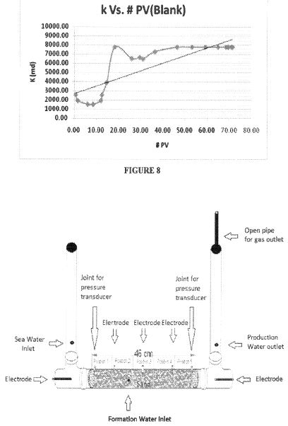
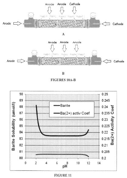
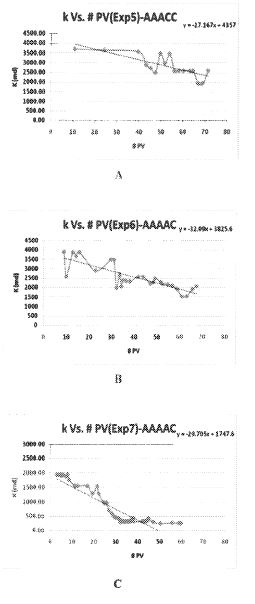
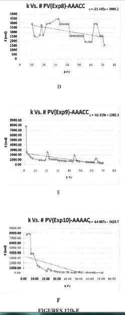