Warren RICE, et al
Electromagnetic Ship Propulsion
Popular
Science (January 1966); "Silent Sea Engine for
Nuclear Subs"
Popular Science (January 1966), pp.
113-115; "How to Build Your Own Sea Engine"
Product Engineering (February 24,
1969); "Magnetic Propulsion May Be Ready For Small Subs"
Discover Magazine (May, 1980s); "The
Magnetic Ship"
Warren A. Rice, Warren: US Patent #
2,997,013; "Propulsion System"
Additional References
NY Times (May 18,
2008 ): Experimental Propulsion System Has No Moving
Parts
Do-It-Yourself
Popular Science (January 1966), pp. 113-115, 188
"Silent Sea Engine for Nuclear Subs"
James Busse
In the silent world of underwater warfare, the slightest noise can bring sudden death to a submarine. The electronic eats of the enemy can detect conventional engines and screw propellers as far as 100 miles away. A computer interprets the sounds and directs a deadly homing torpedo to their source in minutes. How do you go about maneuvering a 3260-ton nuclear submarine without making a sound? Two medical researchers at St. Louis University’s School of Medicine may have found the answer --- a revolutionary undersea propulsion unit dubbed the "sea engine".
The interesting phenomenon upon which the sea engine is based was first observed in 1964 by Alfred W. Richardson, a physiologist, and Sujoy K. Guha, a young biomedical engineer from India. The two men were looking for a method of stimulating the flow of blood through the human body. They tried various types of mechanical pumps without success. The pumping action was too irregular.
While investigating the effects of magnetic fields on weak salt solutions similar to blood, the two researchers stumbled across an interesting fact They could make the electrically charged atoms in such solutions move in one direction by applying a magnetic field in just the right way. Then they made a second important discovery: The moving atoms dragged water molecules along with them so that the entire solution moved.
Richardson and Guha suddenly realized that they had the makings of a new type of pump. They quickly assembled an experimental model and found, as they had expected, that the device really worked. Their "pump" consisted of nothing more than an unimpressive collection of junk-box electronic components. Yet the instant they connected it to a source of electrical power, a weak salt solution inside it began to move. A number of tests were made and new models were constructed, some of which permitted very accurate control over the quantity of liquid being pumped, and others which made the liquid move in a series of pulses, duplicating the pumping action of the human heart. Amazingly, the pumps could move a variety of liquids --- including ordinary tap water --- without difficulty. Then a visiting scientist from the Office of Naval Research suggested they try pumping sweater. The pump worked better than ever.
The sea engine is a form of electromagnetic pump, which is nothing new. Units working on the same principle have been used to pump liquid metals such as sodium through nuclear reactors for coolant purposes. However, a pump had never before been constructed to move seawater --- electronically, with no moving parts, with no sound. And that’s what intrigues naval engineers.
The Navy Problem
Nuclear submarine skippers have had to develop a variety of ways of escaping detection. At times, they dive to fantastic depths where sub noises may be confused with other ocean sounds. Or they may sit quietly on the bottom and wait for the enemy to come to them. In any case, starting the engine may mean immediate destruction.
An electromagnetic pump large enough to propel a submarine would require a lot of electrical power, but this would present no power on a nuclear submarine. Naval engineers made a study of an advanced pump constructed by Richardson and Guha, and found that conversion from pump to sea engine necessitated only minor changes.
A submarine would be equipped with two sea engines: one to port and one to starboard. Each engine would operate independently, the direction andforce4 of its propulsive jet of seawater changed by the mere flick of a switch. In this way, the sub could move forward, backward, or turn by pumping water in one direction on one side and in the other direction on the other side.
Most likely, sea engines would be installed along with conventional high-speed screw engines for normal use. The sea engines enable the sub to engage in silent warfare by gliding along the ocean bottom and maneuvering close to its prey.
How It Works
The simplest form of sea engine consists of two metal-plate electrodes mounted parallel to each other inside a rectangular chamber called a "cannula". An opening at each end of the cannula permits seawater to flow between the electrodes. The cannula is mounted between the poles of a powerful electromagnet, so that the magnetic field is concentrated on the water between them.
When alternating current is applied to the two electrodes, large numbers of ions --- sodium and chlorine atoms in sweater --- are immediately attracted to the water between them. These ions attempt to move back and forth between the electrodes. Their individual magnetic fields (each ion is surrounded by its own tiny EM field) are repelled, however, by the powerful external magnetic field. Many of the ions are thus forced to move sideways, away from the electrodes. As they move along, they drag water molecules with them, causing the water to move out of the cannula. More seawater enters from the other opening, producing a continuous flow.
Torpedoes & Destroyers
There is every reason to believe that a sea engine will power a radically now type of torpedo. The ones we’re using now produce a relatively loud sound, giving an alert enemy a chance to duck. A somewhat slower fish, powered by a silent sea engine using high-capacity batteries, would change this.
Highly specialized types of surface ships, such as the hunter-killer destroyers, could also profit from periods of silent running with sea engines.
How about the pumping of blood --- the application of the EM pump that Richardson and Guha first set out to explore? Experiments are currently under way to use a modified sea engine to temporarily replace the human heart during surgical operations. Another model may one day by used to pump waste from a patient’s body during long operations.
Fifteen years ago, a government report said: “"Undersea warfare is a deadly game of blindman’s bluff, in which the winning side is likely to be that with the most acute hearing". A footnote might add, "and the quietest engines".

Popular Science (January 1966), pp. 113-115
"How to Build Your Own Sea Engine"
James Busse
Switch on the power and watch a stream of slat water mysteriously begin to flow around and around a closed loop of plastic tubing. How? Build your own sea engine --- a fascinating gadget for the amateur scientist or a top-flight science-fair project. It costs just a few dollars. There are many other things about it that still puzzle scientists; perhaps you can make an improvement.
Make an electromagnet from an isolation transformer with a 100-watt rating. Cut through the transformer laminations in two places with a hacksaw (see drawing below) and remove these pieces. Next, cut a 5/8" gap (no larger) in the remaining laminations. Connect primary and secondary windings in series (A to B in the schematic below). Connect C and D to the AC line. Quickly test the gap for a magnetic field with a screwdriver tip. Try connecting A and C together and B and D to the AC line, and again test the gap. One hookup will give a much stronger field than the other: that’s the one to use.
Make a cannula out of a length of plastic tubing. It must fit into the magnet gap. Two copper or stainless steel electrode plates are mounted inside the cannula. Copper is best, but is attacked by salt water and eventually it has to be replaced.
Carefully solder wire leads to the electrodes. They leave the cannula through snug holes sealed with a good cement. Use the same cement to attach ends to the cannula. The ends have holes fitted with short lengths of glass tubing. Two tiny holes drilled through the top of the cannula will allow captured air to escape, permitting it to fill with water. The holes can later be sealed to prevent leakage. Run a length of plastic tubing in a closed loop from one end of the cannula to the other. A T-connection in the loop will aid in filling.


The Assembly
Use stove bolts to hold the transformer laminations together. Mount it on a base, with some type of supports to keep the tubing at the level of the cannula. Switch S1 is optional. Do not use a lower-wattage resistor for R1. Since it will give off some heat, mount it and R2 (optional) on a heat-sink.
Fill a glass with tap water and let it sit for a day to eliminate air [or boil it]. Add half a teaspoon of table salt and stir until dissolved. Carefully fill the cannula and tubing with the salt water. Work out all the air bubbles.
Check all electrical connections before applying power to the model. Inspect the cannula for leaks, particularly where the lead wires and glass tubes pass through the walls, If everything is okay, plug it into an outlet and throw the switch. Watch tiny dust particles and other impurities in the water to detect flow. If there is no visible movement, try adding a tiny drop of ink to the water as an indicator [or install a flow meter].
Try various resistances for R2. Eliminate it entirely and note the result. Vary the resistance of R1 and see what happens. With a little experimentation, you’ll quickly find the best settings for maximum pumping action. Watch the effect of increased conductivity (adding more salt) on flow rate.
Parts List
R1 --- 20-ohm,
160-watt wire-wound power resistor
R2 --- 100-ohm, 25-watt fixed wire-wound power resistor
S1 --- Single-pole, single-throw switch rated at 6 amps or
better, optional
T1 --- 115-120 volt AC isolation transformer rated at 100
watts or better
Misc. --- Small sheet of copper or stainless steel, wire,
solder, transformer mounting brackets, plastic tubing, glass
tubing, sheet plastic for tubing supports, AC power cord,
&c.
Figure 1 Arrangement of electromagnet with cannula, containing electrodes positioned in the 5/8" gap, is shown in cross-section. In the schematic at right, S1 is the switch, R1 and R2 the power resistors, T1 the electromagnet. Connect the primary and secondary of T1 together as described for the strongest magnetic field. Leads A and D and B and C are the end leads of the primary and secondary windings, respectively. Cut off or tape any adjustable-voltage taps on T1; these connections are not used. Be sure to remove the plug from the socket before making any adjustments.
Product Engineering (February 24, 1969)
"Magnetic Propulsion May Be Ready For Small Subs"
Today, electromagnetic propulsion (EMP) for submarines --- a propellerless and therefore silent and maintenance-free way to drive a craft through water --- is getting new attention. A hypothetical design for a 15-ton sub using this form of propulsion was presented at the recent SAE meeting in Detroit by Dr Stewart Way of Westinghouse R&D Center, Pittsburgh.
According to Dr Way, a Russian inventor has already begun to test a prototype like the on Way suggests, and engineers at the Israel Institute of Technology, Haifa, indicate an intention of soon building a similar prototype of their own.
Repulsive Principle
Way tested the first prototype, a 10-ft model, more than two years ago (Prod. Engg., September 12, 1966, p. 39). Since then, he a others have worked, off and on, to explore the idea. The US Navy had been keenly interested in the concept from 1958 to 1961 but had found the outlook poor for practical application of the theory.
Latest in superconducting magnet technology may have changed that outlook, Dr Way believes, by greatly increasing the power plant’s efficiency.
The "solid-state" propulsion principle is as simple as high school physics. If a wire is placed between the poles of a "U" magnet and current is passed through the wire, the wire jumps away from the magnet, in response to Lorentz forces. Make a submarine the magnet and the surrounding water the wire, and you have an underwater vessel with a no-moving-parts propulsion system.
Super Magnets for Super Subs
For his 15-ton vessel, about 24 feet long, Dr Way concludes that two tons of batteries could furnish enough energy to drive the current through sea water. Reaction with a superconducting magnet aboard the craft could propel the submarine at about 6 knots. And the 2-man vessel could cruise more than 9 hours at a time, Way says.
Way’s 10ft earlier prototype weighed 900 lb and had 300 lb of batteries, which had to be recharged after about 15 min. It had a conventional rather than superconducting magnet, and its top speed was only about ½ knot.
The researcher says the advent of the practical superconducting magnet, which draws no power on board, had vastly increased an EMP craft’s potential range and speed. He suggests that someday mammoth EMP cargo submarines with displacements of 1`00,000 tons may be hauling freight silently through the ocean depths at speeds up to 25 knots. The energy for generating the current around these supersubs would come from nuclear power plants.
Feasible Today?
Right now, EMP may be highly suited to small research submarines, Dr Way says, and he would like to see a full-scale prototype developed in this country for practical evaluation.
Silence of operation would mean research subs could literally sneak up on fish. Water around them would not be agitated, and ocean-bottom materials wouldn’t be stirred up. Dr Way estimates tht overall disturbance of the ocean would be reduced 90%. A small electromagnetic force would be acting over a large area, rather than a large physical force acting over a very small area, as with a propeller.
Other Advantages
In addition, an EMP sub would be more maneuverable than a conventionally propelled craft. At slow forward speeds, conventional submarines don’t respond well to lateral or yaw changes of direction. Auxiliary propellers to correct this deficiency only add to ocean disturbance. An EMP sub could easily be designed to provide lateral and turning forces as well as "fine control" of elevation.
Dr Way also suggests it may be possible to reduce hull drag by using the Lorentz force s on the wter that surrounds the hull, though he didn’t consider this effect in his design.
Design Considerations
To be sure, the designer of a working EMP sub would face some problems. To begin with, the external magnetic field would attract metal objects on the ocean floor (treasure hunters might consider this a boon). Dr Way judges that his 15-ton model would have to steer clear of iron objects by at least 5 ft, else it might have to deenergize its superconducting magnet in order to get free.
The crew’s proximity to magnetic fields inside the sub is another problem. But Dr Way reasons it can be solved by placing the field coil slightly aft and the crew well forward, with an iron shield between.
Also, liquid helium would have to be circulated around the superconducting magnet to maintain it at cryogenic temperature. But Dr Way thinks an on-board refrigeration plant would not be necessary; the rate at which the helium would boil off is not excessive. However, the lost helium would have to be replenished periodically.

Discover Magazine (May, 1980s, Date/Author Unknown)
"The Magnetic Ship"
Anyone who has played with magnets knows it is possible to push one magnet along by forcing the north or south pole of another close to the same pole of the first. Such a magnetic shove wouldn’t be a bad form of propulsion if there were a way to keep it going. In fact, some Japanese scientists are trying to propel ships using this principle --- but instead of forcing actual magnets close to the ones built into their ships, they continually generate repulsing magnetic fields in the surround seawater to push vessels along. Yoshiro Saji and his colleagues at the Kobe University of Mercantile Marine in Kobe, Japan, are convinced that their method of electromagnetic propulsion has the potential to provide more efficient, faster way of powering even large tankers.
Saji begins with a large electromagnet mounted along the ship’s sides. An electric current from on-board generators is then passed from one side of the ship to the other through conductive seawater, creating a magnetic force that pushes against the ship’s magnet. The seawater is driven backwards, and the ship is pushed forward, As the ship moves ahead, a current continually flows through a constant repulsive field to drive it onward, In a sense the ship is lifting itself by its own bootstraps.
The idea of electromagnetic propulsion was first developed in the 1950s primarily by Stewart Way, then a consultant for Westinghouse Electric Corporation. He wanted to use it for submarines, since at the higher speeds promised by electromagnetic propulsion it would make them faster than surface vessels, which are hindered by waves. In 1968 Way constructed a 10-ft working model of an electromagnetically propelled submarine using conventional magnets. But a full-scale version of his test vessel would have required magnets weighing 500,000 tons --- about 80 times the total weight of a Polaris submarine. Lightweight superconducting magnets could have solved the weight problem, but at the time they were prohibitively expensive to operate. Work on electromagnetic propulsion the US came to a standstill.
Saji’s recent work in Japan followed the development of highly efficient niobium-titanium superconductors, cooled by liquid helium to a temperature of -550 F. Armed with these new materials, his group has built two experimental scale models that he says prove the feasibility of EM propulsion. The second and larger model is nearly 12 ft long, weighs 1650 lb, and has a superconducting magnet with a field 60,000 times stronger than the Earth’s natural field. Experiments have shown that it can travel about 1.5 miles per hour.
Extrapolating from his studies, Saji believes that a full-scale, 10,000-ton submarine tanker can achieve a top speed of 100 knots, or 115 mph; the fastest submarines, now limited by water resistance to the screw propeller, cannot exceed 70 knots, or 81 mph. Today’s surface vessels, because of wave drag, are much slower. Saji estimates the cost of building the sub would be comparable to the cost of a conventional tanker of the same size. And he predicts that the sub’s demand for fuel --- to deed the onboard generator that powers the electromagnet and the seawater current --- would be less than the fuel needs of a traditional tanker.
Although there are no current plans to put Saji’s studies to practical use, the principles of EM propulsion have other potential application.
Yoshiro SAJI Japan Patent JP 61-188297

The present invention relates to a propulsion system for vessels traveling in an ionic media and more particularly relates to drive systems wherein the outer surface of the vessel constitutes an electrolytic cell employing the ambient ionic media as an operating electrolyte. Still more particularly the present invention relates to a vessel propulsion drive requiring no moving parts and wherein the thrust is accomplished electromagnetically to promote laminar fluid flow at the interphase between vessel and media.
The instant drive or propulsion system is applicable to all vessels, such as ships, submarines, torpedoes, and the like traveling in salt water. Insofar as can be experimentally shown the device also has utility as a space drive system for imparting thrust to a vessel traveling in an ionic atmosphere, for example, space.
It has long been known that when an electrical current is passed through a magnetic field that a thrust is accomplished which obeys the "left hand rule" and which is of a magnitude directly proportional to the magnetic field strength and the current density. Such electrical principles are applied in electromagnetic pumps for the handling, for example, of liquid material which is an electrolyte. Such a device is illustrated in US Patent # 2,786,416 issued to Alan Fenemore (March 26, 1957).
Similarly, particle acceleration in vacuum tubes has demonstrated the concept of thrust obtained by intersecting lines of magnetic flux with a suitable current flow in an ionic atmosphere. Reference is made to US Patent # 2,397,891 to Donald Kerst (Februarry 21, 1950).
However, until the instant invention there was no appreciation of the application of the known principles to the problem of propelling a vessel in an electrolyte and space.
It has now been found that the structural members of the vessel itself can be utilized to generate a thrust of sufficient magnitude to be useful. It has also been found that the flow obtained at the interphase between hull and fluid media is substantially laminar so as to impart an added credit to the concept of vessel propulsion by material reduction in friction.
Thus, the hull itself generates the force to propel the vessel and the hull form imparts direct surface thrust in contrast, for example, to prior art propeller propulsion and its accompanying turbulent flow.
Accordingly one of the objects is to provide a propulsion means integrated into the hull structure of the vessel to be propelled.
Still another object is to provide a hull surface capable of serving as a cell in an ionic media so as to provide desired EM force.
Other objects include the provision of a highly efficient propulsion means eliminating the necessity for intricate mechanical movements extending into the liquid media to require intricate and expensive seal means. These objects include obvious design simplification which can result from the adoption of the presently described propulsion means.
In the drawings:


Figure 1 is a schematic perspective view of a tube across which is gapped a magnetic flux field and showing an EMF crossing the gap using, for example, sodium chloride in water as the ionic media, and indicating the direction of force generated by the tube.
Figure 2 is a perspective schematic view of a tube encasing, for example, the hull or shell of a projectile, vessel, or the like where the EMF is generated by the cell established by the silver hull and the magnesium sleeve and where the magnetic flux lines are available from permanent magnets used as spacers.
Figure 3 is a schematic view of a device which also utilizes a cell created by structural portions of the hull separated by suitable insulating strips and having a permanent magnet internally oriented so as to establish magnetic flux lines intersectable by the EMF established by the cell in the electrolyte to provide a thrust force in the direction indicated.
Figure 4 illustrates a hull structure in schematic cross section indicating a segmentalized external system of alternate N and S magnetic poles supplied with an EMF from a suitable generator and being conducted by the electrolyte or ionic media in which the hull is immersed.
Figure 5 illustrates in schematic perspective a system in accord with the present invention whereby the hull establishes an electrolytic cell and the magnetic flux density is obtained by the use of a generator-served electromagnet.
General Description
In electromagnetic phenomena it has long been known that if a current is passed across a magnetic field a force is set up which generally is dependent upon the flux D, the distance between conductors, and the amperage or current. The general formula may be expressed as:
Thrust in kilograms = (10.2 x 10⁻⁸ [flux density (gauss) x d (centimeters) x I (amperes)]
Conversion to pounds of thrust is accomplished by multiplying the thrust in kilograms b the rough factor of 2.2.
Experimental work based on this data has generally validated this above expression and supplementally has shown that the thrust is a reaction to the movement of the electrolyte through which the current passes. Viewed in a vacuum the thrust may be expressed in terms of ionic drive employing beta particle emission with the bonus obtained by appreciation of mass. Further, the flow pattern appears "laminar" in nature in contrast to a type of thrust imparted by a driven propeller, the latter being characterized as "turbulent". Peculiarly the laminar flow is substantially independent of hull design, that is, the hull design becomes considerably less critical assuming that the entire hull is used as a drive fixture.
In general a magnetic field is established using components of the vessel as alternate N and S poles. As between these structurally established poles a magnetic flux is established through an ionic media, for example, an ionized atmosphere such as space or an electrolyte such as salt water. An electric current, also emanating from the structural members of the vessel passes through the ionic media cutting the magnetic lines of force. The result is a movement of the electrolyte in obedience to the "right hand rule". The movement is equivalent to the force exerted in accord with the foregoing general formulation and a reaction force thus propels the vessel.
When the above expression is applied in space it can be said that hull members provide the magnetic field and that hull members also serve the function of anode and cathode for current flow in an ionic media. However, in the case of space the electron flow is established by the system and the particle emission comprises beta particles which appreciate in mass as they approach the speed of light. Thus, it is felt that some correction in value of the total thrust should be applied in the instance of an application to space versus the situation existing for propulsion in an electrolyte.
In sopme instances the source of EM force may be cell-derived in which instance the hull of the craft, or portions thereof comprise a single cell or a plurality of cells where the latter is advantageous. Where this cell system is desirable permanent magnets establish the required magnetic field.
It will be appreciated that an electric generator within the craft may also supply EM force to the anode and cathode members of the structure and provide an electromagnet with current for the establishment of magnetic flux lines of desired magnitude.
Similarly, the scope of the contribution to embrace combinations of cell, magnet, and mechanically generated source of EM force wherein the magnetic poles and the cathode and anode elements comprise a structural adjunct to the vessel hull. Inasmuch as the current must pass through a magnetic field in an ionic media, a simple form of the device is annular where the annulus is immersible in the ionic media.
Specific Description
The invention may be better appreciated by reference to the accompanying drawings. With reference to Figure 1, an annular form of enclosure or hull 11 is illustrated. Thus, the hull 11 is tubular in character and is immersed in an ionic media 12, for example salt water or ionic space. Magnets 13 and 4, comprising elements of the hull 11, establish a magnetic field 15 bridging the gap shown. Insulators 16, space the magnets 13 and 14 from closed contact with each other. An anode 17 and cathode 18 are positioned between the magnets 13 and 14. The anodes 17 and cathode 18 are positioned oppositely from each other. When current 19 is caused to pass across the gap through the electrolyte 12 intersecting the magnetic lines of force 15, an electrolyte is caused to move in the direction of the force arrow F propelling the hull 11 in an opposite sense. The required EM force is supplied by a cell means or from a hull-contained source such as a battery or generator.
In Figure 2 the cell supplying the requisite EM force is made up of hull components. For purposes of illustrations a segment 22 of the hull 21 is made up of silver. An annulus 23 made, for example, of magnesium spacedly surrounds the silver segment 22. The space relationship is maintained by magnets 24 leaving gaps through which electrolyte is permitted to flow. The alternate opposite positioning of the magnets provides a magnetic field 25. In an electrolyte, current is caused to flow between the silver and magnesium intersecting the magnetic lines of force and provides a thrust in the direction of the force arrow F.
It will be understood that a suitable external circuit is provided as a means of controlling or regulating current flow within the cell and this circuit is schematically represented by the bus bar connection 21a. An equivalent reactive force moves the hull 21 through salt water, for example. While a silver magnesium cell has been described it will be appreciated that other combinations of anode and cathode chemical cells are well known in the art and are intended to be included in the scope of the present invention. Experimental results in brine has indicated satisfactory performance with the system as described, the EMF being directly proportional to the area provided by the cell plates and the strength of the electrolyte. As the plates 22 and 23 deteriorate they may be replaced.
Referring to Figure 3 the hull 31 is longitudinally provided with a stripe-like pair of plates 32 and 33 running for a substantial length of the hull 31. These provide an anode and cathode for cell operation in an electrolyte. When the plate 32 is silver and the plate 33 is magnesium, for example, a current is caused to flow as between the plates 23 and 33. Insulating stripes or plates 34 electrically separate the plates 32 and 33. A magnet 35 structurally bridges the hull cavity, its poles coinciding with the insulating stripes or plates 34. In this form the magnetic lines of force travel peripherally around the hull 31. As an EMF passes between the plates 32 and 34 they intersect the magnetic lines of force providing an axial thrust to the electrolyte as expressed by the force arrow F. The reactive force moves the vessel. As indicated in Figure 2 regulation of current flow in the resulting cell is accomplished by an external circuit as illustrated in Figure 3 by the bus bar 31a.
The EMF passing between the plates, while illustrated as the product of a chemical cell may be supplied by a generated EMF from a generator source not shown within the vessel. Similarly the magnet 35 may be of the permanent type or may be of conventional electromagnet construction where the field strength is established by a winding around a suitable core. In a similar way the EMF and magnet fields of all the structures described may be supplied by a source of generated EMF.
Referring to Figure 4 a hollow hull 41 is illustrated wherein a plurality of alternating N and S magnetic poles 42 and 43 respectively line the periphery of the hull 41, the lines of force emanating from the magnetic poles providing a peripheral series of magnetic bridges around the hull 41,immersed, for example, in an electrolyte. Intermediate each of the magnetic poles 42 and 43, and completing the schematic annular hull 41 are alternate cathodes 44 and anodes 45. Insulating spacers 46 separate the magnets from conducting the EMF emanating from the electrodes 44 and 45. When a current is fed as between the electrodes 44 and 45 the current passes through the electrolyte media in which hull 41 is immersed and cuts the peripherally bridged lines of magnetic flux to cause a resultant force in a direction as indicated by the force arrow. The resultant reactant force drives the vessel 41. A generator 47 supplies the requisite EMF, the generator being located, as shown schematically within the hull of the vessel. As previously indicated a chemical cell may supply the required EMF and the magnets may be of the permanent or electromagnet types. In the vessel 41 as shown in Figure 4 it will be appreciated that the thrust is intimately related to the interphase between hull 41 and the ambient ionic media. In this design the laminar flow predominates and studies thus far advanced show maximum thrust substantially at the interphase and diminishing with radial progression outward.
Figure 5 shows the hull 51 with a single magnet 52 which is in effect a core served by the winding 53 powered by the generator 54. Anode 55 and cathode 56 comprise electrode means in suitable ionic media to self generate an EMF which cuts the magnetic flux lines moving peripherally about the hull 51. This hull structure illustrates the use of electromagnetic means in combination with a suitable generated EMF. Insulation spacers 57 prevent the hull system from "shorting out" in service. As previously described it will be appreciated that the members 55 and 56 may comprise a suitable chemical cell.
In operation, structures as described have demonstrated unusually excellent propulsion seemingly indicative of minimum hull "drag" at the interphase between hull and ionic media. The flow at the interphase seems to obey laminar principles.
Having thus described my invention other modifications will be immediately apparent to those skilled in the art and such modifications are intended to be included herein limited only by the scope of the appended claims.
I claim: [ Claims not included here ]
NOTE: Rice's US Patent # 3,106,058 ("Propulsion System") is identical.
Palma NETO Canada Patent CA2342431 Robotic Mobile
Hoenig ECKHARDT Germany Patent DE4137952 (May 19, 1993) The propulsion system consists of a number of integrated EM stages that are operated with controlled phasing to generate a fluttering wave action. The stages are set into a housing (21) with a flexible foam filling (22) and the individual drive stages (40, 50, 60, 70) are coupled by rods (26). Each EM stage provides an angular displacement of some 4 degrees and comprises a stator (41, 51, 61, 71) and coil (42, 52, 62, 72). Use/Advantage: E.g. for submarine. Provides high efficiency propulsion.

For detailed technical analysis, see also:
Friauf, J.: Journal of American Society of Naval Engineers (Feb. 1961), pp. 139-142; "Electromagnetic Ship Propulsion"
Way, S.: Journal of Hydronautics 2(2):49-57; "Electromagnetic Propulsion for Cargo Submarines"
New York Times ( May 18, 2008 )
Experimental Propulsion System Has No Moving Parts
by WILLIAM J. BROAD
JAPAN, the United States, and perhaps the Soviet Union, are racing to perfect a revolutionary type of propulsion for ships and submarines. It has no moving parts, is virtually silent and promises great reliability at relatively low cost.
The basis for the advance is a tongue-twisting phenomenon known as magnetohydrodynamics, or MHD, in which magnetic fields are used to move water. There are no moving parts - no motors, no propellers, no gears and no drive shaft. Instead, a superconducting magnet, more efficient and powerful than conventional magnets, exerts a magnetic force on sea water passing through its core, driving water out the back and creating forward motion.
The technology is featured in the movie ''The Hunt for Red October,'' based on the book by Tom Clancy in which an advanced Soviet submarine powered by the process is hunted by the American and Soviet navies.
In real life, scientists say MHD propulsion might find both military and civilian uses. It might economically power commercial ships and cargo submarines. And it might pave the way for a new generation of military submarines that are quieter than ever, helping them elude foes.
''It's provocative in its simplicity,'' said Dr. Michael Petrick, a scientist who directs research on the idea at the Argonne National Laboratory in Illinois. ''But there's lots of work that needs to be done to make it viable.''
Questions to be answered include both its technical feasibility and utility. So far, the idea has undergone no known large-scale trial, although that is about to change.
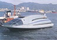
Early next year, the Japan Foundation for Shipbuilding Advancement plans to launch a 100-foot-long, prototype MHD-powered ship that will carry up to 10 people. The test is a sea trial for commercial operations.
And the Argonne lab is spearheading a military-sponsored program that centers on a 21-foot-long, 180-ton monster superconducting magnet. Its trials, confined to the laboratory, are to begin early next year. In a different project, the Navy is considering sea trials for MHD propulsion.
''The marriage of an MHD propulsion system to underwater vehicles is a natural,'' said Dr. Daniel W. Swallom, who manages the Navy-financed program on the propulsion system at the Avco Research Laboratory in Everett, Mass. His program's goal is an open-ocean test with a remotely piloted vehicle.
The Soviet Union has carried out much basic research on this form of propulsion, but intelligence experts are at odds on whether the Russians are applying the idea to their submarines.
Magnetohydrodynamics involves magnetic fields (magneto) and fluids (hydro) that conduct electricity and interact (dynamics). The phenomenon occurs naturally in the Earth's core, giving rise to the planet's magnetic field.
In MHD propulsion, a pair of electrodes on either side of the thruster pass an electric current through sea water. The process does not work effectively with fresh water because it can carry little current. At a right angle to the current is the magnetic field generated by the superconducting magnet. The interaction of the magnetic field and the current produces a strong force on the water, moving it through the duct in the center of the magnet. If the polarity of the current is reversed, so is the direction of thrust.
The action is identical to what happens with an electric motor when its magnetic field crosses a bundle of copper wires carrying an electric current, causing it to move and the central shaft of the motor to rotate.
The
activity in each case revolves around charged particles. In
the motor, the current-filled wires are filled with moving
electrons, which carry a negative charge, and are strongly
acted upon by the magnetic field. In MHD propulsion, the
electric current flowing through the seawater causes the
formation of charged particles, or ions, which in a similar
manner
are acted upon by the powerful field of the
superconducting magnet. It propels both the ions and the
seawater.
The direction of the force is at right angles to the matrix formed by the current and magnetic field. This effect, known as the Lorentz force, was first quantified by the Dutch physicist Hendrik Antoon Lorentz in the late 19th century.
'The Same Old Story'
This form of propulsion was conceived and tested in the United States more than two decades ago but languished until the advent of superconducting magnets. These can be made very powerful and very efficient because, when their coils are cooled almost to absolute zero, they lose no electricity to resistance.
In the late 1980's, Japan became the first nation to publicly embark on a sizable program meant to achieve MHD propulsion. ''It's the same old story,'' said Dr. Petrick at Argonne. ''The idea evolves in this country but someone else picks it up and runs with it.''
Leading the Japanese work is the Foundation for Shipbuilding Advancement, a private concern working with Mitsubishi Heavy Industries, Hitachi Zosen and Mitsui Engineering and Shipbuilding. The foundation is believed to have spent about $31 million on the research since 1987.
''They've gotten the best people from industry, government and the universities to work on this thing,'' said William J. Andahazy, a staffer on the House Armed Services Committee who was once associated with the American MHD effort.
The
Japanese work focuses on the 100-foot ship, whose top speed is
to be eight knots. It has two MHD thrusters on two huge fins
protruding from the craft's hull, according to a paper by the
foundation. A thruster is made up of six magnetic modules,
each fitted with a sea-water duct some 10 inches in diameter.
One thruster assembly is being built by Mitsubishi
Heavy Industries, and the other, with a
slightly different configuration, by the Toshiba Corporation.
A $12 Million Magnet
The Japanese ship is simply a technology test, its small thrusters being relatively inefficient. If the technique is to work commercially, magnets must become lighter, larger and more powerful.
The Japanese work has helped increase American interest in MHD propulsion, although the Defense Department had been studying it for many years. At Argonne, a $4 million program seeking potential Navy applications is under way sponsored by the Pentagon's Defense Advanced Research Projects Agency.
The centerpiece of the lab's work is a huge $12 million superconducting magnet originally built for research on super-efficient generation of electricity from coal. The program's funds were cut, so the giant magnet was never used. Argonne is adapting the behemoth to search for subtle troubles that might complicate the MHD process for large volumes of water.
The big magnet's water channel, 20 inches in diameter, will speed 25,000 gallons of water per minute through a 75-foot closed loop, giving researchers their first clues about the feasibility of full-scale MHD propulsion. If no show-stoppers crop up, the next challenge will be engineering, mainly making heavy superconducting magnets much lighter and more powerful.
''Because
the conductivity of sea water is so low, you have to go to
very large sizes on the thruster, with big superconducting
magnets,'' said Argonne's Dr. Petrick. ''They have to be
lightweight. All that's going to require almost a
breakthrough.'' The problem is that superconducting magnets
are so strong they literally try to tear themselves apart.
Intense magnetic fields cause tiny movements of internal parts
and coils, in turn generating heat that can trigger the
violent loss of superconductivity. To solve the problem,
magnet designers use heavy metal fixtures to inhibit
movement.
For ships and submarines, said Dr. Petrick, the new generation of super-strong, super-light composite materials would have to be applied to the making of superconducting magnets. ''Theoretically, you can exceed the efficiencies of propellers,'' he said.
An 'Acoustic Signature'
Even at low efficiencies, MHD propulsion may be attractive to the military because of its relative silence. Much tracking of enemy submarines centers on listening for the sounds generated by complex power trains and propellers.
MHD propulsion, notes a recent statement from the Navy's David Taylor Research Center in Annapolis, Md., ''offers the potential for an extremely quiet system for propelling underwater vehicles.''
Potential problems from the Navy's point of view include hydrogen bubbles given off at the system's electrode from the electrolysis, or breaking into component parts, of sea water. The bubbles, according to the Taylor statement, ''have an acoustic signature and may produce a visible wake.'' Potential solutions, it said, include gasless electrodes and bubble capture.
Another potential hurdle is a magnetic ''signature,'' or detectable signal. This might be reduced by special magnet designs or shielding.
Hopeful of solutions, the Navy is now building a $1.2 million facility in Newport, R.I., to study the use of superconducting magnets in undersea propulsion. MHD, said the Taylor statement, ''could provide a revolutionary new propulsion system for underwater vehicles in the next century.''
Intelligence
experts are divided on where the Soviets stand in the
propulsion field. The Russians have published many scientific
papers on the topic
and have pioneered all kinds of MHD
technology.
Some
experts say the Soviets have even been trying it at sea,
noting the long pods atop the vertical rudder of all
first-rank Soviets nuclear attack submarines. However, other
experts disparage such analysis, saying the pods are probably
for stowing sensors that can be towed behind the submarines.
Soviet MHD propulsion, they say, can only be found in
fictional
exploits such as ''The Hunt for Red October.''
http://tesladownunder.com/Magnetohydrodynamics.htm
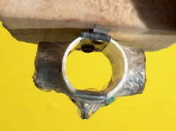
Magnetohydrodynamics
2004, 2005
This is an electrical propulsion method with no moving parts
which applies to any conductive fluid including water, liquid
metal or plasma. Here I am demonstrating the principle with
water. Essentially two electrodes in water have a
current passed between them in a magnetic field and the water
is forced out the back creating thrust. It is not really
a commercial proposition but was featured in "The Hunt for Red
October" as the Soviet stealth sub.
In my model there are two 1 inch NIB magnets about an inch apart. At right angles to this are two electrodes which pass about 1.6 A 9.6 VDC in salt water. ie about 15 watts. Power is by a model car NiCd pack. The whole decidedly unseaworthy construction is made of Balsa and is about 8 inches long.
Performance is underwhelming and I would guess at 1cm/sec boat speed.
Using off board power of 1kW (100V 10A) there is a lot more action and production of hydrogen and ?oxygen or chlorine bubbles streaming from the stern, but I don't have a big enough tub of saltwater to test it for speed. On the right is the ignition of the hydrogen bubbles with the bright yellow flame from the sodium in the seawater bubbles. Normally a hydrogen flame is almost colourless. After a short while the electrodes wear away and the water fills with debris, presumably insoluble salts of the metal electrodes.
The 2005 model is now here! Features: 2.5 times the power (16 alkaline AA cells giving 24V - previously 9.6V NiCd pack) Typically 50W output from salt water swimming pool (20V 2.5A) through to near saturated salt solution (12V 4.5A.) Vertical twin magnets to avoid compass rotation effects and now one magnet is within the hull hence reduced friction. Heavy Aluminium electrodes more completely contained in the magnetic field. It's red hence should go three times as fast.
Small print. It's still incredibly slow. Handles like a brick. It's still no use to anyone. Full sea trials yet to be conducted
For the 4HV discussion on MHD and upcoming competition: http://old.4hv.org/index.php?board=4;action=display;threadid=1287;start=0
For more information try this site: http://www.physics.ubc.ca/outreach/phys420/p420_96/reg/main.htm
I have finally found the description of the Japanese MHD boat, the "Yamoto" made by Mitsubishi in the 1990's and weighing 185 tons which travelled at 15 km/h. It uses a superconducting 4 Tesla magnet, and the round cross section of the motor looks remarkably like mine but about 10 times the diameter (260mm). Electrodes are Titanium with anode coating of DSA (?) and the cathode plated with Platinum. The length of electrodes is 3.4 m. Fascinating article with lots of diagrams.
http://www.physics.ubc.ca/outreach/phys420/p420_96/reg/main.htm
Magnetohydrodynamics and the Lorentz Force Law
By
Reg Milley ( U.B.C )
Magnetohydrodynamics is a subject that concerns itself with several branches of fundamental physics, in particular electricity and magnetism, and thus makes a good demonstration for the senior high school years. Magnetohydrodynamics, or MHD for short, is an application of the Lorentz Force Law which can be used to propel boats and such in an ionic solution, such as salty sea water.
This type of propulsion unit is still being considered as an efficient mode of transportation by some industries of the world however there are still some major engineering problems to overcome. For example the average magnetic field strength to propel a freighter would have to be in the order of 8 to 20 teslas (a fridge magnet, that you would find in your home, is only about 0.01 tesla!). A way to overcoming this particular problem is through the use of high temperature superconducting magnets.
This presentation will be primarily concerned with the theory behind the operation of a magnetohydrodynamic propulsion mechanism that will propel a model boat in a pool of salt water. The static display and the converted model boat are a relatively inexpensive way to demonstrate some fundamental theories of electricity and magnetism. The total cost should not exceed the 200 dollar mark (depending on the resources available to you). The presentation itself might have some added demonstrations involving the relationship between electricity and magnetism (for example to make an electromagnet out of a nail and some copper wire.), but in general the core presentation is to explain, at a senior high school level, the concept of magnetohydrodynamics.
There exists at least one other design for a MHD powered boat of this nature which might be a good reference for any students interested in building one for themselves:
Selfpowered Magnetohydrodynamic Motors, by Stanislaw Bednarek. Found in the American Journal of Physics, Volume 64, No. 1, January 1996.
The basic structure of the MHD mechanism is schematically represented in Figure 1. The two electrodes and two magnets are placed in a salt water solution (preferably saturated) so that the magnetic field is perpendicular to the current flowing through the water. The ions in the water will be attracted to their respective electrodes (opposite charges attract) creating a situation where the Lorentz force law can be applied.
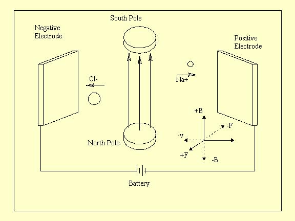
This schematic diagram can be used to find the direction of the force on the charged sodium and chlorine ions. To do this you can use the right hand rule directly, however remember that the right hand rule described here only applies to POSITIVELY charged particles. To fully understand how to apply the right hand rule to negatively charged particles you need to go into the concept of VECTOR CROSS PRODUCTS which is beyond the scope of this presentation ie: not covered in grade 12 physics.
A better way to figure out the direction of the force is to construct a set of axes, as shown in fig.1, and use the scalar equation of the Lorentz force law
To construct the axis you need the right hand rule. The positive velocity direction is in the direction of conventional current ie: the direction of the positive charge flow (+ to -). All the other positive axes follows from the right hand rule (Thumb in + v direction ...).
Now using F = QvB you ignore the actual numbers of Q, v, B (since they would be difficult to measure) and work with the SIGNS of the numbers. In the cases of v and B, the signs correspond to the respective DIRECTIONS of v and B according to the axes you just set up. For Q the sign corresponds to whether the particle is positively charged or negatively charged (in this case Na+ or Cl-). Thus the sign of the resultant force is just found by multiplying all the signs together, according to F = QvB, and the direction is found from the axes you constructed.
For example refer to
fig.1 and take Cl- :
# The sign of Q is -
# The sign of v is -
# The sign of B is +
Therefore two negatives and a positive all multiplied together gives a positive and so the force on the chlorine ion is in the positive F direction which is out of the page. The same can be done for the sodium ion and the resultant force is in the same direction.
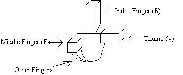
Right Hand Rule
Lorentz Force Law
The Lorentz Force Law can be used to describe the effects of a charged particle moving in a constant magnetic field. The simplest form of this law is given by the scalar equation
F = QvB
# F is the force acting on the particle (vector)
# v is velocity of particle (vector)
# Q is charge of particle (scalar)
B is magnetic field (vector)
NOTE: this case is for v and B perpendicular to each other otherwise use F = QvB(sin(x)) where x is the angle between v and B. When v and B are perpendicular x=90 deg. so sin(x)=1.
The right hand rule comes into play here to figure out which way the force is acting.
Right Hand Rule
For a POSITIVLY
charged particle moving (velocity v) in a magnetic field
(field B) the direction of the resultant force (force F) can
be found by:
# 1) THUMB of right hand in direction of VELOCITY, v (first
vector)
# 2) INDEX FINGER of r.h. in direction of FIELD, B (second
vector)
# 3) Your PALM (or middle finger if you like) now points in
the direction of the FORCE, F (final vector)
The force will ALWAYS be perpendicular to the PLANE of the vectors v and B, no matter what the angle between v and B is. Just pretend the following picture is of your right hand:
Calculating the Magnitude of the Force
Once you have found
the direction of the force you need to calculate its
MAGNITUDE. You can't directly use the standard form of the
Lorentz force law since the values of Q, v and B would be very
difficult to measure. So you have to convert the equation in
terms of things which are easily measured:
Start with F = QvB
# I = Q / t (definition of current) therefore Q = I t
# v = d / t (definition of velocity)
# substitute to get
F = (I t)(d / t)B
simplify...
F = IdB
# I is the current of charges
# d is the distance traveled by the charges
# B is the magnetic field (perpendicular to the direction of
the current)
The boat itself needs a reasonable force to accelerate it. The following calculations are based on my construction of the boat.
Use F = I d B
I = 3 A (short circuit current between electrodes)
d = 2.7 cm (0.027 m) (distance between electrodes)
B = 0.2 T ( S.I. units: 0.2 N/(A*m) measured)
therefore force on water (force propelling the boat) is:
F = (3.0 A)(0.027
m)(0.2 N/(A*m))
F = 0.0162 Newtons
It is only natural that students in grade 12 physics don't have an intuitive idea of how much this force actually is, so to put things into perspective you ask the question:
what mass would this
be if the force is due to gravity acting on that mass?
# F = ma = mg therefore m = F / g
# F = 0.0162 N ; g = 9.8 m/s2
# m = (0.0162 kg*m/s2) / (9.8 m/s2) = 1.6 grams
# is about the mass of a penny.
What acceleration does this produce on the boat?
Boat has mass 0.470 kg
F = ma therefore a = F/m = (0.0162N)/(0.47kg) = 0.04 m/ s2
What speed will the boat be going after 30 s?
a = v/t therefore v = at = (0.04m/s2)(30s) = 0.0012 m/s = 1.2 mm/s
Not fast but still noticeable!
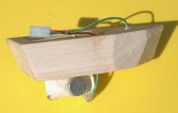
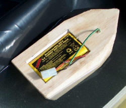
The Motor
This section contains pictures and descriptions of the MHD motor, static display and boat which I used in my presentation.
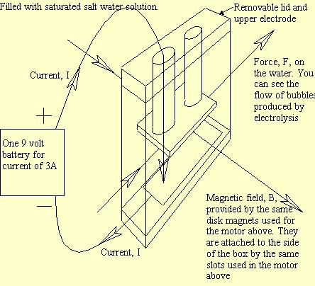
Firstly, you need to see how many batteries you need to carry on the boat. By experimentation and calculation it was found that the force produced by a current of 3A, supplied by a 9 volt battery, would do nicely. Is 9 volts enough to produce this current in a saturated salt water solution?
# Use R = d/(A) where d is the distance the current travels
A is the cross sectional area of the material in which the current is traveling
is the conductivity of the material
In this case the
material is a saturated salt water solution and:
# d = 0.04 m is the distance between the electrodes
# A = 0.0008 m2 is the area of an electrode = 22.6 (m)-1 for
saturated salt water at 20 deg. Celsius
# Carrying the calculation through to get R = 2.21 . Now use
Ohms Law: V = IR where I = 3A (short-circuit current of a 9
volt battery) V = 6.64 volts So a 9 volt battery should do the
job.
If the water is not saturated, which was the case with my project, you might want to put some more batteries in series. (I had 3 in series; on the heavy side)
Static Display