
rexresearch
A
device consisting of a giant rubber tube may hold the key to
producing affordable electricity from the energy in sea waves.
Invented in the UK, the 'Anaconda' is a totally innovative wave
energy concept. Its ultra-simple design means it would be cheap
to manufacture and maintain, enabling it to produce clean
electricity at lower cost than other types of wave energy
converter. Cost has been a key barrier to deployment of such
converters to date.
Named after the snake of the same name because of its long thin shape, the Anaconda is closed at both ends and filled completely with water. It is designed to be anchored just below the sea's surface, with one end facing the oncoming waves.
A wave hitting the end squeezes it and causes a 'bulge wave'* to form inside the tube. As the bulge wave runs through the tube, the initial sea wave that caused it runs along the outside of the tube at the same speed, squeezing the tube more and more and causing the bulge wave to get bigger and bigger. The bulge wave then turns a turbine fitted at the far end of the device and the power produced is fed to shore via a cable.
Because it is made of rubber, the Anaconda is much lighter than other wave energy devices (which are primarily made of metal) and dispenses with the need for hydraulic rams, hinges and articulated joints. This reduces capital and maintenance costs and scope for breakdowns.
The Anaconda is, however, still at an early stage of development. The concept has only been proven at very small laboratory-scale, so important questions about its potential performance still need to be answered. Funded by the Engineering and Physical Sciences Research Council (EPSRC), and in collaboration with the Anaconda's inventors and with its developer (Checkmate SeaEnergy), engineers at the University of Southampton are now embarking on a programme of larger-scale laboratory experiments and novel mathematical studies designed to do just that.
Using tubes with diameters of 0.25 and 0.5 metres, the experiments will assess the Anaconda's behaviour in regular, irregular and extreme waves. Parameters measured will include internal pressures, changes in tube shape and the forces that mooring cables would be subjected to. As well as providing insights into the device's hydrodynamic behaviour, the data will form the basis of a mathematical model that can estimate exactly how much power a full-scale Anaconda would produce.
When built, each full-scale Anaconda device would be 200 metres long and 7 metres in diameter, and deployed in water depths of between 40 and 100 metres. Initial assessments indicate that the Anaconda would be rated at a power output of 1MW (roughly the electricity consumption of 2000 houses) and might be able to generate power at a cost of 6p per kWh or less. Although around twice as much as the cost of electricity generated from traditional coal-fired power stations, this compares very favourably with generation costs for other leading wave energy concepts.
"The Anaconda could make a valuable contribution to environmental protection by encouraging the use of wave power," says Professor John Chaplin, who is leading the EPSRC-funded project. "A one-third scale model of the Anaconda could be built next year for sea testing and we could see the first full-size device deployed off the UK coast in around five years' time."
The Anaconda was invented by Francis Farley (an experimental physicist) and Rod Rainey (of Atkins Oil and Gas). There may be advantages in making part of the tube inelastic, but this is still under assessment.
Wave-generated electricity is carbon-free and so can help the fight against global warming. Together with tidal energy, it is estimated that wave power could supply up to 20% of the UK's current electricity demand.
The two-year project 'The Hydrodynamics of a Distensible Wave Energy Converter' is receiving EPSRC funding of just over £430,000.
*A bulge wave is a wave of pressure produced when a fluid
oscillates forwards and backwards inside a tube.
Abstract -- A generally horizontal distensible (elastically
flexible) tube 1 in the sea containing water and oriented in
the direction of wave travel with distensibility such that the
propagation velocity of pressure waves inside the tube
(referred to as bulge waves) is the same as the velocity of
propagation of the waves in the sea outside. Energy is then
transferred from the ocean waves to the bulge wave. Energy
extraction means at the stem and/or bow deliver useful energy.
Said energy extraction means may comprise pistons actuating
pumps or linear or rotating generators, or may comprise
one-way valves with the effect that water is pumped into a
pressure system or into the distensible tube. In a preferred
embodiment one-way valves at or near the stern admit water to
the tube which flows out at the bow through a water turbine
driving an electric generator. The tube may be suspended below
the surface from floats 4, or may be supported on the sea bed
(figure 2).
The
invention relates to an apparatus for extracting useful energy
from the waves of the sea.
James Lighthill in reference [1]
shows how pressure waves can propagate along a distensible
tube. The pressure causes the tube to dilate locally and this
reduces the velocity of propagation.
The more distensible the tube,
the slower is the wave velocity. It is convenient to refer to
these waves in the tube as "bulge waves". Lighthili applies
his analysis to blood flow in arteries.
This invention, on a much larger
scale, applies the same principle to extract energy from ocean
waves. A long distensible tube full of water is oriented in
the direction of wave propagation and the velocity of the
bulge wave inside the tube is more or less equal to the
velocity of the ocean waves outside. In this case energy is
transferred from the ocean to the bulge wave which grows along
the length of the tube. At the end of the tube a piston or
other means is used to capture the energy of the bulge wave
and generate useful power.
Many prior wave energy inventions
use flexible membranes and/or tubes oriented in the direction
of wave travel, but none appear to rely on the distensibility
of a tube made (or partly made) of an elastic material, as a
means of storing wave energy prior to conversion. The novelty
of this invention is the use of a tube with elastic walls
carrying bulge waves matched to the velocity of the ocean
waves.
Definitions Elastic: A substance,
material or object is elastic if it can be deformed by an
applied force and return to its original shape when the force
is removed. An elastic object obeys Hooke's law that the
strain produced is substantially proportional to the applied
stress. All solid materials are more or less elastic up to
some limiting strain. For example the limiting strain for
steel is about 0.1% while for rubber the limiting strain may
be around 50%. By highly elastic we mean a substance, material
or object for which the limiting strain is greater than 5%.
The elasticity of an object depends upon its shape as well as
the material from which it is made. Thus a helical spring made
of steel can be highly elastic in the direction of its
principal axis, although the' steel itself is not.
Distensible: A tube is
distensible if it responds to changes of internal pressure
with a proportional change of its cross-sectional area from
its undisturbed value. Distensible tubes have highly elastic
walls, either because they are made of elastic material or
because they are in some way folded or corrugated. For a tube
of cross-sectional area S with internal pressure p, the
distensibility is defined as D = (uS) dS/dp (1).
It is important for this
invention to distinguish between distensibility and
flexibility: some examples may make this clear. A motor car
tyre is flexible but not distensible: when inflated it is
elastic for small deformations. The inner tube of the motor
car tyre is distensible. An inflatable boat is flexible but
not distensible: its size does not vary with the inflation
pressure.
This is because inflatable boats
are made of reinforced elastomeric sheet which is flexible but
not highly elastic.
Bulge wave: As described by
Lighthill in reference [1], in a distensible tube a
longitudinal pressure wave, associated with a change of
cross-section and a longitudinal fluid velocity, can propagate
along the tube. This wave is called a bulge wave. The velocity
of propagation of the bulge wave is c where c2 = 1/(pD), p is
the density of the fluid inside and D the distensibility as
defined above in equation (1).
Bow and stern: For a long object
in the sea oriented generally in the direction of wave
propagation, the end facing into the waves will be referred to
as the bow: the other end facing in the direction of
propagation will be referred to as the stem.
The invention According to this
invention in its first characteristic the wave energy
converter comprises a long distensible tube, generally
horizontal, immersed or partially immersed in the sea and
oriented generally in the direction of wave propagation, said
tube being open or closed at the bow and furnished with energy
extraction means at one or both ends, the distensibility of
the tube being chosen so that the velocity of the bulge wave
along the tube is generally equal to or close to the velocity
of the waves in the surrounding sea.
The tube is filled with water or
other liquid of similar density which may with advantage be at
a pressure higher than that in the surrounding sea.
According to the invention the
cross-section of the distensible tube may be of any shape and
the elasticity of the walls may vary around the circumference,
part of the circumference in some embodiments being
substantially inelastic. Furthermore the shape, size and
elasticity of the cross-section, and consequentially the
distensibility, may with advantage vary along the length of
the tube.
According to the invention in its
second characteristic the walls of said tube may be comprised
of any highly elastic material such as natural or synthetic
rubber with or without fibre reinforcement or a highly elastic
arrangement of less elastic substances such as helical
springs, corrugated metal or a reticulated structure of
flexible membranes inflated with compressed air or other
fluid.
According to the invention in its
third characteristic the energy extraction means at the ends
of the tube may compnse any machinery or process which is
driven by the oscillating pressure and oscillating
longitudinal velocity inside the tube, for example without
limitation one or more turbines or pistons operating at any
angle to the horizontal actuated by the water pressure inside
said tube and driving hydraulic pumps or linear or rotating
generators, or overtopping means allowing water inside the
tube to be driven over a weir or through one or more
non-return valves into a reservoir at elevated pressure, a
separate non-return valve allowing water to enter the tube
from the sea when the pressure inside is low, or any
combination of the above.
In an alternative embodiment the
energy extraction means comprises a vertical tube containing
water with means for adjusting the height of the water surface
and with a piston moving more or less vertically. In a further
alternative the vertical tube is closed at the top except for
a hole furnished with a float valve which allows air to escape
but not water and is further furnished with a non-return valve
leading to a hydraulic accumulator, with the effect that when
the water inside the tube reaches the top of the tube the
float valve closes and water is driven at high pressure into
said hydraulic accumulator.
According to the invention in its
fourth characteristic the distensible tube may be located on
the sea bed, fixed in position by conventional attachments
according to the art or ballasted with liquid or solid ballast
so as to sink to the sea bed. Alternatively the tube may be
fixed at some distance below the sea surface by attachment to
a supporting frame attached to the sea bed. In another
embodiment the distensible tube may be furnished with buoyancy
means the whole being ballasted to float with said tube partly
or wholly submerged. In this case the tube is held in position
with moorings according to the art.
Some
specific embodiments of the invention will now be described by
way of example with reference to the accompanying drawings in
which:
Figure 1 shows in side
elevation and in lateral cross-section a distensible tube
furnished with buoyancy chambers floating close to the water
surface;

Figure 2 shows in side
elevation a distensible tube ballasted to rest on the sea
floor;
Figure 3 shows a vanety of
possible cross-sections of the distensible tube;

Figure 4 shows the
cross-section of a distensible tube with inflated reticulated
walls;

Figure 5 shows in lateral
longitudinal section extraction means comprising a piston
moving horizontally and driving a hydraulic pump;
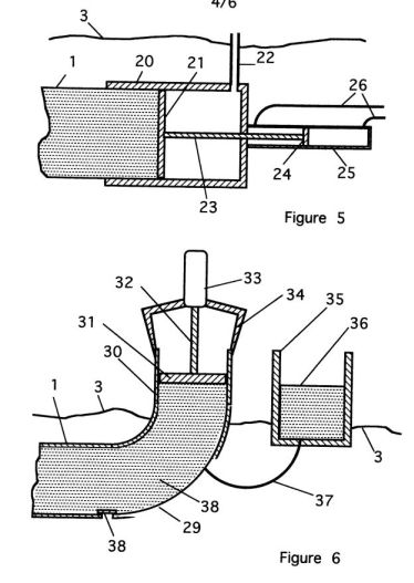
Figure 6 shows in lateral
longitudinal section energy extraction means comprising a
piston moving vertically and driving a hydraulic pump;
Figure 7 shows in lateral longitudinal section energy
extraction means comprising a hydraulic ram pump driving water
at high pressure into a hydraulic accumulator;

Figure 8 shows in lateral
longitudinal section energy extraction means comprising a
transition to a narrow rigid pipe which carries high pressure
water ashore;
Figure 9 shows in lateral
longitudinal section energy extraction means comprising a
one-way valve at the stern of the tube and a turbine at the
bow driving an electric generator;

Figure 9 shows in lateral
longitudinal section energy extraction means comprising a
one-way valve at the stern of the tube and a turbine at the
bow driving an electric generator;
Figure 10 shows in
lateral longitudinal section an improved one-way valve system
which may be used with the turbine and electric generator
illustrated in Figure 9;
Figure 11 shows in section
an energy converter comprising two distensible vessels
connected by a substantially rigid pipe.
Particular
embodiments of the invention will now be described by way of
example with reference to the figures. Figure 1 illustrates by
way of example in side elevation a long distensible tube 1
with rigid bow 2 furnished with a multiplicity of hollow
buoyant chambers 4 with the effect that the apparatus floats
with the tube 1 more or less horizontal and slightly below the
sea surface 3. The device is held in position by moorings 7
according to the art. The walls of the tube 1 are highly
elastic and made for example of natural or synthetic rubber as
illustrated in the cross-section view AA in Figure 1. The high
elasticity of the walls has the effect of making the tube 1
distensible, the said elasticity being chosen so that the
velocity of the bulge wave propagating inside the tube is
close to the velocity of the waves in the sea outside.
At the stern and/or bow the tube
is furnished with energy extraction means 5 of which there are
many alternative embodiments which will be described in detail
below.
The operation of the device is as
follows. The oscillating pressure and pressure gradient
outside the Lube wall due to the ocean waves excites a bulge
wave near the bow which propagates along the tube at the bulge
wave velocity. As the bulge wave moves along the tube, the
ocean wave is moving along the tube at the same speed and at
each point contributes a further increase in pressure. The
result is a cumulative more or less linear increase in the
amplitude of the bulge wave, which in effect progressively
sucks energy in from the wave. Depending on its length, the
oscillating internal pressure amplitude at the end of the tube
can be 3-5 times the amplitude of the oscillating pressure in
the ocean wave. Useful energy is then extracted from the
oscillating pressure at the end of the tube, as explained in
detail below. In a typical case the amplitude of the bulge
wave at the stern of the tube 1 is such that the tube must
expand and contract by about 50% in cross-sectional area from
its undisturbed value.
In an alternative embodiment,
illustrated in side elevation in Figure 2, the distensible tube 1 is furnished
on its lower surface with a multiplicity of flexible bags 8
filled with ballast means, for example without limitation
sand, gravel or liquid mud, with the effect that the tube 1 is
held firmly on the sea bed 9. It may be further located by
means of moorings 7. In a preferred embodiment the flexible
bags 8 may be joined together to comprise one long bag with
the same effect. This embodiment is useful in shallow water
such that the ocean waves on the sea surface 3 produce a
significant pressure oscillation at the depth of the
distensible tube 1, exciting a bulge wave as explained above.
The tube is furnished at the stern with energy extraction
means 5 of which there are many alternative embodiments which
will be described in detail below. The operation of the device
is similar to that described above.
Figure
3 illustrates in cross-section by way of example a
variety of constructions which may be adopted for the
distensible tube. The cross-section may be of any shape. To
achieve the large changes in cross-sectional area mentioned
above, all or part of the circumference of the tube must be
highly elastic. Figure 3a illustrates an embodiment in which
the walls of the tube 10 are made of natural or synthetic
rubber, the elasticity of the walls being chosen to achieve
the correct distensibility as specified above. The elasticity
of the walls need not be the same at all points of the
circumference. Figure 3b
illustrates by way of example an embodiment in which the lower
side of the tube is a substantially inelastic plate 11, while
the rest of the circumference lOis highly elastic. Figure 3c illustrates a
construction in which the sides of the tube 10 are elastic but
the top and bottom 11 comprise inelastic plates. In a further
alternative, illustrated in Figure
3d, the top and bottom 11 of the tube are inelastic
but the sides of the tube 12 are corrugated; in this case the
tube can expand and contract vertically like a conventional
metal bellows, and the distensibility is controlled by the
vertical spring constant of the corrugated walls. Figure 3e illustrates an
embodiment in which the whole circumference of the
cross-section is corrugated, the distensibility being
controlled by the circumferential spring constant of the
walls. There can be any number of corrugations. Figure 3f
illustrates an embodiment in which the cross-section is
normally elliptical, but can expand out to a more circular
shape with greater cross-sectional area by the bending of the
walls, which are effectively corrugated as in Figure 3e, but
with only two corrugations.
In a preferred embodiment
illustrated in transverse cross-section in Figure 4a the walls
of the tube compnse a reticulated structure of flexible
membranes, inflated by compressed air or other fluid,
according to the art of inflated structures. Said membranes
may be themselves highly elastic or alternatively
fibre-reinforced elastomenc sheets with limited elasticity.
Although the flexible membranes comprising a structure may be
themselves substantially inelastic, an inflated structure can
be highly elastic: well known examples are a motor car tyre
and a football. The principles are illustrated in Figures 4b
and 4c which show part of an inflated structure comprising a
multiplicity of similar cells joined together in a linear
array. When the cells are inflated with compressed air the
upper and lower membranes adopt the shape that maximizes the
volume of the cell; this is achieved when the upper and lower
membranes lie on the circle circumscribing the corner points
16, 17, 18 and 19. This circle is shown by dotted lines in
Figure 4b. It will be seen that in Figure 4b the upper and
lower membranes become rather flat, with the result that in
this case the structure is not significantly elastic in the
horizontal direction.
In Figure 4c however the internal
vertical membranes are shorter, with the effect that the upper
and lower membranes, which again follow the shape of the
circumscribing circle, are substantially curved. It results
that the structure is highly elastic in the horizontal
direction. The effective modulus of elasticity of the
structure can be varied by changing the pressure inside the
cells.
In the embodiment of the
distensible tube illustrated in transverse cross-section in
Figure 4a, the dimensions of the cells are so chosen that the
inner and outer membranes are highly curved with the effect
that the wall of the enclosed hollow tube is highly elastic in
the circumferential direction and the distensibility of the
tube is large. The distensibility of the tube can be varied by
changing the inflation pressure of the wall with the effect
that the velocity of the bulge wave inside the tube can easily
be adjusted from time to time to match the prevailing wave
conditions.
This is a major advantage of this
embodiment for wave energy conversion. In some embodiments the
walls of the distensible tube may be made of a highly elastic
material such as natural or synthetic rubber said walls
further comprising internal spaces which may be inflated with
air or other fluid with the effect that the distensibility of
the tube may be adjusted from time to time.
In all the embodiments
illustrated in Figures 3 and 4, the cross-section of the tube
may be the same at all longitudinal positions along the tube.
Or with advantage the dimensions or the circumferential
elasticity of the cross-section may vary along the tube.
Particular embodiments of the
energy extraction means mounted at the stem of the distensible
tube will now be described with reference to Figures 5 to 10.
In the embodiment illustrated by way of example in Figure 5 a
rigid cylindrical tube 20 is attached to the distensible tube
1 at its stern end. The piston 21 slides inside the rigid tube
20 and via a connecting rod 23 drives a conventional hydraulic
pump 25 which delivers hydraulic fluid which may be oil, air
or water to a useful output via the connecting pipes 26. The
space behind the piston 21 is with advantage filled with air
and vented to the atmosphere via tube 22. In operation the
bulge wave propagating along the distensible tube 1 builds up
to a large amplitude as it reaches the stem.
The oscillating pressure in the
bulge wave drives the piston to and fro with the effect that
the said hydraulic fluid is pumped under pressure to a useful
output.
Another embodiment of the energy
extraction means is illustrated by way of example in Figure 6.
In this embodiment the distensible tube 1 is tenninated at the
stern with a bent tube 29 connected to a rigid cylinder 30
with piston 31 A hydraulic pump 33 is supported for example on
an open framework 34 and connected to the piston by means of
the connecting rod 32. A reservoir 35 contains water 36 and
the water level is maintain above the mean level of the sea by
auxiliary pumps (not illustrated). This reservoir is connected
to the energy extraction means by a nan-ow pipe with the
effect that the mean water level in the cylinder 30 is
maintained substantially above the level of the sea but the
pipe is too narrow to pass the bulge wave pressure
oscillations to the reservoir. The piston 31 is buoyant and on
average floats on the water in the cylinder 30. The rising and
falling of the water level in the cylinder 30 under the action
of the bulge wave drives the piston to and fro vertically with
the effect that useful hydraulic energy is generated by the
hydraulic pump 33 and passed to a useful output via connecting
pipes (not illustrated) according to the art. In this
embodiment, if the wave energy is very high so that the bulge
wave is exceptionally large, the piston 31 will rise above the
end of the cylinder 30 and water will spill out of the
cylinder into the surrounding sea with the effect of relieving
the excess pressure in the system and protecting it from
damage. The piston will fall back into the cylinder and the
lost water will be replaced by water from the reservoir via
the pipe 37. If the bulge wave oscillation is of large
amplitude the pressure inside the distensible tube may fall
below the sea water pressure outside with the effect that the
walls of the distensible tube could collapse inwards. To avoid
this, the tube may with advantage be furnished with a one-way
valve 38 which allows sea water to enter the tube if the
pressure inside is lower than outside.
Another embodiment of the energy
extraction means is illustrated by way of example in Figure 7.
In this embodiment the distensible tube 1 is terminated at the
stern by a bend connected to a vertical tube 42. Which is
closed at the top close to sea level by a bulkhead 43. Said
bulkhead is furnished with a hole 44 fitted with a float valve
45 with the effect that air can flow freely in and out of the
tube 42 but water cannot escape. The bulkhead is further
furnished with a one-way valve 46 leading to a hydraulic
accumulator 47 which contains water under pressure according
to the art. In this embodiment the water surface 41 inside the
vertical tube 42 is on average more or less the same as in the
sea outside but is driven up and down through a large
amplitude by the bulge wave inside the tube. As the water
surface 42 rises the air above it is vented to the atmosphere
via the hole 44; but when the water reaches the bulkhead the
float valve closes and a high pressure shock is generated.
This forces some water through the one-way valve 46 into the
hydraulic accumulator 47 with the effect that energy is
captured to the hydraulic accumulator. From the accumulator
sea water under pressure may be led off through the pipe 48 to
do useful work according to the art. The water thus lost from
the tube 42 is replaced from the sea when the pressure in the
bulge wave goes negative via the one-way valve 38
substantially as described above. The overall effect of this
embodiment is that the bulge waves cause sea water to be
pumped at high pressure to a useful output with no moving
parts (apart from the float valve and one-way valves). In this
embodiment the distensible tube 1 may optionally be open to
the sea at the bow.
Another embodiment of the energy
extraction means is illustrated by way of example in Figure 8.
In this embodiment the distensible tube 1 is connected to a
long rigid output pipe 51 by means of an intermediate
transition and matching section 50. Said transition and
matching Section 50 may comprise several stages (not
illustrated) with changes of cross-section and of
distensibility with the effect that the bulge wave with
comparatively small pressure oscillations and with large
longitudinal velocity oscillations is converted without
substantial loss or reflection into a wave with high pressure
oscillations and low velocities, the latter being more
suitable for transmitting energy to shore through a
comparatively narrow pipe.
In the embodiment illustrated by
way of example in longitudinal side elevation in Figure 9 the
distensible tube 1 is furnished at the stern with a partially
distensible end pipe 60 furnished with one or more one-way
valves 61 which allow sea water to enter the pipe but not to
leave.
The tube is further furnished at
the bow with a rigid pipe 62 open to the sea and fitted with
an internal frame 63 which supports an electric generator 65
and water turbine 64. The operation of the system is as
follows. The pressure inside the distensible tube 1 is
generally higher than the pressure outside. But during the low
pressure phase of the bulge wave arriving at the stern, the
pressure in the end pipe 60 is lower than the pressure in the
sea with the effect that water is sucked into said end pipe
through the one-way valve or valves 61. During the high
pressure phase of the bulge wave the one-way valve is closed
and water cannot leave the tube. The result is a net intake of
water at the stern which maintains the high average pressure
in the distensible tube 1 and the result is a more or less
uniform flow of water along the tube from stern to bow.
Said water flows out into the sea
at the bow through the turbine 64 generating electricity
according to the art. A mooring 7 serves to hold the device in
position. With advantage the end pipe 60 may be furnished with
one or more side chambers 66 which may be distensible or rigid
and may contain air. Said side chambers have the effect of
improving the matching of the bulge wave and smoothing the
flow of water to the turbine. In this embodiment the
distensible tube 1 may in addition be furnished with a
multiplicity of one-way valves 68 dispersed along the length
of the tube with the effect of allowing more water to enter
the tube at these positions and enhancing the flow through the
turbine 64.
Figure 10 shows by way of example
in longitudinal lateral cross-section another embodiment of
the one-way valve system which may be attached to the stern of
the distensible tube or at some position along the length of
the tube and used in combination with a turbine at the bow as
described with reference to Figure 9. The purpose of this
embodiment is to increase the pressure inside the distensible
tube 1 with a view to avoiding any tendency of the tube to
collapse inwards. Referring to Figure 10, in this embodiment
the distensible tube 1 is furnished at its stern with a rigid
tube 70 with sliding piston 71 which compresses and expands
the corrugated bellows 73. The high pressure inside the tube 1
is balanced by the helical spring 74. The space 78 inside the
bellows communicates with the interior of the distensible tube
1 through the one-way valve 72 and with the sea via one-way
valve 75, while the space between the bellows and the rigid
tube 70 may with advantage be vented to the atmosphere via the
tube 76. In operation the oscillating pressure in the bulge
wave inside the distensible tube 1 drives the piston 71 to and
fro. When moving to the left in Figure 10 it sucks water from
the sea via one-way valve 75 into the space 78. When moving to
the right it drives the water from space 78 through the
one-way valve 72 into the distensible tube 1. In this
embodiment the distensible tube 1 is furnished at the bow with
a turbine and electric generator substantially as already
illustrated and described in relation to Figure 9 with the
effect that the energy of the waves causes water to be pumped
through the turbine generating useful electricity. Many other
arrangements of pistons may be adopted according to the art
with the effect of pumping water at elevated pressure into the
distensible tube 1. In particular, there may with advantage be
a number of chambers 78, which may be brought into operation
in varying numbers, by locking the one-way valves. In this way
the minimum bulge wave pressure required to move the piston
may be varied, to suit the wave conditions, and other more
complex control strategies adopted.
In an alternative embodiment
similar to Figure 9 but not illustrated, the one-way valve 61
at the stern may be reversed, allowing water to leave the end
pipe 60 but not to enter and a turbine can be located in this
stream of water at the stern. In another alternative instead
of passing through a turbine, the flow of water can be
directed into an elevated reservoir either in the sea or on
land with the effect that water is pumped from the sea to the
reservoir. This may be used for example for flushing out
estuaries or supplying fish farms.
In another embodiment illustrated
by way of example in longitudinal cross-section in Figure 11
two distensible vessels of any shape 80 containing water or
other fluid are connected by a more or less ngid pipe 81 with
the effect that under the action of the waves water flows to
and fro along the pipe between the said vessels. Any energy
extraction means described above may be connected to the
vessels with the effects substantially as already described.
In particular either one or both the vessels may be furnished
with one or more one-way valves 82 or more elaborate one-way
valve systems as illustrated in Figure 10 with the effect that
water is pumped from the sea into the vessels. The vessels may
be further furnished with one or more turbines 83 generating
electric power substantially as already described.
It will be apparent that some
particular features of one of the alternative embodiments
described by way of example above may be combined with
particular features of another embodiment, all within the
scope of the invention.
References [1] James Lighthill,
Waves in Fluids, Cambridge University Press (1978), p. 96 ff
Abstract -- A wave energy converter makes use of pressure waves
(bulge waves) that travel along a generally horizontal
distensible tube 1 in the sea 7. The tube 1 contains water
under pressure and is oriented in the direction of wave
travel. Its flexibility / expandability is such that the
velocity of pressure waves inside the tube is the same as the
velocity of the waves in the sea. The tube 1 has highly
elastic walls incorporating or surrounded by helical
reinforcement members 2. The velocity of the pressure waves
can be tuned to match the wave velocity by regulating the
pressure of the water inside the tube. Energy is then
transferred from the ocean waves to the bulge wave. Energy
extraction means 6 at the end of the tube 1 delivers useful
energy as electricity or high pressure sea water.
The invention is an apparatus for
extracting useful energy from the waves of the sea, and is an
improved embodiment of the invention described in reference
[IJ.
James Lighthill in reference (21
shows how pressure waves can propagate along a distensible
tube. The more distensible the tube, the slower is the wave
velocity. It is convenient to refer to these waves in the tube
as "bulge waves". Lighthill applies his analysis to blood flow
in arteries. This invention, on a much larger scale, applies
the same principle to extract energy from ocean waves. A long
distensible tube full of water is oriented in the direction of
wave propagation and the velocity of the bulge wave inside the
tube is more or less equal to the velocity of the ocean waves
outside. In this case energy is transferred from the ocean to
the bulge wave which grows along the length of the tube. At
the end of the tube a piston or other means is used to capture
the energy of the bulge wave and generate useful power.
Many prior wave energy inventions
use flexible membranes andlor tubes oriented in the direction
of wave travel, but none appear to rely on the distensibility
of a tube made (or partly made) of an elastic material. The
novelty of this invention is the use of a tube with elastic
walls carrying bulge waves matched to the velocity of the
ocean waves. By adding helical reinforcement to the elastic
walls the distensibility of the tube can readily be
controlled.
Elastic tubes reinforced by
helical windings are known to enclose a smaller volume when
stretched by an axial force and have therefore been proposed
as pumping means in wave power converters using the vertical
heaving of floating bodies. In contrast according to this
invention the tube is used at maximum volume, no axial force
is applied to the tube which is immersed in the water and
responds to the lateral pressure exerted directly upon it by
the waves. The propagation of bulge waves in an elastic tube
with helical reinforcement and the application to wave power
conversion are both novel concepts.
Definitions Elastic: A substance,
material or object is elastic if it can be deformed by an
applied force and return to its original shape when the force
is removed. An elastic object obeys Hooke's law that the
strain produced is substantially proportional to the applied
stress. All solid materials are more or less elastic up to
some limiting strain. For example the limiting strain for
steel is about 0.1% while for rubber the limiting strain may
be around 50%. By highly elastic we mean a substance, material
or object for which the limiting strain is greater than 5%.
The elasticity of an object depends upon its shape as well as
the material from which it is made. Thus a helical spring made
of steel can be highly elastic in the direction of its
principal axis, although the steel itself is not.
Distensible: A tube is
distensible if it responds to changes of internal pressure
with a more or less proportional change of its cross-sectional
area from its undisturbed value. Distensible tubes have highly
elastic walls, either because they are made of elastic
material or because they are in some way folded or corrugated.
For a tube of cross-sectional area S with internal pressure p.
the distensibility is defined as D = (1/5) dS/dp (I).
It is important for this
invention to distinguish between distensibility and
flexibility: some examples may make this clear. A motor car
tyre is flexible but not distensible: when inflated it is
elastic for small deformations. The inner tube of the motor
car tyre is distensible. An inflatable boat is flexible but
not distensible: its size does not vary with the inflation
pressure.
This is because inflatable boats
are made of reinforced elastomeric sheet which is flexible but
not highly elastic. A garden hose is flexible but not
distensible. A toy balloon is distensible.
Bulge wave: As described by
Lighthill in reference 12), in a distensible tube a
longitudinal pressure wave, associated with a change of
cross-section and a longitudinal fluid velocity, can propagate
along the tube. This wave is called a bulge wave. The velocity
of propagation of the bulge wave is c where c2 = 1/(pD), p is
the density of the fluid inside and D the distensibility as
defined above in equation (1).
Bow and stern: For a long object
in the sea oriented generally in the direction of wave
propagation, the end facing into the waves will be referred to
as the bow: the other end facing in the direction of
propagation will be referred to as the stern.
Pitch: The pitch of a helix is
the angle between the lines of the helix and the transverse
plane perpendicular to the axis of the helix.
The invention According to this
invention in its first characteristic the wave energy
converter comprises a long distensible tube, generally
horizontal, immersed or partially immersed in the sea and
oriented generally in the direction of wave propagation, said
tube being closed and containing water under pressure and
furnished with energy extraction means at one or both ends,
the distensibility of the tube being adjusted so that the
velocity of the bulge wave along the tube is generally equal
to or close to the velocity of the waves in the surrounding
sea. The tube is of circular cross-section and the diameter
may with advantage vary along the length of the tube.
According to the invention in its
second characteristic the impermeable wall of the tube is
comprised of a highly elastic material such as natural or
synthetic rubber and furnished with a multiplicity of helical
reinforcement means made of any material. Said reinforcement
means may comprise without limitation wires, cables, tapes,
ropes, strings or cords made of substantially inextensible
material such as metal, natural or synthetic fibre or
partially extensible synthetic material such as high modulus
polyethylene, polyester or keviar. Each element of said
reinforcement means is in the form of a helix circumscribing
the tube or embedded in the wall of the tube extending from
one end of the tube to the other and fixed to the tube at each
end. With advantage the helical reinforcement means are
parallel to each other and equally spaced around the
circumference of the tube. Said helices may be right-handed or
left-handed or both and of constant and identical pitch.
Right-handed and left-handed helices may with advantage be
woven together to comprise a reticulate structure or they may
be of different diameters so that one fits inside the other.
According to the invention in its
third characteristic the distensible tube with helical
reinforcement is filled with water connected to pressure
means. Said pressure means ensures that the pressure inside
the tube is maintained and controlled according to the art. It
may comprise for example without limitation a hydraulic
accumulator with elastic walls or a hydraulic accumulator
containing air under pressure or a hydraulic accumulator in
which the contained water is raised vertically or a tube
supplying water under pressure from the shore or from an
auxiliary vessel or structure.
The effect of the pressure inside
the tube is twofold. On the one hand it tends to expand the
tube laterally but, because of the helical reinforcement, this
can only occur if the tube contracts axially. On the other
hand the pressure acting on the ends of the tube tends to
lengthen it axially. If the pitch angle of the helical
reinforcement is close to 35 degrees, these two tendencies
cancel each other and the tube is maintained in stable
equilibrium. If this equilibrium is disturbed, for example by
squeezing the tube in one place, a bulge wave will be
generated and will propagate along the tube. The velocity of
propagation of the bulge wave along the tube is proportional
to the square root of the pressure inside. If the velocity of
the bulge wave is equal to the velocity of propagation of the
waves in the sea, then energy is transferred from the sea to
the bulge wave and a bulge wave of large amplitude arrives at
the stern.
According to the invention in its
fourth characteristic the energy extraction means at the ends
of the tube may comprise any machinery or process which is
driven by the oscillating pressure and oscillating
longitudinal velocity inside the tube and produces useful
hydraulic or electrical energy, for example without limitation
one or more turbines or pistons operating at any angle to the
horizontal actuated by the water pressure inside said tube and
driving hydraulic pumps or linear or rotating electric
generators, or overtopping means allowing water inside the
tube to be driven over a weir or through one or more
non-return valves into a reservoir at elevated pressure.
In an alternative embodiment the
energy extraction means comprises a vertical tube containing
water closed at the top except for a hole furnished with a
float valve which allows air to escape but not water and is
further furnished with a non-return valve leading to a
hydraulic accumulator, with the effect that when the water
inside the tube reaches the top of the tube the float valve
closes and according to the art of the hydraulic ram pump some
water is driven at high pressure into said hydraulic
accumulator.
According to the invention in its
fifth characteristic the distensible tube is furnished with
buoyancy means and ballasted to float with the tube partly or
wholly submerged. The tube is moored and held in position with
moorings according to the art. In another embodiment the
distensible tube may be located on the sea bed, fixed in
position by conventional attachments according to the art or
ballasted with liquid or solid ballast so as to sink to the
sea bed or may be fixed at some distance below the sea surface
by attachment to a supporting frame attached to the sea bed.
Some specific embodiments of the
invention will now be described by way of example with
reference to the accompanying drawings in which: Figure 1
shows in side elevation a distensible tube with a multiplicity
of helical reinforcement means; Figure 2 illustrates in side
elevation and partly in cross Section an enlarged view of the
distensible tube showing for clarity only one element of the
helical reinforcement means; Figure 3 shows in cross sectional
side elevation further detail of the stern section comprising
a particular embodiment of the pressure means and energy
extraction means; Figure 4 shows in cross sectional side
elevation an alternative embodiment of the stern section with
energy extraction means using the principle of the hydraulic
ram pump to deliver water at high pressure to useful output A
particular embodiment of the invention will now be described
by way of example with reference to the figures. Figure 1
illustrates by way of example in side elevation a long
distensible tube 1 made of highly elastic material, filled
with water and circumscribed by a multiplicity of
reinforcement means 2 each in the form of a helix made of
substantially inelastic material for example without
limitation steel wire, steel tape, steel cable, steel rope or
siring, tape, or cord made of natural or synthetic fibre or
any combination of these. With advantage the reinforcement
means may comprise steel cable covered with PVC or nylon. For
clarity, only one helix 2 is shown by way of example in the
enlarged view of a part of the distensible tube illustrated in
side elevation and partly in section in Figure 2. With
advantage the helices 2 are equally spaced around the
circumference of the tube I. With advantage the tube may be
furnished with an equal number of left-handed and right-handed
helices. Said left-handed and right-handed helices cross in
many places and may with advantage be of slightly different
diameters; or they may be woven together to comprise a
reticulate structure. With advantage the pitch angle of the
helices is close to 35 degrees. With advantage the helices 2
may be embedded in the wall of the distensible tube 1. With
advantage the tube 1 may be furnished with a multiplicity of
circular collars, not illustrated, furnished with grooves or
slots to locate the reinforcement means during assembly, said
collars being highly elastic.
Referring again to Figure 1, the
tube is furnished at the bow with a bow section 4 which may
have rigid walls or flexible walls made of fabric coated with
elastomer. The distensible tube I and the reinforcement means
2 are both firmly attached to the bow section. The bow section
may be furnished with anchoring means 5 for attaching the
whole machine to the sea bed according to the art. Likewise at
the stern, the tube and the reinforcement means are both
firmly attached to the stern section 6. The stern section 6
may incorporate any of a variety of energy extraction means
which convert the oscillating pressure and oscillating flow in
the bulge wave into useful hydraulic or electrical power. Some
of these have been described in reference 11].
As illustrated in Figure 1, the
distensible tube I may be furnished with a multiplicity of
buoyancy means 3 with the effect that it floats, partially or
fully immersed, near the surface 7 of the sea shown as a
broken line in the figure. Alternatively it may be baliasted
so that it rests on the sea floor, or it may be fixed to a
framework attached to the sea floor.
An embodiment of the energy
extraction means is illustrated by way of example without
limitation in Figure 3. In this embodiment the energy
extraction means is combined with the pressure means used to
regulate the pressure inside the distensible tube 1. The
distensible tube I and the helical reinforcement means (not
illustrated) are finnly attached to the rigid stern section 6.
A pressure vessel 10 attached to the stern section 6 is
divided into two volumes 11 and 12 by the vertical partition
13 which does not extend completely to the top of the pressure
vessel.
Volume 11 serves as a
high-pressure accumulator while volume 12 serves as a
low-pressure accumulator. Both volumes are partly filled with
water 14 while the space 15 above the water surface is filled
with air or some other gas at high pressure. The two volumes
communicate via the space 16 above the partition 13 with the
effect that the gas pressure in the two volumes is always the
same. The water surface 17 in the high-pressure accumulator 11
is higher than the water surface 18 in the low-pressure
accumulator 12 with the effect that water flows through the
turbine 19 generating electricity. These water levels are
maintained by flow out of and into the bulge tube via the
one-way valves 20 and 21 respectively, said valves being
illustrated in Figure 3 by way of example without limitation
as duck bill valves. With advantage the system may be
furnished with a multiplicity of one-way valves operating in
each direction and a multiplicity of turbines.
The operation of the energy
extraction means illustrated in Figure 3 is as follows. The
average pressure in the distensible tube I is equal to the
pressure of the air 15 in the pressure vessel 10 plus the
average hydrostatic head arising from the water levels 17 and
18 relative to the mean depth of the tube. The air pressure is
adjusted so that the velocity of the bulge wave in the tube is
close to the velocity of the waves in the sea with the effect
that energy is captured from the sea in the form of
oscillating bulge waves in the tube. During the high-pressure
phase of the bulge wave arriving at the stern, water is
propelled through the one-way valve 20 into the high-pressure
accumulator 11 with the effect that the water level 17 in this
accumulator rises.
Conversely during the
low-pressure phase of the bulge wave, water is sucked out of
the low-pressure accumulator 12 via one-way valve 21 into the
bulge tube and consequently the water level 18 in this
accumulator falls. The overall effect is that water is driven
from the distensible tube I via the one-way valve 20 into the
high-pressure accumulator, through the turbine 19, into the
low-pressure accumulator 12 and back into the distensible tube
1 via one-way valve 21 with the effect that water is
circulated through the turbine and the bulge wave energy is
converted into electrical power. The two accumulators 11 and
12 have the effect of smoothing the flow through the turbine.
Small differences in the total volume of water in the pressure
vessel are accommodated by the compressibility of the air
above the water surfaces. In very rough seas the water level
17 in the high-pressure accumulator may rise to the top of the
partition 13 and overflow into the low pressure accumulator
with the beneficial effect of limiting the power output. With
advantage the distensible tube 1 is inclined slightly upwards
towards the stern, with the effect that any air which may
accidentally be sucked into the tube from the low-pressure
accumulator via the one-way valve 21 is immediately pumped
back into the pressure vessel 10 via one-way valve 20.
An alternative embodiment of the
energy extraction means illustrated in Figure 4 converts the
wave energy into hydraulic power in the form of high pressure
sea water, which may be used for desalination or for
generating electricity by means of a Pelton wheel or turbine
according to the art. Referring to Figure 4, the distensible
tube us connected to the stern section 6 which comprises a
rigid tube 40 bent upwards. The tube 40 is closed at the top
by a strong horizontal bulkhead 42 which communicates via the
hole 43 with a closed vessel 44 containing gas under pressure.
The pressure inside said vessel determines the pressure inside
the bulge tube I and may be adjusted to regulate the velocity
of the bulge wave as described above. The hole 43 is furnished
with a float valve 45 which allows gas to flow freely through
the hole but closes whenever the surface 41 of the water
inside the tube rises to the level of the bulkhead. The
bulkhead 42 is further furnished with a closed vessel 47 which
serves as high pressure hydraulic accumulator containing water
and gas and storing water at high pressure according to the
art.
The tube 40 communicates with
said hydraulic accumulator 47 through a hole which is normally
closed by the one-way valve 46. The operation of the system is
as follows. The bulge wave arriving at the stern section 6
causes the water level 41 in tube 40 to rise and fall while
the air above the surface vents to the vessel 43. When the
rising water reaches the bulkhead 42 the float valve suddenly
closes giving rise to a high pressure hydraulic shock in the
tube 40 according to the well known principle of the hydraulic
ram pump. Said high pressure shock drives water through the
one-way valve 46 into the hydraulic accumulator 47 with the
effect of increasing the volume of high pressure water stored
in the accumulator. This water is led through pipe 48 to a
useful output, for example without limitation to drive a
Pelton wheel generating electricity or for desalination by
reverse osmosis. A small amount of the said high pressure
water is used to drive a hydraulic motor or turbine 49 to
operate the water pump 50 which pumps water from the sea 7
into the tube 40 to replace the water which passed through the
one-way valve 46. To achieve this requires only a few per cent
of the captured energy because the pressure in the tube 40 is
much lower than the pressure in the accumulator 47. The small
arrows in Figure 4 show the direction of water flow inside the
pipes. In Figure 4 the float valve 45 and one-way valve 46 are
illustrated by way of example without limitation as ball
valves, but any appropriate design of valve may be used
according to the art.
In all cases the operation of the
distensible tube wave energy converter is as follows. The
oscillating pressure and pressure gradient outside the tube
due to the ocean waves excites a bulge wave near the bow which
propagates along the tube at the bulge wave velocity. As the
bulge wave moves along the tube, the ocean wave is moving
along the tube at the same speed and at each point contributes
a further increase in pressure. The result is a cumulative
more or less linear increase in the amplitude of the bulge
wave, which progressively sucks in energy from the wave. In
effect the bulge is surfing in front of the wave picking up
energy as it moves.
Depending on the length of the
tube, the oscillating pressure amplitude at the stem can be 3
1o5 times the amplitude of the oscillating pressure in the
ocean wave. Useful energy is then extracted from the
oscillating pressure at the end of the tube, as explained
above.
References [I] Francis J.M.
Farley, Distensible tube wave energy converter, British patent
application GB 0602278.4 filed 4 Feb 2006, PC'FIGB2007/000201
filed 23 Jan 2007 [2] James Lighthill, Waves in Fluids,
Cambridge University Press (1978), p. 96ff
Abstract -- The water rises and falls inside a partially
submerged hollow chamber, open to the sea at the bottom but
closed at the sides and top, except for a hole equipped with a
float valve 29. When the water reaches the top of the chamber
the float valve 29 closes and some water is driven at high
pressure through a non-return valve (7, fig.1) into a
hydraulic accumulator. This hydraulic ram may be mounted on an
elongated hull or hulls 20 with superstructure 21 supporting
elevated ballast 24 which is varied to bring the roll period
into resonance with the waves. Auxiliary floats 22 on each
side above the waterline contact the water when the roll angle
is large and prevent capsize. Water pumped by the rams at high
pressure may be used to generate electricity, for desalination
or, if the equipment is deployed in a fresh water lake, for
irrigation.; The hydraulic ram may be incorporated into a
floating buoy (fig. 2).

The invention relates to a
floating apparatus for extracting useful energy from the waves
of the sea using a hydraulic ram pumping water as the power
output mechanism. The invention comprises two components; a
new power conversion mechanism based on the well known
hydraulic ram and a new floating structure which resonates
with the waves in roll Hydraulic rams have been used for many
years for pumping water from a low pressure stream into an
elevated reservoir. The sudden closing of a valve in a pipe,
in which water is flowing, creates a pressure pulse which
drives some water through a one-way valve to the output. So
far this principle has not been used for wave energy
conversion and the concept needs to be adapted to this end
According to the present invention the motion of a water
surface relative to a structure is used to operate a hydraulic
ram generating high pressure water directly. The water is
pumped into a pressure vessel hydraulic accumulator or an
elevated reservoir, with the result that power is extracted
from the waves.
It is well known that efficient
conversion with a floating structure of moderate size may be
obtained if the structure oscillates in resonance with the
waves. This condition obtains if the natural period of the
structure oscillating in a calm sea is close to the period of
the incoming waves. But for most floating bodies of moderate
size the natural period of oscillation in heave, roll or pitch
is too short to satisfy this condition. According to this
invention the natural period of a floating body in roll or
pitch may be lengthened by appropriate design of the hull, by
lowering the centre of buoyancy and by raising the centre of
gravity with ballast means above the waterline which increases
the moment of inertia and reduces the stability Energy may
then be extracted from the enhanced rolling or pitching motion
that ensues.
According to the invention in its
first characteristic the wave powered hydraulic ram comprises
a partially submerged hollow chamber of any shape, with a
large opening to the sea at one side or at the bottom, the top
of the chamber being located more or less level with the sea
surface when there are no waves.
According to the invention in its
second characteristic the said chamber is furnished at or near
the top with one or more holes fitted with float valves. The
float valve allows air to flow freely in and out of the
chamber but, when the water level inside the chamber reaches
the top, the valve closes and the hole is blocked so water
cannot leave the chamber through the hole. With advantage the
float valve is close to neutrally buoyant in sea water. When
the water rising inside the chamber reaches the top, the drag
exerted by the water on the valve lifts the valve and it snaps
shut But when the water outside the chamber is falling, or
equally when the chamber is rising through the water, the
pressure of water above the valve causes it to open and water
flows downwards through the valve, into the chamber and out at
the bottom or the open side as the case may be.
According to the invention in its
third characteristic the said chamber is furnished at or near
the top with a hole communicating with a pressure vessel,
containing water and air under pressure This hole is normally
closed by a non-return valve which allows fluid to flow out of
the chamber into the pressure vessel but not to return. Said
pressure vessel functions as a hydraulic accumulator according
to the art. When the water rising inside the chamber under the
action of the waves reaches the top of the chamber, the float
valve closes suddenly and some water is forced out of the
chamber into the pressure vessel. A delivery pipe connected
near the bottom of the pressure vessel leads the water under
pressure to a useful output. There may be a multiplicity of
holes with non-return valves connecting the chamber of the
hydraulic ram to the pressure vessel. A multiplicity of
hydraulic rams may deliver water under pressure to a single
pressure vessel or a multiplicity of pressure vessels
According to the invention, the operation of the wave powered
hydraulic ram is as follows. The action of the waves causes
the water surface to rise and fall inside the chamber or the
chamber to rise and fall relative to the water surface When
the water surface reaches the top of the chamber the float
valve closes generating a high pressure inside the chamber
according to the well known principles of the hydraulic ram
and water is forced out of the chamber through the non-return
valve or valves into the pressure vessel or vessels. From said
pressure vessel, water under pressure flows through the
delivery pipe to a useful output. The water under pressure may
be used for any kind of useful work, for example to generate
electricity, for desalination or, if the machine is operated
in a fresh water lake, for irrigation.
When a float valve in a wave
powered hydraulic ram closes, there will be a sudden pulse of
pressure which may generate noise and impulsive forces which
can fatigue the structure According to the invention, it is
arranged that when the valve closes a small volume of air is
trapped in a pocket at the top of the said chamber with the
effect that this air acts as a compliant air cushion and the
peak pressure inside the chamber is reduced. For the same
purpose according to the invention the float valve may be
solid or hollow and made of an elastomeric material such as a
fibre-reinforced polymer with the effect that the deformation
of the material smoothes out the pressure transient. With
advantage said float valve may comprise an elastomeric ball
seating into a conical socket or an elastomeric cylinder
seating into a tapered slot. When the valve is open said ball
or cylinder is located near said hole or slot by a cage
structure according to the art.
With advantage the said chamber
may be wide at the bottom and narrower at the top with the
effect that the water rising inside the chamber is accelerated
and generates a higher pressure when the said float valve
closes. Also with advantage the length and shape of the
chamber may be chosen so that the natural oscillation
frequency of the water inside it resonates with the prevailing
external wave frequency according to the art.
According to the invention one or
more wave powered hydraulic rams as described above may be
mounted on any structure fixed to the shore or sea bed with
the result that the rams are actuated by the rising and
falling of the sea surface. One or more wave powered hydraulic
rams may also be mounted on any floating structure in which
case the rams will be actuated by the heaving, rolling and
pitching motion of the structure as well as by the waves
outside the structure. The said floating structure may be of
any shape or form for example without limitation a buoy, a
vertical cylinder, a ship or a structure with multiple hulls
or multiple floats.
In all cases a multiplicity of
hydraulic rams may feed water under pressure into a single
hydraulic accumulator or into a multiplicity of hydraulic
accumulators in series or parallel. The water under pressure
may be used for any kind of useful work, for example to
generate electricity either on the structure or on a
neighbouring structure or onshore, for desalination or, if the
machine is operated in a fresh water lake, for irrigation.
According to the invention one or
more wave powered hydraulic rams may be mounted on a floating
resonant oscillator. Said resonant oscillator comprises in the
fourth characteristic of the invention one or more hulls which
may with advantage be elongated and oriented with their long
axes generally parallel to the approaching wave fronts and
perpendicular to the direction of wave propagation. If more
than one, the hulls are fixed to each other by means of a
rigid framework The hull or hulls support above sea level a
superstructure which projects laterally on each side of the
hull or hulls The invention further comprises in its fifth
characteristic one or more ballast means supported on the said
superstructure above the level of the sea, with the effect of
raising the centre of gravity of the resonant oscillator and
reducing its lateral stability with the result that its
natural roll period is increased. By correctly choosing the
quantity of ballast means and its height above sea level, the
roll period of the oscillator can be made equal to the
prevailing period of the incoming waves with the result that
the structure rolls laterally to and fro in resonance through
large angles under the action of the waves In a preferred
embodiment the ballast means comprises water in one or more
elevated tanks mounted on the said superstructure and the
quantity of water is varied from time to time by filling or
emptying the tanks, with the effect that the natural period of
the oscillator may be adjusted to correspond to the period of
the waves prevailing in the sea at any time.
In a preferred option the
invention further comprises one or more submerged closed
hollow vessels fixed underneath the hulls some distance below
the waterline, with the effect that when the structure rolls
the upthrust on the said hollow vessels tends to decrease the
lateral stability and increase the natural roll period. By
moving the said water ballast from the said elevated tanks
into said submerged hollow vessels the natural roll period may
be further adjusted.
The invention further comprises
in its sixth characteristic two or more auxiliary floats
mounted on the said superstructure and projecting laterally on
each side of the hull or hulls above the level of the sea If
the oscillator rolls through a large angle these auxiliary
floats come into contact with the water with the effect of
limiting the roll angle and preventing the oscillator from
capsizing According to the invention one or more wave powered
hydraulic rams as described above are mounted on the hull or
hulls of the resonant oscillator described above with the
effect that the rolling, heaving or pitching of the resonant
oscillator, together with the rising and falling of the water
surface outside the structure, actuates the rams as described
above and causes water to be pumped under pressure into
pressure vessels and thence to a useful output.
Specific embodiments of the
invention will now be described by way of example with
reference to the accompanying drawings in which: Figure 1
shows an embodiment of the wave powered hydraulic ram in
vertical cross section.
Figure 2 shows in plan and
vertical elevation a floating buoy wave energy converter
incorporating a multiplicity of hydraulic rams Figure 3 shows
in plan and vertical elevation a resonant oscillator wave
energy converter in the form of a catamaran furnished with
hydraulic rams.
A particular embodiment of the
invention will now be described with reference to Figure 1
which shows the principal components of the wave powered
hydraulic ram in vertical cross section In this figure the
approximate level of the water surface when there are no waves
and the chamber is in its equilibrium position is shown by the
dashed line. Referring to this figure, the wave powered
hydraulic ram comprises a partially immersed hollow chamber 1,
closed on all sides and at the top but open to the sea at the
bottom, a hole 2 with float valve 3, and one or more exit
holes 6 furnished with non-return valves 7 connecting to the
pressure vessel 8 which contains water and air under pressure.
The hole 2 is more or less level with the undisturbed water
level shown by the dashed line in Figure 1. The action of the
waves causes the water surface 9 to rise and fall with respect
to the chamber 1, while the air trapped above the water can
flow in and out of the chamber through the hole 2 When the
water surface in its upward motion approaches the top of the
chamber, the float valve 3 rises and suddenly closes off the
hole 2.
The result is a sudden rise in
pressure at the top of the chamber and following the
well-known principles of the hydraulic ram some water is
forced through the exit hole or holes 6 via the non- return
valve or valves 7 into the pressure vessel 8. From there it
flows via pipe 10 which may be rigid or flexible to a distant
elevated reservoir or further hydraulic accumulators (not
illustrated).
The high pressure water in the
accumulator or reservoir can then be used to deliver useful
energy according to the usual principles of hydraulic power.
With advantage the chamber is furnished above the waterline
with a small pocket 5. When the float valve closes as
described above, the air trapped inside said pocket 5 acts as
a compressible cushion and limits the peak pressure inside the
chamber At the top of the chamber 1 of the hydraulic ram,
there may be a multiplicity of holes 2 each furnished with a
float valve 3, and operating as described above Another
embodiment of the wave powered hydraulic ram is illustrated in
plan and elevation in Figure 2 which shows a floating buoy
destined to extract energy from the waves. The upper part of
Figure 2 shows a plan view of the buoy seen from above The
lower part of this figure shows the buoy in elevation with a
cut-away part shown in section Referring to this figure, the
buoy comprises a cylindrical hull 11 closed on all sides,
surrounded by a skirt 12 which may be vertical or tapered and
inclined. The space between the body of the buoy 11 and the
skirt 12 is closed at the top by the bulkhead 15 and divided
into a multiplicity of separate spaces 16 by the vertical
partitions 13. These spaces serve as chambers for a
multiplicity of hydraulic rams which pump water under pressure
through the multiplicity of pipes 14 into the pressure vessel
8 located near the centre of the buoy. Water under pressure
leaves the pressure vessel via pipe 10 to a useful output as
described above. The hull can be of any shape and the chambers
surrounding it can be of any shape.
With advantage the buoy can be
furnished with a superstructure in the form of a lattice frame
(not illustrated) which supports elevated ballast means,
preferably water in an elevated tank, and further supports
auxiliary floats (not illustrated) located laterally above the
waterline. With advantage the buoy may further comprises one
or more submerged closed hollow vessels (not illustrated)
fixed underneath the buoy some distance below the waterline.
The functions of the elevated ballast means, the auxiliary
floats and the submerged hollow vessel have been described
above.
The operation of each of the
multiplicity of hydraulic rams is as follows. The buoy floats
on the sea with the undisturbed water surface approximately
level with the bulkhead 15 Under the action of the waves the
buoy heaves, pitches and rolls with the result that the water
surface 9 inside the chamber 16 between the skirt 12 and the
buoy 11 rises and falls freely relative to the bulkhead 15
while air flows in and out of the said chamber through the
hole 2. When the surface 9 of the water inside the chamber 16
reaches the bulkhead, the float valve 3 closes, blocking the
hole 2 and forcing the rising water to flow under pressure
through the non-return valve 7 via the pipe 14 into the
pressure vessel 8. The flexible pipe 10 is connected to the
pressure vessel and leads the water under pressure to the
shore or to a neighbouring platform where it is used to do
useful work. Alternatively the water under pressure may drive
a Pelton wheel or other form of turbine mounted on the buoy,
so as to generate electricity which is then conducted ashore
or to a neighbouring platform by flexible cables.
It will be appreciated that the
vertical partitions 13 serve to separate the multiplicity of
hydraulic rams from each other so that each responds
independently to the local motion of the water relative to the
individual bulkheads 15. This enables the buoy to extract
energy from its rolling or pitching motion, as well as from
the vertical heaving of the system as a whole The vertical
partitions may also serve as attachment points for the mooring
cables 17.
The size of the chambers required
for the hydraulic rams to capture a given amount of power may
be calculated as follows. When the float valve closes, the
total kinetic energy of the water in the chamber is
transferred as hydraulic energy to the pressure vessel This
happens once per wave cycle. In general the amplitude of
motion of the buoy relative to the water surface will be Q
times the wave amplitude and the cross section of the chamber
at the lower end may be q times the cross section at the top.
It is well known that the maximum capture width for a small
floating body moving in heave is 1/k where k is the wave
number (2 times pi divided by the wavelength) of the waves in
the sea, see reference 1. If the body moves in pitch the
capture width can be 2/k and if it moves in heave and pitch
together the capture width can be 3/k. It follows from these
considerations that to obtain a capture width of n/k, the
total volume V of water in all the chambers should be V- A3 -
8r2qQ2 where X is the wavelength in the sea. For a buoy of
diameter 20 m with typical values of the parameters, ?. = 150
m, Q=5, q 3, n = 3, this implies that the volume of water to
be trapped between the buoy 10 and the skirt 12 is fairly
large but not unreasonable. Power could then be captured over
an effective frontage (capture width) of for example 75 m.
A multiplicity of hydraulic rams
generally as described above and illustrated by way of example
in Figures 1 and 2 may be mounted more or less at sea level on
any structure fixed to the shore or sea bed and a multiplicity
of hydraulic rams may feed water under pressure into a single
hydraulic accumulator. A multiplicity of hydraulic rams with
chambers of any shape generally as described above and
illustrated by way of example in Figures 1 and 2 may be
mounted more or less at sea level at the front, side or back
of a floating structure of any shape and may be used to
extract energy from the movement of the waves and the movement
of the structure.
Another embodiment of the wave
powered hydraulic ram will now be described with reference to
Figure 3 which shows a resonant oscillator in the form of a
catamaran furnished with hydraulic rams destined to extract
power from the sea. The upper part of this figure shows the
oscillator in plan view as seen from above, with the hydraulic
rams shown in section. The lower part of this figure shows the
oscillator in elevation as seen from the side, with the
hydraulic rams shown in section. Referring to Figure 3, this
embodiment comprises a floating structure with two or more
long parallel hulls 20 which may be of any shape connected by
a superstructure in the form of a lattice frame 21. The said
superstructure supports two or more auxiliary floats 22 of any
shape, located above the waterline symmetrically on either
side of the hulls. The said auxiliary floats may with
advantage contain ballast of any kind, in particular water
ballast. To locate the ballast the said floats may with
advantage be divided by internal vertical transverse
partitions (not illustrated). The superstructure further
supports centrally one or more elevated containers or
reservoirs 24 which may be filled with ballast of any kind,
and in particular with water ballast. To locate the ballast
the said elevated container 24 may with advantage be divided
by internal vertical transverse partitions (not illustrated).
This embodiment may with advantage further comprise one or
more closed hollow vessels 26 located centrally below the
waterline by a lattice frame attached to the said
superstructure Depending on the state of the waves, said
hollow vessel may be empty or may contain ballast, in
particular water ballast, pumped as occasion demands from the
auxiliary floats 22 or from the elevated container 24. To
locate the ballast the said closed hollow vessel may with
advantage be divided longitudinally by internal vertical
transverse partitions (not illustrated). This embodiment
further comprises a multiplicity of hydraulic rams 28,
substantially as described above and illustrated in figures 1
and 2, attached to the hulls 20. Each hydraulic ram is
furnished with a float valve 29 comprising for example without
limitation a cylinder of elastomeric material which seats into
a tapered rectangular slot 30. The chamber 28 of each
hydraulic ram is connected via a non-return valve (not
illustrated) to a pressure vessel 31 containing air and water
under pressure. The pressure vessels may with advantage be
connected together by pipes (not illustrated) and may be
connected to a further central hydraulic accumulator (not
illustrated). A flexible pipe (not illustrated) is connected
to the pressure vessels and leads the water under pressure to
the shore or to a neighbouring platform where it is used to do
useful work. Alternatively the water under pressure may drive
a Pelton wheel or other form of turbine mounted on the
resonant oscillator, so as to generate electricity which is
then conducted ashore or to a neighbouring platform by
flexible cables.
The operation of the said
resonant oscillator furnished with hydraulic rams is as
follows. The structure is oriented so that the waves approach
laterally from the left or right in Figure 3 The ballast in
the elevated container 24 and the auxiliary floats 22 is
adjusted, preferable by pumping water, so that the roll period
of the structure is the same as the prevailing wave period in
the sea.
The structure then rolls with a
large amplitude driving the hydraulic rams 28 up and down in
the water. The rising and falling of the water surface
engendered by the waves increases the relative motion of the
water surface relative to the rams. Substantially as described
above, it then results that the rams pump water under pressure
into the pressure vessels 31 and this water is led off to do
useful work according to the art. In large waves the
oscillator may roll with large amplitude with the effect that
the auxiliary floats 22 enter the water and prevent the
structure from capsizing. In storms it is desirable to move
ballast from the elevated container 24 and from the auxiliary
floats 22 into the said closed hollow vessels 26, preferably
by pumping water from one to the other, with the effect that
the structure becomes more stable and does not capsize.
Hydraulic rams operated by waves
are particularly well adapted to supplying high pressure sea
water for desalination plants. They may also be used in fresh
water lakes to pump water for irrigation References [1]
Johannes Fames, "Ocean Waves and Oscillating Systems",
Cambridge University Press, 2002, pp. 216-217.