Anton FLETTNER
Magnus Effect Propulsion System
Popular
Science Monthly (February 1925): A Sailing Ship
Without Sails: New Wonder of the Seas
Popular Science Monthly (August
1926): “We Can Trick the Wind into Saving Billions!”
Popular Science Monthly (September
1926): You Can Build a Rotor Yacht
Popular Science Monthly (September
1925): America’s First Rotor Boat
Popular Science (January 1984): Spin
Sail Harnesses Mysterious Magnus Effect for Ship
Propulsion
Anton Flettner: Patents
Wikipedia Biography
Popular Science Monthly (February 1925)
A Sailing Ship Without Sails: New Wonder of the Seas
By G.B. Seybold
Huge spinning cylinders harness the wind --- Inventor plans to take strange vessel across the ocean this year.
From the wharves at Kiel, Germany, the schooner Buckau recently put out to sea, a ship without sails or steam Like a ghost ship it moved mysteriously through the water with no apparent means of propulsion.
The astounded spectators on shore knew that the boat was an old 2000-ton steel vessel and that previously 500 square yards of canvas had been needed to propel her. But now she was denuded of all sails, masts, and rigging. Instead, two strange cylinders, resembling giant smoke-stacks, rose from her deck. But no smoke was pouring from them and no engine noise was heard. There was no churning of screws. Yet the ship plowed its way through the rough waters of the Baltic, ad at nearly twice its former speed.
For several weeks the secret o the strange ship with the great towers was closely guarded. People were told only that the craft was equipped with a Flettner rotor, a new invention, the work of Anton Flettner, director of the Institute of Aerodynamics at Amsterdam, Holland.
When finally the explanation came, the world gasped in amazement. For Dr Flettner calmly announced that he had returned to the wind as a source of energy. He had harnessed it in a new way. He had developed an invention that may permit ocean liners to reduce their crews two-thirds and save 90 percent in fuel. He and these spinning surfaces, presented to the wind, provided a means of propulsion. This statement, after steamboats, oil-driven ships, and electrically operated ships had relegated sailing vessels into dim obscurity, immediately challenged international attention. Several authorities, including officials of a great steamship line, pronounced the invention the most startling maritime development since Fulton’s steamboat. Others were more skeptical, asking how the Buckau would perform in a heavy sea, and are yet to be convinced of the value of the invention. They also pointed out that the most that can be claimed for the new ship is that it will apply to better advantage the power available for a ship supplied with sails. It cannot replace, in any case, the ship driven by steam or internal-combustion engines. In the United States most experts have adopted an attitude of watchful waiting with regard to the invention.
The scientific principle upon which Dr Flettner based his invention has been known for nearly three-quarters of a century. Briefly, this is that a cylinder revolving in the wind will exert pressure at right angles to the current. This principle, known as the Magnus law, can be understood readily by any one who is familiar with baseball. The giant cylinders, or rotors, spinning in the wind, increase air pressure on one side and suction on the other, just as the surface of a rapidly spinning baseball from the hand of a pitcher piles up a difference of pressure on its two sides that deflects the ball into a curve. In the case of the baseball, of course, the equivalent of wind is produced by the swift passage of the ball from pitcher to catcher.
Each of the two spinning towers on the Buckau rests on a fixed pivot and moves on ball bearings. The towers are built of sheet iron about one-half inch thick, are 60 feet high and 9 feet in diameter. Two electric motors of 10 horsepower each, placed inside the pivots, drive the towers. Current for the motors is generated by a Diesel engine. The total weight of the complete mechanism --- towers, engine and motors --- is about 15,000 pounds, just one-fifth the weight of the discarded sails and rigging on the same ship.
In propelling a sailing boat, suction, rather than pressure, Flettner explains, is the important factor in producing motive power. His aim was to produce artificially, by means of the revolving towers, a greater suction power than that produced on the vessel equipped with sails.
When wind strikes a sail, it divides equally, and in this division there results what is called a circular current. This works with the original current of wind on one side of the sail and against it on the other side. On the other side where the current whirling around the sail is added to the original current, suction or pulling force is created, while on the other side the clashing of the two currents results in a pressure or pushing force. Of the two forces, suction is the greater factor in making the boat move forward.
The revolving cylinders on the sailless boat impel it on exactly the same principle as sails do, but more effectively, it is claimed, because a greater suction power is produced. As the wind hits one of the rotating towers from the side, one side of the cylindrical surface naturally is going against it. There is very little friction on the side where the surface goes with the wind, and much friction on the other side.
The wind chooses the easier pathway, avoiding the side producing friction, and most of it goes in the direction in which the cylinder was originally traveling. Because the moving cylinder offers less resistance than a rigid sail, the wind, whirling around a cylinder, produces a much greater circular current than is created around a sail. Thus the suction is greatly increased, the inventor asserts, and the boat moves more swiftly than one with sails.
Twenty horsepower is produced by the two motors that spin the towers at the rate of 120 rpm. They take out of the wind about 1000 horsepower. The inventor claims that each tower produces about 15 times as much propulsive power as that of a similar surface of canvas. An auxiliary engine is used for getting the ship in and out of the harbor.
When the two cylinders are turning at the same speed and the helm is not put on, the Flettner ship sails normally at right angles to the wind. Changing the speed of one cylinder is said to alter the ship’s course just as changing the helm would.
N.W. Akimoff, general manager of the Akimoff Propeller Company, Philadelphia, recently has given an explanation of the Magnus Law as applied top the Flettner ship. He begins by considering what would occur if the two cylinders on the Buckau were stationary and the longest dimension of the ship were at right angles to the wind. In that case, says Mr Akimoff, the wind going around each cylinder would be evenly divided so that there would be no action on the ship.
Then, suppose there were no wind, but that the cylinders were spinning at the rate of 120 rpm.
The layers of air directly in contact with the moving cylindrical surface would revolve with practically the same velocity as the cylinder.
But in the case of the Flettner ship, there is a combination of the two preceding cases --- the cylinders spinning and at the same time wind acting upon the ship. Then on one side of the cylinder, the velocity of the wind is opposed by the velocity of the air adjoining the cylinder, thus retarding the velocity of the wind. This means an increase in pressure.
On the other side of the cylinder, the opposite is true. The velocity of the wind combines with the velocity of the air layers next the cylinders, resulting in a decrease in pressure. On one side of the cylinder there is an increase of pressure, on the opposite side a decrease, so that there results a strong force from the stronger to the weaker pressure. This causes the ship to move forward.
The magnitude of this effect, Mr Akimoff says, may be computed by multiplying the following quantities: the density of the air, the velocity of the wind, the peripheral or surface velocity of each cylinder, the circumference of each cylinder, and the height of each cylinder. In the case of the Buckau, considering the velocity of the wind at 40 feet/second, the forward thrust due to the moving cylinder would be 12,000 pounds. Actually, this would be reduced, on account of various losses, to the extent of 10 percent.
Tests are said to have demonstrated that nearly double the speed made by a sailing vessel equipped with sails can be made by one with the rotor equipment. ON its trial voyage the Buckau developed an average speed of 4.5 knots (5.2 mph) in unfavorable weather and in later tests the ship was able to make 8 knots (9.2 mph).
The inventor estimates that with a vessel somewhat larger than the Buckau, it would take only 18 days to sail across the Atlantic. He is planning to make the trip late this year after further experiments.
A notable feature of the ship is said to be its ease in changing direction. With its towers reversed it is possible for it to sail backward. A three-bladed rudder enables it to turn around on its own length. Any change in course can be made without coming to a stop or slackening the speed.
Supporting Flettner’s claim to practicality is his own reputation. Anton Flettner is not a newcomer in marine invention. He is recognized by scientists as an experimenter along original lines. An automatic rudder that he invented a few years ago is widely known and used.
Prof. Albert Einstein, originator of the theory of relativity, has pronounced the rotor principle of great practical importance. The Hamburg American Steamship Company, for example, became so convinced of its economic value that it has decided to use the rotors in 10 new freighters of 10,000 tons each to be employed on its East Asia route.
On the East Asia route, wind conditions are so favorable to the operation of the rotor ships that the company hopes tosave fuel amounting to 60 percent of that consumed now. Ships equipped with the device sailing from Germany to Brazil will make a saving of 50 percent, it is estimated, while those to New York will save from 35 to 40 percent.
One of the largest shipping companies in the world is reported to be comtemplating using rotor ships as oil-tankers, and steamship lines even are considering them as possibilities for passenger-carrying vessels.
The inventor himself does not assert that his device will be a substitute for steam or electric power on the high seas. But he declares that while the speed of an ocean liner equipped with revolving towers would not be increased, the invention would save a large percentage of its coal and oil, resulting in a great saving in storage space, as well as in the cost of fuel.
An extremely important line of inquiry developing in the consideration of this device, is whether it will be possible to store electrical energy, created by the rapidly revolving cylinders, in batteries for future use. If this is possible, the world will have a remarkable new means for producing electrical current. Wind, the vast, unknown, unmeasured element, could be harnessed in this easy way to propel anything from farm machinery to an electric power plant.
Flettner has hinted of this. Wind power, he says, eventually may supersede both coal and water power on account of its cheapness.

Popular Science Monthly (August 1926)
“We Can Trick the Wind into Saving Billions!”
by Robert E. Martin
That is the Rotor Ship’s Real Significance, Believes its Inventor --- A Boy’s Idea Amazes the World.
Even in the modern age of steam and electricity and gasoline engines, the wind still howls as hard as ever. As a source of driving power, the wind remains quite as available and quite as cheap as it was in the beginning of time. It still blows everywhere without cost, and it is free to anyone who will use it.
Notwithstanding many generations of dependence on the wind, most of us were ready to lose sight of these facts when, a few weeks ago, a 31-years old inventive genius blew in from Germany to remind us most forcibly of their truth. His reminder was in the form of as strange a ship as ever sailed the sea --- a craft with odd spinning funnels that caught the breezes and harnessed them.
As Anton Fletner’s rotor ship, the Baden-Baden, sailed into New York harbor, welcoming crowds regarded her at first as some kind of mysterious freak of invention. Since then, this strange vessel and her young inventor have remained to demonstrate to the foremost power-using nation on Earth that the wind, as a cheap and efficient source of usable energy, is far from being a back number.
We were beginning to think it was. After mariners for thousands of years had set bellying sails to the breezes, we saw the sailing ships vanish from te seas. After enturies of whirlin windmills, we saw the picturesque towers falling to decay, and the wide wings tattered and dejected. Served instead by tremendously efficient power drawn from the coal and oil of the earth and from the discoveries of electricity --- with out motor cars, motor ships and all the rest --- we were ready to place wind power among the has-beens of history.
It remained for the genius of Anton Flettner to reawaken us --- to prove that it is not the wind itself, but rather man’s method of capturing the wind, that has run out of date. What he has done is simply to find a new and better way.
The rotor ship Baden-Baden, which astonished thousands of us during it visits to American ports, is the first application of Flettner’s revolutionary ideas. It is only a beginning. Its real importance lies not so much in its immediate proof that wind power can be used effectively as a fuel-saving auxiliary for steamships and motor ships, as in te vast possibilities it offers in te future for cheaper power on land as well as on sea.
Flettner’s invention, as described in detail in the February 1925 issue of Popular Science Monthly, is simply the application of the scientific principle, known for nearly three-quarters of a century, that a cylinder rotating in the wind exerts a force at right angles to the wind. On the side of the cylinder moving against the wind, the air piles up and exerts pressure. On the opposite side suction is created, exerting a pull. Of the total forces on the cylinder, about 7/8 is due to suction, and 1/8 to pressure. And this force, Flettner has found, is ten times as great as that produced by an equal area of canvas sail.
‘Blue coal’ is the name applied by the inventor to the wind-fuel he has thus harnessed for the use of mankind. “It is wonderfully cheap”, he tells us, “and it is available to the world in billions of horsepower”.
Just when, where, and how extensively it will be available not even Flettner himself has been able to predict with certainty. The idea is still in its babyhood. Its possibilities seem almost limitless. We do know, however, that the first Flettner rotor windmill is being operated by the city of Berlin and is reported to be at least 30 percent more efficient than the best of the old-time wind sail-mills; also that a second rotor-mill, capable of developing 2000 or more horsepower, is being completed. We know too, that the same principle recently has been applied by certain American automobile manufacturers in rotor ventilators for closed cars; that Flettner is working on other industrial applications, and that he even predicts that rotors eventually may replace the wings on airplanes. Finally, we know that the world is eager for just such a source of cheap power, for the irrigation and reclamation of vast desert lands, and for industry in regions where water power is unavailable.
Billions of horsepower absolutely free! Anton Flettner seems to have been born with a genius to sense the wasted force of howling gales, and to devote his inventive mind to their mastery. Sprung from a long line of seafaring men, his first dreams of invention began when, as a boy, he sailed before the mast in his father’s ships. To him the elements were an endless source of wonder. When a hurricane struck his vessel off the Gold Coast, he was inspired by the tremendous power lost in the gale. Conceiving a plan for a wind turbine, he drew rough sketches --- enough to convince him that he would need wider technical knowledge before he could carry his dream to completion. He left the sea and went to school. For five years he devoted himself to physics and higher mathematics, first at Frankfurt-am-Main, near his birthplace, then at Berlin.
His first creation was an invention which not only failed but nearly ended in disaster. It was a metal sail, somewhat like an airplane wing, designed as a substitute for canvas. He strung it on the rigging of a small boat and set out. In a light breeze the boat almost capsized, and its frightened creator quickly sped back to port. Yet this first attempt, futile though it was, at least marked a step toward the invention of the metal rotors which eventually were to drive the Baden-Baden.
Another boyhood invention which also merely missed a tragedy, was a method of wireless control of moving objects at a distance. Anton, then a youth of 17, could find only one man who saw any use for it. That man was the owner of a circus. He commissioned Flettner to build a device that could put a riderless horse through its paces at a distance. The machinery was to be hidden in the saddle.
On the first trial the horse displayed a strong dislike for the mysterious saddle. It bucked so violently that it jounced the delicate control mechanism out of order. Left to its own devices, the machine began to jerk and whip the reins with such wild abandon that the horse jumped a fence and ran away. That was the end of wireless control for Flettner for the time being, although in later years, during the world war, he was to develop a system for radio control of army tanks and airplanes which went through paces that amazed high army officers.
Meanwhile, during his search for a new way of capturing the wind, Flettner hit upon the idea of a free-swinging rudder, one of the most valuable of all his inventions. At the outset this startling departure from the common hinged ruder met only with ridicule. Technical experts scoffed at the idea that a rudder, free to swing on its axis like a weather vane, could possibly influence the course of a ship. In fact, experts in the German patent office refused the young inventor a patent, accompanying their refusal with a lengthy document containing complicated mathematical calculations to prove that the rudder could not possibly work!
“All right”, said Flettner. “I’ll prove their calculations are wrong. And he did He has lived to see his invention installed on more than a hundred ships, arge and small, and on at least 500 airplanes. Today his rudder is being is being adopted by shjipbuilders the world over. The secret f its operation is a small panel, or fin, set into the tail of the rudder. This fin, rather than the main rudder, is controlled by the navigator. He simply swings the fin; the fin steers the rudder; the rudder steers the ship.
When the fin is set at an angle to the rudder, it swings the latter to a position where water pressure on rudder and fin are balanced, Even if the impact of a bid wave temperoraily upsets this equilibrium, the rudder immediately returns to its former position of balance.
The increased safety and economy of such an arrangement are obvious. Control of the Flettner rudder requires on about 5 percent of the power needed to manipulate an equally large rudder of the old type. Even a ship of 1000 tons may be steered by hand.
From the difficulties he encountered in convincing experts of the practicability of the rudder, Flettner knew that he would have even greater trouble to put over the rotor ship idea, which he eventually developed out of the failure of his metal sail. He was not far wrong. When he tried to explain the rotor to technical men he found that either they would not, or could not understand it. Only when he built a small working model of his rotor ship, spinning the rotors by clockwork, did he convince them that it would work. And not until the Baden-Baden sailed 6200 miles across the Atlantic, using on 12 tons of fuel oil, as compared with 45 tons for a motor ship of the same size without rotors, did he convince skeptics of its economy.
This economy, he expects, will be demonstrated even more strikingly by the new 3000-ton 3-rotor ship Barbara recently launched by the German government. Her first long cruise will bring her to the United States some time in October.
Ion the application of the rotor principle to windmills, Flettner sees even a more valuable source of cheap power. The first rotor mill in Berlin is designed to turn an electric light and power plant. It consists of a wind wheel, some 60 feet in diameter, with four spokes, and on each spoke is mounted a conical rotor which is spin by a small electric motor deriving its power from a central generator in the windmill tower. The arrangement is such that the wind, always blowing at right angles to the wheel, exerts a side pressure on the revolving rotors. Not only is the force of the wind on the cylinders ten times as great as it would be in sails of the same area, but the rotors respond to the slightest breezes.
To utilize the wind still further, Flettner now proposes to attach to the outer ends of the spokes four secondary windmills resembling small airplanes with streamlined bodies and propellers set against the wind. Motors driven by these small propellers, the inventor has found, will develop 64 times the speed of the main rotor arms.
Whether “blue coal” ever will supplant black coal in industry and commerce remains for the future to decide. In Germany, where nearly 75 percent of the available water power is now devoted to useful purposes, engineers are predicting that before long the nation will be obtaining a large part of its electrical energy from the wind. Government Electrical Engineer Foerster, in a recent statement in Berlin, predicted that “the time is not far off when forests of windmills will be centralized in various parts of the country to supply power and light to nearby cities and factories”.
For the present time, Anton Flettner has succeeded, at least, in arousing the world to the wealth that howls about our windows.
Popular Science Monthly (September 1926)
You Can Build a Rotor Yacht
By Ernest Welleck
Hints on Using Flettner’s Marvelous Ideas in a Miniature Boat.


Judging from the interest that so many readers of the Home Workshop family have taken in the building of ship models, it is reasonable to assume that they will be doubly interested in building on a small scale a working model of a rotor ship, Anton Flettner’s sensational invention.
Although the rotor and its application for propelling ships and windmills, as described last month in Popular Science Monthly, are protected by patents in all civilized countries, those who make miniature rotors need not fear suit for infringement. The inventor, during his recent visit to New York, cheerfully extended his permission for Home Workshoppers to build such models. At the same time he expressed the confident belief that the building of small rotor ship models not only will give the builders pleasure, but also will teach them intensely interesting lessons in aerodynmaics.
Before Mr Flettner built his first rotor ship, the Buckau, now Baden-Baden, he prepared the round by several months of experiments with models. He established by tests that the potential propelling power of a rotor cylinder of a given projection surface is equal to that of a sail or sails with an area ten times as treat. The theory of this was explained last month and is again indicated diagrammatically in Figure 4.
As rotors may be used on any ship, practically any hull design may be chosen for the rotor ship model. Those among the workshoppers who have had experience in building sailing models with find no difficulty in making a suitable hull…
Anyone who has built several ship models and wishes to change on of them into a rotor ship may do this easily by removing the masts and sails and putting in their place one or two rotor cylinders.
The rotor cylinders may be made of stiff paper, cardboard or thin sheet metal. The dimensions for a hull 2 ft long are given in Figure 5. If the hull is made larger or smaller, the rotor dimensions should be changed proportionally.
The rotor or rotors always should be in a vertical position when the ship is on an even keel.
In a model built for looks only, the placing of the rotor or rotors is a simple matter. Each cylinder is provided with a spindle which passes through the centers of the two end plates. The lower end of the spindle is inserted in a hole in the deck of the ship or in a small cylindrical base, slightly larger in diameter than the cylinder of the rotor and about 1/2 inch high.
When a working model is attempted, some means for turning the rotor or rotors at a rate of 100 to 150 rpm must be provided. If one is content to sail the model in only one direction in relation to the wind, that is, with the wind either to port or starboard, it is sufficient to have the rotation in one direction. To allow the boat to be sailed back and forth across a pond, the mechanism must allow the direction of rotation to be reversed.
The selection for the source of power for the rotor must be left to the ingenuity of the builder of the model. The most primitive and cheapest, but not the most satisfactory power plant, is undoubtedly a rubber-band motor similar to that used to rotate the propellers of small airplane models.
One type consists of a rod about 1 ft long, with a fixed disk at one end and a rotatable disk at the other. Through holes near the periphery of each disk rubber bands are threaded from one disk to the other. At one end the rod is provided with a crank handle and a ratchet wheel. When the crank is turned, the rubber bands are twisted around the rod, which is held in place by the ratchet when the required tension has been reached. The tension of the twisted rubber bands would cause the rotatable disk at the other end of the rod to revolve as the crank is set in motion, were it not for the fact that it is held by a trigger. When the trigger is released, the wheel begins to turn and, as it is geared to a small cogwheel on the propeller shaft, it imparts to the propeller a rapid whirling motion. A similar contrivance may be stowed away in the hold of the ship model and geared to the shaft of the rotor to give the required speed.
The spring-actuated mechanism of an old alarm clock may be used to better advantage for operating the rotor.
With some ingenuity a speed governor may be installed, and a gear shift may be interposed between the drive wheel or shaft of the power source and the spindle of the rotor, so that the rotor cylinder may be rotated in either direction.
Anyone who possesses a small electric motor driven by a miniature battery may consider himself particularly fortunate, because, wit this power plant in te hold of the model and geared to the rotor spindle, his ship will be able to undertake much longer cruises.
These suggestions, which by no means exhaust the possible means for supplying the required motive power, make it obvious that it would be impractical to give definite directions for installing all of these motors or hooking them up with the rotor. These problems, different in each individual case, must be solved by the workshopper who undertakes to build a working model of a rotor ship.
If the works of an alarm clock or a mechanical toy are selected, they should be placed as low as possible in the hold of the ship, so that they will act as ballast and add to the stability of the ship. In placing the works, it must be remembered that they must be wound from time to time. Do not locate them so that it will become necessary to dismantle the model to wind up the spring.
Another problem is presented by the hooking of the driving mechanism with the rotor to give the proper speed. The simplest scheme is illustrated in Figure 2. In a fair wind the rotor should make about 100 rpm; in a gentle breeze, about 150.
On the Baden-Baden the rotors are driven by individual electric motors, the speed of which can be regulated and controlled from the bridge. The best that can be done in a rotor ship model is to provide for a maximum speed of 150 rpm and devise some means --- on either the rotor or the driving shaft --- for reducing the speed of the rotor if the wind is stroner.
Without a gear shift to make it possible to turn the rotor cylinder either clockwise of counter-clockwise, the ship model can sail only in wind coming from one direction. If you imagine the rotor turning clockwise, for example, your ship can sail only when the wind comes from the left side, facing the bow. Wind coming from the right would drive the ship backwards.
Popular Science Monthly (September 1925)
America’s First Rotor Boat
Naval Officers Embody New Ideas in Odd Craft.
The interest with which the strange rotor ship designed by Anton Flettner was greeted a few months ago, when it sailed out into the Baltic Sea, little surpassed that of the spectators who recently watched the trial voyage of the first rotor ship built in America, on the Charles River at Cambridge, Mass. This American boat, constructed by two young naval officers, was the first actual demonstration in this country of how a revolving metal tower can replace canvas sails.
Lt. Joseph Kiernan and W. Hastings. Students in naval architecture at the Massachusetts Institute of Technology, were greatly interested in reports of the rotor ship. They decided to build one for themselves. They acquired an abandoned navy cutter about 30 feet long and 8 feet wide, and with discarded materials from other boats fixed up the rotor apparatus.
In designing the tower they used data gathered in exhaustive experiments in aviation at Langley Field, VA, where for some time the US Army has been studying the application of the Magnus theory of air pressures to aircraft. The American boat employs the Magnus effect, just as the German boat does.
The Magnus principle, as applied to a rotor boat, may be expressed as follows:
The wind hitting the side of a rotating cylinder goes around with the cylinder. Decreased air friction on one side of the cylinder creates suction, and increased friction on the other side causes pressure. These two forces together, move the boat.
The American boat differs in several respects, however, from Flettner’s craft. While the German inventor used two cylinders on his 600-ton boat, the Americans decided to use only one on their cutter. They believed that when two cylinders were used, one interfered with the other’s action. Flettner also apparently has come to this conclusion, for he is experimenting now with a single-tower system of propulsion as indicated by one of his latest designs --- a rotor yacht that recently appeared in Germany in competition with sailing yachts.
The cylinder designed by Lts. Hastings and Kiernan for the American craft is 3-1/2 ft in diameter and 9-1/2 ft high. This is smaller in proportion that the tower used in the original Flettner ship, and it revolves at greater speed. On the Flettner ship, at the top of each of the cylinders, was a rim projecting about 14 inches. The purpose of this was to maintain the suction and pressure zones extending up and down the opposite sides of the cylinder, and to prevent air from entering these zones from above and disturbing them. These rims revolved with the cylinders.
The disk used on the top of the American rotor tower is stationary. The rotor tower is mounted in the middle of the boat on a ball-bearing base and is supported by an interior column. It is driven by a 5-hp motor located at its base.
In the first test of the boat on the Charles River, its estimated speed was about 3 knots (3-1/2 mph). With the tower rotating at 260 rpm in a 15-mile wind, the designers believe their boat will attain a speed of 7 knots (8 mph). They estimate that it would require 10 ho to drive a boat of the same size 6 mph by propeller. Its development is an indication of future rotor uses.


Popular Science (January 1984)
Spin Sail Harnesses Mysterious Magnus Effect for Ship Propulsion
The Magnus Effect was discovered in 1852, and a ship using it was sailed across the Atlantic in 1926. Its inventor predicted that it would launch a new age of wind-powered ships. But cheap oil sank that idea. Now, with oil prices up, the Magnus Effect ship is back. Its design has been worked out for ships of all classes, and instrumented tests have proved the device’s effectiveness. The day of the rotor-assisted windship may at last be at hand.
By C. P. Gilmore
The sky was blue and the wind fresh fine morning recently as I stepped aboard the yacht Tracker. The 42-foot craft with a strange, giant cylinder mounted on the forward deck was hanging at anchor in Edgartown Harbor in Martha’s Vineyard, Mass.
A pair of legs protruded from beneath the tower, as though the thing was in the process of eating a man and only his legs remained. That wasn’t the case, of course. Lloyd Bergeson, president of Wind Ship Development Corporation, explained that his son, Henry, an engineer, was making a change. The hull vibrated when the tower rotated at several hundred rpm, and Henry was bolting in a brace to stop the vibration. He crawled from under the tower and announced that the rig was ready for a test. Then he started up a lawn-mower sized engine just aft of the rotor.
As the engine pu-putted to life and the tower began to rotate, the 17-ton Tracker suddenly lurched forward and to the right and was soon straining against the anchor. I thought it was going to drag the anchor ad, with no one at the helm, go crashing through the scores of yachts moored throughout the harbor. Lloyd Bergeson, grinning widely, shouted, “Underway under rotor power”.
That was my introduction to the Flettner rotor. Even though I understood the principle, it was hard to believe that that rotor spinning on the bow had actually propelled the boat forward. Yet the fact was undeniable; the yacht had lurched forward as though the diesel engine below decks had been started and shifted into gear.
Bergeson mounted the rotor on the tracker to prove to the maritime community that the age of wind-assisted shipping is about to return and that ships using strange spinning towers on their decks can save enormous amounts of fuel as they ply the world’s oceans. He has formed Wind Ship to promote the idea. And the world, apparently, is beginning to listen.
Physicists call the force that moves the Tracker the Magnus Effect. It was discovered in 1852 by a German physicist, Gustav Magnus, who was trying to find out why spinning artillery shells sometimes curved in unpredictable ways.
What Magnus discovered is that a sphere or cylinder spinning in a moving airstream develops a force at right angle to the direction of the moving air (se diagram). I discovered in Edgartown Harbor that the force has amazing power. It can develop hundreds of pounds of thrust on a craft the size of the tracker.
The first attempt to drive a ship with the Magnus effect was made in the 1920s by another German physicist, Anton Flettner. He mounted two spinning cylinders, which have since been called Flettner rotors, on a schooner and sailed the ship across the Atlantic under rotor power in the spring of 1926.
Despite the fact that Flettner’s rotor ship worked and at least one other rotor ship went into commercial service, the idea gradually died. “The shipping industry didn’t care about saving energy”, said Bergeson. “Oil was a dime a barrel and was replacing coal. And about that time Flettner turned to designing planes for Hitler”.
Flettner Rotor Revived
In the early 1970s Thomas Hanson, a west Coast engineer who had been working on helicopter design, turned his attention to wind turbines. He discovered Flettner’s work and became convinced that many of the problems of large wind machines could be solved by using Flettner’s rotors in place of the usual blades. The result of this work appeared on the cover of Popular Science last August (1983).
Enter Bergeson. A naval architect with a degree from MIT, he had spent his life in the shipbuilding industry, supervising the production of nuclear submarines for General Dynamics and functioning as general manager of two major shipyards.
The 66-year old Bergeson stood on the deck of the Tracker, looking across the harbor with a sailor’s squint. “I had always wanted to sail across the Atlantic single-handed”, he said when I asked how he got interested in sail-assisted shipping. “So in 1978 I did it”. He sailed his 43-foot yacht, the Cockatoo II, to Norway by himself.
During the 31-day crossing, Bergeson thought about the shipping industry and became convinced that enormous amounts of money could be saved if ships used the wind to furnish some of their propulsion. They’d still have engines. But why not also have some sort of sail that would take advantage of wind when conditions were right?
In 1979 he formed Wind Ship to promote the idea and, as his first major project, undertook a study of sail power for the US Maritime Administration. His report, published in 1981, investigated different kinds of sail-assist schemes. It concluded that properly designed sails could be built to operate from the bridge with no additional crew, that they would be easier to maneuver than conventional ones, that such rigs would benefit both new ships and retrofitted ships, and they’d save a lot of fuel.
Bergeson put his theory to the test in 1981. He designed a 3000 square foot sail for the 3100-ton dead weight ship Mini Lace, a freighter operating in the Caribean out of New Orleans. His calculations showed that fuel savings would average about 20 percent. After 18 months of operation, the ship’s owner published the actual results. Savings had been a satisfying 24 percent. Other companies around the world had been experimenting with sail assistm, notably the Japanese tanker Shinaitoku Maru [PS, Dec. 1980], but none did so well as the Mini Lace.
Although the Mini Lace was a success, Bergeson’s original dtudy had investigated different types of sails. He had concluded that three --- including the cat rig used on the Mini Lace --- had great promise. Another promising type was the wing sail, which looks like an airplane wing standing on end. The third was the Flettner rotor.
Windmill to the Rescue
At about the time Wind Ship had done the preliminary engineering of a rotor design that could be tested, BERGESON HEARD ABOUT Hanson’s work with the wind turbine. It turned out that the rotors Hanson had built were almost identical to those Bergeson had calculated he would need, so a Hanson rotor was shipped from California to Massachusetts, and the project became a joint enterprise between Wind Ship and Hanson’s company, Windfree, Inc.
I first saw the joint enterprise, the tracker, that morning in Edgartown Harbor. The most striking thing about it, of course, is that rotor. It’s 42 inches in diameter and 24 feet hih. It is driven --- up to about 600 rpm --- by a hydraulic motor which in turn is driven by a hydraulic pump turned by a small gas engine.
When the vibration problem had been solved, we got underway with the craft’s owner, Dave Frantz, at the helm. We were the center of attraction as we sailed between the rows of anchored yachts. With Frantz in control, the Tracker moved majestically through the anchorage at about 4 knots and put out into open sea. With about an 18-knot wind, the boat moved easily at 6 knots under rotor power alone. By adding a little power from the diesel, Frantz eased it up to a little over 7 knots.
Some funny things: You have to learn to sail all over again. The best point of sail is a beam reach --- with the wind coming directly from one side or the other --- because then the force vector generated by the rotor is directly ahead. To tack, you have to stop the rotor and start it again in the opposite direction as you go through the wind. A rotor-powered boat can sail to within 25 degrees of the wind. That compares with the ability of a conventional sail-powered vessel to sail within about 45 degrees o the wind. The most peculiar anomaly: As you sail on a broad reach --- say 135 degrees to the wind --- the vector moment is actually such that the boat heels into the wind.
During the day I asked Bergeson how projected fuel savings for the Tracker had worked out with actual findings. He said that predictions were for a saving in the 20-20 percent range but that they had not had an opportunity to make accurate measurements. A week later, Tom Marriot, a member of the PS auto-test crew, drove to Cape Cod with the PS precision fuel-consumption measuring equipment and met the Tracker. Over the next few weeks, with the measuring equipment aboard, the Tracker went through a series of trials. The results are as follows:
Power Mode --- Ave. Wind (Knots) --- Ave. Boat Speed (knots) --- Ave Fuel Saving (%)
Rotor-Assist ---
16.1 --- 7.0 --- 44
Rotor-assist --- 12.9 --- 6.0 --- 27
Rotor Sailing --- 17.7 --- 5.3 --- 100
Under rotor power alone, the Tracker reached a maximum speed of 6.1 knots in an 18.4 knot wind and a true wind angle of 122 degrees.
Bergeson is demonstrating the Tracker to fishing-boat owners, talking to large shipping companies, and presenting scientific papers at maritime conferences. And interest is growing. He now has a Navy contract to study the conversion of a military sea-lift ship to rotor-assisted propulsion. He is also conducting similar studies for a number of independent shipping companies, including major oil and cruise-ship companies.
The economic potential certainly is there. Bergeson has calculated that the world’s shipping fleet consumes 730 million barrels of petroleum a year at a cost of $30 billion. If only 20 percent of the world’s fleet adopted sail assist, the savings would be on the order of 91 million barrels a year --- almost $3 billion.
The payback to an owner can be astonishingly quick. The entire rig for the Mini Lace cost $250,000. But the owner’s records show that the sailassit saves $48,000 worth of fuel a year. In addition, average speed is increased by 5 percent, which means that the ship can make more trips. Extra income from this source was $9200. At that rate, the rig would pay for itself in a little over 4 years. But there’s more. On the New Orleans-Jamaica route, where winds are usually unfavorable, the fuel savings was an incredible 36 percent, and the speed was up 18 percent. If the ship were used on similarly favorable routes, the payback would fall to an astonishing 1.7 years.
Bergeson is totally committed to the idea of sail assist and thinks that it might come in three forms. The cat rig is useful in some applications, as demonstrated b y the Mini Lace. But the wind sail is more efficient and might be appropriate in many application. And the Flettner rotor, he believes, is the most efficient and can be smaller, lighter, and most trouble-free in operation. “As far as I’m concerned, I’m interested in findgin the best way for every application”, Bergeson says. “In the development of something like a nuclear submarine, you try two or three things to see which is best. When it comes to these sail schemes, I think they’re all winners. They are complementary. I love ‘em all, and I see a future for all of them”.
Anton FLETTNER PATENTS
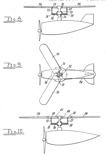
Air vehicle with
rotary wing
US
2881989
1959-04-14

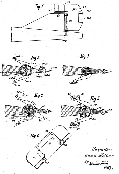
Aircraft
US
2030578
1936-02-11


Flying machine
US
2002287
1935-05-21


Ventilating
device
US
1773453
1930-08-19


Balancing of
aircraft
US
1674546
1928-06-19

Arrangement for
exchanging energy between a current and a body therein
US
1674169
1928-06-19


Rudder
US
1661115
1928-02-28

Method and device
for the steering of ships
US
1661114
1928-02-28


Device for
steering aircraft
US
1574567
1926-02-23


Propeller
US
1556012
1925-10-06


Counterbalance
for rudders
US
1550955
1925-08-25


Steering gear
US
1515024
1924-11-11


Steering device
US
1506821
1924-09-02


Foreign Patents
AIRCRAFT
CA349216
1935-04-02
Hélicoptère à
rotors s'engageant par paires l'un dans l'autre
FR853421
1940-03-19
Anordning ved
Flyvemaskiner med parvis i hinanden indgribende Löfteskruer.
DK65621C
1947-09-08
Anordning ved
Flybemaskiner med parvis i hinanden indgribende Löfteskruer.
DK63034C
1944-12-18
Hubschrauber mit
paarweise ineinander kämmenden Rotoren.
CH212105
1940-10-31
Doppelschrauber
mit Fluegelanschlaegen
DE737528
1943-07-16
Doppelschrauber
mit paarweise ineinanderkaemmenden Steilschrauben
DE733590
1943-04-08
Vorrichtung zum
selbsttaetigen Regeln des Schubes einer Luftschraube...
DE733730
1943-04-10
Avion à ailes
tournantes
FR760549
1934-02-24
Flyvemaskine med
roterende Vinger.
DK51881C
1936-07-13
Flugzeug mit
umlaufenden Tragflügeln.
CH172251
1934-09-30
Dispositif
d'affichage et de publicité
FR690057
1930-09-16
Anzeigevorrichtung.
CH146138
1931-03-31
Anzeige- und
Reklamevorrichtung.
AT124012B
1931-08-10
Steering gear for
vehicles
FR677736
1930-03-13
Lenkeinrichtung
an Fahrzeugen, insbesondere Kraftfahrzeugen...
CH140282
1930-05-31
Dispositif de
ventilation
FR657763
1929-05-27
Anordning ved
afbalancerede Skibsror.
DK39949C
1929-03-25
Gouvernail
équilibré
FR561443
1923-10-22
Procédé et
arrangements pour gouverner des navires
FR27285E
1924-05-31
Steueranordnung
für Wasser- und Luftfahrzeuge.
AT96193B
1924-02-25
Système de
commande pour gouvernails munis de surfaces auxiliaires
mobiles
FR549358
1923-02-08
Improved steering
device for marine and aerial vessels
CH100611
1923-08-01
Rotor à ailes
réglables
FR548285
1923-01-11
Mécanisme
compensateur pour la manoeuvre de surfaces se mouvant dans
un milieu dépourvu de rigidité
FR546815
1922-11-24
Governing of
surfaces moving within alpha nonrigid medium
US1582391
1926-04-27
Improvements
relating to the steering planes of air-craft
CH95937
1922-08-16
Einrichtung zum
Steuern von Schiffen
CH95936
1922-09-01
Hjälperor til
Luftfartöjer
DK32299C
1923-09-24
Styreror til
Skibe
DK31934C
1923-07-09
Indretning til
Styring af Luftfartöjer.
DK30378C
1922-10-02
Schiffssteuerruder.
AT108560B
1928-01-10
Device for
steering aircraft
US1574567
1926-02-23
Method and device
for the steering of ships
US1661114
1928-02-28
Procédé et
arrangements pour gouverner des navires
FR516785
1921-04-26
Durch
Fernverstellung eines mitschwingenden Hilfssteuerruders
betätigbares Hauptsteuerruder.
AT94396B
1923-09-25
VENTILATOR
CA287419
1929-02-26
MARINE STEERING
DEVICE
CA240997
1924-06-24
PROPELLER
CA240996
1924-06-24
DEVICE FOR
STEERING SHIPS
CA234688
1923-10-02
DEVICE FOR
STEERING AIR CRAFTS
CA232284
1923-06-26
wikipedia.org/wiki/Anton_Flettner+%22Anton+Flettner%22&hl=en&ct=clnk&cd=1&gl=us&client=netscape-pp

Anton Flettner
Anton Flettner (November 1, 1885 in Eddersheim (today a district of Hattersheim am Main) – December 29, 1961) was a German aviation engineer and inventor. He made important contributions to airplane and helicopter design.
During World War I, Flettner developed a device allowing to raise or lower a plane's nose for better control, today known as the "trim tab".
Following World War I, Flettner directed an aeronautical and hydrodynamic research institute in Amsterdam.
In the 1920s, he bought a schooner and added two rotating 50-foot cylinders onto it, and thus was the first to build a propulsion system based on the Magnus effect. The ship was named Baden-Baden and crossed the Atlantic in 1926. It could outsail normal schooners under moderate to heavy winds, but was finally destroyed by a storm in 1931. A commercial ship, The Barbara, was also built and sailed to the U.S.
During World War II, he headed the Flettner Aircraft Corporation which specialized in helicopters.
Anton Flettner was also noted for his invention of the famous Flettner rotary ventilator, widely used on buses, vans, boats, campervans and trucks to assist cooling without the use of energy - modern derivatives of his ventilator are still manufactured in Britain by Flettner Ventilator Limited. The helicopter invention was accomplished from his wealth from the ventilator business, whose success also depended on the skill of his wife, Lydia Freudenberg Flettner. Although Anton Flettner built his helicopters for the German military, primarily for navy spotter use, his wife was Jewish. He held a personal relationship with Himmler who in turn had a lower ranked officer and his men escort her family safely to Sweden for the duration of WWII. His partner and confidant was Dr. Kurt Hohenemser, a brilliant and thorough engineer from whom the details necessary for the helicopter's success was derived. Dr. Hohenemser's father was also Jewish, yet the pair remained unharmed during their tenure together throughout the war as they worked to develop the helicopter for military use.
While the final product, the Kolibri FL282 (Kolibri means Hummingbird) was able to be factory assembled, Flettner and Hohenemser insisted that they were the only ones who were capable to assemble the complex intermeshing rotor gearbox assembly. This bottleneck in production kept the FL282 from ever gaining a serious military role.
After 1945, Flettner (along with many other aviation pioneers) moved to America, where he started a new Flettner Aircraft Corporation which developed helicopters for the U.S. military. Flettner's company in the US was not commercially successful, but his work was shared with the Army Air Corp. Many of the Flettner designs are found in Kaman helicopters of later years. Flettner died at 76 years of age in New York City on December 29, 1961.