
rexresearch.com
Fog Collectors
Fog collectors are a simple technology that can produce considerable quantities of condensed water.
But unless the local community participates in the project, it will fail. And even if the locals are involved, some cultures ( e.g., Peruvian peasants ) simply have little "problem-solving capability" -- they cannot make even the simplest maintenance repairs, was learned at El Tofo, Peru.
Years ago I participated in a presentation of Airwells & Fog Collectors with Robert Schemenauer at the Zayed Institute ( Abu Dhabi, UAE ). The sheik ministers politely rejected the idea of fog fences outright for one reason alone : UV light degradation of the plastic mesh. In any case, the plastic mesh degrades within ~ 5 years, is vulnerable to storms, and will not be available when oil prices rise too high, &c.
Alvin Marks and others have developed electrified metal mesh fog fences that do not suffer that problem. But they are large and must be maintained by engineers.
S. Olivier : Fog-Water harvesting along the West Coast of S. Africa : A feasibility study
http://www.scienceinafrica.co.za
Fog-harvesting for water cloud on tap
http://www.nationalgeographic.com
Anne Lummerich : Fog Catchers Harvest Water in Arid Places
A. Gioda, et al. : Fog Collectors In Tropical Areas
Stephen Dale : Collecting fog on El Tofo
http://www.oas.org
Fog Harvesting
http://www.fogharvesting.com/ch33.htm
Fog harvesting in Chile (Chap. 33)
Silsoe College, Cranfield Univ.
S. G. Furey : Fog Harvesting for Community Supply
J. Applied Meteorology ( 1993 )
Robert Schemenauer & Pilar Cereceda : A Proposed Standard Fog Collector for Use in High Elevation Regions
Carolina de la Lastra : Report on the Fog-Collection Project in Chungungo ( 2002 )
http://www.mit.edu/newsoffice/fog-harvesting-0421.html
Out of Thick Air
PATENTS
Fog water collector
US3889532
BACKGROUND OF THE INVENTION
The present invention relate to the collection of fog water and, more particularly, to the collection of fog water by a rotating slotted tubular member which collects the fog water within the slot by impaction and delivers the water to small vials located at both ends of the tubular members.
It is known generally that fog water is comprised of minute droplets of water, ranging from about 2 to 50 microns in radius, condensed on at least partially soluble particulates. However, the fog droplets may scavenge additional particulates and gaseous constituents from the atmosphere which may alter the chemical composition of the droplets. The composition at any given time is an important consideration since the response of the droplets, such as evaporation or growth, to changes in relative humidity is determined in part by the concentration and composition of dissolved salts within the droplets.
Prior techniques for collecting fog water consisted of using a filter media to capture the water, on impaction and dripping from large obstacles such sails, trees and wire screens. Deficiencies of these prior techniques include contamination of samples, excessive time requirements for collection of sufficient samples, and dependence upon a minimum drop size.
The present invention offers the unique advantage of near-complete collection of large quantities of fog droplets of various sizes in a relatively short time interval and is capable of collection rates in excess of one milliliter of fog water per minute, depending on drop size and liquid water content of the fog.
The apparatus of the invention provides a means for collecting sufficient amounts of fog water so that it can be chemically analyzed to determine its composition.
SUMMARY OF THE INVENTION
The present fog water collector takes advantage of the mass of individual fog droplets for collection and uses centrifugal force to concentrate the collected droplets into a sample large enough for chemical analysis. The collector is a hollow slotted tube having small vials at each end to collect the water. The tube is rotated about its center point with fog droplets passing through the slots and impacting on the inside wall of the tube. The centrifugal force, created by rotation of the tube, causes the droplets to move to the ends of the tube where they are accumulated in the vials.
OBJECTS OF THE INVENTION
An object of the invention is to provide a simple and efficient apparatus for collecting large quantities of fog droplets in relatively short time intervals.
Another object of the invention is to collect large quantities for water with apparatus which is of relatively light weight, inexpensive to manufacture and is less cumbersome than prior art techniques.
BRIEF DESCRIPTION OF THE DRAWINGS
Other objects, advantages, and novel features of the present invention will become apparent from the following detailed description of the invention when considered in conjunction with the accompanying drawings, in which:
FIG. 1 is side elevation of the fog water collector of the present invention; and


Turning to FIG. 2, the upper or top half 18 of the collector tube 15, and vial 22 are shown more clearly. The half 18 has a slotted opening 26 which exposes the hollow central portion of the tube. The opening should extend approximately 21 Cm of the total 40 Cm length of each of the tubes. The two slotted openings in both halves of the tube are always formed on the side of the tube facing the direction of rotation so that a slot formed in tube 20 would be on the back side of the apparatus shown in FIG. 1 (on the wall opposite to the slot in the other half of the tube) and would not be visible in that view. The vials may be removably attached to the tube in any convenient manner, such as forming screw thread on both the vial and the tube so that the vial may be easily removed when filled.
The tube 15 may be rotated at approximately 1600 rpm and fog droplets pass through oppositely disposed slots and are collected by impaction on the inside walls of the tube. Fins may be provided on the side of the tube opposite the slotted openings to provide added strength and prevent bending of the tubes, as shown by dotted line 30 in FIG. 2. For example, the fins can be welded to the back side of the tube. Impaction velocities range linearly from 15 to 50 m/sec along the length of the slots provide minimum collection efficiencies ranging from 55 to 75% for droplets of 4 mm radius and larger. Collection rates in excess of 1 ml/min have been achieved with the invention in a dense fog having visibilities of 100-200 m. Increasing the speed of rotation or width of the slot improves the collection efficiency for even smaller drops and increases the volume swept - out per unit time and, thus, provides even greater collection rates.
There has been described a new and simple way of collecting samples of fog water so that it may be chemically analyzed. Obviously, may modifications and variations of the present invention are possible in light of the above teachings. It is therefore to be understood that, within the scope of the appended claims, the invention may be practiced otherwise than as specifically described.
Bipolar fog abatement system
US4475927
The invention pertains to the abatement of warm fog in a designated air space at an airport, such that aircraft can land safely. So far, only the heating method has been used for the dispersal of warm fog; however, the power requirements for this method are very large. It is the object of the present invention to provide a system of fog abatement which requires substantially less power than the heating method.
It appears that an electrical method may provide an approach for such a system. Electric fog dispersal work has been conducted by Ruhnke (1970), Gourdine (1975), and the group at Naval Weapens Center (1972, 1973, 1976); this work is also somewhat related to the electric method of dust suppression, such as described in Gourdine's U.S. Pat. No. 3,757,491, although the possibilities for implementation of electrode configurations are quite different.
The electrified drops which need to be introduced in electric fog dispersal systems may be delivered into the atmosphere by means of air jets. The proposed systems of this type employ charged drops of a single polarity, which need to be blown aloft by the air jets, and which need to get attached to fog drops in order to cause electric precipitation or dilution of the fog. These charged "seeds" must have a small mobility in order that they are not prematurely driven out of the air jets by mutual electric repulsion. On the other hand however, the drops resulting from coalescence of the fog drops and the charged seeds can, at most, acquire the same velocity as the seeds, in the combined electric and gravitational field; this is due to the Wilson velocity limit, noticed first by C. T. R. Wilson (1929), and discussed further by Whipple and Chambers (1944). As a result, the seed mobility restricts the fog clearing speed, which needs to be considerable if new fog is continuously blown in by the wind. The contradictory requirements on the mobility of the charged seeds to be blown aloft by the air jets, i.e., low mobility required to prevent that the seeds are prematurely driven out of the jet, and high mobility required for fast fog clearing, will be called the "mobility dilemma".
One may think that turbulence can provide a resolution of this dilemma. The charged seeds may be brought up to the required height above the ground by turbulent mixing, and a substantial electric field could indeed be set up in this manner, if ground corona could be avoided by some means. However, if the seeds are indeed suspended by turbulence, i.e., the seeds do not precipitate electrically, then the fog drops which have acquired an electric charge by coalescence with charged seeds do not precipitate electrically either; the same turbulence which prevents electric precipitation of the charged seeds prevents electric precipitation of the charged fog drops. It follows that turbulent mixing does not give relief of the mobility dilemma. It is the further object of the present invention to provide a resolution of the mobility dilemma.
Another problem confronting electric fog dispersal schemes which employ electrified jets is due to the corona discharge which occurs at the rough ground surface when the electric field at the ground exceeds a certain value Ec. It turns out that for electric fog dispersal to work, the electric field on the ground must by far exceed the value Ec, and that therefore ground corona would make it impossible to set up the required field. Ruhnke (1970) has proposed to surround the air jet with a polished surface in order to suppress corona discharge. It is the further object of the present invention to provide a practical and inexpensive corona guard over an extended ground area.
Usually, cross wind continuously blows new fog into the air space to be kept clear of fog. This puts very heavy demands on the performance of the fog abatement system. A great relief from such demands may be obtained by substantially diminishing the wind velocity in the spatial region to be cleared, by artificial means. It is yet another further object of the present invention to provide for a substantially cross-wind free condition in the fog treatment region.
By way of summary, the objects of the invention are achieved by introducing electrically charged drops of both polarities, i.e., jet droplets s@+ blown aloft by the jets, and collector drops c@- emitted on the ground at a location downwind of the jet array. The jet droplets s@+ are given sufficiently low mobility such as to stay long enough in the jet to be blown to the required height above the ground, and the collector drops c@- are given high enough mobility for fast collection of fog drops in an upward motion in the collective electric field set up by the s@+. Ground corona is prevented by means of a shallow basin filled with water and oil; the water-oil interface provides for the smooth conducting surface required, and the oil layer prevents evaporation of the water. The desired substantial stilling of the fog treatment region is achieved by means of a gapped jet, consisting of a linear array of air jets with spacing and momentum flux chosen in such a manner that the air flux entrained at the lee side of the jet array is substantially equal to the crosswind flux which penetrates the jet array.
The invention will be fully understood from the following detailed description and accompanying drawings, in which:
FIG. 1 shows schematically the fog abatement configuration;


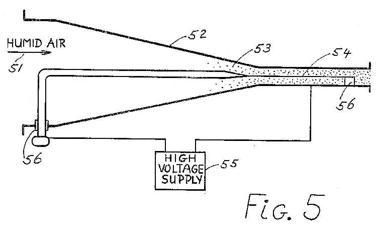
FIG. 2 shows a cross section of the aerodynamic and electric configuration in a direction perpendicular to the runway. Shown are the runway 11, the shallow basin 12, one of the air jet nozzles 13, the crosswind component 14, one of the air jets 15, the virtual electrode 16, a cluster of drop dispensers 17, and jet droplets s@+ blown aloft by the air jet 15. The figure shows how the air jet is bent over by the crosswind and by the transverse electric loading, and how the jet spreads due to turbulent diffusion and entrainment, and also due to the electric body force which results from the mutual repulsion of the s@+. The collector drops c@- move upward toward the virtual electrode 16, in the field of the s@+, the c@-, and the conducting ground, and the c@- are transported as well with the small air velocity remaining at their location. This air velocity is small compared to the wind because of arrangements to be discussed presently. The turbulent jets entrain surrounding air from all sides. If the jet were two-dimensional, i.e., without gaps, the entrainment on the lee side would set up a circulatory flow underneath the jet, bent over by the wind. Analysis has shown this circulatory flow to be detrimental to fog abatement. The circulatory flow can be quenched by means of gaps in the jet, chosen in such a manner that the lee side entrainment flux is just provided by the wind flux which penetrates through the jet gaps. Shown is a streamline 38 of crosswind penetrating through the gap between adjacent jets and curving upward and inward towards the jet in the process of entrainment. This streamline is also shown in FIG. 3 as 38. The arrangement with equal fluxes of wind penetration and lee side entrainment discussed above is called "a gapped jet with balanced perforation ratio". When the condition of equality of fluxes is satisfied, the lower jet boundary 29 of FIG. 2 acts as a virtual canopy, shielding the "cavity" 30 underneath the virtual canopy substantially from the wind, and even quenching the circulatory flow which develops behind a partial material windshield, as in the case of a convertible automobile with the top down. Hence, the gapped jet with balanced perforation ratio causes the air in the fog treatment space to be substantially still. This results in rather steep initial trajectories 31 of the collector drops c@- emitted by the drop dispensers 17. There will be a small residual velocity of air flowing through the spatial region 32 which is being traversed by the fast moving collectors c@-. At the upstream end of region 32 the air is laden with fog drops. Conditions can be arranged such that the probability for capture of a fog drop by one of the collectors c@-, as the fog drop moves through region 32, is close to unity. Then nearly all the fog drops moving through region 32 coalesce with one or more c@-, i.e., these fog drops acquire a charge, and they are moved upward by the electric field. Analysis shows that parameters can be chosen such that this upward motion and removal of the charged fog drops occurs fast enough to leave a substantial region 33 with large enough visibility to make visual aircraft landings possible. Outside fog diffuses through the jet by turbulent diffusion, and therefore the surface of marginal visibility curves downward towards the ground, past the runway, as shown. The electric field E set up by the s@+, the c@-, and by their images in the ground exerts a body force on the jet which adds to the jet curvature due to the crosswind. In the region where the s@+ and the c@- meet there is neutralization of the charges of opposite polarity, so that downstream of this region the jet is substantially neutral, and there is no electric loading.
FIG. 4 shows schematically the electric current path due to the motion of the fog droplets s@+ and the collector drops c@-. The s@+ are emitted by the jet at 43, and the c@- are emitted by the drop dispenser at 44. The electric current I flows as shown; at the cusp 45 the neutralization of s@+ and c@- takes place. In the description given above, the jet drops have a positive electric charge, and the collector drops have a negative charge. The opposite choice of polarities is possible also, and the choice in practice will depend on convenience and the differences between postitive and negative coronas.
In addition to the crosswind effects discussed above, one must account for the component of the wind parallel to the runway. Such a wind component will increase the turbulent diffusion of fresh fog through the top of the canopy, and it will slant streamlines in the direction of the runway. Neither effect is expected to affect the feasibility of the present fog abatement system.
The nozzles 13 which emit air jets 15 laden with electically charged drops s@+ can be constructed in a manner known to those skilled in the art, as follows. Referring to FIG. 5, humid compressed air 51 laden with an appropriate concentration of aerosol of appropriate size and constitution is expanded through a nozzle 52 causes a condensation of water vapor on the aerosol, resulting in the formation of doplets 53 in the flowing air. The droplets are electrically charged by means of a corona discharge from a corona wire 54 connected to a high-voltage supply 55; the corona wire assembly is insulated from the nozzle by insulators 56. A spray gun of a similar type, developed at Gourdine Systems, Inc. has been described by Chiang et al (1973).
The drop dispensers which are to emit the charged collector drops c@- can be of similar construction as the nozzle described above, albeit with a much reduced air flow, but it is also possible to build a drop dispenser by producing the collector drops with a high-pressure spray and by charging the drops inductively, as described, for instance, by Ruhnke (1970), and by Carroz and Keller (1976).
The gapped jet with balanced perforation ratio has independent merit as a device to reduce air velocity in other methods of fog abatement, such as the heating method.
A shallow basin containing water and oil may be used wherever a corona guard on a horizontal surface is required. There is a threshold value for the electric field above which a Rayleigh instability of the water-oil surface occurs, which causes highly charged water drops to break away from the interface, move upward through the oil, and emerge into the air. The threshold field may be calculated from theory. A preliminary test using a 1/4" layer of SAE 30 motor oil on water showed on instabilities for electric fields up to 6.times.10@5 V/m, about the largest field under consideration for the present method of electric fog abatement.
The gapped jet with balanced perforation ratio may in first approximation be designed from the following consideration. The entrainment volume flux on the lee side of a two-dimensional turbulent air jet, per unit of time and span, is
F(s)=0.31.sqroot.Ks, (1)
where K is the kinematic jet momentum flux per unit time and span, and s is the flow distance along the jet centerline. Let the gaps in the jet array be such that a wind flux .omega.hU0 penetrates the jet; .omega. is a coefficient to be determined, h is the height to which the jet rises, and U0 is the wind velocity, here assumed independent of height. In order that the penetrating wind flux precisely provides for the lee entrainment, one must have
.omega.hU0 =0.31.sqroot.Ks; (2)
in (2), s is the arc length along the jet to a point where entrainment ceases. For order-of-magnitude purposes, this s is taken such that the half width of the jet at half velocity equals the jet height h,
h=0.115s, (3)
where use has been made of the Tollmien theory of turbulent plane jets (see Schlichting (1968)). For the gapped jet with perforation ratio .omega., the inviscid model gives, from momentum conservation in the direction of the crosswind,
K=h(1-.omega.@2)U0@2. (4)
Consistency of (2), (3), and (4) requires
.omega.=0.7; (5)
as a consequence, (4) gives
K=0.5hU0@2. (6)
(6) gives an approximate value for the kinematic momentum flux per unit of time and span which is needed in order that the gapped jet rises to a height h above the ground, in a crosswind with velocity U0. (5) gives an approximate value for the perforation ratio of the gapped jet, needed for balancing of the lee entrainment flux and the wind penetration flux.
The condition of low mobility for the electrically charged droplets blown aloft by the air jets may be stipulated as follows. Let E0 be the maximum electric field due to the jet droplets s@+ blown aloft by the jets. For the electric current I carried by the jet array per unit span (span is in the direction of the array) one has approximately
I=.epsilon.E0 U0, (7)
where .epsilon. is the dielectric constant of air. Let .theta. be the slope of the half-velocity line in the jet, with respect to the center line, and let .DELTA..theta. be the ratio of the transverse electric velocity of the s@+ at the outer edge of the jet, and the crosswise-average jet velocity. From the Tollmien theory, (6), (7), and electrical considerations one finds, for small .DELTA..theta., ##EQU1## where ks is the electric mobility of the s@+. In order that the s@+ are not prematurely driven out of the jets one must have ##EQU2## small compared with unity. For ##EQU3## one has from (8) ##EQU4## as the condition for "low mobilty".
The collector drops c@- emitted by the drop dispensers 27 are subject to the electric field due to the s@+, the c@-, and their ground images. If the s@+ and c@- currents are equal, the electric field at the most crosswind-downstream c@- position is relatively small, because of the screening by the c@- in more upstream locations. A large electric field, even at the most downstream c@- position, is desired in order that the c@- have steep trajectories. Therefore, it is desirable to apply a booster field, and this can be done simply by making the electric current carried by the s@+ substantially larger than the current carried by the c@-. Then, at the cusp 45 there will not be complete neutralization, and a substantial space charge will be carried off from the cusp region by the wind and the jet. As a rough guide, the s@+ current can be chosen as about twice the c@- current.
If an electric field in excess of Ec would exist on the ground at the location of the collector drop dispenser, the water-and-oil basin should be extended to cover this location.
The condition of high mobility of the electrically charged collector drops may be stipulated as follows. The c@- mobility should be large enough that the c@- trajectories are sufficiently steep to provide an adequate airspace cleared of fog. Let Uc and Ecol be respectively the horizontal air velocity and the electric field, averaged across the c@- trajectories, at a height of 1/2h above the ground. Uc is much smaller than the wind velocity U0, because of the shielding effect of the gapped jet with balanced perforation ratio. The average slope of the c@- trajectories will be judged adequate in this context if ##EQU5## where kc is the electric mobility of the c@-. (10) is taken as the condition for "high mobility".
Although for efficiency it is best to have all s@+ of one polarity, it is possible to have a system in which the jet droplets have electric charges of both polarities, and similarly, to have collector drops with electric charges of both polarities, as long as the predominant polarity of the jet droplets is different from the predominant polarity of the collector drops. In the above, "predominant polarity" is defined as the sign of the average electric charge.
The gapped jet is described above as a linear array of jets emitted from nozzles, which may be taken as axisymmetric. Alternately, the nozzles may have the shape of rectangular slots. The gapped jet may then seen as a jet emited from a long slot, which is periodically blocked.
In the above, an airport is taken to be the site at which the fog abatement system is applied. The system may be applied as well to an aircraft carrier, or a roadway, an oil drilling platform, a sea going vessel or platform, or any other structure or site where the visibility must be maintained above a certain level.
This invention is not to be limited by the embodiments shown in the drawings and described in the description, which are given by way of example and not of limitation, but only in accordance with the scope of the appended claims.
Device for catching mist or fog microdrops or drops of rain, and their combination for subsequent storage
PT102351

Fog collector and its application method
CN101000289

Fog-condensation water collector
CN201326191
DESCRIPTION [ uncorrected machine translation ]
First, the technology
The invention belongs to the field of ecological engineering technology, simple method involving a manufacturing fog collector.
Second, the background art
Fog, as an important level of precipitation in the ecosystem, especially in coastal ecosystems and mountain ecosystems, water has a unique position in the sub-input, affect the ecosystem of the water cycle, nutrient input, the relationship between plant species and species diversity.
In addition, in some severe arid regions, such as northwest China, western South America and other places, due to scarce rainfall, fog is an important water resources can be used to ease or even eliminate the local water shortages.
However, the long-term human fog remains in the superficial level, so that the fog is called "recessive precipitation (Occult precipitation).
In the late 20th century, foreign research on fog starting to focus on, and since 1998 held two International fog Symposium, from different angles, carried out extensive research on fog; causes such as different areas of fog, mist physical Chemical properties of hydrological processes involving fog, fog impact on biodiversity and ecosystem structure and function, how humans With the fog of this important water resources.
Currently, our academia fog has not yet commenced, in the fog of the ecological significance of water meaning Was virtually nonexistent.
Those who wish to carry out research in this regard, we must solve the problem of fog water samples collected in the field conditions.
Very few fog-related research, the sampling method is only exposed to the weather the containers to undertake fog, did not take into account the wilderness environment
Rain sampling interference, cannot meet the requirements to avoid water evaporation experiments, while the collection efficiency and lower; while foreign Existing the fog collection instruments and expensive.
Third, the invention content
The object of the present invention is:
The use of common materials, design a fog water collection device suitable for fog water collected under field conditions.
It has a high fog Water collection efficiency, and can effectively remove the wilderness environment, the vertical precipitation and evaporation fog water collection, carried out for the future
The fog of scientific research activities to provide a cheap and efficient means of experiments.
The program of the present invention is:
Field under the conditions of the present invention is used to collect fog.
The fog collector lid blocked by the rain stopped, the two layers of fog water absorption of the network, the fog brings together dish, connected shanks and feet.
Rain gear cover 0.3 cm thick iron bar system was the canopy like the canopy bottom diameter of 130 cm, 25 cm high.
Canopy plus paint to prevent rust under field environment.
This section is used to block stopped the rain, thus weakening the impact of rain fog water collection,
Rainwater stopper Elam cover inner surface of a fishhook-shaped hook and beyond twice, three hooks of each circle are equally spaced, the inner and outer circle hook distance
Cover centers of 6 cm and 9 cm, respectively for hanging fog absorption network of outer and inner layers, two layers of interconnection 3 cm apart.
Stopper stopped at the center of the lid inner surface is welded for connecting stopper Elam cover the connection head and connection shank, by a high 5 cm, diameter 3 cm circular Threaded base, the base 2 cm thick, smooth part and base 2 cm long, 6 cm long, 1.5 cm thick, smooth and free of Threaded fittings welded together, as shown in Figure 1, Figure 2.
Absorb fog water network is two layers of nylon mesh system for absorption fog.
Mesh size of 0.5 mm × 0.5 mm -1 mM M × 1 mm.
Across the outer online distance of 60 cm, the intranet 80 cm.
Ends were sewn around each layer online
Two 0.5 cm thick stainless steel ring, wherein the outer layer mesh with rims diameter of 18 cm, inner rims network diameter
Upper end of the steel ring for hanging the net in rain gear stopped the lid on the inner surface of the hook, the lower end of the rim for the network the lower end fixed to 12 cm;
Not the breeze avoid the network the breeze thrown online sticky fog, and brings together online fog.
In order to improve Fog absorption efficiency, cut out a few large opening in the outer network, and to facilitate that the fog can be floated into the inner layer and are absorbed within the network Two layers
Network system, hanging in the rain gear bar the lid on the inner surface of the hook.
When the fog will be exposed to a two-tier network interception, and brings together the flow Pooled into the fog dish, as shown in Figure 3.
Fog pooled dish for pooled absorbed into the fog, conical stainless steel container, dish wall thickness of 0.3 cm, the dish mouth diameter of 20 cM and a height of 30 cm.
Dish port has a width of 0.8 cm, a thickness of 0.3 cm of the projecting rim, on which an equal pitch welded three screw port for connecting Three legs connected fog collector, the pore size of the screw port of 0.3 cm.
Near the center of the bottom of the dish, with the rainwater retaining stopped at the center of the inner surface of cover
For connecting gear cover and connector connection handle bar, in addition to base under smooth part 7 cm long, the other parts of the specifications and rain Block Elam cover connector; connector through the three thickness of 0.2 cm the wedge iron pan wall welding.
The bottom of the dishes have a diameter of 0.8 cm
Opening rough rubber tubing on the sets, fog thus the flow of the sample collection bottle; collection bottle in advance by adding a small amount of mineral oil in order to maximize Reduce fog water evaporation, as shown in Figure 4.
Fog pooled the dish with rain gear Elam cover through a connection handle connected.
Connection handle is 60 cm long, 2 cm thick irons.
Irons in the At each end of the inner diameter of 1.5 cm, 6 cm long hollow portion of the hollow part of the non-threaded; rod end and 0.2 cm thick, 0.5 cm wide and sudden
The edge; sets of subsequently fixed with 0.2 cm thick iron sets one side of the iron jacket is threaded 5 cm long, 3 cm inner diameter, which rely on
Near one end of the rod end is full open, the other end opening to an inner diameter of 2.2 cm, and this is designed to ensure that it can not be detached from the rod.
Installation, Connecting the handle end of the hollow section sets pole in the socket, rotating fixed iron sets it with circular base riveting, can be connected to the handle rain stop
The dish of Elam cover and fog brings together close connection, as shown in Figure 5.
The feet are used to support the entire device.
Three feet, each length of 150 cm and 1 cm thick, painted.
To feet end there and Thread, and fog pooled engaging screw fog pooled dish rim dish at a 45 ° angle.
Branch at the foot end of the tip, Lee on uneven ground
The segment fixing means can be inserted into the soil, as shown in Figure 1.
The size of the various components and specifications, adjust slightly due to different locations of specific experiments.
The effect of the present invention in that:
The fog collector constructed according to the method open fog in the wild windward zone suitable for collecting fog.
Not only does it have a more
High fog water collection efficiency, but also effectively avoid the vertical precipitation and evaporation fog water samples collected at the same time low cost
For the future fog Research provides the necessary experimental equipment.
IV BRIEF DESCRIPTION OF THE DRAWINGS
Figure 1 fog sectional view of the collector.
a. Rainwater stopper Elam cap, b.
The rain gear Elam to cover the inner surface of the hook, c.
Inner layer of stainless steel circle,
d.Outer layer of nylon mesh, e.
Inner layer of nylon mesh, f. Fixing iron sets, g. Connection handle end of the projecting edge, h. Connection head fittings, i. Connecting stem, j. Fog pooled screw port of the outer edge of the dish port, k. The outer stainless steel ring, l. Connection head screw base, m. Fog pooled Dish, n. The welding wedge tin, o. Feet, p. The smooth portion of the connector, q. Rubber tubing; measurement unit: cm.
Figure 2 rainwater stopper blocking the cover inner surface.
a. Hooks, b. The location of the outer layer of stainless steel ring, c. Location of the inner stainless steel ring
d.Connectors; Measurement Unit: cm.
The Figure 3 fog absorption Network.
a.The inner layer of stainless steel ring, b. The outer stainless steel ring, c. The inner layer of nylon mesh, d. Outer layer of nylon mesh;
Measurement Unit: cm.
Figure 4 the fog brings together dish.
a. Fog pooled dish projecting edge,
b. Fog pooled screw port of the outer edge of the dish port
c. Connector Fittings
d. Connection head screw base
e. Smooth part of the connector base
f. Welding wedge tin,
g. Fog pooled
The dish lower end of the opening; measurement unit: cm.
Figure 5 is connected to the handle, rain gear of Elam cover and fog brings together dish.
a.Connector threaded base, b. Fixing iron sleeve, c. Rain Water stopper Elam cover, d. Even the head of the fittings, e. Connecting stem, f. Connection handle end of the projecting edge, g. Header smooth portion, h. The fog brings together dish; Measurement Unit: cm.
V. PREFERRED EMBODIMENTS
The device has been put into use, the Wolong Nature Reserve in Sichuan the Balang alpine meadow at 3720 meters above sea level the three samples ground And the closing fog effects; August 2005, a device placed in the alpine meadow open windward zone, each foggy evening.
Collected fog; experimental period of 12 days of fog, fog water samples collected from 12 sample volume between 20-70 ml.
Its with Body using the following steps:
The first step, according to the foregoing description of the instrument to be assembled.
Select the mesh size of 0.5 mm × 0.5 mm, 1 mm × 1Mm nylon mesh.
The second step, field trips, choose a better location setting of instruments.
To windward, the open area is better.
Third step, place the sample collection bottle and, if necessary, into a small amount of mineral oil in order to reduce the evaporation of water in the bottle.
Removed fitted with the fourth step, the fog stopped fog samples collected bottles, and replace it with a new bottle, continue to be a subsequent acquisition.
Collecting device of fog and automatic-sorting aerosol and application method thereof
CN101769831

DESCRIPTION
Technical Field
The present invention relates to the field of atmospheric science and environmental science, especially involving technology for the collection of meteorological observation and the ground wet deposition and aerosol integration classified information collected.
Background Art
Fog, generally there are three definitions: 1) all the atmosphere due to suspended condensation, the visibility is less than 1 km, meteorologists said this weather phenomenon for the fog.
2) Fog is a cloud close to the ground.
3) Fog is constituted by the micro-droplets suspended in the atmosphere of the aerosol. Made fog (cloud), a necessary condition is that there must aerosol is present and to be activated.
Fog and aerosols joint classification study atmospheric and environmental sciences research.
Fog generated aerosol activation into cloud condensation nuclei are inseparable, and aerosol physical, chemical resistance and wet deposition of fog (cloud) have an important impact.
At present, China's meteorological community has not yet commenced routine observation of fog and aerosols Classification of academia integrated fog and aerosols have not been reported.
Those who wish to carry out research in this regard, it must resolve the external field condition, aerosols Category, haze (cloud) of water and aerosol collection problem.
The existing domestic very few involving fog and aerosol research, only a single fog water collection, or a single aerosol collection.
Without integration, automatic classification sampling research.
How to set up an integrated automatic classification and cheap fog (cloud) water, aerosol collection device, which is a prerequisite for the country to carry out research in this regard and conventional meteorological observations.
SUMMARY OF THE INVENTION
An object of the present invention is to provide a high collection efficiency, the the vertical precipitation and evaporation haze (cloud) of water collecting in the observation field environment can be effectively avoided, and the low cost of the fog and automatic classification of aerosols collecting apparatus and application methods.
A fog and collecting apparatus of the automatic classification of aerosols, including fog collecting portion, aerosol collecting portion, the data processing section,
Fog water collecting portion includes an intake port, the intake passage, fog absorption network, fog pooled dish, fog measurement, sensors, fans, are respectively connected at both ends of the intake port of the intake passage, fog absorption net, fog the lower end of the water absorption of the lower end of the network connection fog pooled dish, fog pooled dish connection fog water meter, the fog water meter is provided on the sensor, the fog absorption network set fan away from the side of the intake passage;
Aerosol collecting portion including juxtaposed first aerosol sampler, the second aerosol sampler, the first aerosol sampler the second aerosol sampler of fog in the fan away from the absorption side of the net, the first aerosol sampling of gas on the road to connect the first gas-way controller, the second aerosol samplers gas on the road to connect the second gas line controller;
The data processing section including a display, a micro-data processor, data memory, RS-232, and a telephone modem, the micro-data processor the first data output terminal connected to the data input terminal of the display, the data output terminals of the sensor and micro data processor connected to the first data input terminal, a second data output terminal of the micro-data processor with the first gas passage controller, the data input terminal of the second gas passage controller connection, a data memory data output terminal of the micro-data processor second data input terminal is connected, the data input terminal of the third data output terminal of the micro-data processor and data memory, the micro-data processor the output end of the fourth data and the RS-232 data input terminal is connected, the micro-data processor a fifth data output terminal is connected to the data input terminal of the telephone modem.
The present invention, the upper end of the intake port is set rainwater cover stopper Elam.
The first aerosol sampler of the present invention, the gas path of the second aerosol sampler is connected to a vacuum pump.
Based on the application method of the fog and automatic classification aerosol collecting apparatus, comprising the steps of:
The first step: in the clouds before the events of the first aerosol sampler open traffic sampling;
Step two: when the start of the event cloud, mixed clouds and aerosol air first enters the fog water collection part, by the inlet into the intake channel, online touch the fog cloud water absorbed in the fog and collect pooled in the fog brings together dish pooling fog of water droplets formed on the dish dropwise fog measurement, fog measured gravity balancing means, when the judgment droplets be turned under gravity, starts counting, and data is transmitted through the sensor to the microcomputer data processing device;
The third step: micro data processor receives the data, control the second gas line controller action to open the second aerosol sampler gas line, gas collected after the second step of the fog into the aerosol collection part start collected aerosol; micro data processor to control the first gas path controller to turn off the gas path of the first aerosol sampler;
Step 4: When the clouds after the incident, fog meter stops counting, micro-data processor receives the sensor signal in the fog on the meter, through the control of the second gas line controller close second aerosol sampler gas line while controlling the first gas-way controller to open the first aerosol sampling gas path.
The present invention employs the above technical solution, compared with the prior art has the following advantages:
1, the collecting portion of the present invention, the fog, the collected fog collecting part in the aerosol, the collected aerosol, automatic classification of the total atmospheric particles and difficult to be activated and not wet deposition clear aerosol.
Can also be based on the research needs, and adjust the program to collect different classification of the aerosol.
2, the present invention is integrated fog and aerosol collector suitable for outfield fog zone to collect fog (cloud) water and aerosols.
Collection of fog (cloud), it is not only higher fog water collection efficiency, but also effectively avoid the vertical precipitation and evaporation fog water samples collected at the same time a low cost.
In aerosols collected, it is based on scientific research need to select different types of samplers, adjusting the sampling by pneumatics end control, so that there is greater flexibility to research and select sampling.
Data processing part, to connect fog meter and the aerosol gas line controller may need to collect different types of aerosol research, provide valuable observations understand ascertain aerosol clouds and wet deposition.
BRIEF DESCRIPTION OF THE INVENTION
Figure 1 is a schematic view of a structure of the present invention.
Figure 2 is a plan view of the Figure 1.
Figure 3 is a schematic diagram of the structure of the data processing portion of the present invention.
DESCRIPTION OF THE PREFERRED EMBODIMENTS
Below with reference to the technical solution of the present invention will be described in detail:
As shown in Figure 1, Figure 2, a fog and automatic classification aerosol collection device, characterized in that it comprises fog water collecting portion, aerosol collecting portion, the data processing section,
Fog water collecting portion comprises an intake port 2, the intake passage 3, fog absorbent network 4 pooled dish 5, fog and fog metering device 6, sensor 7, the blower 8, the ends of the intake passage 3 are respectively connected to the intake port 2, fog absorption Network 4 fog absorption Network 4 is connected to the lower end of the fog brings together the dish 5 fog pooled pan 5 is connected to the lower end of the the fog water meter 6, fog metering sensor 6 7 fog water absorption Network 4 away from the side of the intake passage 3 fan 8 is provided;
Aerosol collecting portion includes a juxtaposed first aerosol sampler 9, the second aerosol sampler 10, a first aerosol sampler 9, the second aerosol sampler 10 are located in fan 8 away fog absorption Network 4 the gas path of the side of the first aerosol sampler 9 connecting the first gas path controller 11, the air line connecting the second gas path of the second aerosol sampler 10, the controller 12;
The data processing section includes displays, micro-data processor, data memory, RS-232, and a telephone modem, the micro-data processor the first data output terminal is connected to the data input terminal of the display, the data output terminal of the sensor 7 and the micro-data processor connected to the first data input terminal, a second data output terminal of the micro-data processor with the first gas passage controller 11 and the data input terminal of the second gas path of the controller 12 is connected, the data output terminals of the data memory and micro data second data input terminal of the processor is connected, the micro-data processor the third data output terminal of the data memory the data input terminal is connected, the micro-data processor the output end of the fourth data and the RS-232 data input terminal is connected, the microcomputer fifth data output terminal of the data processor and the data input terminal of the telephone modem connection.
Shown in Figure 1, the present invention, the upper end of the intake port 2 rainwater stopper Elam cover 1.
The first aerosol sampler of the present invention 9, the gas path of the second aerosol sampler 10 is connected to a vacuum pump.
The vacuum pump is always active in the fog and aerosols acquisition process in.
Based on the application method of the fog and automatic classification aerosol collecting apparatus, comprising the steps of:
Step 1: in the clouds before the events of the first aerosol sampler open flow sampling;
Step 2: clouds event starts mixed cloud and aerosol air first enters the fog water collecting portion, by the air intake port 2 into the intake passage 3, the fog cloud water absorbed in the fog network 4 touch and collected together in the fog water collection dish 5, fog pooled water droplets trickle fog metering device 6 is formed on the dish 5, the fog measuring 6 gravity balancing means, when the judgment droplets turned under gravity, to start counting, and The data by the sensor 7 is transmitted to the micro-data processor;
The third step: micro data processor receives the data, control the second gas line controller 12 action, gas line to open the second aerosol sampler 10, after the second step of the fog acquisition of gas into the aerosol collection the part began collecting aerosols; micro data processor to control the gas path of the first gas path controller 11 to close the first aerosol sampler 9;
Step Four: When the clouds after the incident, the fog meter stops counting micro data processor receives the signal of the sensor to the the fog water meter 6 7 close second aerosol sampling, by controlling the second gas line controller 12 10 gas path and control first gas path controller is open the first aerosol sampler 9 gas line 11.
Automatic collector
CN102175488
The invention discloses an automatic collector, comprising a box body, a rain sensor, an electric control box, a collector, as well as a gathering device, an axial-flow fan, an absorption screen, a fog-receiving groove and a conduit, wherein the gathering device is fixed in the box body; the axial-flow fan is arranged on a side face of the box body, and electrically connected with the electric control box; the absorption screen is arranged on another side face of the box body; the another side face is opposite to the side place where the axial-flow fan is arranged; the fog-receiving groove is arranged just below the absorption screen, and is provided with an opening at the two ends respectively; one end of the fog-receiving groove is fixed on the side wall of the box body; the other end of the fog-receiving groove is fixed through a bracket; and one end of the conduit is connected with the openings of the fog-receiving groove, and the other end of the conduit is arranged in the gathering device. By using this scheme, the work of the axial-flow fan is controlled by the electric control box, fog water collides with the absorption screen and is absorbed by the same under the suction force of the axial-flow fan, water beads are formed by the fog water under gravity action, flow into the fog-receiving groove which is located just below the absorption screen along the absorption screen, and then flow into the gathering device through the conduit, so that the collection of fog water is realized, the workload for an operator is reduced, and the working efficiency is improved.
Automatic acquisition device
CN201993251
The utility model discloses an automatic acquisition device which comprises a box body, a rain sensor, an electrical control box, an acquisition device, a collector, an axial flow fan, an adsorption silk screen, a fog receiving groove and a duct, wherein the collector is fixed in the box body; the axial flow fan is mounted on one side surface of the box body and electrically connected with the electrical control box; the adsorption silk screen is arranged on one side surface of the box body, which is opposite to the side surface on which the axial flow fan is mounted; the fog receiving groove is arranged right below the adsorption silk screen; openings are formed at the two ends of the fog receiving groove; one end of the fog receiving groove is fixed on the side wall of the box body, and the other end of the fog receiving groove is fixed through a support frame; and one end of the duct is connected with the corresponding opening of the fog receiving groove, and the other end of the duct is placed in the collector. By adopting the scheme, the electrical control box controls the axial flow fan to work; under the action of the suction force of the axial flow fan, and fog water collides with the adsorption silk screen and is adsorbed by the adsorption silk screen; and under the action of the gravity, the fog water forms water droplets and flows into the fog receiving groove right below the adsorption silk screen along the adsorption silk screen, and then flows into the collector through the duct, so that the acquisition of the fog water is achieved, the workload of the operating personnel is further reduced, and the work efficiency is improved.
Rainwater, ice, snow, thick fog, humidity and temperature collector
CN202057816
The utility model discloses a rainwater, ice, snow, thick fog, humidity and temperature collector which is composed of a rain, snow and ice sensor and a thick fog sensor, wherein the rain, snow and ice sensor is composed of gilded rain, snow and ice coiled copper foils and a temperature sensor integrated circuit fixed on the front surface of a rain, snow and ice circuit board, and the thick fog sensor is composed of gilded thick fog coiled copper foils and a temperature sensor integrated circuit fixed on the front surface of a thick fog circuit board. A signal collecting box is installed on a central isolation belt of a highway or steel pipes at two sides of the highway, the thick fog sensor is installed on a top board in the signal collecting box, and the rain, snow and ice sensor is installed on a top board outside the signal collecting box. The rainwater, ice, snow, thick fog, humidity and temperature collector has the advantages that the collected meteorological information is accurate, all kinds of meteorological information is collected, and the collector is simple in structure.
US Patent # 4,206,396
Charged Aerosol Generator with Uni-Electrode Source
Abstract --- This invention relates to novel charged aerosol sources for diverse applications in Heat/Electric Power Generation, weather modification, airport fog clearance, dispersed chemical reactions, and other uses; and in particular, to a Wind/Electric Power Generator deriving electric power from wind power directly without moving mechanical parts through the medium of charged water droplets introduced into the airstream from a charging electrode, the charged droplets eventually discharging to ground, the electrical load being connected between the charging electrode and ground to complete the circuit...
This invention relates to novel charged aerosol sources for diverse applications in heat/electric power generation, weather modification, airport fog clearance, dispersed chemical reactions, and other uses; and, in particular to a Charged Aerosol Wind/Electric Power Generator.
The devices according to this invention have the advantages of increased efficiency, simplified construction, and decreased cost.
Charged aerosol electric power generators have been described in my previous United States Patents@1.
It is an object of this invention to provide droplet emitters to produce about 1 .mu.A for a power input of 4 mW or less; that is, with a ratio of current output/energy input >250 .mu.A/watt. Such emitters are particularly useful for power transduction.
It is a further object of this invention to provide a simplified electrical circuit for a charged aerosol power converter.
A BRIEF DESCRIPTION OF THE FIGURES
In the Figures:
FIG. 1 shows a perspective view of a large scale wind/electric power EFD generator array.
FIG. 2 shows a front view of FIG. 1.

FIG. 4 shows a Condensation Method of forming a charged aerosol in a charged aerosol generator.
FIG. 5 shows an Electrojet Method of forming a charged aerosol in a charged aerosol generator.
FIG. 6 shows a diagrammatic perspective view cut away on a vertical plane of a wind/electric power generator showing details of the emitter, collector, and exciter electrodes.

FIG. 8 shows electric power density, wind kinetic power density, and conversion efficency versus wind velocity.

FIG. 10 shows a generalized diagram of a single electrode charged aerosol generator with electrical and/or mechanical input power to actuate the emitter source. The electric potential field due to space charge is also shown.
FIG. 11 is the same as FIG. 10, showing a portion of the generated electrical power used to actuate the emitter source.

FIG. 12 shows a single electrode charged aerosol generator connected to produce a stepdown AC output.
FIG. 13 shows a detail of a portion of a liquid jet charged by contact with the metal.
FIG. 14 shows the generalized dimensions of a slit orifice.
FIG. 15 shows a charged aerosol microjet emitter comprising an array of slit orifices.
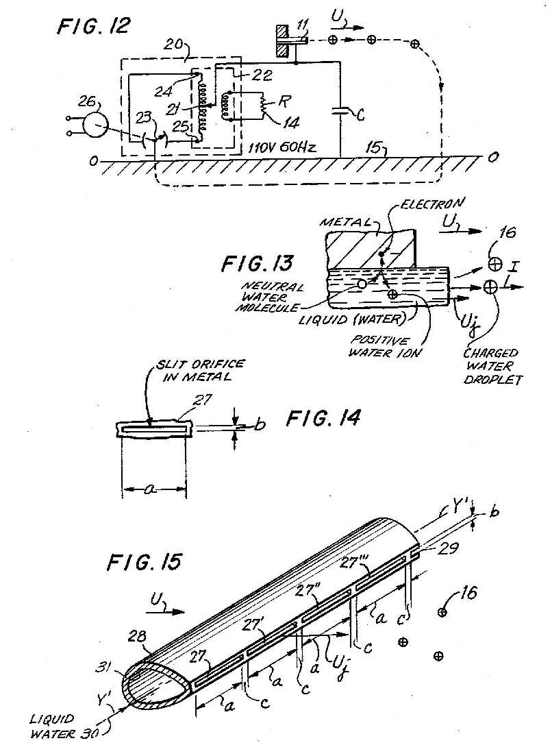
FIG. 17 shows a microjet emitter using steam/metal charging with a miniature flash boiler as an internal steam source.

FIG. 19 shows a wind/electric power generator with a microjet, condensation charging, an internal point ion emitter, and a miniature flash boiler as an internal steam source.
FIG. 20 shows an assembled microelectrojet connected with a water source and compressed air source.

FIG. 22 shows a magnified cross sectional view of a microelectrojet source of charged water droplets.

FIG. 24 shows a front plan view of the free air electrojet of FIG. 23.
FIG. 25 shows a cross section of a microjet and exciter electrode for producing charged water droplets by induction of a water jet.

FIG. 27 shows a charged aerosol heat/electric power generator utilizing a single electrode source, with the charged aerosol discharging into the interior of the duct and showing the voltage created by the space charge.

BACKGROUND OF THE INVENTION
Wind is an inexhaustable source of pollution-free power. Wind power has been used in a small way for thousands of years to propel sailing ships or to operate windmills, which are mechanical devices. The present invention is unique in that for the first time a means has been provided for the direct conversion of wind power to electric power without moving parts except charged water droplets.
According to this invention, a charged aerosol electrogasdynamic generator at atmospheric pressure is powered directly by the wind. It comprises a large area electrode screen which emits charged water droplets into the windstream as a wind/electric power transducer.
In the wind/electric power generator shown in FIGS. 1 and 2, a large area electrode screen of special construction is mounted in a vertical plane to intercept the wind. Wind/electric power generators according to this invention will be installed at suitable geographical locations (updrafts at mountain ranges, along seashore fronts, etc.) where there is a steady strong flow of air in one direction at most times at 5 to 20 m/sec velocity.
Assuming a wind velocity of 10 m/sec, the wind power converted to electric power@2,3 is 0.45 kW/m@2. For example, such a screen 100 meters high and 1,000 meters long; or a screen area of 10@5 m@2 /km will generate an electric power output of 45 megawatts/km at about 100,000 volts DC. If 10 such screens are spaced 1 km in depth, and extended in length of 100 km, 45,000 megawatts will be produced. These substantial amounts of electric power would be a great contribution to electric power requirements. The wind/electric power generator has relatively low investment and operating costs, and operates without pollution or detrimental environmental effects.
FIGS. 1 and 2, respectively, show a side view and a perspective view of a proposed full scale installation in which steel towers 1 and 1' may be about 150 meters high. Suspension cable 2 is provided, from which a rectangular metal frame 3 is suspended vertically, forming the rectangular area 4 which may be, for example, approximately 1,000 meters long and 100 meters high, forming a total area of 10@5 m@2. Each section comprises modules 5, each of which may be prefabricated to dimension of about 4 m. Thus, for a 100 m high screen, there will be 25 modules in height and 250 of these modules in width. Each module would contain a heavy mesh of 10 cm@2 supporting a finer mesh of approximately 1 cm@2, which contains the charged droplet emitters. Socket fastening devices are provided so that the modules can be snapped into each other to provide mechanical and electrical linkages, and all of the screens are supported by the main frame 3. The voltage source for exciter electrodes is provided from a control blockhouse 6. The towers 1 and 1' extend above the screens, terminating in transmission line supports 7 having stand-off insulators 8. An electrical power cable 9 is suspended between the towers and connected to the screen 4 to feed the output electrical power to the power grid generally represented by the load resistor 10 to ground 15. An AC-DC converter may be utilized, and will be hereinafter described.
A diagram showing the electrical circuit of a prior art charged aerosol generator is shown in FIG. 3, in which the collector is a separate electrode.
Charged aerosol sources previously described are:
The Condensation Method, shown in FIG. 4@1.4.
The Electrojet Method, shown in FIG. 5@1.2.
In the embodiment of the wind/electric power generator shown in FIG. 6, there are three electrode elements comprising emitter screen 11, an exciter electrode screen 12 and a collector electrode screen 13. The load 14 is connected between the collector screen 13 and ground 15, and the emitter is grounded. The emitter 11 produces charged droplets 16 which from a charged aerosol.
The results of a mathematical physics study of the wind/electric power generator are shown in FIGS. 7 and 8@3. The study showed that the wind/electric power generated in a charged aerosol generator is:
P=.eta.U watts/m@2 (1)
where
.eta.=(bk)@2 .epsilon.0 /2=45.3 (2)
In an enclosed device such as a heat/electric power generator, usually all of the emitter charges are efficiently collected, but even in such instance a physical collector is employed comprising points or tubes, etc.
In the atmosphere the problem of efficiently collecting the charged aerosol particles is more difficult and experimentally it has been determined that some of the charges escape collection so that a part of the electric power generated is dissipated thereby. In the present invention, none of the particles can escape utilization for power generation. All of the particles which are created and carried by the wind must originate from the emitter array and all of the current thus passing into the atmosphere necessarily must pass from the ground through the load to the emitter. Thus, with the present invention all of the current is utilized for power generation, and none escapes.
The scientific basis for this is shown in FIG. 9, which shows charged particles 16, 16' removed toward infinity from a single isolated conducting sphere 17 of radius r0. According to the principles of electrical physics@4, work W=QV is done in removing the charges to infinity. The potential V is generated at the surface of an isolated sphere of radius r0 by charge Q, is:
V=Q/4.pi..epsilon.0 r0 (3)
and the electric field intensity E is:
E=Q/4.pi..epsilon.0 r0@2 (4)
FIG. 7 shows that a cloud of charged particles creates a space charge and an electrical potential hill in the vicinity of the charged particle source, and this electrical potential rapidly increases asymptotically to a maximum value. This maximum value V is substantially reached within a relatively short distance, usually a few centimeters, of the particle source and thereafter the value increases only negligibly, out to infinity. Referring to FIG. 7, in essence, I have discovered, once the collector electrode 13 is removed beyond an effective distance L, the voltage V on the collector will not significantly increase at distances L>L.
It has been shown@1.1 :
V=iL@2 /2 .epsilon.0 U (5)
V.apprxeq.V (6)
L=(2.epsilon.0 V U/i)@1/2 (7)
and the maximum electric field intensity E is limited by breakdown:
E=2 V/L=bg k (8)
So that:
L=2 V/bg k (9)
In the present invention the isolated emitter lies within a potential well, from which particles must be removed by the wind or gas stream doing the work. The potential well is graphically shown in FIG. 10.
The present invention constitutes a fundamental simplification over the prior art. In the prior art device the source is usually grounded and a separate collector electrode is used, and the load is connected between the collector and ground.
In contradistinction, in the present invention as shown in FIG. 10, the load 14 is connected between the single electrode charged aerosol emitter array 11 and ground 15. The emitter 11 produces charged water droplets 16, 16' by any method, for example, Methods 1-8, inclusive and discussed hereinafter. The emitter 11 is supported on an insulating member 18. There is no separate collector electrode structure. The collector is virtual comprising the atmosphere and the entire ground surface of the earth. Thereby, the problem of efficiently collecting the charged particles from the emitter is solved. There is a further advantage of simplicity and decreased cost. Charged droplets 16 are entrained within the windstream of velocity U; and the wind does work to carry these charged particles 16 away from the charged droplet emitter 11. The charged droplets 16 are eventually dispersed in the atmosphere and discharged to a distant ground 15. The emission of charged droplets 16 from the electrode emitter array 11 constitutes an electrical current I at potential difference V from ground and this current returns to the emitter 11 via the load resistor 14 of resistance R; that is, V=IR, and p= IV.
The emitter produces a flow of charged droplets 16, 16', 16" into the wind stream. The emitter 11 is powered by a source of input power 19 which may be electrical, water power, air power, steam power, nuclear power, solar power, etc. To provide optimum power transduction under atmospheric conditions, the charged droplets 16 preferably have a ratio of radius-to-the-number of electrons per droplet r/N.apprxeq.120 A/electron@2. Calculation@3, graphed on FIG. 8, show that charged water droplets having a diameter of only 36 A and one electron charge have a mobility of 2.5.times.10@-6 m@2 /volt-sec, and will produce a power density of 210 watts/m@2 in a 10 m/sec wind; while charged water droplets having a diameter of 190 A and one electron charge have a mobility of 10@-7 m@2 /volt-sec, and will produce a power density of 450 watts/m@2 in a 10 m/sec wind.
FIG. 11 is the same as FIG. 10, except that a portion of the generated power 19' is used to supply electric power to the emitter 11.
The charged droplet emitter 11 in FIGS. 10 or 11 may utilize any suitable charging methods; as for example, hereinafter described.
Stepdown DC-AC Power Converter
Referring now to FIG. 12, there is shown a stepdowm DC-AC power converter generally shown as 20. This converter 20 is supplied by DC power from the emitter source 11. The high voltage DC at for example 33,000 volts is supplied to the centertrap 21 of the stepdown transformer 22 which, in this case, has a 300/1 turns ratio. A capacitor C is between emitter 11 and ground 15. The rotating contact of an interrupter SPDT switch 23 is connected to ground, and to the transformer coil at terminals 24 and 25. The SPDT switch may be actuated by a miniature motor 26 which is supplied by the output load; or, preferably a solid state switching device may be used instead. The output is AC power at about 110 volts. If the reversal occurs 120 times per second, then the output is 100 v, 60 Hz to the load 14.
Figure of Merit
The power output to actuate the charged aerosol emitter 11 is a small fraction of the electric power output from the wind/electric power generator.
To evaluate and compare different charging methods, a Figure of Merit Fm has been defined for a charged droplet emitter:
Fm .ident.10@6 I/Pin .ident.I.mu.A /pin (10)
Where I is the current in amps, and pin is the input power in watts. The input power is characterized by a voltage Vin ; which in the case of steam, fluid, or air power is an equivalent fictitious voltage:
Vin =(pin /I) (11)
From (10) to (11), the input voltage is:
Vin =10@6 /Fm (12)
The Figure of Merit Fm is independent of the overall wind/electric power generator efficiency; however, an efficiency factor Ef in % may be defined in terms of input power pin and output power p:
Ef .ident.100(p-pin)/p (13)
Since, in the single electrode circuit, all the charged droplet current is utilized:
p=IV (14)
Where V is the voltage on the emitter electrode relative to ground.
Ef =100 (V-Vin)/V (15)
From (12) and (15), the % efficiency may be expressed in terms of the Figure of Merit Fm and the voltage on the emitter electrode V:
Ef =100[1-(10@6 /V Fm)] (16)
For example, if Fm =100 .mu.A/watt and V=100,000 volts:
Ef =100[1-(10@6 /10@2 .times.10@5)]=90% (17)
The inventions herein described may employ various methods to produce charged droplets having r/N ratios suitable for optimum atmospheric power transduction@2. Certain of these methods are listed below with their prior art references, if any. For most of these methods little was known about the relationship between the parameters to achieve a large Figure of Merit under atmospheric conditions.
TABLE NO. I
______________________________________
METHODS OF PRODUCING ATMOSPHERIC CHARGED AEROSOLS
Method
No. Title Fig. Nos.
______________________________________
1. Water/Metal Contact Charging
13-15, 5
2. Steam/Metal Contact Charging
--
2.1 Steam Source: External Supply
16
2.2 Steam Source: Flash Boiler, Internal Supply
17
3. Condensation Charging --
3.1 Ion Source: Internal Point - Air Water Vapor
4
3.2 Ion Source: External Point -
18
Steam Source: External
3.3 Ion Source: Internal Point -
19
Steam Source: Flash Boiler
4. Electrojet Charging - Water/Air
5
4.1 Induction Charging - Compressed Air
20-22
4.2 Induction Charging - Compressed Free Air
23-24
4.3 Water/Metal Contact Charging
5
5. Induction Charging - Water Jet
--
5.1 Exciter Electrode: External
25
5.2 Exciter Electrode: Internal
26
not
6. Liquid Surface Instability
shown
not
7. Bubbling Air Through Liquid
shown
not
8. Impact of Microjet on a Solid Surface
shown
______________________________________
DISCUSSION
Comparing an emitter in a Heat/Electric Power Converter, which produces a charged aerosol at high pressure, with an emitter in a Wind/Electric Power Converter, which produces a charged aerosol issuing into the atmosphere, the latter involves a new set of physical conditions which are discussed hereinafter.
Relative to power output using negatively charged droplets, positively charged droplets provide increased electric power output. Therefore, the emitters herein described are usually connected to produce positively charged water droplets. For example, in Method 5.1, shown in FIG. 25, the external exciter electrode is made negative relative to the microjet water source.
Methods 1 and 2 require no input electric power because the charges on the water droplets are generated by the potential difference due to contact of steam or water with a metal surface.
To obtain a relatively large current of about 1 .mu.A by water/metal contact charging, the water microjet issuing from a small orifice must be immediately broken into droplets by a large velocity (.about.350 m/sec) airjet (electrojet principle).
With a small velocity air flow (wind velocity .about.10 m/sec) only a very small current (a few nA) is obtained from a water microjet from a small orifice, too small to be useful for use in a wind/electric power converter. However, a voltage on an external exciter electrode can draw about 0.2 .mu.A from a 100 .mu.m diameter water microjet for a few mm, until breakup occurs in a natural wind stream (Method 5).
In an electrojet emitter of Method 4, shown in FIG. 5, a water jet of a small velocity enters a nozzle in an air stream of large velocity and in a strong electric field; whereupon the water jet breaks into charged droplets projected into the wind stream at atmospheric pressure.
Comparatively, in an air/water microjet, shown in FIG. 25, of Method 5, a water jet issues from a small diameter orifice at a velocity Uj into the wind stream at atmospheric pressure in an electric field. The jet velocity Uj is produced by water pressure only. The water jet breaks into charged droplets due to electrical and drag forces between the water jet and the air.
As a further comparison in the Compressed Free Air Electrojet emitter of Method 4.2, shown in FIGS. 23 and 24, an air foil is employed to increase the air velocity around the water jet, thus facilitating its breaking into charged water droplets.
Method 1--Water Jet/Metal Contact Charging
In this method, a water microjet produces charged water droplets by an electrochemical potential difference of usually less than 1 volt between the water and a metal, while the electrical output is many thousands of volts. No external electrical input is required. The water microjet disperses into droplets as it emerges into the wind. Water Jet/Metal Contact Charging emitters are shown in FIGS. 5 and 13-15, inclusive.
The theory of Water Jet/Metal Contact Charging may be understood by reference to FIG. 13. The Water Jet/Metal Contact establishes a voltage difference between the water and the metal; an electron is absorbed or donated by the metal and produces an excess of ions of one sign in the water which, upon emerging from the orifice as a jet into the wind, breaks into charged droplets 16, and the wind carries away an electric current I.
A microjet issuing from an orifice in a flat plate smaller than about 70 .mu.m diameter, caused a layer of water to form over the orifice which stopped the microjet.
The problem arises because a small diameter water jet does not have the energy to break through a water layer which may form on the front surface or an orifice in a flat plate. There is a dead air space in front of a flat plate and the wind air stream velocity reaches the microjet some distance in front of the orifice, where the droplets break away from the microjet.
The formation of the water layer is avoided using a microjet issuing from a capillary tube, a conical point, or tapered linear edge. With these shapes, the layer has a small diameter, and a small diameter jet has enough energy to break through and carry away the impeding water layer; aerodynamic air flow occurs in the immediate vicinity of the orifice, and the issuing microjet therefore breaks into droplets very close to the orifice.
It is necessary to immediately break and separate the microjet into charged droplets. If this is not done, then a charged droplet aerosol does not form. A continuous microjet will not carry the electrical charge much beyond the orifice because the space charge of the ions in the continuous microjet opposes the carrying off of the current. Only moving charged droplets separated by an air space will carry away a current. If the air space between the droplets is too little, then a flashback may occur between the droplets, thus limiting the maximum voltage potential which can be achieved on the electrode from which the microjet issues.
FIG. 14 shows a slit emitter 27 having a length "a" and width "b" which emits a charged aerosol electric current I of several .mu.A/cm.
In FIG. 15 there is shown an array of slits 27, 27', 27", etc. in a pipe 28 along an axis Y Y'. The pipe 28 has an aerofoil shape with downstream linear edge 29. The slit orifices 27 are located on the edge 29. Liquid water 30 under pressure enters the inside 31 of the piper 28. The water is forced through the slits 27, 27', 27" and breaks into charged droplets 16. The air flow over the aerofoil shape past te linear edge 29 prevents the formation of an impeding layer over the slits. Various means may be employed to assist in the droplet breakup as will be apparent from the foregoing. As examples, any of charging methods 1, 4, or 5 may be employed.
An example of the dimensions of the narrow slits shown in FIG. 15; slits 27 , 27', 27", may have the dimensions: length a=900 .mu.m, height b=8 .mu.m, and the separation between slits c=100 .mu.m. For such a slit array, the current is about 1 .mu.A/slit and the water flow is about 2.6.times.10@-2 cm@3 /sec-slit. At a water velocity of 3.6 m/sec, 10@4 of these slits at intervals of 1 mm, and 1 m long covers 1 m@2. Such an array produces 10@4 .mu.A/m@2 with a water flow of 260 cm@3 /sec-m@2. The jet input power is 1.7 watts/m@2 from a miniature pump driven electrically from the output of the total array. The input electric power is small relative to the output electric power.
The output of the wind/electric power device with this charging means at 10 m/sec is about 450 w/m@2 at 45,000 volts.
Method 2--Steam/Metal Contact Charging
Method 2 produces the charged aerosol from steam utilizing steam/metal contact charging. An advantage of this method is that no separate input electric power source is required. A disadvantage of the method is that the heat input is considerable, unless the orifice diameter is restricted to a few microns to minimize the heat flow.
FIGS. 16 and 17 show wind/electric power generators using this method.
Old references@5 show that steam is charged upon contact with and partial condensation upon a metal body such as brass. Contrary to the theory expressed in these references that the charges are caused by friction, a theory more consistent with the present knowledge is that the charging is electrochemical. The electrical power for ionization is supplied by contact potential difference produced at the point of impact of steam molecules, which are ionized or charged upon contact with, and condensation upon a cooler metal surface; charged water ionic nuclei being formed and suspended in saturated steam. When the steam is further expanded in its passage through an orifice, additional water vapor condenses on the water ions and a charged aerosol suitable for power transduction is produced.
Referring to FIG. 16, the first portion of a metal tube 38 is surrounded by a heat insulator 35, providing a chamber 34 into which superheated steam enters and is filtered through a porous sintered metal disc 47. The forward portions of the tube 38 of length B is exposed to the atmosphere and is cooler than the insulated portion of the tube 38 of length A. In operation, a steam molecule 32 from the steam chamber 34 impinges at 36 upon the cool inner surface of the tube 38, loses energy, and an electron 39 is captured by the metal. The water molecule 82 then rebounds from the impact point 36 as a positive ion or charged water molecule 40 having a decreased kinetic energy. Neutral steam molecules then condense on ion 40 which flows toward the orifice 42 in the plate 43. The front portion of the emitter comprises an insulating plastic cap 44. The steam is emitted as a jet 48 of velocity Uj comprising positively charged droplets 16.
The charged droplets may grow to longer charged particles by acquisition of atmospheric moisture from residual supercooled jet steam. The orifice plate 43 may be a thin stainless steel plate approximately 12 .mu.m thick through which a 3 .mu.m hole has been produced by a laser or electron beam. The metal body 38 is connected via the load resistor to ground. The charged droplets eventually find their way to ground, returning via ground and the load resistor to complete the circuit on the metal tube 38.
As shown in FIG. 17, the device shown in FIG. 16 may use, in lieu of a separate source of superheated steam, electric heating elements 46 provided along the length A of the tube 38. Instead of superheated steam, liquid water 30 can be introduced via pipe 33. Thus, the chamber 34 becomes a flash boiler. The device is miniaturized to consume less than 10% of the electric output power. The superheated steam alternatively may be produced by a solar boiler, not shown.
The forward interior of the tube 38 may be provided with a metal plating 41 suitable for contact charging; for example, a gold plating provides a large contact voltage difference, and avoids oxidation of the surface.
The charge produced on the water droplets may be either positive or negative depending upon the metals employed. The difference in potential between pure water and a given elementary metal may be obtained from the electromotive series@6 ; for example, copper and gold produce positively charged steam, while titanium and hafnium produce negatively charged steam. This charging method has the advantage of requiring zero electrical input to the device; thus the only power required will be the relatively small power required to heat the body of the microboiler and drive a miniature pump to provide the water flow required. The forward portion of the device within the length B may be provided with a porous sintered packing of a powdered metal (not shown) to increase the interior surface area exposed to the condensing steam, and thus increase the current emission.
Method No. 3--Condensation Charging
This Method is described in the prior art@1.4 and is illustrated in FIG. 4. In this method a gas or vapor is cooled by expansion in a nozzle causing condensation of the vapor in the presence of ions. The ions usually are provided by a point ionizer 11 and exciter electrode 12. The ions act as nuclei upon which the vapor condenses forming charged droplets. Various methods of producing charged aerosols by condensation charging are described hereinafter, which have application to wind/electric power generators, but which may be employed for other purposes as above noted.
The various methods are shown in FIGS. 4, 18, and 19. Method 3.1, shown in FIG. 4, uses Air/Water Vapor with an internal point ionizer. Method 3.2, shown in FIG. 18, uses a Steam Microjet Emitter with an external point ionizer. Method 3.3, shown in FIG. 19, uses a Steam Microjet Emitter and an internal point ionizer with the steam supplied by a miniature flash boiler.
Method 3.1--Condensation Charging with Air/Water Vapor
A tungsten needle point was axially located in an air nozzle of about 2 mm diameter with supersonic air velocity at the throat. The charged aerosol current output increases nearly linearly with the pressure from about 2 .mu.A at 1 atmosphere to about 190 .mu.A at 40 atmospheres.@8
In the wind/electric power generator, the jet emerges at atmospheric pressure. Although the condensation method produces a satisfactory current output, calculations shown that it cannot be utilized in an efficient wind/electric power array, unless modified as described hereinafter. FIG. 4 shows a device using the condensation method. With 60 psig input pressure and an orifice diameter of about 1.6 mm, the electrical output power is about 0.1 watt. The output current is about 3.2 .mu.A at 30,000 volts, obtained with atmospheric output pressure.
A mathematic physics study was made of the condensation method using compressed air saturated with water vapor. A computation utilizing a 1.6 mm (1600 .mu.m) diameter orifice used in our initial tests showed that the air power input was excessively large. It was found that if the diameter of the nozzle was decreased to 20 .mu.m, the input air power was decreased to 2.25.times.10@-2 watts, an acceptable value; but if fully saturated with water, and if all the water condensed to form an optimum charged aerosol, the output current was too small; that is, only 5.2.times.10@-3 .mu.A. Hence, the condensation method using compressed air saturated with water vapor at 1 atmosphere has a Figure of Merit <0.23 .mu.A/watt and is not efficient enough for a useful Wind/Electric Power Generator.
Method 3.2--Condensation Charging, Steam Microjet--External Point Ionizer
Earlier work@7.3 on a Charged Aerosol Heat/Electric Power Generator was done with high pressure steam through nozzles with throat diameters of a few mm. In the present work, steam is emitted as a microjet at atmospheric pressure, which involves new physical conditions. In both cases, the current density produced is proportional to the number of charged droplets produced per unit time.
A mathematical physics study was made for the condensation method using a steam microjet which determined the parameters for the efficient designs hereinafter described.
FIG. 18 shows an assembly of steam microjet emitters 50, 50", 50.increment.. Heat-insulated metal pipes 51, 51', 51" are connected to a heat-insulated superheated steam metal feeder pipe 52, electrically insulated from ground by an insulating tube 53. An insulating cap 44 of a plastic such as Delrin, is screwed onto the end of the brass tube 51, retaining an orifice plate element 43 supported between plastic insulating discs 49 as shown in FIG. 16 and 49'. The orifice plate 43 is a stainless steel sheet about 12 .mu.m thick containing an orifice hole of diameter dj (for example 3 .mu.m) through which the steam jet is emitted. The 3 .mu.m hole may be drilled by a laser beam. Ions 54 are provided by the emitter points 55, 55', 55" which are connected via supporting bus bar 56 through the load 14 to the ground 15. The charging voltage source 19 is floated. The microjet 58 is emitted in a cone 59. A potential difference (V2 -V1) is applied between the emitter points 55, 55', 55", etc., and the steam orifices 60, 60', 60", etc. respectively. Positive ions 54 are emitted by the point 55 which travels toward the orifice 60. The steam in the microjet condenses upon these positive ions forming charged water droplets about 80 A in diameter. These are entrained by the wind of velocity U and carried along the trajectory 61, eventually finding their way to ground 15. The cloud of charged particles produces a space charge and an electric field shown in the graph at the lower left of the Figure. The entire emitter assembly is located in the electrical potential well at the voltage -V1 shown in the graph. Work is done by the wind to carry the particles from the potential well up to ground potential.
A negative potential is created on bus bar conductor 56 because positive ions are being removed from the conductor and eventually discharged to a distant ground. A current I flows through the load 14 to supply this loss. On the potential diagram: the distance .times. is taken from the emitter along the conversion space to a point 62 on the trajectory 61 of the charged droplet 16. The potential at the bus bar 56 is -V1 and the potential at the orifice 60 is -V2. The upstream potential gradient 67 is linear because space charge is absent, but the downstream space charge has a parabolic potential-distance curve 63 because of the presence of space charge; which approaches ground potential asymptotically in a short distance, L to near ground potential 0.
Method 3.3--Condensation Charging, Microjet--Internal Point Ion Source--Flash Boiler Steam Source
FIG. 19 shows a condensation charged aerosol generator employing a point emitter to supply an ion current to a steam jet to provide charged nuclei in superheated steam vapor, which subsequently condenses to form charged water droplets for optimum charged power transduction. This emitter is powered by a miniature flash steam boiler which operates on 1-10 mw input electric power. The miniature steam boiler is shown (not to scale) at a magnification of about 10 times. The orifice diameter dj is 2 to 5 .mu.m.
The charged droplet emitter 64 comprises a metal pipe 38 to which is fastened an insulation cap 65 of plastic, pyrex or sapphire. The cap 65 comprises an outer cap 65, an inner cylinder 66 with a conductive layer 67 sandwiched between. The conductor 67 is connected to one terminal 68 of an exciter voltage source 70, the other terminal 69 is connected to the point ion emitter 71. The pipe 38 is wound with a heating coil 46. The heat is conserved by the insulation 35. A small fraction of the output electric power provided by a step-down DC-AC converter 72 provides 110 volts AC power to operate the ionizer electrodes 67, 71; the heating coils 46, and the water pump motor 73 which turns a small water supply pump 74; and a control circuit 75. The water pump 74 provides a water flow through the input pipe 38 to the flash boiler interior 34. The flash boiler is operated, for example, at 90 psi at 160 DEG C. (320 DEG F., 4.91 ft@3 /lb.). The boiler temperature actuates the thermosensor element 76 which operates a relay 77 controlling the power input to the heater element 46 maintaining the boiler temperature nearly constant. The parts 65, 66, and 67 may be fused or adhered together at their interfaces, using a suitable cement.
Steam issues from the orifice 42 with a velocity Uj. Ions are emitted from the tungsten point 71 toward the exciter 67 at the orifice 42. As the steam issues from the orifice 42, it is strongly cooled and condenses upon the ions from the tungsten point to form charged water droplets 16.
Positive or negative ions may be emitted from the point 71. Although positive or negative charged water droplets both operate, the positively charged droplets appear preferable.
Because of the very small diameter dj of the orifice (about 3 .mu.m) the power of the steam jet is limited to about 1-4 mw. The charged water droplets 16 appear to form with an optimum r/N ratio; that is, about 130 A radius and containing a single electron charge. These charged droplets have such low mobility that they slip only about 2% in a windstream having a velocity of about 18 m/s. These are suspended in and are carried by the windstream of velocity U, which drives the charged aerosol cloud to transduce the wind power to electric power, at a high voltage; for example, 30,000 volts. While a collector structure such as is shown in FIG. 6 may be employed, it is preferred to use the single electrode circuit previously shown and described herein.
Method 4--Electrojet Charging--Water/Air
Early work@1.2 on the electrojet method using the device shown in FIG. 5 was done on a Heat/Electric Power Charged Aerosol Generator using compressed air at a pressure of many atmospheres. In this method a small diameter water jet issues from a tube in a strong electric field into a stream of high velocity compressed air issuing from a nozzle. Charges are induced on the water jet. The charged water jet is broken into small charged droplets carried away from the nozzle by the air stream. An electrojet with a single water jet in a closed pressurized system@8 at 600 psia produced currents up to 190 .mu.A.
Method 4.1--Electrojet--Induction Charging
The electrojet method produces no low mobility particles when the water input and air velocities are small. For example, referring to FIG. 5, when the water velocity from a 200 .mu.m I.D. tube was 0.16 m/s in an air stream at 10 m/s, only large mobility (small diameter, many electric charges) charged water droplets were produced and substantially no downstream collector current was obtained.
In the same device, when the water jet velocity is 1.2 m/s, with the air jet at about 350 m/s, and -4 kV is applied between the tube emitter and exciter, a current of 3.2 .mu.A is obtained at the collector. The nozzle diameter was about 1.6 mm (1600 .mu.m), hence an excessively large input air power was used, resulting in the very small Figure of Merit of 0.03 .mu.A/watt. An example is:
______________________________________
Emitter-Exciter Spacing
0.75 mm
Exciter-Collector Spacing
69 mm
Orifice diameter of nozzle
1.6 mm (1600 .mu.m)
Inside diameter of emitter*
0.203 mm (203 .mu.m)
Inlet air and water pressure
40 psig
Water flow 0.038 cm@3 /s
Water jet velocity 1.2 m/s
Emitter voltage -4.0 kV
Emitter current 5 .mu.A
Exciter voltage OV (ground)
Exciter current 1.8 .mu.A
Collector voltage +11.8 kV
Collector current 3.2 .mu.A
Input power (electric)
20 mw
Output power (electric)
37.8 mw
Net power (electric) 17.8 mw
(Input power/output power) .times. 100%
53% (electric)
______________________________________
*Number 37 stainless steel tube (Needle)
FIGS. 20, 21, and 22 show a microelectrojet emitter. Compared to the above example, the dimensions have been decreased to minimize the input air and water power relative to the output current. For example, for 1 .mu.A output, with a 20 .mu.m diameter annular air jet surrounding a 5 .mu.m diameter water microjet, the Figure of Merit is about 150 .mu.A/watt, which is a useful value for a wind/electric power generator and other devices employing charged aerosols.
FIG. 20 and the magnified views FIGS. 21 and 22 show an assembled microjet emitter employing Method 4.1.
In FIG. 20, charged particles 16 from the emitter 82 eventually find their way to ground 15 and return via the load 14 to the emitter, which is connected in a single electrode circuit, previously described. The emitter comprises a tube 82, having a filter element 47 and a stainless steel disc assembly located at the nozzle section, generally indicated as 85. Compressed air 91 and liquid water 79 feed into the nozzle section 85, where a microelectrojet causes the emission of charged droplets 16, having a forward velocity Uj into a wind stream of velocity U.
FIG. 21 shows a section of the assembled emitter 82, shown in FIG. 20. The pipe 83 is supplied with water 79 under pressure, which passes through a filter 47, and enters into the chamber 84 from whence it discharges under pressure through a stainless steel plate 88 having a small orifice 86 of about 5 .mu.m in diameter, and which is adhered to the flat face of the tube member 87.
FIG. 22 shows a magnified sectional view of the emitter 82. Spaced from the stainless steel orifice plate 88 is the exciter plate 91 which has a larger diameter orifice 92, for example, 20 .mu.m. Compressed air 90 is supplied between the plates 88 and 91 through the annular space, and issues through the orifice at 92, mixing with and disrupting the water jet 89, issuing from the smaller orifice 86 in the plate 88. The plates 87 and 91 are maintained at potentials V1 and V2, respectively, and the applied electric field causes the induction charging of the jets 89. The water jet is disrupted by mixing with the high velocity air flow at orifice 92 and issues as charged aerosol particles 16.
Method 4.2--Free Air Electrojet
FIGS. 23 and 24 show an embodiment of a free air electrojet. FIG. 23 shows a section through the axis XX' of a free air electrojet and FIG. 24 shows a plan view normal to the axis on the YOZ plane; the point O being taken at the exit plane of the orifice.
In FIG. 23 a metal pipe 94 is supplied with water through a porous metal sintered filter 95, which filters out particles>0.5 .mu.m. Axially supported within the cone 96 at the end of the pipe 94 is a capillary tube 97 having an inside diameter of about 2-20 .mu.m and outside diameter of about 75-100 .mu.m. The filtered water passes through the capillary tube 97 and issues under pressure as a water jet 98 in the presence of an electrical field, lines 99, 99' between the exciter electrode 100 and the jet 98. A hollow cone 101 with an orifice 102 at its apex is positioned with its axis along the water jet axis. A wind stream 103 of velocity U separates into two parts; a part 104 within the cone 101 and a part 105 exterior to the cone 101. The stream lines 104 converge within the cone and the stream lines 105 diverge exterior to the cone; a differential pressure is produced between the interior and the exterior of the orifice 102, and the airstream increases its velocity through the orifice. This increased air velocity and the electric field forces causes the jet 98 to break into charged droplets 16 having an average radius r and an average charge N. The r/N ratio and hence the mobility of the charged droplets are controlled by the water pressure and the electric field intensity. The exciter electrode 100 is sandwiched between insulating cone 101 and disc 106. The insulating cone 101 is supported by three struts 107, 108, and 109. A single electrode electric circuit, previously described@3, is preferred.
Method 4.3--Electrojet Water/Metal Contact Charging
This method is similar to that already discussed under Method 1, except that in this method the water jet is surrounded by an air jet at near sonic velocity. The principle of this method is illustrated in FIG. 13. The charged aerosol current is due to a water flow containing an excess of one sign of ion concentration which results from the contact of water with a metal surface. The ions are removed by the flow of water at velocity Uj parallel to the surface of the metal. The current I is proportional to the perimeter of the metal surface along which a double layer exists. In the case of a rectangular slit, as illustrated in FIG. 14, the current I is proportional to (a+b), and the water flow velocity Uj.
As an example, with the electrojet device shown in FIG. 5 with the electric current shown in FIG. 10, currents of 0.1 to 2 .mu.A and potentials to 15,000 volts were obtained utilizing a grounded collector, and passing the current through a load placed between the water jet emitter and ground. A 200 .mu.m I.D. stainless steel tube was used for the fluid water jet. These results were not obtained unless the water jet is surrounded by an air jet at near sonic velocities.
Method 5--Induction Charging--Water Jet
In Method 5, a water microjet of diameter dj and velocity Uj issues into a wind stream of velocity U in the presence of an electric field. Charges are caused to flow into the water jet, which breaks into charged droplets. Method 5.1 shown in FIG. 25 uses an external exciter electrode; Method 5.2 shown in FIG. 26 uses an internal exciter electrode.
Method 5.1--Induction Charging--Water Microjet--External Exciter Electrode
FIG. 25 shows a water microjet issuing down stream into the wind in which the electric charge on the droplets is induced by a down stream exciter electrode. The emitter is generally the same as that described in connection with FIGS. 23 and 24, except that the cone 101 is omitted. The exciter electrode consists of thin metal disc 100 sandwiched by insulating pieces 106' and 106.
Results of these tests using stainless steel tubing with a 76 .mu.m I.D. show that Figures of Merit of 200-400 .mu.A/watt are obtainable in the 25-60 psig pressure range.
For an example of cases where a net output power was measured, see Table II. These results, obtained without optimizing the device, demonstrate that a favorable Figure of Merit is obtainable. Using a tube with a smaller inside diameter will decrease the jet kinetic power, increase the Figure of Merit, and increase the net output power.
TABLE II
______________________________________
Pressure on Water = 45 psig
Volume flow Rate = .21 .times. 10@-7 m@3 /s
Jet Kinetic Power = .218 mW
Air Velocity (m/s) 13.7 14.7
______________________________________
Load Current (.mu.A) 0.039 0.040
Load Voltage (kV) 8.0 8.8
Output Electric Power
(mW) 0.312 0.352
Exciter Current (.mu.A) 0.043 0.049
Exciter Voltage (kV) 2.0 2.0
Input Electric Power
(mW) 0.086 0.098
Figure of Merit (.mu.A/w) 128.3 126.6
Net Input Power (mW) 0.304 0.316
Net Output Power (mW) 0.008 0.036
______________________________________
Method 5.2--Induction Charging--Water Microjet, Internal Exciter Electrode
FIG. 26 shows an electromicrojet with internal exciter. The insulated tube 115 has a circular or slit metal orifice 116. The upstream electrode 117 is axially mounted within the tube 115. A small electric power source 19 supplies the potential difference between the orifice 116 and the electrode 117. The voltage applied across the water-metal interface produces an excess of ions which are carried away by the water jet 98. The velocity Uj of the water jet 98 exceeds the upstream velocity of ions in the water jet because the electric voltage applied between electrodes 116 and 117 is small and these ions are carried forward by the jet and break up to form charged droplets. The voltage source 19 is adjusted so there is little or no upstream current.
The scientific principles underlying Methods 6, 7, and 8, listed in Table I, have been previously described, and structures and figures embodying these principles were reported@3, but are briefly described hereinafter (no figures included):
Method 6--Liquid Surface Instability Charging
In a charging device according to this method, a shallow body of liquid (water) supported in a channel in a windstream with an exciter electrode mounted above the liquid surface.@9 A large electric potential is applied between the exciter electrode and the liquid surface. The liquid surface accumulates electric charge by induction, causing a surface wave and discontinuities to form, emitting charged droplets into the windstream which produces a charged aerosol.
Method 7--Air Bubbling Through a Liquid-Charging
In a charging device according to this method, the structure is the same as in Method 6 above, except that the applied electric potential is small and air is bubbled through the shallow liquid causing the ejection of small droplets of water which are charged by induction in the applied electric field, and carried away by the windstream as a charged aerosol.@10
Method 8--Impact of a Microjet on a Solid Surface
The charging device according to this method is similar to that shown in FIG. 26, except that the jet is impinged onto a solid surface which aids in the droplet breakup. On breakup, the water droplets are charged and the air is oppositely charged.@11,12 It is preferred to use an exciter electrode to inductively control this charging and to scavenge charges of the opposite sign.
Heat/Electric Charged Aerosol Power Generators have been described in the prior art@1.1-1.6.
An embodiment of this invention may be employed in the conversion section of a Gas Flywheel Heat/Electric Power Generator@1.6 shown in FIG. 27. In this embodiment the separate collector electrode is eliminated, being replaced by the grounded wall of the duct 120; and instead a single emitter array 11 is employed, which is insulated from the duct by the sleeve 121.
The high potential terminal is the emitter array 11, and the other terminal is the grounded metallic body 120 of the generator duct. The electrical power conversion efficiency is increased because all the charged droplets are collected and discharged. In the prior art, friction gas power loss was caused by the flow of high velocity gas over the collector electrode located in the gas stream. In this embodiment, the friction gas power loss is eliminated.
The novel charged aerosol emitters of this invention hereinbefore described may be employed in a charged aerosol heat/electric power generator, for air purification, weather modification, airport fog clearance, for dispersed chemical reactions, and other applications.
The experimental results reported herein are preliminary, and are not to be considered as limiting.
In a charged aerosol generator such as illustrated and described in connection with FIG. 27, in lieu of water, other working fluids may be employed. For example, as described in a referenced prior art U.S. Pat. No. 3,297,887, issued to A. M. Marks on June 10, 1967, column 9, paragraph 2, a liquid metal gallium is described, which may be employed in lieu of water. In the case of a condensation type emitter a metal vapor may be used in lieu of water vapor.
Various other embodiments may be employed using the principles set forth herein, without departing from the scope of this invention.
REFERENCES:
1. List of U.S. Patents on Generator
1.1 U.S. Pat. No. 2,638,555 "Heat-Electrical Power Conversion Through the Medium of a Charged Aerosol", issued 5/12/53.
1.2 U.S. Pat. No. 3,191,077 "Power Conversion Device", issued 6/22/65.
1.3 U.S. Pat. No. 3,297,887 "Heat-Electrical Power Transducer", issued 1/10/67.
1.4 U.S. Pat. No. 3,411,025 "Method and Apparatus for Producing Charged Aerosols" issued 11/12/68.
1.5 U.S. Pat. No. 3,417,267 "Heat-Electrical Power Interconversion Devices", issued 12/17/68.
1.6 U.S. Pat. No. 3,456,135 "Gas Flywheel Power Converter", issued 7/15/69.
1.7 U.S. Pat. No. 3,518,461 "Charged Aerosol Power Conversion Device and Method", issued 6/30/70.
1.8 U.S. Pat. No. 3,792,293 "Generator with Charging and Collecting Arrays", issued 2/12/74.
2. "Optimum Charged Aerosols for Power Conversion", by Alvin M. Marks reprinted from J. Appl. Phys., Vol. 43, No. 1, January 1972.
3. National Science Foundation Final Report on Wind Power Charged Aerosol Generator, prepared under Contract/Grant No. AER 74-18650, September 1976, principal investigator: Alvin M. Marks [to be published]
4. American Institute of Physics Handbook, McGraw Hill, New York, 1957, pp 5-21.
5. Armstrong, W. G., Philosophical Magazine and Journal
5.1 "On Electricity of Effluent Steam", No. II, 1841, pp 50-57.
5.2 "On the Electrical Phenomena Attending the Efflux of Condensed Air, and of Steam Generated under Pressure", No. LV, 1841, pp 328-357.
5.3 "On the Efficacy of Steam as a Means of Producing Electricity, and on a Curious Action of a Jet of Steam upon a Ball", No. 142, January, 1843, pp 1-5.
6. The Encyclopedia of Physics, "Potential" edited by Besancon, R. M., Reinhold Publishing Corp., New York, 1966, pp 550-551.
7. List of Contracts with the Department of the Navy.
7.1 Bureau of Naval Weapons, Contract No. 60-0831-c with Marks Polarized Corporation--Final Report--July 1960--December 1961.
7.2 Bureau of Naval Weapons, Contract NOW 62-0644-c with Marks Polarized Corporation--Final Report--February--August 1962.
7.3 Bureau of Naval Weapons, Contract NOW 63-0225-c with Marks Polarized Corporation--Final Report--September 1962--July 1963.
7.4 Bureau of Naval Weapons, Department of the Navy, Contract No. 66-0582-c--Final Report--April 1967--August 1967.
7.5 Department of the Navy Contract No. 00019068C-0408 with Marks Polarized Corporation.
8. Joshi, K. K., "Electrical Charging of Liquid Sprays in High Pressure Gas Flows for Electrofluiddynamic Pressures", IEEE Trans. on Electron Devices, February, 1969, pp 227-231.
9. Melcher, J. R. and Sachar, K. S., "Charged Droplet Technology for Removal of Particulates from Industrial Gases", Final Report under Task No. 8, Contract No. 68-002-0018, Aug. 1, 1971, to Environmental Protection Agency.
10. Blanchard, D.C., "Electrically Charged Drops from Bubbles in Sea Water and Their Meterological Significance", J. of Meteorology, Vol. 15, August 1958 pp 383-386.
11. Lenard, P., "ueber die Electricitat der Wasserfalle", Wied, Ann., XIVI, 1892, p. 584.
12. Aselmann, E., "Uber Elektrizitatstrager, die durch fallenden Flussigkeitenerzeugt werden", Ann. d. Phys., XIX, 1906, p 960.
US Patent # 5,275,643
Fog Water Collecting Device.
Abstract --- The present invention is a device that can obtain fresh water from fog. The fog water collecting device comprises a vertical shaft (11), windmill elements (13) for producing rotational force from wind, a cylindrical rotating structure (12) supported so as to rotate about the said vertical shaft, a water collecting vessel (15) secured at the bottom of this rotating structure, a plurality of flexible rods (14) one end of each is fixed at the upper portion of said rotating structure and the other end of each is directed toward said water collecting vessel and, a receiving conduit for obtaining water collected in the said water collecting vessel. When the said rotating structure turns from fog containing wind, water droplets sequentially adhere and accumulate on the said flexible rods, then collect in the said water collecting vessel, and are subsequently directed toward an external destination via the said conduit.
In 1945, South Africa's chief meteorologist, Theodore Schumann, proposed the construction of a unique cloud-condenser on top of Table Mountain on the south side of Capetown. Schumann designed two large parallel wire screens, one insulated and one grounded, charged with a potential difference of 50-100 KV. The wire screens were to be about 150-ft. high, 9,000 ft. long, and 1 foot apart. He estimated that the electrified fence would condense as much as 30,000,000 gallons daily from "The Cloth", a perpetual cloud that crowns the 3,000 ft peak. The fence was never built.
