Laird
GOGINS
Infinity Transmission
Infinity Transmission
95%
Efficient, improves mileage-per-gallon, smooth, infinite
number of gear ratios
Tiffany DeMasters ( Deseret News ) : "Mechanical genius — Local inventor's eco-friendly transmission..."
US Patents :
US7121160 -- Mechanical transmission
US4194407 -- Variable speed transmission
US5392664 -- Continuously variable transmission
US4116083 -- Variable speed transmission
US3913698 -- Variable speed transmission
US4936155 -- Infinite speed variation, constant power, ripple-free transmission
US4333555 -- Variable speed transmission
Laird GOGINS 
 Infinity
Transmission
Infinity
Transmission
http://www.youtube.com/watch?v=0fq9nPX6rkU
Laird Gogins new patented speed reducer
95% efficient cam-based transmission. The non-linear calculation to make a cam that has a ripple-free output ...
http://www.deseretnews.com/article/635179379/Mechanical-genius--Local-inventors-eco-friendly-transmission-has-23-foreign-patents-pending.html?pg=all
Feb. 9 2006
Mechanical genius — Local
inventor's eco-friendly transmission has 23
foreign patents pending
by Tiffany DeMasters,
Deseret News
by Tiffany DeMasters,
Deseret News
Summary
For many people their dream is to develop new ideas to improve the nation's quality of life, and an 82-year-old Salt Lake inventor said he has accomplished his dream.
For many people their dream is to develop new ideas to improve the nation's quality of life, and an 82-year-old Salt Lake inventor said he has accomplished his dream.
Laird Gogins, founder of Infinity Transmissions, has been an inventor all his life. "I've been doing inventions since I was half the size of my shoes," Gogins said. He has always been interested in creating things.
"Inventing is a learning process — it's working in a world that provides solutions," Gogins said.
His lifetime goal was to create a transmission that runs smooth, is more cost-effective and environmentally friendly. After 35 years of experimenting, he came up with a prototype that fulfilled those requirements.
"I built the ultimate transmission so I don't have to bother with it anymore," Gogins said.
His son, Scott Fechner, decided to help Gogins with his project four years ago after seeing his prototype.
Fechner had not been working for Gogins for about seven years when Gogins called and told him about the transmission. Fechner said he saw that Gogins had accomplished what he had been working on over the years through his prototype.
"He's one of the few people that I would actually use the word genius," Fechner said.
Gogins said the transmission will change the world because it would increase mileage in a car from 20 mpg to 30 mpg. "We wouldn't even need a teacup of oil from the Middle East," Gogins said.
Mark Greer, marketing director for Infinity Transmissions, has been working with Gogins for four years.
"We were both looking for a solution toward making a much more simple compact mechanical transmission," Greer said.
He said the transmission can go in bikes, cars, helicopters and anything that has a motor. "Even a blender could benefit from this," Greer said.
"The man's a creative genius — he sits and dreams and these things just come to him," Greer said. "He's intuitive."
Greer said it has been an adventure trying to make the message simple.
"I think the joy of seeing this mechanical magnitude come to life was exciting," Greer said. "It's kind of a warm and fuzzy feeling for me."
The transmission is starting in the industrial speed ranges, and they are optimistic that it will move into cars soon after that.
Currently, Gogins said there are 23 foreign patents pending on the transmission. Fechner added the U.S.-based cycling company SRAM signed an agreement with Infinity Transmissions stating that when the product hits the market SRAM gets first dibs.
"I can see a wave effect happening, but change always takes an initial investment," Fechner said. "The most difficult part is convincing people that it's worth the adventure."
Chris Russell, chief scientist on the project, has been working with Gogins on the transmission since 1976.
"He (Gogins) came up with the ideas of how to build the thing physically, and I had to figure out the shape to make it work — there were many crucial factors that played into it but Laird's ideas were the starting point," Russell said.
According to www.auto.howstuffworks.com/transmission.htm, a transmission's primary job is to allow a car's engine to operate in four or five different speeds. The driver then pushes on the gas pedal to provide different in-between speeds. Without a transmission, a car would be limited to one gear ratio, and that ratio would have to be selected to allow the car to travel at a desired speed.
The transmission uses gears to make more effective use of the engine and keeps the engine operating at an appropriate speed. Today's four- and five-speed automatic transmissions need torque converters with coolant, radiators and hoses — all of which cause loss of power and efficiency. Gogins invented a transmission that needs none of those parts.
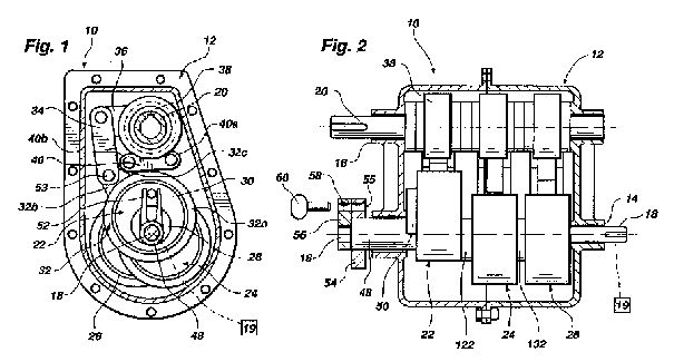
Gogins' transmission has two identical cams 180 degrees across from each other on the input shaft. The first pair of cams provides engine drive and the second pair of cams provides load drive. The first pair drives the output shaft and the second pair drives the engine for engine braking.
Output speeds are varied by moving a rack gear's power takeoff along cam-driven oscillating levers. When the PTO is at a pivot point, the output speed is zero and in principle, Fechner said, Gogins' transmission will have an infinite number of gear ratios.
Fechner added the transmission will lead to cleaner air and longer-lasting vehicles.
Gogins attended the University of Minnesota where he majored in physics. He taught countermeasures electronics in the U.S. Navy during World War II.
Gogins has interests outside the scientific field. He has invested a lot of his time supporting the arts.
Gogins founded the Contemporary Gallery and School of Arts around 1980. The gallery had concerts and exhibits.
Fechner was raised by Gogins from the time he was 8 years old. Growing up with Gogins, he said he ended up with a very interesting perspective on life.
"I was raised looking at the world with much bigger eyeballs," Fechner said.
Fechner said along with being an inventor, Gogins studied philosophy and was an accomplished artist.
He said working with Gogins has given him the opportunity to make things better.
"He taught me how to trouble-shoot and be able to apply those skills in different areas of my life," Fechner said. "I'm not an inventor, I've just picked up a variety of skills by helping him."
A constant power mechanical transmission with seamless, ripple free, infinitely variable torque multiplying outputs comprises an input shaft and an output shaft. The input shaft is coupled to a pair of oscillating levers whereby rotation of the input shaft causes oscillation of the oscillating levers in opposite directions. The oscillating levers are linked to the output shaft with one-way clutches in order to cause rotation of the shaft upon movement of the oscillating levers. The rotational speed of the output shaft can be infinitely varied by changing the throw of the oscillating levers.
BACKGROUND OF THE INVENTION
1. Technical Field
This invention relates to mechanical apparatus for changing the speed and torque of the output shaft of a prime mover relative to its input shaft. More specifically, this invention is directed to an apparatus for providing up to an infinite number of seamless, ripple free changes of speed and torque from a power source such as a gas or diesel engine, an electric motor, a jet engine, a steam engine, the crank of a bicycle, or the like.
2. Background Art
Historically, significant efforts have been directed to the provision of transmission assemblies adapted for changing the speed and torque of a power source. Many of these assemblies have involved the use of ratchet drives, eccentrically-oriented cam assemblies, and variable length lever arms. Representative of past efforts in this regard are the structures disclosed in the following issued patents: U.S. Pat. Nos. 629,389; 3,803,931; 4,630,830; 4,487,085; 6,068,570; 4,936,155.
For example, U.S. Pat. No. 629,389 discloses a bicycle in which it is stated, "The gear may be changed by substituting larger or smaller pulleys." Thus, one would have to get off the bike, take out his tool kit, take-off the pulleys and attach new and different pulleys to change gear ratios. Furthermore, U.S. Pat. No. 629,389 is a one speed transmission.
U.S. Pat. No. 4,936,155 discloses a transmission to provide constant power, speed changing and torque multiplication. The invention utilizes "a variable throw cam and cam follower system to provide ripple free output speeds and wide ranging torques." The cam follower wheel makes point contact with said cam. With this configuration, the cam follower of the present transmission makes line contact with the cam, thus limiting torque and power capacity.
U.S. Pat. No. 3,803,931 discloses "a variable speed transmission device comprises an output shaft rotated from a first eccentric member through unidirectional couplings", thus rippled output speeds.
In U.S. Pat. No. 4,487,085, "The cam is tapered from one end to the other to permit the gear ratio of the transmission to be varied in infinite increments by adjusting the position of the cam relative to the followers." Power must pass the power through a tiny point of contact greatly limiting the power capacity of the transmission.
In U.S. Pat. No. 4,630,839, "A bicycle having pivoted level pedal system (1, 2, 45) and lever arm length or gear ratio (speed) change devices (3, 4, 5, 6)" is disclosed.
The device of U.S. Pat. No. 4,630,839 does not provide any means for removing ripple and, therefore, cannot provide seamless, ripple free outputs.
U.S. Pat. No. 6,068,570 utilizes eccentrics 14 and 25 which it refers to as cams. The eccentrics 14 and 25 cannot provide ripple free outputs. Furthermore, the transmission of U.S. Pat. No. 6,068,570 does not provide means to produce an infinite number of output speeds.
Thus, it would be advantageous to provide an infinitely variable torque multiplying, substantially constant power mechanical transmission that produces ripple free outputs, requires fewer components to assemble, is easier to manufacture, is adaptable to any prime mover providing ease of shifting, allows power shifting under load, can provide compression braking and can handle substantially more power and torque than prior art transmissions.
SUMMARY OF THE INVENTION
The instant invention includes an input shaft journaled in a restraining support or housing, one or more oscillators, two or more output levers driven by one or more oscillators. The output levers are coupled to one-way clutches on the output shaft. The throw on the output levers is by selection and infinitely variable in order to change the rotational speed of the output shaft.
In one embodiment the oscillators, levers and their respective fulcrum blocks may be rotatably coupled on a concentric shaft slidably splined on the input shaft for axial displacement relative to the fixed location of power take-offs.
In another embodiment the output slides are moveable and the oscillators are not axially moveable.
In all embodiments the movement of the power take-off members may be self powered and self locking.
Various oscillator configurations are contemplated, related but not limited to a slidable member on slide guides, wherein oscillators are adapted for back and forth linear displacement of a member along the length of those guides.
In other embodiments an oscillator may be a cam wherein a single cam will drive two levers.
In yet further embodiments two drive cams, 180[deg.] apart, may drive the two power levers.
In another configuration, each cam drives its power lever while another cam is configured to keep the drive cam follower wheel in contact with the drive cam at all times.
In yet another configuration a spring is used to keep a cam or eccentric follower wheel in contact with the cam.
In another configuration a pair of rollers journaled on the power take-off ride on the lever while a spring holds the lever in contact with these rollers.
In another arrangement rack gears on the output slide drive a pinion gears integral with overrunning clutches journaled on the output shaft.
In some embodiments a single cam drives two cam followers 180[deg.] apart kept in contact with the cam by spring forces.
Likewise, the single cam may have an inner and an outer race, with one biasing cam follower wheel riding on the outer face and another cam follower wheel riding on the inner race with two cam follower wheels journaled on each independent axle.
The instant invention may be adapted to include structures for selectively applying vector longitudinal force generated by transmission power levers directly on the cam/follower assemblies thereby power shifting the assemblies along the length of a shaft on which they are mechanically associated.
In some embodiments the instant invention may include a control slide, constrained in a groove or along guide rails attached to the transmission housing, and integral with cam follower (oscillator) slide guides and fulcrum blocks connecting rods.
In some embodiments the control slide is contoured with grooves having oppositively oriented inclined planes wherein rollers biased in cages against the oppositely angled inclined planes in the grooves function as opposed linear one-way clutches to lock the control slide to the housing or to selectively bias the rollers by moving the cage one way or the other wherein the lever forces generated within the transmission may move the control slide one way or the other, thus providing power shifting and automatic clamping.
In another embodiment the one-way clutch cavities, rollers and cages may be in the power take-offs and automatically hold the power take-offs in selected positions or allow them to be moved by interior lever forces in one direction or the other on power levers.
Screw or hydraulic positioners or the like may be used to move or to hold the control slide.
One end of the cam driven lever provides zero output speed and maximum output torque. The other end of the lever, which may extend beyond the cam drive connection, provides the maximum output speed and a smaller output torque. Thus, the instant invention is an infinitely variable constant power transmission.
In another embodiment, by not including a moveable control slide, the transmission may be used as a low cost, power dense, one or two fixed speed reducer.
In yet another embodiment cam shaped links, sans cam followers, effectively remove ripple free selected output.


The variable speed transmission includes a power input drive shaft and a variable throw crank having a zero throw position aligned with the input shaft. The variable throw crank is coupled to the input shaft for rotation therewith and its eccentricity with respect to the axis of rotation of the input shaft can be varied. A control plate, also referred to as a master link, is rotatably mounted on the crank and a plurality of clutches having input and output shafts are operatively connected to the control plate through a plurality of pitman type links, whereby the control plate oscillates the input shafts of the clutches upon rotation of the power input shaft and variable throw crank of the transmission. The outputs of the clutches are connected to an output shaft for the transmission. By varying the throw of the variable throw crank the ratio between the rotary speed of the output shaft can be infinitely adjusted from zero to a maximum ratio determined by the maximum eccentricity of the variable throw crank with respect to the axis of rotation of the input shaft. A preferred embodiment is to revert the above.
The present invention relates to variable speed transmission devices and more particularly to a transmission device which is infinitely variable over a predetermined range.
The infinitely variable transmission of the present invention permits variation in speeds between the power input shaft to the transmission and the power output shaft, as well as torque multiplying and positive drive mechanical power transmission over an extremely broad range of speeds in either forward or reverse directions, from zero to several times the input speed. The output torque with the transmission of the invention is inversely proportional to the output speed with high efficiency throughout its entire range. And, in the transmission of the present construction, there is no apparent torque or power limit too large for the transmission to effectively handle.
Although infinitely variable transmissions have been previously proposed, such transmissions are relatively complex and require a large number of moving parts, such as shown for example in U.S. Pat. Nos. 3,803,931 and 3,229,549. By the construction of the present invention an infinitely variable transmission is provided which is smaller in size and formed of fewer and simpler parts as compared to previously proposed transmissions of this type. Moreover, the transmission is economical to manufacture and should be far easier to maintain than conventional transmissions it is intended to replace. It is believed that the use of this transmission in an automobile could double the automobile's mileage by allowing the automobile engine to operate at its more efficient fuel effective low speed high torque mode more often, regardless of vehicle speed. It also makes the single shaft Brayton engine practicel. In addition, the variable throw feature of the present invention can be used in other types of transmissions apart from auto transmissions of the type with which applicant is principally concerned herein and the novel clutch used in the transmission of the present invention is an important element by itself, and can be used apart from the transmission disclosed herein. In particular, this clutch element can serve as a slip clutch, indexing, overrunning, or centrifugal clutch in many applications. The clutch element does not rely on mechanical parts slipping against one another or jamming as in a sprag clutch, and therefore will be more durable in use.
In accordance with one aspect of the present invention a variable speed transmission is provided which includes a power input shaft and a variable throw crank rotatably mounted with respect to the power input shaft, but connected thereto for rotation with the shaft. The crank has a zero throw position aligned with the axis of rotation of the input shaft, and means are provided for varying the throw of the crank with respect to the power input shaft so that rotation of the power input shaft will cause the crank to rotate about its axis of rotation.
A master link or control plate is rotatably mounted on the crank and means are provided for preventing rotation of the plate on the crank while allowing the plate to move with the crank as the crank rotates within the plate. The transmission also includes a power output shaft and a plurality of clutches operatively connected between the control plate and the output shaft for transmitting power from the plate to the output shaft in response to movement of the plate about the axis of rotation of the power input shaft when the input shaft is rotated and the variable throw crank is out of axial alignment with the input shaft. As a result, the speed of rotation of the output shaft is varied with the eccentricity of the variable throw crank pin. The above described is reverted for many applications.
The above, and other objects, features and advantages of this invention will be apparent in the following detailed description of an illustrative embodiment thereof, which is to be read in connection with the accompanying drawings, wherein:

A transmission for providing continuously variable speed and torque comprises a housing, an input shaft, a system of variable throw eccentrics, control means for changing eccentric throw of the variable throw eccentrics, connecting links for receiving eccentric throw from the system of variable throw eccentrics and transmitting it as reciprocal motion and removing ripple from the output, one-way clutches for receiving reciprocal motion from connecting links and transmitting it as rotational motion, and an output shaft. The control means comprise a control shaft rotatably disposed around the input shaft so that both shafts have the same rotational axis and with a fork fixed to the control shaft, a pin fixed at one end to an eccentric and engaged between the prongs of the fork, and means for rotating the control shaft with respect to the input shaft, thus changing the eccentric throw and the transmission ratio. Reversible and nonreversible hydraulic one-way clutches, means for reversing rotation of the output shaft, and means for compression braking are also within the scope of the invention.
BACKGROUND OF THE INVENTION
This invention relates to a transmission for and a method of changing speed and torque from an input power source. More particularly, the invention relates to a transmission for and a method of selecting from an "infinite" number of output torques and speeds, from maximum to as low as zero output speed, for vehicles, industrial speed changers, and the like, wherein ripple, or variation in rotational speed induced by crank action, is removed from the output.
Numerous devices and methods have been devised to change the speed and torque from a prime mover. One category of such devices and methods involves variable and fixed speed transmissions known as ratchet drives. Transmissions of this type include those that contain variable thro cranks, variably displaced fulcrums, and variable length lever arms.
An example of a variable throw system is described in U.S. Pat. No. 3,915,129 by Rust. In this device, a timing cam, with a distance from axis of rotation to cam surface that varies along its axis of rotation, is used to vary valve operating characteristics as a function of the position of a cam follower along the axis of rotation of the cam. Examples of other such devices have been described in U.S. Pat. No. 3,915,129; U.S. Pat. No. 3,229,546; U.S. Pat. No. 2,159,739; Italian Pat. No. 460047; and French Pat. No. 590,087.
Transmissions usually have fixed gear ratios that, although suitable for many uses, may be inadequate when the speed or torque needed is not efficiently provided by available gear ratios. For example, if the lowest gear ratio provided by a transmission having certain fixed gear ratios does not provide sufficiently low speed or sufficiently high torque for a given application, then the transmission is not suitable for the job. Thus it would be advantageous to provide a transmission that can furnish an infinite number of gear ratios and, consequently, an infinite number of output speeds and torques, between zero and some maximum.
Another problem associated with many transmissions is that shifting between gear ratios involves loss of power. Shifting gears while driving a motorized vehicle uphill illustrates this problem, inasmuch as the loss of power associated with shifting gears rapidly results in a loss of momentum. Thus, it would be advantageous to provide a transmission that could be shifted between an infinite number of available gear ratios without interrupting output power.
Additionally, many industrial machines are powered by constant speed electrical motors. Thus, it would be desirable to provide an industrial speed changer that can provide a wide variety of output speeds and torques. Because of the large variety of uses for such speed changers, it would be desirable to have a family of industrial speed changers that could fit the many needs for them, yet that could be manufactured from a few identical parts.
Certain applications require wide ranges in transmission gear ratios, such as in certain types of bicycles. Since a human does not generate much power except at certain pedaling speeds, it would be advantageous to provide a transmission that, efficiently furnishes a wide range of selectable gear ratios to allow for increased speed and distance for the same or less effort.
It would also be advantageous to provide a transmission that is inexpensive to build, yet reliable. Such a transmission would be suitable for many different kinds of vehicles, from bicycles to motorized vehicles such as cars, trucks, buses, trains, tractors, and the like.
Also, a transmission that is light in weight and has a wide range of transmission ratios would not only provide improved fuel economy, but also improved acceleration and hill climbing ability.
OBJECTS AND SUMMARY OF THE INVENTION
It is an object of the present invention to provide a transmission or torque-multiplying, constant power speed changer that is inexpensive, reliable, and can supply an infinite number of speed ratios and be easily shifted.
It is also an object of the invention to provide a low cost, light weight vehicular transmission that, because of its wide ratio range, improves fuel economy, acceleration, and control ability of land, air, and water vehicles.
It is another object of the invention to provide a low cost industrial speed changer that can be driven by a constant-speed motor and efficiently provide a wide variety of output speeds and torques.
It is a further object of the invention to provide a transmission with a wide ratio range and high efficiency that would be suitable for use in a bicycle.
These and other objects may be realized in an illustrative embodiment of a transmission comprising a housing, a rotatable input shaft for receiving a rotational input having a certain speed, one or more variable throw eccentrics longitudinally disposed on the input shaft, a mechanism for selectively changing eccentric throw of the eccentrics between a minimum throw (which may be zero) and a maximum throw, a rotatable output shaft for providing a rotational output having selected speeds and torques, one or more one-way clutches mounted on the output shaft, and connecting links coupled between the eccentrics and the clutches for transmitting motion from the eccentrics to the clutches to, in turn, cause rotation of the output shaft and for removing ripple from the output. Ripple is removed from the output shaft speed
by guiding the connecting links in selected paths to effectively change the lengths and motion of certain links so that rotation of the clutches is slowed or accelerated during certain phases of rotation to provide constant output speeds of the output shaft, at desired transmission ratios.
Novel hydraulic one-way clutches may be utilized to drive the output shaft as the clutches rotate in one direction, and rewind as the clutches rotate in the opposite direction. Output rotation may be reversed by use of a reversible hydraulic clutch, by a spur gear differential, or by other methods.
The transmission of the present invention may be used to provide compression braking for an engine driven vehicle by mounting the transmission in the opposite orientation to the drive train of the vehicle .


The variable speed transmission includes a power input drive shaft and a variable throw crank having a zero throw position aligned with the input shaft. The variable throw crank is coupled to the input shaft for rotation therewith and its eccentricity with respect to the axis of rotation of the input shaft can be varied. A control plate, also referred to as a master link, is rotatably mounted on the crank and a plurality of clutches having input and output shafts are operatively connected to the control plate through a plurality of pitman type links, whereby the control plate oscillates the input shafts of the clutches upon rotation of the power input shaft and variable throw crank of the transmission. The outputs of the clutches are connected to an output shaft for the transmission. By varying the throw of the variable throw crank the ratio between the rotary speed of the output shaft can be infinitely adjusted from zero to a maximum ratio determined by the maximum eccentricity of the variable throw crank with respect to the axis of rotation of the input shaft. A preferred embodiment is to revert the above.
The present invention relates to variable speed transmission devices and more particularly to a transmission device which is infinitely variable over a predetermined range.
The infinitely variable transmission of the present invention permits variation in speeds between the power input shaft to the transmission and the power output shaft, as well as torque multiplying and positive drive mechanical power transmission over an extremely broad range of speeds in either forward or reverse directions, from zero to several times the input speed. The output torque with the transmission of the invention is inversely proportional to the output speed with high efficiency throughout its entire range. And, in the transmission of the present construction, there is no apparent torque or power limit too large for the transmission to effectively handle.
Although infinitely variable transmissions have been previously proposed, such transmissions are relatively complex and require a large number of moving parts, such as shown for example in U.S. Pat. Nos. 3,803,931 and 3,229,549. By the construction of the present invention an infinitely variable transmission is provided which is smaller in size and formed of fewer and simpler parts as compared to previously proposed transmissions of this type. Moreover, the transmission is economical to manufacture and should be far easier to maintain than conventional transmissions it is intended to replace. It is believed that the use of this transmission in an automobile could double the automobile's mileage by allowing the automobile engine to operate at its more efficient fuel effective low speed high torque mode more often, regardless of vehicle speed. It also makes the single shaft Brayton engine practicel. In addition, the variable throw feature of the present invention can be used in other types of transmissions apart from auto transmissions of the type with which applicant is principally concerned herein and the novel clutch used in the transmission of the present invention is an important element by itself, and can be used apart from the transmission disclosed herein. In particular, this clutch element can serve as a slip clutch, indexing, overrunning, or centrifugal clutch in many applications. The clutch element does not rely on mechanical parts slipping against one another or jamming as in a sprag clutch, and therefore will be more durable in use.
In accordance with one aspect of the present invention a variable speed transmission is provided which includes a power input shaft and a variable throw crank rotatably mounted with respect to the power input shaft, but connected thereto for rotation with the shaft. The crank has a zero throw position aligned with the axis of rotation of the input shaft, and means are provided for varying the throw of the crank with respect to the power input shaft so that rotation of the power input shaft will cause the crank to rotate about its axis of rotation.
A master link or control plate is rotatably mounted on the crank and means are provided for preventing rotation of the plate on the crank while allowing the plate to move with the crank as the crank rotates within the plate. The transmission also includes a power output shaft and a plurality of clutches operatively connected between the control plate and the output shaft for transmitting power from the plate to the output shaft in response to movement of the plate about the axis of rotation of the power input shaft when the input shaft is rotated and the variable throw crank is out of axial alignment with the input shaft. As a result, the speed of rotation of the output shaft is varied with the eccentricity of the variable throw crank pin. The above described is reverted for many applications.
The above, and other objects, features and advantages of this invention will be apparent in the following detailed description of an illustrative embodiment thereof, which is to be read in connection with the accompanying drawings, wherein:


The power transmission is a hydromechanical torque multiplier that is infinitely variable over its operating speed range. It comprises relatively few components, and is highly efficient in its operation. Close control of the output torque and speed is readily accomplished. The torque multiplication and enhancement between the power input and its output drive is a significant feature of the transmission hereof. It may be constructed for small power operation, as well as for hundreds of horsepower.
BACKGROUND AND SUMMARY OF THE INVENTION
The power transmission requires only hydraulic pumping, and no hydraulic motor. It is thus smaller, lighter in weight, and more economical than prior hydrostatic transmissions. Further, at the high speed ratio of 1:1 no oil is pumped therein. Such arrangement improves operating efficiency. There is no input to output coupling across hydraulic fluid, and oil heating losses are greatly reduced.
The invention transmissions are quieter in operation, and less subject to wear or mal-adjustment. They span a wide variety of advantageous applications, as: industrial variable speed drives; snowmobile and vehicular transmissions; bicycle multi-speed transmissions. In a snowmobile for example, its compactness effects the replacement of the roller chain drive now in general use, saves space, and lowers the center-of-gravity of the snowmobile.
The invention device is a torque converter which comprises an input shaft, siphon means associated therewith for feeding oil from a sump through to a pump, and the oil is ejected as a jet from a nozzle. The oil jet issuing from the nozzle impinges upon circumferentially arranged buckets which reverse the flow direction so as to impinge upon a runner vane. The reversing buckets lie axially between the nozzle and the vane. The runner vane is secured with the nozzle structure whereupon cumulative torque is derived that is added to the input torque. A valve is utilized to control the oil flow from the nozzle. The pump may be a vane type, piston type, or equivalent. The output drive may be gearing about the pump housing, or gears combined with an external housing of the transmission. The latter arrangement is particularly useful as a snowmobile transmission, as will be described.


A variable transmission having an input shaft, a lobed cam slidably splined on said shaft, and a plurality of pivotedly mounted cam followers which mechanically engage the cam is disclosed. The cam follwers are connected to an output shaft through intermediation of a one-way clutch mechanism. Each cam follower includes a steerable contact member whose orientation may be modified to induce a coaxially directioned, displacing force on the cam. The displacement of the cam effects a shifting of the transmission ratio.
BACKGROUND OF THE INVENTION
1. Field of the Invention
The present invention relates generally to apparatus and methods for changing speed and torque from a prime mover. More particularly, the invention pertains to apparatus and method for selecting infinite speed and torque variations for vehicles, wind turbines and industrial speed changers through selected use of a variable throw cam designed to smoothly produce selected, ripple-free speeds and torques.
2. Statement of the Art
Numerous systems and methods have been proposed to change the speed and torque from a prime mover. The present invention relates generally to that class of variable and fixed speed transmissions described as ratchet drives and more particularly to the control mechanisms employed with such drives. Transmissions of this type, known previously, include variable throw eccentrics, variably displaced fulcrums and/or variable length lever arms adapted to produce speed variations. Such systems are shown, for example, in U.S. Pat. No. 3,803,931; U.S. Pat. No. 3,517,913; U.S. Pat. No. 3,229,549; U.S. Pat. No. 3,073,173; U.S. Pat. No. 2,199,052; U.S. Pat. No. 2,159,739; U.S. Pat. No. 3,915,129; Italian Patent No. 460047 and French Patent No. 590,087.
Some of these known systems utilize planetary arrays of one-way clutches while others utilize in-line arrays. Various means of selecting the input-output ratios of the systems have been proposed.
Another known transmission is shown in U.S. Pat. No. 4,116,083. This transmission reverts the power train so that the common shaft is an input shaft instead of an output or stator shaft. In this transmission, the housing operates as the output member.
U.S. Pat. No. 1,770,132 (Van Soden-Fraunhofen) discloses a gear system having cam followers positioned to ride atop a cam turned by an input shaft. A lateral movement of the input shaft displaces the followers on the cam to change the drive ratio between input and output shafts.
U.S. Pat. No. 1,954,767 (Foster) discloses a variable speed transmission wherein a cam is moved to change speed ratio and wherein followers ride on the cams.
U.S. Pat. No. 2,554,463 (Klamp) discloses a variable speed transmission having a plurality of cam followers arranged in a substantially circular spacing about a cam.
Klamp suggests positioning the cam followers such that alternate followers are simultaneously rotated in a common direction during the same time period that the remaining cam followers are rotated in an opposite direction. This interrelationship facilitates the connection of adjacent pairs of cam followers by tension springs which act as a means of retaining the cam followers in contact with the cam.
U.S. Pat. No. 2,983,154 (Neukirch) suggests a variable speed mechanical transmission having a plurality of cam followers spacedly positioned about a centrally positioned cam. Neukirch discloses housing-mounted springs which abut against the cam followers and urge them into engagement against the cam. In one embodiment (FIG. 10), Neukirch suggests the placement of a roller on the cam follower.
U.S. Pat. No. 3,803,931 (Bianchini et al.) discloses a variable speed transmission having two sets of cam followers positioned in a substantially circular, spaced orientation about a central cam. A set of cam followers is shown positioned on each of the opposing sides of the disc-like cam.
U.S. Pat. No. 4,487,085 (Collins) discloses an infinitely variable transmission wherein a cam follower includes a rotatably mounted roller which is mounted within a yoke formed within the cam follower.
In applicant's co-pending U.S. Pat. application, Ser. No. 753,044, filed July 2, 1985, applicant has disclosed an Infinite Speed Variation, Constant Power, Ripple-Free Transmission. The disclosed transmission uses a multi-lobed cam, rotatably mounted on a shaft. Followers, positioned to engage the cams, transmit the rotation of the cams to another shaft through use of one-way clutches.
While the gearing systems and transmissions described in the foregoing devices have proven desirable for use, it has been found that such devices do not always permit easy, smooth shifting to allow for effective selection of the infinite gear ratios available with the devices.
SUMMARY OF THE INVENTION
The instant invention provides a generally inexpensive, reliable, and infinitely variable, easily and smoothly shifted transmission or torque-multiplying speed-changing device system.
To provide constant power, speed changing and torque multiplication, the invention utilizes a variable throw cam and cam follower system to provide ripple-free output speeds and wide ranging torques. One end of the cam lobe has zero throw. The opposite end of the cam lobe has maximum throw. There are an indefinite number of different throws between these extremes.
A unique control means of the invention provides a smooth, easy shifting of cams under the cam followers and under load of a type described herein. In one embodiment of the invention, the followers are mechanically associated with the cam surfaces by a structural member which provides a steerable anti-friction rolling action of the followers over the cam surfaces, while the cam is longitudinally displaced under the axially fixed follower(s) and while the cam turns under the follower(s).
Alternatively, the cam may be axially fixed and the followers slidably splined onto the input shaft so that they can be slidably displaced. In this alternative embodiment, a similar structural member provides a steerable, anti-friction rolling action association of the cam followers vis-a-vis the cam. The control means provide even minute displacement of the cams longitudinally beneath the followers.
The invention provides an automatically controlled transmission suitable for varying the propeller speed of a wind turbine (the propeller being the prime mover). The invention may also be used to provide an optimum propeller speed for each wind speed, to selectively stall the propeller by slowing it down in higher wind speeds. This permits maximum generator output to be maintained but not exceeded at these higher speeds, thereby increasing the energy output of wind turbines.
The invention also provides an easily and smoothly shifted transmission suitable for use with a bicycle that, because of its wide ratio range and high efficiency, will allow a bicycle rider to travel further and faster while using a minimum amount of energy.
Additionally, the invention provides a smoothly shifted industrial speed changer that can, while being driven by a low cost, efficient, electrical motor, efficiently provide a wide variety of output speeds, with output torque increasing while output speeds decrease.
The invention provides a smoothly shifted vehicular transmission that can, because of its wide ratio range, greatly improve fuel economy and acceleration for cars, trucks, buses, trains, tractors and planes.
Additionally, the invention provides a large family of low cost, efficient,fixed ratio industrial speed changers whose fixed ratios can be changed if necessary. A multiple variety of these fixed ratio speed changers can be made from a few identical parts.
Structurally, the instant invention includes an input shaft journaled in a retaining housing. A lobed cam is splined on the input shaft and adapted for sliding displacement along a length of that shaft. One or more cam followers are pivotedly mounted and axially constrained to the retaining housing or, alternatively, to an output shaft journaled in the retaining housing and held in a spaced relationship with the cam. Various orientational arrangements of the cam followers relative to the cam are within contemplation. For example, some embodiments position the cam followers linearly in tandem along the length of the cam. Other embodiments, for example, utilizing two, three, four or more cam followers, position the cam followers in a generally spaced circular arrangement about a centrally positioned cam. In an embodiment having multiple output shafts, cam followers associated with a common output shaft may be arranged in tandem. The groups of tandemly arranged cam followers, each group having its respective output shaft, are positioned about a centrally positioned cam, e.g., in a generally spaced circular arrangement.
In this alternative embodiment, the cam is axially fixed to the input shaft. Whereas in the first embodiment the cam is displaced relative to axially fixed cam followers, in this alternative embodiment the cam followers are displaced relative to an axially fixed cam.
Alternatively, one or more cam followers are splined on the output shaft and adapted for sliding displacement along a length of that shaft. Each cam follower is urged into a mechanical engagement against the cam by a biasing means. Various types of biasing means are contemplated within the scope of the invention. Of those disclosed, one such means relies on the mechanical characteristics of compressed springs; a second biasing means utilizes an arrangement of hydraulically actuated, piston-fitted cylinders oriented to direct a force against each of the respective cam followers, thereby urging those followers into a mechanical engagement with the cam.
Each cam follower is fitted with a cam contact member (hereinbefore described as a structural member) which may be a rotatably mounted wheel or anti-friction roller which is positionable to engage and ride upon the cam. The contact member may be mounted to be steerable, i.e., the wheel's orientation, i.e., its axis of rotation, relative to the structure of the cam follower may be altered. This steerability permits the cant or orientation of the roller, relative to the cam surface on which it rides, to be changed. A given alteration to the orientation of the wheel's axis of rotation induces longitudinal, axially directed forces on both cam follower and the cam itself. In those embodiments having a displaceable cam, these forces effect a displacement of the cam along the input shaft relative to the follower(s). In those embodiments having displaceable followers, the followers are displaced by the force. In both embodiments, the fixedly-mounted cam follower or cam remains axially stationary. The resulting displacement of the cam in the first embodiment or the cam followers in the second embodiment effects a change in the throw of the cam follower(s) as the rotating cam is passed beneath the cam follower(s) during the cam's displacement. The rim of the follower wheel never slides on the cam while speed ratios are changed.
The invention discloses a steering means for controlling or alternatively, maintaining the contact member's orientation. This steering means may be actuatable externally from the transmission itself.
Furthermore, the invention may include a control system which includes a feedback mechanism for interrelating the steering means with the actual position of the cam at any given time. After the cam follower contact member has been steered and the cam is thereby forcedly displaced to a desired location, the feedback mechanism operates to reorient the cam follower contact member to an equilibrium orientation, thereby reducing and eliminating any axially directed force application to the cam by the contact member at the selected ratio.
The cam followers mechanically engage an output or reaction shaft by means of one or more one-way clutches. Although various types of such clutches may be utilized in the invention, e.g. sprag or roller type one-way clutches, the invention may further include my unique hydraulic one-way clutch. This hydraulic one-way clutch includes a rotor which is fixedly mounted on an output shaft. The rotor is rotatably mounted within the hollow cavity of a ring housing which, in turn, may be the hub of a respective cam follower. The rotor is spacedly positioned from the interior wall of the ring housing, which housing defines an oblate cavity therein. A plurality of extendible vanes are biasedly mounted within channels recessed into the structure of the rotor. An auxiliary channel communicates with each recess channel as well as the innermost part of each vane. Each auxiliary channel furthermore communicates with the exterior of the rotor between each pair of vanes. The auxiliary channels are adapted to selectively receive pressurized fluid and direct that fluid against the innermost part of the respective vanes and thereby forcefully displace those vanes from within their respective recess channels outward toward the ring housing, cavity-defining interior wall.
The vanes are adapted to abut against the interior wall and thereby subdivide the space extant between the rotor and the interior wall into a plurality of wedge-shaped cross-sectioned subchannels. Upon a rotation of the rotor in a first direction, the configuration of the annular channel and the plurality of subchannels creates a high oil pressure within a plurality of the subchannels as the rotor's rotation causes the spatial volume of some of those subchannels to decrease. The resulting hydraulic pressure creates essentially a hydraulic or pressure linkage of the rotor with the ring housing whereby a corresponding rotation of the rotor in the first direction causes a rotation of the ring housing in the same direction or vice versa. The outmost parts of the vanes are configured so as not to include surface areas on which an imposition of directed forces, by the described hydraulic pressures, would induce a return of the vanes back into their respective recess channels within the rotor. When the rotor is rotated in the opposite direction, the ends of the vanes, due to their configuration, provide a surface on which the increasing oil pressure can act, there-by pushing the vanes into the rotor, and dismantling the subchannels and eliminating the linkage between the rotor and ring housing. This occurs since there is no auxiliary channel from the other side of the vane to allow oil pressure in under that vane. Absent the linkage, the rotor turns freely in the ring housing cavity with no related rotation of the ring housing. Note that the ring housing cavity is kept filled with oil through make-up passages leading from a lower pressure oil supply source. The oil is filtered during operation by a filter between the high pressure and low pressure areas of the clutch. A check valve precludes oil from flowing out of the high pressure area while permitting flow through the filter into that area.
It should be clear that the rotor could be the driving member and the housing the driven member of this clutch, or vice versa.
Previous cam and cam follower variable transmissions have varied the speed and/or torque of an output shaft by applying heavy displacing forces directly on the cam, thereby displacing it along the length of the input shaft. The instant invention effects such a cam displacement by reorienting the cant of the cam follower contact member. The rolling action of the cam follower on the cam induces an axially directed force on the cam which displaces the cam longitudinally along its support shaft and relative to the cam follower. In a first embodiment, the followers remains longitudinally fixed relative to the cam throughout the transmission's operation. In a second embodiment, the cam followers are made longitudinally displaceable by the reorientation of the contact member while the cam is longitudinally fixed.
Two embodiments of a control screw having a feedback means associated therewith adapted for interrelating the orientation of the cam follower contact member and the cam are disclosed. One construction utilizes a pivoted feedback linkage which mechanically relates the cam with a nut mounted on the control screw. A given displacement of the cam operates to induce a measured displacement of the control screw. A second control embodiment makes use of a hydraulic flow valve to control hydraulic pressure to a piston-fitted cylinder to interrelate cam displacements with a follower contact member reorientation.


The variable speed transmission includes a power input drive shaft and a variable throw crank having a zero throw position aligned with the input shaft. The variable throw crank is coupled to the input shaft for rotation therewith and its eccentricity with respect to the axis of rotation of the input shaft can be varied. A control plate, also referred to as a master link, is rotatably mounted on the crank and a plurality of clutches having input and output shafts are operatively connected to the control plate through a plurality of pitman type links, whereby the control plate oscillates the input shafts of the clutches upon rotation of the power input shaft and variable throw crank of the transmission. The outputs of the clutches are connected to an output shaft for the transmission. By varying the throw of the variable throw crank the ratio between the rotary speed of the output shaft can be infinitely adjusted from zero to a maximum ratio determined by the maximum eccentricity of the variable throw crank with respect to the axis of rotation of the input shaft. A preferred embodiment is to revert the above.purposes.
The present invention relates to variable speed transmission devices and more particularly to a transmission device which is infinitely variable over a predetermined range.
The infinitely variable transmission of the present invention permits variation in speeds between the power input shaft to the transmission and the power output shaft, as well as torque multiplying and positive drive mechanical power transmission over an extremely broad range of speeds in either forward or reverse directions, from zero to several times the input speed. The output torque with the transmission of the invention is inversely proportional to the output speed with high efficiency throughout its entire range. And, in the transmission of the present construction, there is no apparent torque or power limit too large for the transmission to effectively handle.
Although infinitely variable transmissions have been previously proposed, such transmissions are relatively complex and require a large number of moving parts, such as shown for example in U.S. Pat. Nos. 3,803,931 and 3,229,549. By the construction of the present invention an infinitely variable transmission is provided which is smaller in size and formed of fewer and simpler parts as compared to previously proposed transmissions of this type. Moreover, the transmission is economical to manufacture and should be far easier to maintain than conventional transmissions it is intended to replace. It is believed that the use of this transmission in an automobile could double the automobile's mileage by allowing the automobile engine to operate at its more efficient fuel effective low speed high torque mode more often, regardless of vehicle speed. It also makes the single shaft Brayton engine practicel. In addition, the variable throw feature of the present invention can be used in other types of transmissions apart from auto transmissions of the type with which applicant is principally concerned herein and the novel clutch used in the transmission of the present invention is an important element by itself, and can be used apart from the transmission disclosed herein. In particular, this clutch element can serve as a slip clutch, indexing, overrunning, or centrifugal clutch in many applications. The clutch element does not rely on mechanical parts slipping against one another or jamming as in a sprag clutch, and therefore will be more durable in use.
In accordance with one aspect of the present invention a variable speed transmission is provided which includes a power input shaft and a variable throw crank rotatably mounted with respect to the power input shaft, but connected thereto for rotation with the shaft. The crank has a zero throw position aligned with the axis of rotation of the input shaft, and means are provided for varying the throw of the crank with respect to the power input shaft so that rotation of the power input shaft will cause the crank to rotate about its axis of rotation.
A master link or control plate is rotatably mounted on the crank and means are provided for preventing rotation of the plate on the crank while allowing the plate to move with the crank as the crank rotates within the plate. The transmission also includes a power output shaft and a plurality of clutches operatively connected between the control plate and the output shaft for transmitting power from the plate to the output shaft in response to movement of the plate about the axis of rotation of the power input shaft when the input shaft is rotated and the variable throw crank is out of axial alignment with the input shaft. As a result, the speed of rotation of the output shaft is varied with the eccentricity of the variable throw crank pin. The above described is reverted for many applications.

VARIABLE SPEED TRANSMISSION
CA1130736 // CA1106645
CA1130736 // CA1106645