Christian GRANIER
X-Ray Weapon
X-Ray Weapon
Related : GRINDELL-MATTHEWS : "Death Ray" ** HOLLINGSHEAD : Odic Ray ** MOHR : Detonator Ray ** VAIDEANU : UV-RF Ray ** CURRY : Atmospheric Plasma Generator ** CORNWELL : Microwave Phenomena ** FORTOV : Microwave EMP Generator **
FR2869682
X-Ray Weapon
X-Ray Weapon
Weapon for remotely destructing electric materials, electronic circuits and configuration of e.g. computer, has anticathode to create hard X ray beams passing through cathode and directed to focal point of system to be destructed.
The weapon has two guns (5, 6), each with a heating filament (13) to heat a cathode (14), supplied with very high negative voltage (11), for extracting electrons (15) when the weapon assembly is supplied with voltage. The electrons are reflected by an anticathode (19) to generate concentrated hard X-ray beam (16) that passes through the cathode and is directed towards a focal point of a system to be destructed. The electrons are attracted by an anode (20) supplied by very high positive voltage (11).
DESCRIPTION
The present invention relates to a weapon whose device according to the invention allows remote destruction of all electrical equipment, electronic circuits and all computer configurations in order to render unusable the equipment for which they were designed.
As a result, destruction involves all equipment and installations using and using such electrical equipment, electronic circuits and X10 computer configurations, whether stationary or mobile, land, air or sea, such as computers, navigation and guidance systems , telecommunications, conventional or nuclear defense or attack weapons, aircraft, helicopters, land vehicles, missiles, satellites, rockets, boats, detection devices, radars, electricity, video systems, radio and television transmitters and receivers.
This weapon, whose device allowing such destruction, can be fixed or mobile, that is to say it can be used from a building, a dwelling, a land vehicle, an airplane , a helicopter, a ship, a rocket, a missile, or on the back of a man. This weapon can therefore be used anywhere and anywhere when thanks to its mobility. The neutralization of the circuits and configurations mentioned above takes place at the speed of light.
The range and power of this remote weapon of destruction, which is the subject of the invention, can be from a few meters to several tens of meters or hundreds of meters. The size of this weapon can be the size of a point weapon up to several meters. In fact, the size, scope and power of this weapon will be a function and will be defined by the specifications established for a specific device, for the use to be made of it and will therefore be essentially based on the the quality of the materials and components used, the energy available for its operation and to achieve the desired result. For example, the weapon being the device according to the invention, will be able, from the ground, from a helicopter or from a boat and by its user targeting an objective, an apparatus, to generate destruction of all the electronic circuits or embedded computing configurations and make this device unusable.
The present invention is a device for sending an electrical discharge at a distance to the speed of the light without material support, such as electric wires for example, in order to destroy remotely electronic circuits and the electronic components which constitute them or else still computer data. [4]
In the current state of technology, no device can achieve such a result and can not produce the shutdown without any physical or physical link, computer configurations, electronic circuits, electrical equipment.
The technical solution is provided by this weapon, which is the subject of the invention. To generate destruction of all circuits, equipment and computer, electronic or electrical configurations, they must be subjected to an electrical overload or discharge sufficient to cause the short circuits, the flashings necessary to render them definitively unusable.
If a direct or direct electrical or electrical overload or discharge is generated remotely, in the immediate environment in which these apparatuses, circuits and configurations are located, it occurs in these same devices, circuits or configurations , the overload or electrical discharge sufficient and fatal, provoking short circuits the flashings necessary to destroy them.
Science, calculations, tests, various experiments carried out, simulations and the laws of optics and physics, demonstrate several facts: a sufficient electrical overload or discharge causes, by induction, an electrical overload or discharge which is also fatal to the electrical or electronic circuits, as long as the latter are in the environment, the field and in the immediate immediate vicinity of the field generating the initial electrical overload or discharge.
An ionized atmosphere is conductive, transports electric charges, and behaves like an electrical conductor; therefore, when an electronic circuit, computer configuration and electrical equipment are found to be present in such an ionized atmosphere, to which an overload or an electric discharge is applied, by induction, there is a sufficient overload or electrical discharge and fatal to these same circuits and configurations, generating the destruction of the electronic components and the computer data.
X-rays have the particularity of ionizing the atmosphere they pass through. This ionized atmosphere allows the transport of electric charges as would an electrical conductor. It is therefore possible to apply an overload or an electric discharge of very high voltage from an electric generator to this atmosphere ionized by X-rays. The basic principle will therefore be that, for the device according to the invention, electrical equipment, electronic circuits and computer configurations by hard X-rays in order to locally cause an ionization of the atmosphere in which the circuits and materials mentioned above are located; The electrical overload or discharge must then be applied to the entire ionized atmospheric zone so that, by induction, generated in the said circuits, equipment, apparatus and configurations, the electrical overload or discharge necessary for their destruction.
X-rays have the peculiarity, since they are emitted, that they can not be deflected by any means, electric, waveguide or magnetic. Their direction, direction and field are defined as soon as they are produced and their trajectory can not be modified.
In order to allow these X-rays to have the direction, the direction A0 in a desired very closed angle and to be very concentrated in the form of beams, beams, much like a laser beam, allowing the production of X-rays from the outset; it is a question of modifying the anticathode, the AS cathode and the anode, in order to obtain highly concentrated hard X-rays having the desired shape, range and power, ie having a direction, a rectilinear direction very localized in the form of beams, as if it were a laser beam and having the least possible dispersion outside the chosen axis of X-ray propagation. For example , as soon as they are produced, the X-rays must have a diameter of between two centimeters and twenty centimeters, depending on the shape of the electrodes ZS * producing these electromagnetic waves and a range and power up to several hundred meters.
This will depend on the specifications established between the manufacturer and the user.
By combining at least two such hard x-ray sources of this type, directed in a convergent manner and in such a way as to create a focal point, the latter, for example, one hundred meters away, the whole atmospheric zone starting from the first source of production of X-rays to the focal point and then from the latter to the second source of production of X-rays will be ionized. At this ionized atmospheric zone subjected to X-rays, there can be applied an electric overload or discharge of very high voltage, coming from an electric source, from a few tens of thousands of volts to several hundreds of thousands of volts. As in an electrical conductor, electrical overload or discharge will extend over and throughout the ionized atmospheric zone from the first source of X-ray production to the focal point and then to the second source of X-ray production. If at the focal point or A0 in the trajectory of one of the two sources of X-ray production traversed by the electric discharge there is present an electronic circuit, a computer configuration, the latter will undergo the destructive electric discharge or overload created by induction by the initial electrical charge applied to the ionized zone.
In summary, two hard X-ray beams converge towards a focal point targeting an electronic circuit or a computer configuration; the entire atmospheric zone traversed by hard X-rays is ionized. At this ionized zone, a continuous, pulsed or alternating electrical discharge is applied which, by induction, causes an electrical overload in the electronic circuit which destroys the latter.
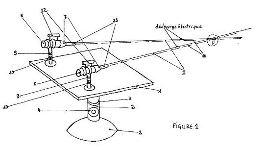
In its practical realization, the basic principle, the weapon 2S of remote destruction computer configurations, the invention, is a device of electronic circuits, electrical equipment, according to the following constituted: A mechanically removable plate (1) 2) of articulations, horizontal (3) and directional, linked by two vertical (4) stabilization in order to: enable spatial orientation of the whole object device and according to the invention.
On this tray (1) lies two hard X - ray guns (5 and 6) (16). Each of these barrels (5 and 6) is provided with a lead shield (7) to stop the residual X-rays. Each of these two barrels (5 and 6) is also equipped with a cooling radiator (8). Each bundle, lead (7) and radiator (8) on the one hand and barrel (6), lead (7) and radiator (8) by two degrees S of articulation, horizontal (9) and vertical (10) so as to be able to direct each beam of hard X-rays (16) emitted simultaneously by each of the two guns (5 and 6) converging towards a focal point (F). It is the set of adjustable joints (3), (4), (9), (10) 40 that will make it possible to target, designate and determine the objective to be achieved, corresponding to the focal point that is to say the electronic circuit or the computer configuration to be destroyed and housed in an apparatus such as an aircraft, a ship, a missile, a computer, etc.
Each of the hard X-ray generating guns (16 and 16) is independent of each other and are both spaced apart from a few centimeters to a few meters the specifications defined between the user and the manufacturer. The two X-ray beams (5 and 6) are produced identically.
Each gun (5 and 6) is supplied by a very high voltage electric current source (11) from a few thousand volts to a few hundred thousand volts 2S in order to produce very penetrating hard X-rays (16) required for operation of the weapon, which is the subject of the invention.
The whole device contains a whole set of points, fastenings, fasteners, locks and clamps, various supports (12).
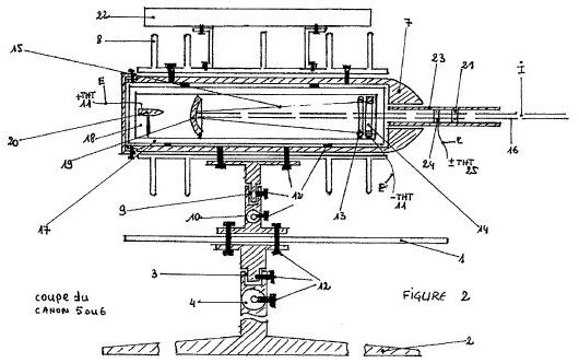
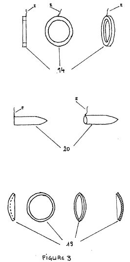
Each of the hard X-ray generating guns (5 and 6) is constructed and constructed identically of the other as follows: A resistant and sealed glass bulb (17) in the form of cylindrical tube, in which a very high air gap (18) has been produced; a metal cathode (14) supplied with a very high negative voltage (11), and in the form of a ring in order to allow the hard X-rays (16) emitted in the form of beams or rays to pass freely through the metallic anticathode 19).
The anticathode (19) has a parabolic shape so that the hard X - rays (16) are reflected along the axis and direction, the anode (20), the parabolic anticathode (19) ring and the focal point (F).
The precise form of the parabolic anticathode (19) will be defined according to the laws of optics and physics and the specifications established between the user and the manufacturer in order to allow a reflection from their source of X-rays (16) in a parallel manner under the beam shape SIS so that they can pass through the center of the circular cathode (14).
Each filament (13) of each barrel (5 and 6) is supplied with electric current so as to heat each cathode (14) of each barrel (5 and 6) in order to extract the electrons (15).
The metal anode (20) is supplied with a very high positive voltage (11) so as to attract the electrons (15) emitted by the cathode (14). The shape of the anode (20) should be cylindrical and narrow. [2]
In the path of the highly penetrating hard X-rays (16) emitted by the anticathode (19) in the form of bundles, for each gun (5 and 6) and at their end is fixed in the lead shield (7) a tube (23) made of material with a high electrical insulation coefficient. In each of these tubes (23) there is embedded a metal electrode (24) in the form of a ring. An electric current of very high voltage (25) or negative voltage is applied to each electrode (24) on an electrode (24) of one of the two tubes (23) of the barrel (5) (25) on the other electrode (24) of the other tube (23) of the barrel (6) on the other hand. The very high voltage (25) applied to the electrodes (24) may be continuous, pulsed or alternative, it will be some hundred or thousand volts according to the specifications established between the user and the manufacturer.
The device as a whole, which is the subject of the invention, may be used with telemetric sighting instruments, radar, night vision or infrared vision device or automatic adjustment on the target in order to determine the distance of the object for obtain the focal point (F) in order to facilitate and increase the reliability of the system by these types of ancillary assistance which are not shown here. The device according to the invention is presented here in a version of use and of -45 manual adjustments and contains all the basic principle. However, eye goggles (22) are provided on each of the barrels (5 and 6) to adjust each of the guns on a target coincident with the focal point (F).
All electrical parts (E) are made with electrical conductors with a high electrical insulation coefficient.
When the whole device of the invention, the object of the invention is set to a target whose electrical, electronic or computer system is to be destroyed, the device is switched on. The filaments (13) heat the cathode (14). The electrons (15) extracted from the cathode (14), supplied with a very high negative voltage (11), are attracted by the anode (20) supplied with a very high positive voltage (11). The electrons (15) are reflected by the parabolic anticathode (19), which generates a highly concentrated x-ray beam (16). The hard X-rays (16) pass through the ring-shaped cathode (14) and each of the hard X-ray beams (16) produced by each of the guns (5 and 6) travels to the focal point ), ie on the system to be destroyed.
The entire atmospheric zone traversed by the very penetrating hard X-rays (16) is found to be very highly ionized and makes it conductive to allow the transport of electrical charges of very high voltage. That is to say that S the ionized atmospheric zone (I) extends from the first hard X-ray source (16) produced by one of the two guns (5 or 6) to the focal point (F) or converging from the same focal point (F) to the second hard X-ray source (16) produced by the other barrel (5 or 6).
Through the electrodes (24), housed respectively in each tube (23) and traversed by the hard X-rays (16) emitted by each barrel (5 and 6), the ionized atmospheric zone very high voltage (25), in the form of an overload or a 4S electric discharge, pulsed or alternative. This electrical overload or discharge will leave the negative electrode (24) fixed at the end of the barrel (5 or 6) and will pass through the entire ionized atmospheric zone (I) to the electronic system to be destroyed, the latter coinciding with the focal point F) and to the other positive electrode (24) of the other barrel (5 or 6). The electronic or computer system located and confused with the focal point (F) will then undergo an electric shock. By induction, there will occur in this same electronic or computer system an overload or zS electrical discharge sufficient to generate its destruction.
In each of the tubes (23), a further ring-like electrode (21) can also be fixed in order to apply a further energy source thereto in order to increase the efficiency of the whole device object of the invention, or for possibly carrying out different applications, other than those provided herein within the scope of the present invention.
The accompanying drawings illustrate the invention: Figure 1 shows a cavalier perspective of the device of the invention.
2 shows a cross-sectional view of the device of the invention; (3), (4), (9), (10) and the barrel (5 or 6) of the device according to the invention. FIG. 3 shows different views of the anodes (20), anticathode (19) and cathode (14) and metal electrodes (24) of electric discharges.
The entire description refers to these drawings and the various elements constituting the invention.
The dimensions and tensions used are not limiting with respect to the entire device according to the invention since it is the specifications set out between the manufacturer and the user which will have to determine the technical characteristics according to the invention, use of the invention.
The fact that the device according to the invention can carry, transporting electric charges at a sufficiently high distance and at the speed of light such as is explained here, allows this device to have a multiple application field other than mentioned herein. Its main application will be the remote destruction of the electronic circuits and computer configurations contained in any civilian or military equipment.