Gyro-Stabilized Cars / Motorcycles
https://www.youtube.com/watch?v=cZfpWD00Hoc
How
does the Gyro-X Car work?
The Gyro-X will return to the Lane Motor Museum in Sept. 2019. This is a car from the 1960s that never made it to production. The prototype proved that a self balancing gyroscope car could work, but it was still years away from completion. Sadly the company went bankrupt before it could be finished. The Lane Motor Museum purchased the run down prototype car and restored it to it's original condition. The gyroscope is the key to how it works - it uses something called gyroscopic precession which can be tricky to understand. This video explains the car and the mechanism inside.
https://www.youtube.com/watch?v=TTCVn4EByfI
Two-Wheeled,
Self-Balancing Gyro-X vehicle from 1967 in action &
driving scenes!
This video is about the most particular vehicle of the 2019 Concorso d'Eleganza of Villa d'Este in Italy. It's called Gyro-X and it's a 2-wheeled prototype able to stay and drive perfectly balanced thanks to a gyroscope (55 cm in diameter) fitted in the front.
The project was born in 1967, designed by Alex Tremulis and gyroscope specialist Tom Summers, with a budget of $750,000 (about $6 million today) but it was soon abandoned due to Gyrocar Company's bankrupt, ran out of funds to perfect the product.
After all these years, Gyro-X chassis had a complicated history, losing its gyroscope too, until it ended up in the hands of Lane Motor Museum in Nashville.
https://www.wired.com/story/gyro-x-lane-motor-museum/
The
Quest to Put a 1967 Self-Balancing 'Car' Back on Its Feet
Jeff Lane spent years reviving the gyroscopically balanced Gyro-X back to life.
by Alex Davies
Jeff Lane spent years reviving the gyroscopically balanced Gyro-X back to life.
by Alex Davies
At the far end of the field, hundreds of yards past the 1930s Duesenbergs, the prewar Rolls-Royces, and the grand touring Ferraris, curious showgoers at the Pebble Beach Concours d’Elegance gather around a particularly unusual kind of car. They listen to the quiet hum and puzzle over the thing, bright red, about 15 feet long, and hardly wider than a motorcycle.
The Gyro-X stands out even in this field of one-of-a-kind cars, not for its beauty or elegance but because it stands on two wheels, balanced by the whirling, beachball-sized gyroscope tucked under its hood. It's not the first time it has managed the feat, but it's been awhile. After 50 years of neglect and abuse, the Gyro-X has been reborn, thanks to years of hard work, a small fortune, and some tech borrowed from the luxury yacht industry.
Car/Life Balance
The Gyro-X was born in 1967, the product of famed car designer Alex Tremulis and gyroscope specialist Tom Summers. Tremulis was the creative force behind the ill-fated Tucker 48, the funky Subaru Brat, and a series of Ford concept cars that encapsulate what Americans in the 1950s expected of the future. Among them was the Gyronaut X-1, a gyro-balanced motorcycle that set a land speed record of 245.667 mph in 1966 (and is undergoing its own nostalgia-fueled renovation).
Summers had developed gyroscopic tech for missile navigation during World War II and aircraft instruments in the postwar years. In 1966 he brought Tremulis into his Gyrocar Company and raised $750,000 (about $6 million today). Their pitch to investors went something like this: Use a gyroscope, inside of which a wheel spins on an axle, shifting weight to keep the car upright. The Gyro-X could be lighter and narrower than a car on four wheels, and thus more efficient. With a relatively puny 80-horsepower engine, it would hit 125 mph and swoop through 40-degree turns without tipping, no motorcycle skills required of the driver. By simply making all cars so skinny, Tremulis and Summers figured, you could double road capacity. (The car had two seats, one behind the other.)
But if you’ve been outside at any time in the past half century, you know the gyro gang didn’t quite deliver. Tremulis and Summers built a prototype of the car, but their effort went bankrupt in 1970, before they could master the tricky engineering and prove their claims.
“You can say that’s why it didn’t work back then. It doesn’t work great now.”
That sole Gyro-X spent the next few decades bouncing from one owner to the next, at some point losing its gyroscope. In 2009, a collector named Mark Brinker bought the car in the hope of fixing it up, but decided the project was too much work. In 2011, he sold it to the Lane Motor Museum in Nashville, which houses and restores an array of automotive oddities, like the Citroën 2CV Bicephale, a 1950s fire and rescue vehicle than can be driven from either end.
Jeff Lane, director of the museum, picked up where Brinker’s research left off, digging up old documents and connecting with Steve Tremulis, Alex’s nephew. He found the original patents and some photos, but nothing detailing how to actually make the replacement gyro. “We didn’t know how to build it, the weight of flywheel, the diameter, the spin rate,” Lane says. So Lane consulted a gyroscope tech company. Nothing came of it. He reached out to General Motors and even one of his old college professors to see if they had any tips. But the solution, it would turn out, wasn't on land at all.
Anchors Away
Lane didn’t get anywhere until a visitor to the museum’s restoration shop suggested he think about ... yachts, which use stabilizers to keep steady on the high seas so that wealthy water lovers don't get seasick. That led him to Agency Impianti, an Italian firm that sent a representative to Nashville to create a digital version of the car, calculate how big the gyro would have to be, and where it should sit.
A year and a half later, Lane cracked open a big wooden crate and spent a month fitting the Gyro-X with its new gyro. The 230-pound gyro, 17 inches in diameter, took up much of the space under the hood, and so they had to fit everything else—hydraulic pumps, the fuel tank, batteries, the engine pulled from a Mini Cooper—around it.
Then they took on the rest of the car, fabricating new door panels and a dashboard based on photos of the prototype in its original state. They dumped the fiberglass seat for an aluminum one, as it was in the days of Tremulis and Summers. “It was a lot of work, and it was expensive,” Lane says. He spent about $500,000 in total, more than half of it on the gyroscope.
And finally, in May, the team powered up the car, raised the training wheels that keep it from tipping when the gyro’s not running, and started cruising around the parking lot on two wheels. “It felt funny to me,” Lane says. "The gyro rocks a bit, like you're sitting in a boat.”
And then, in its grand debut at the Pebble Beach Concours d’Elegance last month, the car wowed the judges as well as the crowds, winning its class: American Dream Cars of the 1960s.
Now Lane’s team is back to tinkering with the controller software, and an Agency Impianti rep has scheduled an October visit to help out. “You can say that’s why it didn’t work back then—they didn’t have software or the sensors we’ve got,” Lane says. “It doesn’t work great now.” At least, not above 25 mph—the controls aren't precise enough right now to keep the Gyro-X stable at higher speeds.
But it's not like Lane is expecting to realize Tremulis and Summers’ dream of putting everyone into two-wheelers. He’s happy with reviving an engaging, original idea. “It’s a beautiful car, an engineering masterpiece, done by two really bright, famous people,” he says. “To bring it back to life is great.”
https://www.lanemotormuseum.org/collection/cars/item/gyro-x-1967
Gyro-X-1967
The brainchild of Alex Tremulis, famous stylist and Automobile Hall of Fame inductee, and Thomas Summers, a gyroscope expert, the Gyro-X is a two-wheeled, gyroscopically-stabilized prototype vehicle constructed in 1967. Proposed as a possible solution for future transportation, the two-wheeled vehicle provided many thought-provoking ideas for revolutionizing transportation.
Why only two wheels? Tremulis and Summers suggested that a two wheeled vehicle could be more efficient than its larger four-wheeled counterpart. Smaller and lighter weight means it can use a smaller engine. The Gyro-X was reported to reach speeds of 125 mph using an 80 hp Mini Cooper S engine. Also, the gyroscope’s stored kinetic energy would be harnessed as an additional power source in future gyro vehicles! The aerodynamic body design reduced wind resistance, while half the number of tires reduced road drag. As far as drivability, two wheels made for greater maneuverability, like that of a motorcycle. While a two-wheeled automobile may at first glance seem unsafe and definitely unstable, the Gyro-X made use of a single 22- inch hydraulically-driven gyroscope which stabilized the vehicle, allowing it to “swoop through 40 degree banked turns without tipping.”
The Gyro-X was displayed for the first time at “The Wonderful World of Wheels”, an exhibit at the 1967 New York International Auto Show. Of the vehicles presented, the Gyro-X was included, offering a sneak peek into the possible future of the automobile. In September of that year, the cover of Science and Mechanics magazine featured the car on the cover, exclaiming its merits as “impossible to skid or flip”, “125 mph on 2 wheels with 80 hp”, and “can bank at 40 degrees!”
Although the Gyro-X was promoted as the future of vehicles, and there is a video of it running, witnesses recount that at high speeds, over 70 mph, the vehicle was unstable. It is possible the engineering was too complex and needed more development to perform as advertised and the company, which went bankrupt, ran out of funds to perfect the product.
Regardless of the actual events that transpired, Gyro Transport Systems, Inc. went under around 1970 and the Gyro-X never went into production.
The 50-Year Journey
In a letter written in July of 1970 to Gyro Dynamics Corporation, parent company of Gyro Transport Systems, Alex Tremilus mentions that he is greatly disturbed, most notably by the fact that the Gyro-X vehicle was parked outside, uncovered, and exposed to the elements and vandalism. He further mentions that had he been consulted, he could have arranged for the vehicle to be loaned to a museum for safekeeping until the courts decided its final disposition.
The Gyro-X next appears January 24th 1975 in a Thousand Oaks, California News Chronicles article featuring Tom Summers’s three-wheeled gyro car. Summers added the third wheel for licensing purposes in the State of California, as vehicles over 1500 lbs. could not be considered motorcycles. The article also mentions how he was trying to get a group of Las Vegas investors to produce the vehicle. It appears again in 1978 on the cover of Gyrovehicles- a New Concept in Land Transportation by Thomas O. Summers. This publication refers to the vehicle as the Gyroglide. Next, the continued hope for gyro vehicles to take off is further evidenced in a 1981 letter from Tremulis to Summers, who writes, “Perhaps someday you will meet with a group of great vision. IF SO your contribution to the art will be the achievement of our century. May 1981 be the year of the GYRO.” From here the Gyro-X disappears until July 1994, when it is used by Paul Richardson and Reta Lee, doing business as Futuristic Customs Unlimited of Las Vegas, as collateral for an unpaid loan and relinquished to John Needham, dba John Windsor. By this point in time, the vehicle has been transformed into a VW- powered three- wheeled car and the gyroscope is long gone. It sits on Needham’s property for 10 years before he decides to get it running. In 2009 he posts a video of the barely recognizable Gyro-X on YouTube asking for any information about the vehicle. He then sells it to Houston, Texas collector Mark Brinker, who in December of 2011 sells the vehicle to Lane Motor Museum.
Lane Motor Museum Restoration
Although the vehicle arrived as a much-modified three wheeler with no gyroscope, the goal was to restore the prototype to its original condition. The restoration process has involved years of research and hard work to piece the car, and its history, back together. Now, after 50 years, the fully restored vehicle is returning to the spotlight.
For a detailed video on how the Gyro-X works, click here:
https://www.youtube.com/watch?v=tqGB1zOICfg
Specifications:
Manufacturer: Gyro Transport Systems
Country of Origin: Ridgecrest, California, United States
Drivetrain Configuration: Rear-engine, rear-wheel drive
Engine: Water-cooled 1275cc, transverse inline-four; 80hp
Transmission: 4-speed manual
Top Speed: 125 mph (claimed)
Years of Production: 1967
Number Produced: 1
Original
Cost: $750,000 (2015: $5.6 million)
Gyro-X
[ Click to ENLARGE ]


https://newatlas.com/gyro-x-gyroscopic-car-restoration/26427/
Science & Mechanics, September 1967
Its single 20-inch hydraulically-driven gyroscope – developed by noted “gyrodynamist” Thomas O. Summers Jr. – spun at up to 6,000 rpm, creating 1,300 foot pounds (1,763 Nm) of torque. It did take approximately three minutes to build up to that speed, however, meaning that drivers couldn’t just get in and go. A set of training wheel-like retractable outriggers held the car up in the meantime...
https://en.wikipedia.org/wiki/Gyrocar
Gyrocar
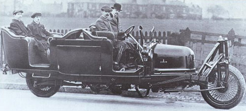
... the first prototype Gyrocar, The Shilovski Gyrocar, was commissioned in 1912 by the Russian Count Pyotr Shilovsky, a lawyer and member of the Russian royal family. It was manufactured to his design by the Wolseley Tool and Motorcar Company in 1914 and demonstrated in London the same year.[3][4] The gyrocar was powered by a modified Wolseley C5 engine of 16–20 hp, with a bore of 90 mm and a stroke of 121 mm. It was mounted ahead of the radiator, driving the rear wheel through a conventional clutch and gear box. A transmission brake was fitted after the gearbox – there were no brakes on the wheels themselves. The weight of the vehicle was 2.75 tons and it had a very large turning radius.
In 1927 Louis Brennan, funded to the tune of £12,000 (plus a £2000 per year) by John Cortauld built a rather more successful gyrocar. Two contra-rotating gyros were housed under the front seats, spun in a horizontal plane at 3500 rpm by 24V electric motors powered from standard car batteries. This was the greatest speed obtainable with the electric motors available, and meant that each rotor had to weigh 200 lb (91 kg) to generate sufficient forces. Precession was in the vertical fore-aft plane. The car had a Morris Oxford engine, engine mountings, and gearbox. Two sidewheels (light aircraft tailwheels were used) were manually lowered on stopping; if the driver forgot and switched off the gyros and walked away, the car would continue to balance itself using the gyro momentum for a few minutes, and then the wheels would automatically be dropped to stop tipping.
Much more detailed information on the Schilovski Gyrocar - including drawings and close-up photographs - can be found at:
http://www.dself.dsl.pipex.com/MUSEUM/TRANSPORT/gyrocars/schilovs.htm
Count Peter Schilovski did indeed survive the Great War and returned to live in south London with his wife and family.
https://timesmachine.nytimes.com/timesmachine/1914/05/17/100316422.pdf
NY Times
https://web.archive.org/web/20060703100019/http://www.dself.dsl.pipex.com/MUSEUM/TRANSPORT/gyrocars/schilovs.htm
THE
SCHILOVSKI GYROCAR.
Two wheels good, four wheels bad.
Two wheels good, four wheels bad.
Research has disclosed a good deal more information on this amazing machine, and at last, some decent pictures. Much information comes from an article by Terence Clements in Meccano Magazine for Oct 1963; a journal much prized by connoisseurs. Many thanks to Henk Schuuring for providing mechanism details. Here it all is.
Further information has come to light in the shape of a book by Schilovski himself called- wait for it- "The Gyroscope: Its Practical Construction and Its Applications". This was published by Spon of London in 1924. On the title page Schilovsky is described as "President of the Gyroscopic Society of Petrograd".
In
1912 the Russian Count Peter P Schilovski, a lawyer and member
of the Russian royal family, visited the Wolseley Tool and
Motorcar Company, and laid before their engineers plans for a
two-wheeled gyroscopically-stabilised car. At that time
Wolseley were a sizable manufacturer producing ordinary cars,
double-decker buses, taxicabs, lorries and even powerboat
engines.
The Wolseley men were clearly impressed, as the job was accepted, and work began immediately, under the supervision of A W Dring, the Chief Experimental Engineer. The chassis took a year to build, which seems impressively fast given the amount of experimentation that must have been needed. The Count was a frequent visitor during this period to the Adderley Park works in Birmingham.
Some milestones in the development of the "G Y car" as it was known within Wolseley can be deduced from company reports:
...
The Gyrocar was powered by a modified Wolseley C5 engine of 16 - 20 hp, with a bore of 90mm and a stroke of 121mm. It was mounted ahead of the radiator, driving the rear wheel through a conventional clutch and gear box. A transmission brake was fitted after the gearbox- there appear to have been no brakes on the wheels themselves. The small size of the engine in the photograph (in an era when specific outputs were low) indicates that the Gyrocar was distinctly underpowered. The weight of the vehicle was 2.75 tons, concentrated on two wheels- not promising for the heavy mud of the Eastern Front. It has also been said that it suffered from a very large turning circle- again not a good thing in a proposed military vehicle.
Above: Plan of the Gyrocar. Note the large amount of space taken up by the gyroscope, and the offset driveshaft to the rear wheel. The seats are not visible on this drawing.
The gyroscope was of 40 inch diameter and 4.5 inch thick at the rim, and spun at between 2000 and 3000 rpm, powered by a 110V 1.25 hp electric motor. This was beneath the gyro on the same spindle for direct drive. The motor was powered from an engine-driven dynamo mounted beside the clutch. The gyro rotor weighed 12 cwt and apparently absorbed 10% of the engine power. A centrifugal governor rang an alarm bell if gyro rpm fell too low, and support sprag wheels on either side were automatically lowered to prevent the car falling over. A rather fragile-looking system of toothed quadrants actuated by two 95 lb pendulums maintained stabilisation; more details below.
Patents were taken out for the Gyrocar:
British Patent No 12,021 (1909)
British Patent No 12,940 (1914)
New provisional specifications in 1923
This report comes from A W Dring:
"On November 27th, 1913, I made an effort to move the car, which was successful, no derangement of the governing gear taking place. We drove the car backwards and forwards for a distance of about six feet many times. During these tests it was noticeable that one could stand on the side of the car and step into the body without any disturbance of balance. We then moved the car partially round a radius to the left, backwards and forwards. Eventually we drove the car the whole length of the works, backwards and forwards, with four passengers.
Then His Excellency decided to take the machine over on to the track, impressing me that we must go very gently. We drove onto the Arden Road, making two stops on the curve, and we had to reverse so that we should not use full lock. I then drove the car steadily up the Arden Road, going as slowly as possible and slipping the clutch in first gear all the time. We took a wide sweep into the Bordesley Green Road, and suddenly, when opposite the Directors' mess room, the vehicle heeled to the near side and dropped on its sprag. It was lifted by eight men, the engine restarted, and the car driven back to the experimental department, but it was supported by outside assistance as His Excellency did not attempt to balance the car in the street."
On April 28, 1914, the first public demonstration took place before a large and interested crowd in Regent's Park, in central London. According to a contemporary newspaper report, could crawl along with people jumping on and off, and still maintain its stability.
At the outbreak of the First World War in 1914, The Count returned to Russia. Wolseley were fully occupied in war work, and the Gyrocar was not uppermost in their minds; it lay abandoned in a corner of the factory.
The Wolseley directors not unaturally assumed that the Count had been a casualty of either the war or the Russian Revolution. Wanting to get it out of the way, but not wishing to dispose of it completely, they hit upon the extraordinary solution of burying it. This is not normally considered an appropriate method for the long-term storage of motor vehicles...
Gyroscopic stabilisation sounds easy. You fix a gyro to the chassis (axis vertical so you can go round corners) and the gyro refuses to tip over. Simple, yes?
No. It's not that straightforward. If you have a spinning gyroscope and you try to rotate its spin axis, the gyroscope will instead try to rotate about an axis at right angles to your force axis; this is precession. So when the gyrocar tilts sideways, the precession torque generated tilts the gyroscope in a fore-and-aft direction- not much use. Hence the need for a mechanism to indirectly create a sideways restoring force.
If I have understood correctly, it works like this. Any tilting displaces the weights. Through a lever system, the appropriate quadrant is raised until it engages with the gears driven by the cross-shaft running across the top of the gyro. This shaft is driven continuously by a worm on the gyro spindle, so when a quadrant engages the gyro is tilted forwards or back. This, by precession, creates a sideways torque that corrects the tilt.
The original caption of the above diagram read: "SIMPLICITY was evidently not the watchword of the inventor of the Gyrocar, as this magnificent drawing of the stabilising mechanism shows. The gyro flywheel in its trunnion mounting is on the right between the two toothed quadrants, and the chain and weight controls are in the centre. Inset are (top, right) the gearing between the gyro cross-shaft and the quadrant pinions, and (bottom, right) a detail view of one of the weights." Given the date, the article was probably prompted by the exhumation of the Gyrocar in 1938. The editor probably wanted something unusual for the Chrstmas number.
Here is Schilovski's own account of how his car performed, taken from his book:
"The car made experimental runs in London in the summer of 1914. But as the eccentricity of the gyroscope was only sufficient for a smooth curve in the direction of spin of the gyroscope, no rounding of sharp curves was possible to the left. This was the only, but very objectionable, defect, and it prevented the development of the system; no remedy was found at that time to enable the car to negotiate sharp curves, either to left or to right with equal ease."
This account tells us that the Gyrocar was basically unworkable without a major redesign of its stabilising system, which is a fact that had not emerged in any of my previous researchs. The meaning of "the eccentricity of the gyroscope" is, I must admit, currently unclear to me. Obviously the actual rotor was not eccentric or it could never have been spun up to 2000 rpm...


https://en.wikipedia.org/wiki/Ford_Gyron
Ford
Gyron
The Ford Gyron was a futuristic two-wheeled gyrocar first shown to the world in 1961 at the Detroit Motor Show as a concept car designed by Syd Mead. One wheel was at the front and the other at the rear like a motorcycle and the car was stabilized by gyroscopes. The two occupants of the vehicle were seated side by side and, when the vehicle was stationary, two small legs appeared from the sides to support it. The vehicle was created for research and marketing purposes, with no intention to put it into production.
Alex Tremulis was the designer and the gyroscopic systems were based on Louis Brennan's theories. The Ford Motor Company of Detroit gave credit for the Gyron to Louis Brennan. Alex Tremulis had started his career with the US Air Force and worked in 1948 at the Wright-Patterson Air Force Base on the concept of Military flying saucers. He then became the chief designer for the ill-fated Tucker automobile before joining Ford, and was also involved with the Tuscan gyroscopic motorcycles and the Gyronaught XU1 gyroscopic car.
The original fiberglass concept was destroyed in the 1962 Ford Rotunda fire. Only the studio model remains today, it was sold at an auction in December 2012 for $40,000.
Ford
Gyron


http://oldconceptcars.com/1930-2004/ford-gyron-concept-car-1961/
Ford
Gyron Concept Car (1961)
A gyroscopically controlled two-wheeled car called the Gyron. The two-wheeled Gyron, however, would shortly afterward consume much of Tremulis’s effort and time. As the Farrells wrote, Tremulis – whose chief and overwhelming concern was for aerodynamics – believed his design for a two-wheeled gyroscopically balanced car would represent the ultimate in automotive aerodynamics. “In short, Tremulis expected the Gyron to be a genuine breakthrough that would influence all future car design.”The earliest Gyron sketches were rendered in 1956, but Tremulis renewed his interest in the Gyron after learning of GM’s 1959 Firebird III concept, which was hailed as the world’s most advanced and most exotic car. Tremulis felt he could do better. At about that time, Tremulis’s superiors at Ford assigned new hire Syd Mead to work with Tremulis on the Gyron, and together they convinced Ford to let them build a full-scale version of the car. Because a gyroscope of sufficient size to keep the full-scale Gyron upright proved far too expensive for the show car, a pair of wheels on outriggers were added to the design to keep the Gyron upright on the show stand (copywriters explained them away as necessary at low speeds and noted they’d retract at higher speeds); however, its front wheel did steer via a console-mounted dial, and an electric motor did propel the fiberglass-bodied show car up to about 5 MPH. The Gyron debuted in 1961 and would be one of Tremulis’s last projects at Ford, though he would continue to pursue the idea of a two-wheeled gyro car long after he left the company. The fire that destroyed Ford’s Rotunda reportedly took the Gyron as well.Daniel Strohl – blog.hemmings.com
https://en.wikipedia.org/wiki/Gyro_monorail
Gyro
monorail
The gyro monorail, gyroscopic monorail, gyro-stabilized monorail, or gyrocar are terms for a single rail land vehicle that uses the gyroscopic action of a spinning wheel to overcome the inherent instability of balancing on top of a single rail.
The monorail is associated with the names Louis Brennan, August Scherl and Pyotr Shilovsky, who each built full-scale working prototypes during the early part of the twentieth century. A version was developed by Ernest F. Swinney, Harry Ferreira and Louis E. Swinney in the USA in 1962.
The gyro monorail was never developed beyond the prototype stage.
The principal advantage of the monorail cited by Shilovsky is the suppression of hunting oscillation, a speed limitation encountered by conventional railways at the time. Also, sharper turns are possible compared to the 7 km radius of turn typical of modern high-speed trains such as the TGV, because the vehicle will bank automatically on bends, like an aircraft,[1] so that no lateral centrifugal acceleration is experienced on board.
A major drawback is that many cars – including passenger and freight cars, not just the locomotive – would require a constantly powered gyroscope to stay upright.
Unlike other means of maintaining balance, such as lateral shifting of the centre of gravity or the use of reaction wheels, the gyroscopic balancing system is statically stable, so that the control system serves only to impart dynamic stability. The active part of the balancing system is therefore more accurately described as a roll damper.
Historical background
Brennan's monorail
Harmsworth Popular Science illustration showing the monorail mechanism, and (inset) Louis Brennan[2]
The image in the leader section depicts the 22 tonne (unladen weight) prototype vehicle developed by Louis Philip Brennan CB.[3] Brennan filed his first monorail patent in 1903.
His first demonstration model was just a 2 ft 6in by 12 inch (762 mm by 300 mm) box containing the balancing system. However, this was sufficient for the Army Council to recommend a sum of £10,000 for the development of a full-size vehicle. This was vetoed by their Financial Department. However, the Army found £2000 from various sources to fund Brennan's work.
Within this budget Brennan produced a larger model, 6 ft (1.83m) long by 1 ft 6in (0.46m) wide, kept in balance by two 5 inch (127 mm) diameter gyroscope rotors. This model is still in existence in the London Science Museum. The track for the vehicle was laid in the grounds of Brennan's house in Gillingham, Kent. It consisted of ordinary gas piping laid on wooden sleepers, with a fifty-foot wire rope bridge, sharp corners and slopes up to one in five. Brennan demonstrated his model in a lecture to the Royal Society in 1907 when it was shown running back and forth "on a taught and slender wire" "under the perfect control of the inventor".[4]
Brennan's reduced scale railway largely vindicated the War Department's initial enthusiasm. However, the election in 1906 of a Liberal government, with policies of financial retrenchment, effectively stopped the funding from the Army. However, the India Office voted an advance of £6000 in 1907 to develop the monorail for the North West Frontier region, and a further £5000 was advanced by the Durbar of Kashmir in 1908. This money was almost spent by January 1909, when the India Office advanced a further £2000.
On 15 October 1909, the railcar ran under its own power for the first time, carrying 32 people around the factory. The vehicle was 40 ft (12.2m) long and 10 ft (3m) wide, and with a 20 hp (15 kW) petrol engine, had a speed of 22 mph (35 km/h). The transmission was electric, with the petrol engine driving a generator, and electric motors located on both bogies. This generator also supplied power to the gyro motors and the air compressor. The balancing system used a pneumatic servo, rather than the friction wheels used in the earlier model.
The gyros were located in the cab, although Brennan planned to re-site them under the floor of the vehicle before displaying the vehicle in public, but the unveiling of Scherl's machine forced him to bring forward the first public demonstration to 10 November 1909. There was insufficient time to re-position the gyros before the monorail's public debut.
The real public debut for Brennan's monorail was the Japan-British Exhibition at the White City, London in 1910. The monorail car carried 50 passengers at a time around a circular track at 20 mph. Passengers included Winston Churchill, who showed considerable enthusiasm. Interest was such that children's clockwork monorail toys, single-wheeled and gyro-stabilised, were produced in England and Germany.[5][6] Although a viable means of transport, the monorail failed to attract further investment. Of the two vehicles built, one was sold as scrap, and the other was used as a park shelter until 1930.
Scherl's car
Just as Brennan completed testing his vehicle, August Scherl, a German publisher and philanthropist, announced a public demonstration of the gyro monorail which he had developed in Germany. The demonstration was to take place on Wednesday 10 November 1909 at the Berlin Zoological Gardens.
Scherl's Monorail Car
Scherl's machine,[7] also a full size vehicle, was somewhat smaller than Brennan's, with a length of only 17 ft (5.2m). It could accommodate four passengers on a pair of transverse bench seats. The gyros were located under the seats, and had vertical axes, while Brennan used a pair of horizontal axis gyros. The servomechanism was hydraulic, and propulsion electric. Strictly speaking, August Scherl merely provided the financial backing. The righting mechanism was invented by Paul Fröhlich, and the car designed by Emil Falcke.
Although well received and performing perfectly during its public demonstrations, the car failed to attract significant financial support, and Scherl wrote off his investment in it.
Shilovsky's work
Following the failure of Brennan and Scherl to attract the necessary investment, the practical development of the gyro-monorail after 1910 continued with the work of Pyotr Shilovsky,[8] a Russian aristocrat residing in London. His balancing system was based on slightly different principles to those of Brennan and Scherl, and permitted the use of a smaller, more slowly spinning gyroscope. After developing a model gyro monorail in 1911, he designed a gyrocar which was built by Wolseley Motors Limited and tested on the streets of London in 1913. Since it used a single gyro, rather than the counter-rotating pair favoured by Brennan and Scherl, it exhibited asymmetry in its behaviour, and became unstable during sharp left hand turns. It attracted interest but no serious funding.
Post-World War I developments
In 1922, the Soviet government began construction of a Shilovsky monorail between Leningrad and Tsarskoe Selo, but funds ran out shortly after the project was begun.
In 1929, at the age of 74, Brennan also developed a gyrocar. This was turned down by a consortium of Austin/Morris/Rover, on the basis that they could sell all the conventional cars they built.
Principles of operation
Basic idea
The vehicle runs on a single conventional rail, so that without the balancing system it would topple over.
Basic principle of operation: rotation about the vertical axis causes movement about the horizontal axis.
A spinning wheel is mounted in a gimbal frame whose axis of rotation (the precession axis) is perpendicular to the spin axis. The assembly is mounted on the vehicle chassis such that, at equilibrium, the spin axis, precession axis and vehicle roll axis are mutually perpendicular.
Forcing the gimbal to rotate causes the wheel to precess resulting in gyroscopic torques about the roll axis, so that the mechanism has the potential to right the vehicle when tilted from the vertical. The wheel shows a tendency to align its spin axis with the axis of rotation (the gimbal axis), and it is this action which rotates the entire vehicle about its roll axis.
Ideally, the mechanism applying control torques to the gimbal ought to be passive (an arrangement of springs, dampers and levers), but the fundamental nature of the problem indicates that this would be impossible. The equilibrium position is with the vehicle upright, so that any disturbance from this position reduces the height of the centre of gravity, lowering the potential energy of the system. Whatever returns the vehicle to equilibrium must be capable of restoring this potential energy, and hence cannot consist of passive elements alone. The system must contain an active servo of some kind.
Disturbed cg height.[clarification needed] (The difference in height shown is exaggerated.) The balancing system must do work against gravity to right the vehicle when disturbed.
Side loads
If constant side forces were resisted by gyroscopic action alone, the gimbal would rotate quickly on to the stops, and the vehicle would topple. In fact, the mechanism causes the vehicle to lean into the disturbance, resisting it with a component of weight, with the gyro near its undeflected position.
Inertial side forces, arising from cornering, cause the vehicle to lean into the corner. A single gyro introduces an asymmetry which will cause the vehicle to lean too far, or not far enough for the net force to remain in the plane of symmetry, so side forces will still be experienced on board.
In order to ensure that the vehicle banks correctly on corners, it is necessary to remove the gyroscopic torque arising from the vehicle rate of turn.
A free gyro keeps its orientation with respect to inertial space, and gyroscopic moments are generated by rotating it about an axis perpendicular to the spin axis. But the control system deflects the gyro with respect to the chassis, and not with respect to the fixed stars. It follows that the pitch and yaw motion of the vehicle with respect to inertial space will introduce additional unwanted, gyroscopic torques. These give rise to unsatisfactory equilibria, but more seriously, cause a loss of static stability when turning in one direction, and an increase in static stability in the opposite direction. Shilovsky encountered this problem with his road vehicle, which consequently could not make sharp left hand turns.
Brennan and Scherl were aware of this problem, and implemented their balancing systems with pairs of counter rotating gyros, precessing in opposite directions. With this arrangement, all motion of the vehicle with respect to inertial space causes equal and opposite torques on the two gyros, and are consequently cancelled out. With the double gyro system, the instability on bends is eliminated and the vehicle will bank to the correct angle, so that no net side force is experienced on board. When cornering, the counter-rotating gyros avoid instability on corners.
Shilovsky claimed to have difficulty ensuring stability with double-gyro systems, although the reason why this should be so is not clear. His solution was to vary the control loop parameters with turn rate, to maintain similar response in turns of either direction.
Offset loads similarly cause the vehicle to lean until the centre of gravity lies above the support point. Side winds cause the vehicle to tilt into them, to resist them with a component of weight. These contact forces are likely to cause more discomfort than cornering forces, because they will result in net side forces being experienced on board.
The contact side forces result in a gimbal deflection bias in a Shilovsky loop. This may be used as an input to a slower loop to shift the centre of gravity laterally, so that the vehicle remains upright in the presence of sustained non-inertial forces. This combination of gyro and lateral cg shift is the subject of a 1962 patent. A vehicle using a gyro/lateral payload shift was built by Ernest F. Swinney, Harry Ferreira and Louis E. Swinney in the USA in 1962. This system is called the Gyro-Dynamics monorail.
The advantages of the monorail over conventional railways were summarised by Shilovsky. The following have been claimed.
Reduced right-of-way problem
The close association of the vehicle with its single rail, its inherent ability to bank on bends, and the reduced reliance on adhesion forces are all factors which are pertinent to the development of surface travel. In principle, steeper gradients and sharper corners may be negotiated compared with a conventional adhesion railway. Typical high speed train designs have radius of turn of 7 km, with consequently few options for new routes within developed countries, where almost all of the land is under individual or corporate ownership.
In his book, Shilovsky describes a form of on-track braking, which is feasible with a monorail, but would upset the directional stability of a conventional rail vehicle. This has the potential of much shorter stopping distances compared with conventional wheel on steel, with a corresponding reduction in safe separation between trains. The result is potentially higher occupancy of the track, and higher capacity.
Reduced total system cost
While the individual vehicles are likely to be expensive, the greatest cost arises from the construction and maintenance of the permanent way, which, for a single rail at ground level must be cheaper.
Benign failure modes
The angular momentum in the gyros is so high that loss of power will not present a hazard for a good half-hour in a well designed system.
Reduced weight
Shilovsky claimed his designs were actually lighter than the equivalent duo-rail vehicles. The gyro mass, according to Brennan, accounts for 3–5% of the vehicle weight, which is comparable to the bogie weight saved in using a single track design.
Potential for high speed
High speed conventionally requires straight track, introducing a right of way problem in developed countries. Wheel profiles which permit sharp cornering tend to encounter the classical hunting oscillation at low speeds. Running on a single rail is an effective means to suppress hunting.
Turning corners -- Contribution of body rotation
Considering a vehicle negotiating a horizontal curve, the most serious problems arise if the gyro axis is vertical. There is a component of turn rate Ω {\displaystyle \Omega } \Omega acting about the gimbal pivot, so that an additional gyroscopic moment is introduced into the roll equation...
The balancing loop will become unstable. However, an identical gyro spinning in the opposite sense will cancel the roll torque which is causing the instability, and if it is forced to precess in the opposite direction to the first gyro will produce a control torque in the same direction.
In 1972, the Canadian Government's Division of Mechanical Engineering rejected a monorail proposal largely on the basis of this problem. Their analysis [9] was correct, but restricted in scope to single vertical axis gyro systems, and not universal.
Maximum spin rate
Gas turbine engines are designed with peripheral speeds as high as 400 m/s,[10] and have operated reliably on thousands of aircraft over the past 50 years. Hence, an estimate of the gyro mass for a 10 tonne vehicle, with cg height at 2m, assuming a peripheral speed of half what is used in jet engine design, is a mere 140 kg. Brennan's recommendation of 3–5% of the vehicle mass was therefore highly conservative.
https://www.facebook.com/UNILADTech/videos/gyroscope-stabilized-3d-printed-rc-car/528157111264999/
https://www.youtube.com/watch?v=Rlnexcft2ns&feature=emb_logo
Gyro
Stabilized 3D Printed RC Car
One of my most requested project has been to 3D print a radio controlled car. I decided to modify that request and build a 2 wheeled car stabilized by a rotating gyroscope. There was a car called the Gyro-X in the 1960s that inspired this entire project. The main idea is to have a vehicle balancing on 2 wheels and staying upright by the use of a heavy rotating wheel called a gyroscope. I designed everything in Fusion360 and 3D printed all the parts on the new Creality CR-10 Max. By using a quite powerful brushless electric motor with a belt system it move along nicely. Even though the steering didn't work I would still call it semi-successful.
https://www.thingiverse.com/thing:3442
http://www.youtube.com/watch?v=Ov5WVhhIdWo
3D
Printed Motorized Gyro
https://www.youtube.com/watch?v=ANUWBNLoN28
Gyroscopic
Stabilization of a Robotic Bicycle
A Control Moment Gyroscope (CMG) is used to balance or stabilize an unmanned autonomous bicycle.
Q: Im doing a similar project but i want to install the gyro on the front wheel, what suggestions do you have regarding powering the gyro
A: I would choose a brushless DC motor (hobby is fine) that is rated to supply a continuous torque that's at least a few times greater than the inertia of the flywheel you're using (1/2mr^2 if its a disk shaped flywheel) and has a no load speed rated around 25,000 rpm assuming you will be powering the flywheel at 15,000 to 20,000 rpm. This is just a general approach but you should determine how fast you want your flywheel to accelerate (from rest because this is the most demanding task) and then solve for the required continuous torque using (torque = J*accel) where J is flywheel's inertia and accel is the desired acceleration you want. Feel free to read through my thesis :
http://kb.osu.edu/dspace/handle/1811/59568
Control
Moment Gyroscope Stabilization and Maneuverability of
Inherently Unstable Vehicles and Mobile Robots
Abstract:
The control problem of stabilizing an inherently unstable body, such as the inverted pendulum, is a classic control theory problem. Traditionally, the solution to this problem has been approached through methods of dynamic stabilization where the inverted pendulum is placed on a wheeled cart that can travel with one translational degree of freedom. This cart essentially accelerates the pivot of the inverted pendulum to accelerate the pendulum to induce a rotation that counteracts the imbalance in the system. A different approach to stabilizing a static or stationary inverted pendulum makes use of the intriguing phenomena known as gyroscopic precession. Precession and the physics of gyros are governed by conservation of angular momentum. By utilizing this technology in a novel way, groundbreaking progress can be made in the field of autonomous stability of inherently unstable mobile robots and vehicles (e.g. two wheeled vehicles). Gyroscopic effects can be found today in simple devices such as a spinning top or a bicycle’s wheel in motion. Gyros are also found in very complex mechanisms such as those used for satellite attitude and large ship anti-roll systems. Recent gyro studies have shown tremendous promise for providing unparalleled capabilities in stabilization and maneuverability for both on and off-road vehicle applications.
https://ieeexplore.ieee.org/document/6859392?tp=&arnumber=6859392&url=http:%2F%2Fieeexplore.ieee.org%2Fiel7%2F6849600%2F6858556%2F06859392.pdf%3Farnumber%3D6859392
Gyroscopic
stabilization of an unmanned bicycle
Simon Kalouche, et al.
Abstract:Simon Kalouche, et al.
There are two theoretical methods by which a two wheeled vehicle oriented in tandem can be stabilized: dynamic stabilization and control moment gyroscope (CMG) stabilization. Dynamic stabilization utilizes tactical steering techniques to trigger a lean in the vehicle in the intended direction for balancing, while CMG stabilization employs the reactive precession torque of a high speed flywheel about an axis that will act to balance the vehicle. Of these two, CMG stabilization offers greater advantages for static vehicles. This paper proposes a first order sliding mode controller (SMC) design to control the CMG and stabilize a bicycle at zero-forward velocity. This study also compares the SMC method to a PID controller to validate the advantages of the SMC controller for the highly non-linear system dynamics of static stabilization. The result of two experimental setups are presented and discussed. The first experimental platform is a single degree of freedom (DOF) inverted pendulum and the second is a three DOF bicycle.
http://craziestgadgets.com/2008/04/29/uno-the-gyro-balanced-motorcycle/
Uno
the Gyro Balanced Motorcycle
On the top one list of things you will never catch me riding, the Uno is numero uno on the list. The Uno is a combination motorcycle and segway. It actually has two wheels, they are side by side. The Uno balances via a gyroscope, much like a segway does. To turn the Uno, you lean into the the turn, the wheels themselves are fixed and don’t rotate. Scary stuff or transportation of the future?

https://www.bikesales.com.au/editorial/details/5-self-balancing-motorcycles-105635/
5 self-balancing motorcycles
The use of
gyroscopes is the next bike thing in motorcycle safety,
especially aiding the very new and very old riders among our
ranks. Here are five of the best self-balancing bikeshttps://ultimatemotorcycling.com/2016/12/01/thrustcycle-unveils-gyrocycle-a-self-balancing-motorcycle/
Thrustcycle
Unveils GyroCycle, a Self-Balancing Motorcycle
...The GyroCycle an energy efficient vehicle with rock solid stability,” says Thrustcycle Enterprises LLC President Clyde Igarashi. “The gyroscope functions as both a stabilizer and mechanical battery so you get the benefits of both.”
For self stability, the GyroCycle utilizes internal flywheels, which create a gyroscopic effect that ensures the bike will remain upright and stable both during riding and while at a standstill (when powered up).
Thrustcycle says because the GyroCycle’s system maintains a fixed plane in space, the vehicle will be less likely to lose traction when going into turns because the gyroscope will maintain lateral integrity. “The self-balancing function gives the rider more control and greatly increases safety,” Thrustcycle says.
Besides reusing energy stored in the flywheel for the self-balancing motorcycle function, the GyroCycle also utilizes a mechanical battery that reuses energy normally lost during braking. This energy is absorbed back into the flywheel and is later used for accelerating....
http://thrustcycle.com/index.html
About the Thrustcycle Team:
Co-founder Clyde Igarashi, who holds an MBA in finance from New York University, first met co-founder and engineer David Ryker nine years ago while working on an energy storage project. Both were interested in green technology and building cleaner, more energy-efficient vehicles....
US2015143932
GYROSCOPIC SYSTEMS TO STABILIZE VEHICLES AND RECYCLE KINETIC ENERGY
AbstractGYROSCOPIC SYSTEMS TO STABILIZE VEHICLES AND RECYCLE KINETIC ENERGY
Gyroscopic systems to stabilize vehicles and provide kinetic energy recovery are disclosed. The gyroscopic system uses gyroscopic forces to maintain a vertical orientation at zero and low speeds, as well as maintain stability at all speeds. The gyroscopic forces are also be used to affect the bank angle of vehicles in turns, and to improve cornering by shifting forces to the inside wheels. The gyroscopes are also used to store kinetic energy, which is later used to accelerate the vehicle.
https://www.instructables.com/id/Self-Balancing-Scooter-Ver-10/
Self
Balancing Scooter Ver 1.0
https://www.youtube.com/watch?time_continue=2&v=IaLiheNz9a8&feature=emb_logo
Scitech
Workshop Prototype: Self-balancing scooter v1.0
https://www.youtube.com/watch?v=L7mny2q622E
Scitech
Workshop Prototype: Self-Balancing Scooter v2.0
http://cobbsblog.com/gyro/tuscantext.html
Thomas
SUMMERS, Jr
Gyro-X
Update
Including Details of the Tuscan Gyro-Stabilized, Half-Track, Trail Bike
Including Details of the Tuscan Gyro-Stabilized, Half-Track, Trail Bike
Several people have written to me in recent months about the Gyro-X project, adding their knowledge and observations, for which I am very grateful. I have edited their comments for presentation purposes, so that they can be shared with others who are interested in this subject. -- Stephen Cobb
Tuscan -- Gyro-Stabilized, Half-Track, Trail Bike
We learned about this fascinating off-shoot of the Gyro-X project from Richard R Fuller of Jacksonville, Florida. Richard's father was one of the founding associates with Gyro Transport Systems (GTS). His name was Richard H. Fuller and he was the purchasing analyst for them. The younger Richard Fuller contacted us while searching the web for material on GTS which until very recently he thought was called Tuscan something. He was only 14 when the company started in Salt Lake City, Utah. He reports that within two years the company was disolved, ending hopes of moving to Ponce, Puerto Rico to build the manufacturing plant.
However, during that time, when the company was located in Northridge, he met Alex Tremulys, Tom Summers, Al Crane, and Ed Davis. When the company dissolved, Richard's father was offered a job at American Airlines and the family moved to Tulsa. But the younger Richard kept a lot of materials, including an 8x10 glossy of the Gyronaut X-1 signed by Alex Tremulus to his father, and the product brochure for the Tuscan. Richard kindly scanned the brochure for display on the web.
The Hellfire Connection
A considerable amount of very useful background information was supplied to me by Jerry Goldstein, who also filled in some details of the Gyro Hawk kit car. Here's what Jerry told me:
"What happened to the Gyro-X was relayed to me by Tom Summers when I tracked him down in 1991, after realizing the need for a small, enclosed and stabilized motorcycle. An old timer had seen the Science & Mechanics article and I researched it. I found Alex Tremulus just before he passed away and through his wife was able to get in touch with Tom Summers. I visited Tom and we talked about the article.
"Tom had his own gyroscope company in the fifties, and contracted with the US Forest service to build several prototype mechanical mules for carrying ore from copper mines located on US forest preserves that were remote and inaccessible except by pack mules. The idea was to build a mono-trak vehicle that could access the mine through the wilderness without having to build roads through the prime forest. Tom developed several testbeds, generating considerable interest and attracting Alex Tremulus and a group of investors from the University of Utah who wanted to build a prototype passenger car using Toms designs.
"An investment group was formed and a prototype built. The car was built in Los Angeles. The body design is by Alex Tremulus who also styled the Ford Thunderbird and the Ford Gyron (note: we plan to add more about the 2-wheeled Gyron soon).
"The car prototype actually used the powerplant from one of the ore mules which belonged to the US government. Tom maintains that the investment group attempted to steal his patented designs and go ahead on the project without compensating him. He sued the group and effectively killed the project, but it left him ruined financially.
"He was retired from Tally Corporation in 1988 when it was acquired by Hughes after old man Tally died. The new owners found Tom " wandering the halls" and put him out to pasture, not realizing he was the foremost inertial guidance engineer of the post WWII era. Toms design of the Hellfire missile guidance system is still in use today. Tom tried unsuccessfully to bring the gyrocar to reality several times over the period from 1968 until his patents expired some twenty odd years later."
Jerry feels that Tom is something of a national treasure, and an unsung hero. "He invented the vertical sensing device that became the key to the success of the Norton bombsite in WWII. The Germans tried to entice him into sharing his information with them but the U.S. Gov't put Tom to better use here. Tom had his own gyroscope company in the '50s and was a pioneer in the field of inertial guidance. He held over 100 patents. Tom worked for Tally corporation in the '70s, perfecting the guidance system of the Hellfire missile for which Tally was a prime contractor. His effort to produce the gyro vehicle began with the ore carrying "mules" that provided the powerplant and gyro for the car that appeared in Science and Mechanic in 1968."
http://cobbsblog.com/gyro/tuscan.html
Tuscan
-- Gyro-Stabilized, Half-Track, Trail Bike

The cover of the original product brochure.
Several readers of this page have suggested that the Tuscan was not in fact gyro-stabiized. After considerable reflection I agree that it is unlikely the model pictured here used a gyro. However, we are told in the Science and Mechanics Gyro-X article that Gyro Transport Systems was working on a gyro-stabilied trail bike for the US Forest Service and I'm speculating that it was a modified version of the Tuscan. As always, I am happy to hear from anyone who can shed light on these machines. Email me as webbloke at cobb dot com or leave a comment at the gryocar blog.
https://worldwide.espacenet.com/advancedSearch?locale=en_EP
Thomas
Summers, Jr. Patents ( Gyro-Stabilized Vehicles )
US3373832 : Gyro
vehicleUS3410357 : Gyro stabilized vehicle
https://www.usatoday.com/story/money/2016/10/11/bmws-future-vision-includes-self-balancing-motorcycle/91908774/
Oct. 12, 2016
This
BMW motorcycle balances itself
BMW Motorrad Vision
BMW Motorrad Vision

https://en.wikipedia.org/wiki/Lit_Motors
Lit
Motors

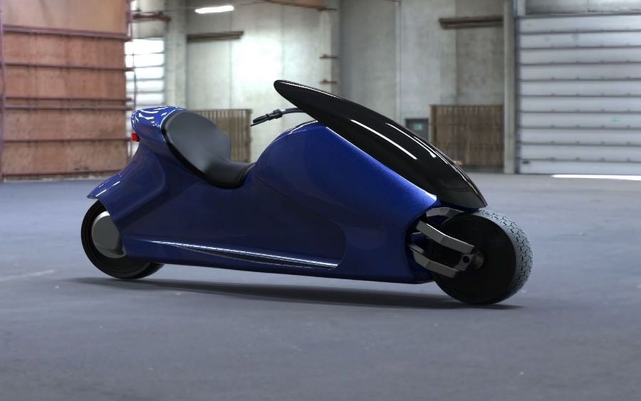
Lit Motors Inc. is a San Francisco-based company that designed conceptual two-wheeled vehicles, including a fully electric, gyroscopically stabilized vehicle.[1]
Founded by Daniel K. Kim in 2010, Lit Motors designed concepts for two-wheeled vehicles with a focus on innovative technologies. They have released information about two projects: the AEV (auto-balancing electric vehicle) often referred to as the "C-1" and the Kubo cargo scooter. The inspiration for Lit Motors came to Kim in 2003, when he was nearly crushed by a chassis while manually assembling a bio-diesel Land Rover Defender 90.[2] Kim decided to "chop a car in half" to create what is now the C-1
https://en.wikipedia.org/wiki/Control_moment_gyroscope#Single-gimbal
Single-gimbal -- The most effective CMGs include only a single gimbal. When the gimbal of such a CMG rotates, the change in direction of the rotor's angular momentum represents a torque that reacts onto the body to which the CMG is mounted, e.g. a spacecraft. Except for effects due to the motion of the spacecraft, this torque is due to a constraint, so it does no mechanical work (i.e., requires no energy). Single-gimbal CMGs exchange angular momentum in a way that requires very little power, with the result that they can apply very large torques for minimal electrical input...
https://www.wired.com/2012/05/lit-motors-c1/
Exclusive:
This Is the Gyro-Stabilized, Two-Wheeled Future of
Transportation
...In its current form, the two gyros each put out 266 pound-feet of torque as they spin, keeping the C1 upright no matter the speed or angle. In final production form, the combined force of the pair of gyros will max out at around 1,300 pound-feet, enough to keep the C1 vertical while stopped, at steady-state cruising and planted to the road at a maximum lean angle of 45 degrees.
The ability to simply pull the entire gyro setup from the chassis is a design decision that will make it to production, allowing the C1 to be serviced quickly and efficiently, much like the battery pack mounted to the floor of the Tesla Model S. It also helps when something goes awry during its maiden voyage in the eager hands of someone outside the Lit Motors studio...
https://worldwide.espacenet.com/advancedSearch?locale=en_EP
An augmented traction system for a two-wheeled vehicle comprising a CMG (control moment gyroscope) system including a plurality of CMGs to provide a first torque vector to decrease a roll angle of a turn of the vehicle and to increase force on one or more of the tires of the vehicle on a road surface, a steering system for the vehicle, the steering system to determine a steering control for the turn of the vehicle at a particular vehicle speed and roll angle, based on sensor data, and an aerodynamic control system to actuate one or more aerodynamic elements of the vehicle, the one or more aerodynamic elements to provide a second torque vector to decrease the roll angle of the vehicle.

PROBLEM TO BE SOLVED: To provide a vehicle stabilization system.SOLUTION: In an embodiment of the invention, a vehicle stabilization control unit can determine a control moment value for one or more gyroscopes coupled to a vehicle frame to exert for stabilization of the vehicle frame. The number of input axes for the flywheels of the one or more gyroscopes to precess is preferably increased in order to generate the determined control moment value. In some embodiments, the one or more gyroscopes are further coupled to a turntable, and increasing the number of input axes for the flywheels comprises rotating the turntable. Furthermore, in some embodiments, the one or more gyroscopes comprise at least two gyroscopes coupled inline to the vehicle frame (e.g., aligned lengthwise with respect to the front and rear wheel to spin and precess in opposite directions with respect to each other).

Embodiments of the invention describe receiving, via a plurality of sensors, data indicating vehicle information. Said information may indicate at least orientation of a frame of a vehicle, orientation of a front wheel of the vehicle with respect to the frame, orientation and rotational speed of a first and second flywheel, and speed of the vehicle. In one embodiment, each flywheel is included in a first and second gyroscope coupled to the vehicle frame. Based, at least in part, on the data received from the plurality of sensors, at least one of the orientation and rotational speed of at least one of the flywheels may be adjusted. Said adjustment may further be based on an input to change at least one of speed and direction of the vehicle.
In embodiments of the invention, a vehicle stabilization control unit may determine a control moment value for one or more gyroscopes coupled to a vehicle frame to exert for stabilization of the vehicle frame. A number of input axes for the flywheels of the one or more gyroscopes to precess may be increased in order to generate the determined control moment value. In some embodiments, the one or more gyroscopes are further coupled to a turntable, and increasing the number of input axes for the flywheels comprises rotating the turntable. Furthermore, in some embodiments, the one or more gyroscopes comprise at least two gyroscopes coupled inline to the vehicle frame (e.g., aligned lengthwise with respect to the front and rear wheel to spin and precess in opposite directions with respect to each other).
Related patents:
Gyro stabilized remote controlled toy motorcycle having good stability and control without using ground contacting auxiliary wheels or the like. The motorcycle comprises a chassis supporting a fixed angle rear wheel drive and associated motor and a castered front wheel. A gyro wheel having an axis nominally parallel to the axis of the rear wheel is mounted in a gimbal with a vertical axis in the forward part of the chassis and connected to the front wheel fork and post to turn the front wheel responsive to the rotation of the gimbal relative to the chassis. The chassis further includes a radio receiver, battery power and a steering device, such as a motor and slip clutch for torquing the gyro wheel gimbal. To turn in a first direction the gyro gimbal is torqued in the opposite direction, initially causing the front wheel to also turn in the opposite direction. As the motorcycle and the gyro lean into the turn, a correcting torque is generated by the gyro and caster of the front wheel, overcoming the initial steering torque to maintain the proper steering angle and balance for the motorcycle. Various embodiments are disclosed.

The invention relates to the field of vehicle engineering, and more particularly to gyro-stabilized two-wheeled vehicles, primarily motorcycles. Essence of the invention: a gyro-stabilizer for a two-wheeled single-track vehicle, preferably a motorcycle, is configured in the form of a gyroscope in a gimbal mount, an outer ring of which is connected by a two-way axial pivot joint to the frame of a vehicle, wherein the axis of said joint is oriented along the longitudinal axis of the vehicle; an inner ring of the gimbal mount is connected by a two-way axial pivot joint to the outer ring; and a spin axis of the gyroscope is connected by a two-way axial pivot joint to the inner ring of the gimbal mount, wherein the axes of all three pivot joints are mutually perpendicular, and wherein the gyro-stabilizer has a means for locking rotation of the outer ring about the axis of the pivot joint between said outer ring and the frame of the vehicle. According to the invention, the gyro-stabilizer is disposed on the swingarm of the rear wheel and has a means for locking rotation of the inner ring about the axis of the pivot joint between said inner ring and the outer ring, wherein each locking means is in the form of a servomotor which allows the forced rotation of the corresponding ring in response to a command from a microcontroller controlling at least the speed and the permissible bank angles of the vehicle, and an additional weight is secured on the axis of the pivot joint between the inner ring and the spin axis.

A self-balancing enclosed motorcycle includes a platform base, a seat, a first wheel and a second wheel, a rear cabin, a door component and a gyroscope system. The gyroscope system includes a housing, a gyroscope sensor, a calculation device, an electrical coding device, a microprocessor, a servomotor, a vertical corrective rod movably extended from the servomotor, a first balancing assembly and a second balancing assembly. The first balancing assembly is mounted in the housing to engage with the vertical corrective rod. The second balancing assembly mounted in the housing at an opposite side of the first balancing assembly to engage with the vertical corrective rod. The vertical corrective rod is normally retained in a substantially vertical orientation with respect to the platform base.

The invention discloses a self-balancing electric motorcycle. The self-balancing electric motorcycle comprises a seat frame, pedal plates, a battery, a motorcycle frame housing and a hub fixed to the inner part of the motorcycle frame housing; a plurality of silicon sheets are mounted on the inner circle of the hub; a wheel is mounted on the outer circle of the hub; a motor stator and a transmission ring are mounted in the hub; the transmission ring comprises an outer ring and an inner ring which rotates in the outer ring; the outer ring is connected with the motor stator; the hub is connected with a hub cap to drive the inner ring. According to the self-balancing electric motorcycle provided by the invention, under the action of a gyroscope and a controller, self-balancing adjustment can be realized; meanwhile, through the optimization of a motor driven system, tiny gaps are reserved between the motor stator and the silicon sheets, and the silicon sheets are embedded inside the hub, so that the hub generates a forward driving force, and travelling is realized through the cooperation of the hub cap and the transmission ring.
The utility model provides a stability adjustable type built-in gyroscope of a motorcycle. The gyroscope comprises a horizontally arranged ring and a center shaft connected with the ring, wherein the center shaft vertically penetrates through the circle center of the ring, a bearing is arranged on the bottom of the ring, the ring is connected with the center shaft through the bearing, a balance weight ring is arranged on the outer side of the ring, three S/N polepieces are arranged on the inner side of the ring, a Hall sensor is arranged the lower end of each polepiece, a coil is arranged on the center shaft, the coil and the polepieces are located at the same height, a controller is arranged at the upper end of the center shaft, and a control chip is arranged in the controller in an integrated mode and controls the reversing of an alternating current motor in the electronic way so as to obtain the characters of a direct current motor and avoid the defects of the mechanism of the direct current motor. According to the gyroscope, the rotating speed of the gyroscope can be adjusted through the control chip so that the stability of the gyroscope can be controlled and selected when the motorcycle travels in different environments, and stability under the same rotating speed is improved too.

The device includes, interposed between the handlebar (2) and the fork of the front wheel (4), a first set of members (2,6,8,10,36,12,14,16,18) for inducing, as a result of a solicitation of the handlebar in the direction of the arrow (arrow 1), towards the interior of the turn, a pivoting (arrow 3) towards the exterior of the turn called a counter-turn, of the front wheel around a pivot axis (20) of the fork. There is a second set of members (24,30,22,8,20,36,12,14,16,18) whose activation is dependent on the information of a gyroscope (24), to induce the motorcycle to lean towards the interior of the turn while the motorcycle encounters the turn. There is a third set of members (26,28,32) whose activation is dependent upon the speedometer (26) for adjusting the extent of the turning or counter-turning of the front wheel around the pivot axis (20) of the fork, as a function of the speed. Thus, the movement of the handlebar in the direction of the interior of the turn, induces a counter-turn followed by an automatic turning of the motorcycle, whose factors of execution varies as a function of the speed of the latter.

A wholly-closed automatic self-balancing two-wheeled motorcycle is characterized in that: the utility model consists of a motorcycle vehicle body (1), a vehicle body balance measuring device (2) and a motorcycle condition regulating device (3), wherein, the vehicle body balance measuring device (2) is a gyroscope; the motorcycle condition regulating device (3) is directly connected with the vehicle body balance measuring device (2). The utility model solves the problem of poor balance performance, greater operation difficulty, less comfort and backing inability of traditional two-wheeled motorcycle; meanwhile, compared with ordinary four-wheeled vehicle, the utility model has the advantages of energy saving, high speed and agility (being able to easily reach a high speed that is difficult for four-wheeled vehicle under equal oil consumption condition), small space usage, simple operation and novel structure.
A fully enclosed automatic self-balancing motorcycle is composed of a motorcycle body, a motorcycle balance measurer (gyroscope) and a motorcycle posture regulator controlled by said gyroscope. Its advantages are high balance performance, high speed, and able to run back.

The utility model relates to a gyroscope two-wheel toy motorcycle which uses the inertia principle of a gyroscope. The gyroscope which uses a motor as power is fixed on a motorcycle handle to automatically control balance; the utility model is also provided with a balanced pendulum hammer, the balanced pendulum hammer can be disengaged from a balance position under the operation of remote control or line control, which enables the motorcycle to temporarily lose balance, and the gyroscope is forced to wrench the motorcycle handle by the inertia to play the function of controlling turning. The gyroscope two-wheel toy motorcycle runs by completely using two wheels, and the running route can be freely controlled.
