Hemp
Plastic
Related : HAUSER : Alsi-Paper ( Bentonite - Cellulose ) / LEUNG : Cellulose NanoCrystals ( Stronger than carbon fiber or Kevlar ).
Martin
ERNEGG : Zeoform
http://www.zeoform.comZEOFORM
Recycled
Waste Cellulose Fiber ( especially Hemp ), processed
into eco-friendly artificial hardwood, comprising
fibres having a length weighted average fibre length
(“LWAFL”) of 0.25 to 0.40 mm.
Introduction
ZEO is a privately held, Australian-based company that has developed and patented a revolutionary eco-friendly industrial material, derived from raw cellulose – the most abundant source of fibre on the planet.
Pure cellulose extracted from recycled and reclaimed papers, industrial hemp, discarded natural fabrics, waste and renewable plants, is sustainably transformed into a strong, durable, flexible base material called ZEOFORM™.
Similar in look, feel and function to a dense hardwood, ZEOFORM can be sprayed, moulded or formed into infinite shapes, sizes, colours and variations – including specialised substrates for unique applications in any industry requiring woods, plastics and resins for manufacturing.
ZEOFORM is truly 100% eco-friendly – with no glues, binders, chemicals or additives of any kind. A unique patented process produces a beautiful, versatile, extremely strong material for thousands of products used every day, worldwide.
While rapidly diminishing resources of wood, and environmentally damaging petrochemical derivatives are untenable as source materials into the future, ZEOFORM converts waste into a UNIVERSAL Material that will replace most plastics, woods and composite materials used in manufacturing today.
ZEOFORM has been called ‘The Holy Grail of eco-materials‘, as its universal application is limited only by our imagination. Guided by sustainable business principles, and dedicated to positive planetary change, the global directive of ZEOFORM is – ‘Making Form Sustainable‘.
Zeoform is a revolutionary material that changes everything. Made from cellulose fibres and water – and absolutely nothing else, our patented process converts cellulose fibres into an industrial strength moulding material capable of being formed into an unlimited array of products. Zeoform is 100% non-toxic, biodegradable, compostable and ‘locks up’ carbon into beautiful, functional forms. A perfect solution for emerging hemp industries and bio-waste nations!
Zeoform at a Glance
An Australian-based company launching a new global industry.
An industrial strength moulding material made of cellulose fibres and water.
Made from cellulose by-products including hemp, agricultural bio-mass, recycled or discarded (de-inked) paper, cotton, rice, jute, cane, wood, bamboo and any other clean cellulose feedstock.
Produces commercial / industrial grade material ranging from styrofoam-light to ebony-dense.
Can be combined with dyes, minerals, substrates, sand, cement, carbon, kevlar and other elements to enhance colour, strength, flex, resilience, conductivity, waterproofing and other qualities.
An exciting new material for architects, engineers, designers, builders, manufacturers & makers.
Offers a sustainable solution for farmers, growers, waste managers, paper mills etc.
Will revive declining industries (eg paper mills), offer mass employment, generate new economies.
Will help make the world a better place!
Hemp Comparison
Several grades of Zeoform have been extensively tested to international standards (ISO) by qualified 3rd parties – a European University, as well as a special (European) Government programme to research and qualify emerging renewable construction materials.
In addition to the information below, we intend to release further technical data pertaining to specific comparisons and testing, including UV resilience, waterproofing with natural materials, compostability, and other relevant factors.
Zeoform can provide a quote for bespoke testing and qualification for your specific applications upon request.

US6379594
Process
for producing workpieces and molded pieces out of
cellulose and/or cellulose-containing fiber material
Inventor(s): DOEPFNER HORST; ERNEGG MARTIN ; BRAMSTEIDL ROBERT
Applicant(s): ZELLFORM GES M B H [AT]
Also published as: WO9811973 / ATA162796 / AT405847 / ES2236802
A process for producing a work piece includes providing raw material which is cellulose-containing and fibrous, which is not any part of a tree, and which is selected from the group consisting of, crude plant fibers, pure cellulose, waste paper, and waste cardboard; adding water to the raw material; finely chopping the raw material in a machine by continuously grinding the raw material with a total energy expenditure of at least 0.5 kWh/kg, based on dry weight of the raw material, into a microfiber pulp having an increased internal fiber surface and an increased degree of interlinking; forming the microfiber pulp to provide a shaped green body; and drying the shaped green body by removing water therefrom to harden the shaped green body and form a work piece, wherein the shaped green body is hardened into the work piece by drying only without admixture of bonding agents to the microfiber pulp and without use of external pressure, and wherein the work piece has characteristics which depend on degree of grinding to produce the microfiber pulp and which range from (a) paper carton-like to (b) wood-like to (c) horn-like, the work piece having a specific gravity which ranges up to that of pure cellulose, 1.5.
BACKGROUND OF THE INVENTION
1. Field of the Invention
The invention concerns a process for producing blanks or molded bodies with similar characteristics as wood from one or more cellulose-containing, fibrous raw material, e.g. pure cellulose, but also crude fibers or the complete plant or other constituents of hemp, flax, reed, cotton, straw, etc., as well as old cardboard and waste paper, through specific processing of said fibers to form a microfiber pulp which is then dried, if necessary after first draining and forming it, as well as the diverse use of said microfiber pulp as bonding or matrix material for taking up filler materials.
The objective is an economical production of the aforementioned materials, bodies and molded parts having good technical properties, if possible based on ecological criteria.
2. Description of the Related Art
In the patents CH 254243, DE 4207233 A1, EP 402866 A2, U.S. Pat. No. 3,935,924 A, as well as GB 2066145 A, it is suggested using beaten cellulose or microcellulose pulp as bonding agent, filter, speaker membrane or as thickening and reinforcing agent for paper products. These patents appear to oppose individual claims of the patent under consideration. The process suggested in the CH 254243, however, requires extremely long, uneconomical processing times and the resulting, gelatinous slime has a consistency that makes the drainage of water very difficult. In addition, higher densities and strength can be obtained with this process only by using pressure (at least 4 kg/cm<2>) and heat (above 100[deg.] C.).
Basically, considerably lower strengths are achieved on the basis of this Swiss patent and other already known processes than with our process.
Thus, according to the DE 4207233 A1, waste paper is beaten and stirred and, following the introduction of air, is dried to filtering bodies with low strength. It is significant that the inventor considers it necessary to admix the fiber pulp with calcium oxide powder, as is mentioned several times in this patent, in order to obtain firmness and stability for the filter block through a post-curing. The introduction of air into the fiber pulp thus refers to an obviously hardly processed base material with extremely low bonding properties.
The word "microcellulose" by itself generally does not define either the degree of shortening, squeezing, fibril removal, hydration or the adjusted fractional composition of the fibers, which are critical for the internal cross-linkage, matting and bonding properties.
It is significant that the EP 402866 A2 also does not address the fineness via these bonding properties, but via the filtering characteristics of the material, that is to say whether the material is adjusted finely enough to prevent certain particles (e.g. bacteria and the like) from passing through the filter.
The fact that the use of polymers as raw material is also suggested for these filters, in the cited examples as well as the claims, serves as further proof that the refinement function has another purpose as well as has a very different qualitative and quantitative cause. Thus, the processing clearly does not serve to increase the hydrogen bonding between fibers.
The U.S. Pat. No. 3,935,924 A appears to deal only with carbon-fiber reinforced fine paper with somewhat increased bonding properties for speaker membrane production.
All the aforementioned patents use only pure cellulose, but not cheap crude fibers or other plant constituents. Refiners are used only for shortening of cellulose fibers to make these suitable for further processing, e.g. in a "high pressure homogenizer." This high-pressure pulping in an expansion nozzle results in totally different fractional compositions and defibration degrees. The same is true for the GB 2066145 A. The pulp produced with this process has considerably lower bonding properties. It is significant that the suggestion is only for using this pulp as reinforcement for paper, but not for the bonding of wood replacement products such as furniture panels or, following the drying, as synthetic material replacement. Adding approximately 40% highly processed micro pulp, produced according to our process, as suggested in table IX of this patent specification, provides the paper with the properties of wood veneer, which is too hard for paper, is brittle and unusable in this function. The conclusion can be drawn from this as well that substantial differences to the present patent exist.
SUMMARY OF THE INVENTION
In contrast to the processes suggested in said patents, the process in the present patent permits an economical realization for the intended applications. This concerns the processing expenditure as well as the options for the raw material selection, the drainage times and the suggested processing paths for a product realization. Beyond that, the microfiber pulp produced with this process results in work pieces with higher strength values, which can surpass those of hardwood, without having to use bonding and flux agents or external pressures, given a suitable raw material selection and corresponding processing. Specific gravities of up to 1.5 can be achieved in this way. The light-weight and porous variants also have excellent strength values.
DESCRIPTION OF THE PREFERRED EMBODIMENTS
This is achieved through a continuous grinding, chopping and defibration of the cellulose fiber or cellulose-containing fiber in the refiner, wherein a total energy expenditure of at least 0.5 kWh/kg, but ideally 2-2.5 kWh/kg are necessary with a laboratory refiner RO-Escherwys. (In order to determine the actual grinding capacity, the no-load capacity must be deducted from the total energy consumption. Thus, a different ratio between no-load capacity to grinding capacity results if machines with a higher capacity or other suitable fiber chopping and defibration machines are used, and the above-defined total energy consumption must be adapted accordingly.) In this way, a moldable microfiber pulp with very diverse fiber lengths and the tiniest fibril sizes develops, which pulp has the characteristic of hardening to form an ecological, subsequently deformable fiber material with high density (up to a specific gravity of 1.5) and strength without the admixture of adhesives or chemical additives and without the use of pressure, simply through drying and the associated shrinkage.
External pressures and forces applied after the grinding above all serve to effect a quick preliminary drainage, the forming and holding of the form and do not represent a premise for achieving high material strengths. Furthermore, the strengths and densities of the material, as well as the structural fiber arrangements of the work pieces are controlled by varying the raw fiber material used, the amounts of grinding energy and the selected grinding tools, but also the processes used for the prior drainage, forming and drying.
Strength, hardness and formability of the material increase with increasing refinement of the cellulose fiber structure. However, if the fibers are chopped to be extremely small, the strength can be further increased through reinforcement with longer fibers (addition of preferably less than 15% dry substance). The highest strengths can be achieved with an extremely fine-ground microfiber pulp, which is reinforced with a thin net of fibers with varied lengths in a balanced fiber-length distribution. In this case, the extremely fine-ground microfiber pulp provides good bonding-but also good flux-and thus forming characteristics; the reinforcement distributes the pressure, pull, or shear forces onto larger areas and prevents a short break over a small area.
Processing:
The plastic properties of the microfiber pulp depend directly on its water content.
The microfiber dry substance content between 1-15% is very suitable for pumping into water-permeable forms (step 1). Microfiber pulps with this consistency can also be pressed into rigid, impermeable forms, stamped or rolled. In particular, fiber pulps with higher material density are predestined for these processes (step 2).
The following operational steps can be selected, for example, to produce dimensionally accurate products: step 1; then increasing the material density in the blank or the board through simple drying; subsequently step 2. Depending on the desired dimensional accuracy, this step can also be repeated several times with continued drying in respectively reduced forms that correspond to the shrinkage. Or step 2 and again step 2, as in the above, if necessary also several times. Following respective prior drainage, e.g. in a screen conveyor press or other suitable device, step 2 can be carried out even with very high material densities, depending on the desired form for the work piece, and if necessary a dry substance content of up to 90%.
For hollow bodies, in particular larger hollow bodies, a mandrel is recommended, which is positioned inside the blank and holds the shape during the drying. Housings and containers of any type, from a film container to a furniture piece, can be produced in this way.
The material can also be reshaped after the drying or, following the drying and renewed wetting. Thus, boards or form blanks can be wetted again inside a climate chamber with water-vapor saturated air-possibly also directly in a water bath-in a process lasting several hours or days (depending on the thickness and desired degree of deformation). The material absorbs water during this and becomes plastic, flexible and deformable. With suitable devices, it can be formed, bent, stamped, rolled, blanked, etc.
The shaped body then hardens again through simple drying to the previous density, strength and hardness.
With lower material densities, boards, profile sections and more, as well as batches of these, can be produced in continuous production lines, comprising a prior drainage section and/or subsequent drying section. Extrusion presses that start with higher material densities can also lead to the desired result.
The material weight can be reduced continuously from the specific gravity of the cellulose itself (approximately 1.5) by the inclusion of air or other gas bubbles, but also in general through adding light-weight flux materials. This can be done until a degree of lightness is reached that falls below that of the styrofoam packaging material. The spectrum of density and strength thus extends from values that are approximately those of glass-fiber reinforced synthetic materials to wood-like characteristics (range: between hard tropical wood and balsa wood) and up to the highly porous light-weight materials with good insulating capacity. The inclusion of gas can be achieved through various foaming methods (vortexing or injection of air through nozzles or similar devices), the addition of gasifying agents, through fermenting and more, but also through (partial) blocking of the shrinkage with the aid of reinforcements, through incomplete grinding of the fiber pulp, through freezing methods, excessive heating, etc. The transition from these light-weight materials to the dense hard material is realized continuously here through varying the amounts-and/or-the temperature parameters during the freezing, and if necessary also the drying.
Filler materials can be added by simply mixing them in (best method for low material densities) before or after the grinding, wherein the distribution must be watched carefully, but in any case before the drying is completed. It is possible to obtain varied material characteristics by using the most varied filler materials, which can be included in the basic material matrix of microfibers, but also through the raw material selection. Thus, silicates can be added to inhibit fire; graphite is suitable for increasing the mechanical gliding ability, but also the electrical conductivity; the aesthetic valence can be varied and increased with coloring agents, and the material can be realized to be heavier, lighter, insulating or with high heat conductivity and the like. The desired work piece characteristics are achieved through the quantitative ratio of these material admixtures.
Also, the different quantity shares of plants and fibers used can be processed more or less and parts thereof (those processed more) can function as bonding agents, while others (those less processed) can serve as reinforcement and drainage felt. Strength, specific gravity, insulation value and other technical characteristics are adjusted via the quantity shares, the respective degree of processing as well as the mechanically obtained approximation of the fiber particles prior to the drying.
All these "secondary materials" derived from the microfiber base material, which can be produced through admixtures, raw material selection and process variations in the aforementioned way, are also claimed in the herein presented patent.
EXAMPLE 1
Hemp fiber is ground in a watery solution (8% dry substance) until the microfiber pulp has a pudding-like consistency. This microfiber pulp is pumped into permeable forms and drained to 25% dry substance. The body is then dried to 85% dry substance and subsequently provided with its shape in a respective stamping mold.
EXAMPLE 2
Waste paper is ground in a watery solution (7% dry substance) until microfiber pudding results. This material is drained in a screen conveyor press to form a rope with 40% dry substance. If necessary and depending on the later desired form, it can also be drained to a considerably higher material density. The resulting solid material pulp is pressed into a form and, following an intermediate drying to up to 90% dry substance, is subsequently restamped once or several times if necessary. The resulting formed parts are then dried completely.
EXAMPLE 3
Following a shortening to make it usable for processing, hemp straw is ground in a watery solution (6% dry substance) until a pudding-like substance results. This substance is then dried to form rigid boards with 75-90% dry substance (possibly after prior drainage to 40-60% and/or during continued rolling). The board is then dried completely for a direct usage of the board, or glasses, disposable dishes & cutlery, bowls, cassettes, relief doors and the like are produced with the aid of stamping and punching tools.
EXAMPLE 4
Cellulose, waste paper or secondary cotton cut is ground in a watery solution (5% dry substance) until a pudding-like micro-cellulose fiber pulp results. This pulp is pumped into a permeable form containing a drying mandrel, and is briefly drained of water. Following the drying on the mandrel, the blank with approximately 80% dry substance is given its final form in a metal mold.
EXAMPLE 5
Hemp straw or waste paper is ground in a watery solution (7% dry substance) until a microfiber pulp results. This pulp is formed into a thick board and-if necessary after prior drainage-is foamed by introducing gas. A thin layer of non-foamed microfiber pulp is subsequently applied to the top and bottom of the board and the molded piece, which is clamped between air-permeable grids to retain the stability of the form, or is held in shape in a drying tunnel through rolling, is then dried at 40-90[deg.] C. The resulting multilayer board is light-weight, has good insulating properties, but at the same time is also firm and has hard surfaces.
EXAMPLE 6
50% hemp fiber, 48% hemp cellulose & 2% earth pigment are ground in a watery solution (8% dry substance) until a pudding-like fiber pulp results. This pulp is then reinforced with layers of hemp fiber (fiber length: 1.0 cm-30.0 cm; 10% total dry substance) and is applied to a ball-shaped paraffin form. Following the drying and hardening, the formed part is opened by drilling and the paraffin is subsequently melted and removed through heating. Hollow balls or similar molded parts with high strength can be produced in this way.
EXAMPLE 7
Hemp straw or hemp shavings are shortened to be usable for processing. Subsequently, [1/3] of the plant material mass is subjected to high processing, [1/3] to moderate processing, [1/3] is simply slightly defibered and all shares are subsequently mixed together homogeneously. The first third forms the "adhesive matrix," the second third an "interlinking and drainage felt," and the third one serves as "blocking and filler material" as well as reinforcement. By increasing the highly processed shares, the material becomes more wood-like, firmer and denser, by reducing the degree of processing or the highly processed shares, the material becomes light-weight and heat as well as sound damping. All types of boards as well as blanks and molded parts, housings, packagings, etc. can be produced from this fiber pulp.
The variant with shavings contains hardly any long-fiber shares. If reinforcing is necessary, these can be added at a percentage share that is not too high.
CELLULOSE
FIBRE COMPOSITION
US2014352903
US2014352903
A cellulosic composition comprising fibres having a length weighted average fibre length ("LWAFL") of 0.25 to 0.40 mm.
TECHNICAL FIELD
[0001] The disclosure relates to cellulosic compositions that are useful as structural building components for objects including, but not limited to, buildings, furniture, car parts, coffins, cabinets & cases, electronic housing, structural building pillars, beams, boards, sheets, veneers, chairs, musical instruments, and toys.
BACKGROUND
[0002] Large amounts of waste generated in the pulp and paper processing industry are typically disposed to landfill. Disposal to landfill, however, is becoming increasingly problematic due to the environmental constraints associated with land availability and land/soil contamination. As such, there is significant pressure to reduce the amount of waste disposed to landfill, one means of reduction being recycling.
[0003] Recycling of paper and textile materials requires the breakdown of such materials into fibres or fibre-like material which may then be reformed into material to provide paper and paper-like products. As an alternative to reforming into material to provide paper and paper-like products, a recycling process has previously been developed for producing moulded pieces out of cellulose fibres in which the specific gravity of the moulded pieces approaches that of pure cellulose, 1.5. The process involves finely chopping and grinding cellulose fibres in the presence of water into micro-fibres prior to forming a fibre-water mixture in which the cellulose fibre content is about 1-15% by weight. The process subsequently involves shaping and drying the mixture of cellulose fibres and water into the moulded pieces. Details of the process and the moulded pieces produced by the process are set out in U.S. Pat. No. 6,379,594.
[0004] Efforts have continued in the production of cellulosic based compositions derived from pulp and paper processing waste and plant fibres which have high load bearing capacities and the ability for use as structural components.
SUMMARY
[0005] The disclosure provides a cellulosic composition comprising fibres having a length weighted average fibre length (“LWAFL”) of 0.25 to 0.40 mm.
[0006] Preferably, 0.28 to 0.38 mm.
[0007] The disclosure also provides a cellulosic composition comprising, by weight:
(a) 15% to 25% fibres of a length weighted average fibre length of 0.001 mm to 0.2 mm;
(b) 40% to 60% fibres of a length weighted average fibre length of 0.2 mm to 0.5 mm;
(c) 8% to 35% fibres of a length weighted average fibre length of 0.5 mm to 1.2 and
(d) less than 3% fibres of a length weighted average fibre length of 1.2 mm to 2.0 mm.
[0012] The length weighted average fibre length (“LWAFL”) provides a measure of the average length of the fibres in a sample of fibres which is weighted by the length of the individual fibres. The LWAFL gives emphasis to the longer fibers in the sample and imparts less emphasis to the shorter fibers and fines. The LWFAFL is sometimes referred to as just the weighted average fibre length or “WAFL”. The LWAFL can be compared to other measures of the average length of the fibres in a sample such as the arithmetic or numerical average (AFL) and the weight weighted average fiber length (WWAFL). These averages are obtained through the following calculations:
[mathematical formula][mathematical formula][mathematical formula]
where
x=bin #
l=bin median length
n=bin fiber count
N=total number of fibers counted
[0017] Preferably, the composition has a Water Retention Value (WRV) of 600% to 2000%, more preferably, 700% to 1300%.
[0018] The water retention value (WRV) is defined as the amount of water that participates in the swelling of the fibrous material and that which is not released under the application of a centrifugal force. The WRV is also highly correlated to the bonding ability of kraft fibers. The test to determine the WRV is carried out by placing a pad of moist fibers in a centrifuge tube that has a fritted glass filter at its base. The centrifuge is accelerated at 3000 g for 15 minutes to remove water from the outside surfaces and lumens of the fiber. The remaining water is believed to be associated with submicroscopic pores within the cell wall. The centrifuged fibers are weighed, dried at 105° C., and then reweighed. The WRV can then be calculated from the ratio of the water mass to the dry mass. The apparatus used to measure the WRV is shown schematically in FIG. 1.
[0019] In an embodiment, the composition comprises, by weight:
(a) 15% to 25% fibres of a length weighted average fibre length of 0.001 mm to 0.2 mm;
(b) 45% to 55% fibres of an a length weighted average fibre length of 0.2 mm to 0.5 mm;
(c) 20% to about 30% fibres of a length weighted average fibre length of 0.5 mm to 1.2 mm and
(d) less than 1% fibres of a length weighted average fibre length of 1.2 mm to 2.0 mm.
[0024] The cellulosic composition may be in a wet or dry state.
[0025] In an embodiment, the cellulosic composition are dried in the form of pellets, granules or powders. In the dry state, the cellulosic composition may be conveniently stored and transported.
[0026] The dry pellets, granules or powders may be mixed with water to form mouldable, fine pulps that may be dried to create materials for use as structural components.
[0027] The mouldable, fine pulps may be moulded using any suitable method including, but not limited to, spray molding, injection molding, extrusion or three stage molding. The moulded or green articles may be subsequently dried to form a product
[0028] The density of the product produced from a composition according to the disclosure may be from 0.5 g/cm3 to 1.5 g/cm3. The tensile modulus of the product may be from 3500 MPa to 10800 MPa and the tensile strength may be from 27 MPa to 115 MPa.
[0029] Whilst functional additives (such as dyes and pigments for colouring, resins and waxes for waterproofing, lime, fire retardants including natron silicate, glues, metal powders and graphites for electrical conductivity, latex for flex and waterproofing, fillers and very long fibres of 1.5-6.0 mm in length for increased tensile strength) may be added to the pulp of dry cellulosic powders/granules/pellets mixed with water, there is no need for the addition of any functional additives or the application of pressure to dry and harden the pulp.
[0030] In an embodiment, the composition may be prepared by any one or combination of processing methods including, but not limited to, ultra friction grinding, high pressure homogenizing, cryo grinding, extrusion, steam explosion, ultra sonic treatment, enzyme-fibre separation, high consistency/medium consistency/low consistency refining, chemical treatment or whitewater fines recovery.
[0031] Components of the composition may be prepared separately and mixed together. In an embodiment, two or more intermediary compositions with different fibre length distributions may be prepared and mixed in the required proportions to form the compositions defined above.
[0032] Various raw materials may be used in the preparation of the compositions as described herein, including, but not limited to, short/ultra short cellulose fibres/fines recovered from waste streams, for example, recovered paper, recovered fines in whitewater from paper & pulp processing and recovered cotton fibers. Additional raw materials may also include any cellulosic fibers used in pulp & paper processing and various plant fibers having a high cellulosic content, for example, hemp, flax, cotton, abaca, sisal and jute.
[0033] The disclosure also provides a product made from a composition as described herein.
BRIEF DESCRIPTION OF THE FIGURES
[0034] Embodiments will now be described, with reference to the accompanying Figures, in which:
[0035] FIG. 1 is a schematic view of an apparatus for measuring the Water Retention Value (WRV) of fibre samples;
[0036] FIGS. 2-6 depict Norval Wilson stained microscope images of wet pulp compositions derived from wastepaper a the scales indicated;
[0037] FIG. 7 depicts Norval Wilson stained microscope images of wet pulp compositions derived from hemp cellulose at the scales indicated; and
[0038] FIGS. 8-13 are graphs of the fibre length distributions for the wet pulp compositions shown in FIGS. 2-7.


DETAILED DESCRIPTION OF THE EMBODIMENTS
[0039] Embodiments provide cellulosic composition made up of fibres having different specific lengths, a high degree of fibrillation and a high water retention capacity. These composition may be subsequently moulded and dried to produce finished wood-like or horn-like articles of high strength and which therefore can be used as load bearing products.
[0040] The composition comprise fibres having a length weighted average fibre length (“LWAFL”) of 0.25 to 0.40 mm, preferably 0.28 to 0.38 mm. The fibre lengths in the composition are distributed in a skewed bell curve, with the composition comprising, by weight:
(a) 15% to 25% fibres of a length weighted average fibre length of 0.001 mm to 0.2 mm;
(b) 40% to 60% (preferably 45% to 55%) fibres of a length weighted average fibre length of 0.2 mm to 0.5 mm;
(c) 8% to 35% (preferably 20% to 30%) fibres of a length weighted average fibre length of 0.5 mm to 1.2 and
(d) less than 3% (preferably less than 1%) fibres of a length weighted average fibre length of 1.2 mm to 2.0 mm.
[0045] Thus the composition consists of a significant amount of fines (fibre length <0.2 mm) mixed with short length fibres (fibre length of 0.2-1.2 mm).
[0046] Additionally, the composition has a high degree of fibrillation indicated by a high Water Retention Value (WRV) of 600-2000%, preferably, 700-1300%.
[0047] The composition is prepared by any one or combination of processing methods including, but not limited to, ultra friction grinding, high pressure homogenizing, cryo grinding, extrusion, steam explosion, ultra sonic treatment, enzyme-fibre separation, high consistency/medium consistency/low consistency refining, chemical treatment or whitewater fines recovery.
[0048] Components of the composition may be prepared separately and mixed together. In some embodiments, two or more intermediary compositions with different fibre length distributions are prepared and mixed in the required proportions to form the composition.
[0049] Various raw materials may be used in the preparation of the composition, including, but not limited to, short/ultra short cellulose fibres/fines recovered from waste streams, for example, recovered paper, recovered fines in whitewater from paper & pulp processing and recovered cotton fibers. Additional raw materials may also include any cellulosic fibers used in pulp & paper processing and various plant fibers having a high cellulosic content, for example, hemp, flax, cotton, abaca, sisal and jute.
[0050] The composition may be dried for transport and/or storage in the form of pellets, granules or powders. From these forms, the compositions may be re-wetted to form moldable, fine pulps. Alternatively, the compositions may be prepared as a pulp and used directly in a molding process. The compositions as a pulp may be moulded by any moulding operations known to persons skilled in the art, for example, spray molding, injection molding, extrusion or three stage molding. The moulded or green articles may be subsequently dried to form a product.
[0051] Advantageously, the composition can be used to create a material with appropriate hardness, strength and ductility to be used as a structural material yet remains (as a wet pulp) capable of being readily handled during processing and manufacture of articles from the composition, including very large articles. Furthermore, the composition does not require excessive energy to produce and is therefore economically viable.
[0052] Accordingly when molded and dried, the composition can be used to create structural and industrial components such as coffins, electronic housings, structural building pillars, beams, boards, sheets, veneers, boxes, chairs, cabinets, cases and other furniture, car parts and toys.
[0053] It will be appreciated that due to a variation in the compositions of the raw materials in terms of, for example, lignin content, ash content, OH bonding capacity and degree of entanglement/fibrillation, as well as the choices of fibre processing parameters, the physical properties of the final product produced from the composition will vary. For example, the density may vary from 0.5 to 1.5 g/cm3, the tensile modulus may vary from 3500 to 10800 MPa and the tensile strength may vary from 27 to 115 MPa.
EXAMPLES
Fibre Furnish and Degree of Fibrillation
[0054] Five samples (A to E) based on waste paper, RCW80 de-inked recovered waste paper from Amcor, and one sample (F) based on hemp cellulose, Hempcell B from Celesa in Spain, were subjected to grinding in a high consistency 22? refiner. The fibre (solids) content in the pulp was 16 wt % and the flow rate of pulp through the refiner was approximately 200 L/min. The specific energy (the amount of energy transferred from the refiner's motor to the fibre) input was for each of the Samples:
Sample A 1.8 kWh/kg
Sample B 1.8 kWh/kg
Sample C 1.8 kWh/kg
Sample D 1.6 kWh/kg
Sample E 2.0 kWh/kg
Sample F 1.9 kWh/kg
[0055] The specific edge load (the amount of energy applied across one meter of refiner plate's bar edge and transferred to the pulp in one second) was between 4-8 Ws/m at the beginning of the refining process and this load was gradually reduced to between 1-4 Ws/m by the end of the process.
[0056] The fibres were processed until the spread of the average fibre length matched a known “bell curve”. From experience and knowing the process inputs, this occurs after a certain time period of processing. However, the fibres may be sampled to confirm that they have this distribution of fibre lengths.
[0057] A light microscope and a Norval Wilson stain was used on the prepared slides containing dispersed fibre samples and images were taken of each sample as depicted in FIGS. 2 to 7. As can been seen from these Figures, a high degree of fibrillation is observed for the six samples and most of the fibres were broken or cut into very small fragments.
Suspension Properties: Morphological Properties as Well as Resistance to Dehydration and Swelling Behaviour
[0058] 0.2 g (dry weight) of each Sample A-F after the grinding process described above were strongly diluted by pre-suspending in water, stirring, and subsequently filling with water to 5000 ml. From this suspension, 25 ml were taken (corresponding to 1.0 mg (dry weight) fibrous material) and photographed. The photographs were subsequently analysed (double determination) using FibreLab 3.0? equipment to determine the fibre-morphological properties and distribution parameters for the separated and suspended fibres, including the fibre length. The results for fibre length are provided in Table 1 below.
TABLE 1
Fibre Length
Length Weighted Mass Weighted
Arithmetic Average Fibre Average Fibre
Fibre Length Length Length
(mm) (mm) (mm)
Sample (AFL) (LWAFL) (WWAFL)
A 0.25 0.37 0.47
B 0.27 0.40 0.54
C 0.26 0.39 0.49
D 0.30 0.44 0.55
E 0.25 0.36 0.46
F 0.20 0.29 0.41
[0059] The results in Table 1 show that all samples (A to F) contain extremely shortened fibres. The arithmetic average of the measured fibre lengths is skewed somewhat by the presence of fines (<0.2 mm). This can be mathematically corrected (reduced), by weighting the lengths and masses, i.e. by referring to the LFAFL or WWAFL.
[0060] In practice the length weighted average fibre length (LFAFL) is typically used for the comparison of fibrous materials with one another. From the values of the LFAFL for all Samples in Table 1, it can be seen that similar values are obtained for all Samples based on wastepaper (A to E) with a slightly shorter value for the Sample based on hemp cellulose (F).
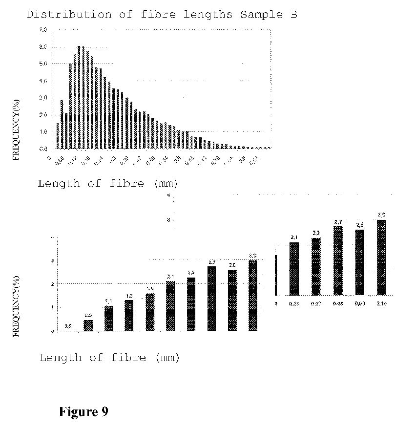
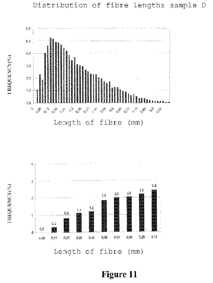
[0061] The results shown in Table 2 below are an evaluation of the distribution of fibre lengths within certain length ranges. The majority of fibres of all six Samples (A to F) after processing are 0.2-0.5 mm, which is considered to be the short fibre or fibre fragment range. This is also shown graphically in FIGS. 8-13. Each of these Figures (for respective samples) contains two graphs. The top graph in each of FIGS. 8-13 shows the distribution of fibres having lengths of <0.06 mm whilst the lower graph in each of these Figures shows the distribution of fibres having lengths of >0.1 mm.
TABLE 2
Distribution of fibre lengths (length weighted average length in length ranges) by weight %
0.001-0.2 0.2-0.5 0.5-1.2 1.2-2.0 2.0-3.2 3.2-7.6
mm mm mm mm mm mm
Sample A 22.8% 54.1% 23.1% 0.1% 0.0% 0.0%
Sample B 19.3% 51.0% 29.1% 0.3% 0.2% 0.1%
Sample C 19.1% 53.1% 27.8% 0.0% 0.0% 0.0%
Sample D 15.2% 48.7% 35.8% 0.3% 0.0% 0.0%
Sample E 22.5% 55.6% 21.8% 0.2% 0.0% 0.0%
Sample F 33.2% 57.2% 9.3% 0.2% 0.1% 0.0%
The fines content of the ground samples were investigated further by determining the fraction of the fines (fibres <0.2 mm) in each Sample based on the arithmetic average fibre length (AFL). This fraction for each Sample is compared to the length weighted fraction of fines (as per Table 2) is shown in Table 3 below. As can be seen from Table 3, the fines content of all Samples (A to F) is very high. The hemp cellulose Sample F, notably contained markedly more fine material than the wastepaper samples (A to E).
TABLE 3
Fine material contents
Fine material (<0.2 mm) Fine material (<0.2 mm)(arithmetic average) (length weighted average)
Sample % %
A 49.4 22.8
B 45.0 19.3
C 45.7 19.1
D 38.7 15.2
E 47.3 22.5
F 57.3 33.2
[0062] Further measurements of the diameter, wall thickness and calculated (curvature) parameters using the Fibrelab equipment show that samples A to E derived from wastepaper have similar values whereas sample F derived from hemp cellulose has smaller fibre dimensions and a smaller curvature. This result corresponds with the fibre lengths determined as well as with the fibre fragments present.
TABLE 4
Further fibre data
Fibre width Fibre wall thickness Fibre curvature
Sample µm µm %
A 16.5 3.8 17.9
B 16.2 3.8 18.1
C 16.4 3.8 17.3
D 17.0 4.1 19.3
E 17.0 4.0 18.0
F 13.9 3.3 16.2
Determination of the Water Retention Capacity (WRC) According to Zellcheming Fact Sheet IV/33/57
[0063] All Samples A to F (after grinding described above) were homogenised by mixing prior to sampling for determination of their Water Retention Capacity (WRC).
[0064] The Samples of fibrous material were dehydrated (to a solids content of approximately 25 wt %) on a G2 frit in the absence of a vacuum and transferred to a swell tube (according to DIN 53814). The swell tube was filled to approximately two-thirds capacity (resulting in a solids content of approximately 0.150 wt %). The swell tube was sealed with a plug and subjected to a centrifugal force of 3000 g for 15 minutes. Six parallel determinations were performed.
[0065] The water not participating in the swelling of the fibres was removed from the fibrous material by the centrifugation. The swelling water and the water retention capacity were gravimetrically determined by drying the fibrous material at 105° C. until a constant mass solids content was achieved. The results are shown in Table 5.
TABLE 5
Water Retention Capacity
Sample A B C D E F
Water Reten- % 841 742 1532 774 1138 1052
tion Capacity
The values of the water retention capacity are extremely high and atypical particularly compared to commercially available, strongly ground celluloses. The higher WRC generally equates to a denser material which when moulded and dried into a final product results in a product which has a lower tear or tensile strength but a higher load bearing capacity and Young's modulus. A preferred range for Water Retention Capacity is generally between 700 and 1200% as above this range, the low tear strength makes it difficult to form sheets—as was found with Sample C.
Material Properties: Physical/Strength Properties
[0066] Samples A to F were ground as described above and mixed with water in a mixer to a solids concentration in the range between 0.3 and 0.4 wt % (3 to 4 g/L) as per Table 8 below.
TABLE 8
Sample A B C D E F
Solids Concentra- wt % 0.367 0.379 0.351 0.379 0.354 0.351
tion in the mixer
[0067] The objective was to produce test sheets with an average grammage of mA of 80±2 g/m<2>, for use in subsequent strength testing according to the Rapid-Köthen method (in accordance with ISO 5269-2). It is noted that due to the very low dehydration capability of all of the Samples, the ISO 5269-2 test specifications had to be adapted by reducing the volume of filling water in the cylinder and varying the period of drop and suction to suit the required conditions for sheet forming for each of Samples A to F.
[0068] After producing the test sheets for each of the Samples, the test sheets were acclimatised in standard climate conditions (23 C.°/50% relative air humidity).
[0069] The grammage of the acclimatised test sheets was ten determined according to DIN EN ISO 536. The results of the grammage testing are shown in Table 9.
TABLE 9
Sample Grammage
Sample A B C D E F
Grammage g/m<2> 79.3 81.2 74.4 81.0 78.5 77.6
[0070] Due to the characteristics of the materials it was very difficult to produce test sheets with uniform grammage. This was especially the case of sample C wherein the targeted value (80±2 g/m<2>) could not be realised despite repeated corrections. This is due to the very high Water Retention Capacity (WRC) of the Samples. In order to compensate for the non-uniformity in grammage between the test sheets, the strength values have been corrected with respect to grammage.
[0071] The test sheets were subjected to thickness and apparent sheet density testing, the results of which are shown in Table 10.
TABLE 10
Sheet thickness and apparent sheet density
Sample A B C D E F
Thickness µm 84 88 78 89 80 81
Apparent sheet g/cm3 0.94 0.92 0.95 0.91 0.98 0.96
density
[0072] By virtue of the high proportion of very short, fine fibres, the thickness at the grammage strived for was small and the density very high. This corresponds to the normal behaviour at high packing densities that are achieved with very short fibres.
[0073] The test sheets were subjected to tensile testing according to DIN EN ISO 1924-2, the results of which are shown in Table 11 below.
[0074] The values for breaking force, elongation, breaking length and Young's modulus determined from this testing are not corrected with respect to the grammage, but are corrected with respect to the breaking length (represented as the Tensile Index):
TABLE 11
Tensile test results
Sample A B C D E F
Breaking force N 81.1 85.5 71.8 84.3 74.5 77.5
Elongation % 3.0 3.0 2.2 3.3 2.3 3.5
Breaking length m 7050 7250 6500 7100 6500 6700
Tensile Index Nm/g 69.1 71.0 63.7 69.7 63.7 65.9
Young's modulus GPa 7.85 7.77 7.88 7.48 7.92 7.92
[0075] From the results in Table 11, the tensile strength, expressed as tensile index, corresponds to that of ground cellulose. Whilst the tensile strength values for the Samples differ, there is little variation in the Young's modulus of the Samples which is high. The high Young's modulus of each of the Samples is indicative that the Samples can withstand tensile loads elastically for long periods of time. Without wishing to be bound by theory, it is expected that this is due to the high amount of fibrillation of the fibres and the subsequent linkages between the fibrillated fibres.
[0076] The test sheets were cut into strips and subjected to tear resistance testing according to DIN EN 21974. The results are shown in Table 12. The resistance to tearing is not corrected according to the grammage, only according to the tear index.
TABLE 12
Tear Resistance
Sample A B C D E F
Tear resistance (E) mN 222 280 181 294 195 215
Tear index Mn · m<2>/g 2.67 3.41 2.46 3.62 2.55 2.80
[0077] The tearing strength of all samples, measured on “standard” celluloses, is at a very low level, i.e. the resistance to tear is low. This can be attributed primarily to very short fibres.
[0078] In the claim which follows and in the preceding description, except where the context requires otherwise due to express language or necessary implication, the word “comprise” or variations such as “comprises” or “comprising” is used in an inclusive sense, i.e. to specify the presence of the stated features but not to preclude the presence or addition of further features in various embodiments.
[0079] It is to be understood that, if any prior art publication is referred to herein, such reference does not constitute an admission that the publication forms part of the common general knowledge in the art, in Australia or any other country.
WO2009111836
A METHOD FOR GRANULATING CELLULOSE FIBRES
A METHOD FOR GRANULATING CELLULOSE FIBRES
Inventor: ERNEGG MARTIN
Applicant: ZEO IP PTY LTD / ERNEGG MARTIN
A method for granulating cellulose fibres from a solid-liquid mixture comprising water and cellulose fibres, the method comprising: a) separating the mixture into wet fibres and water; and b) forming the wet fibres into a plurality of wet granules; c) drying the granules.
A METHOD FOR GRANULATING CELLULOSE FIBRES
Technical Field
The disclosure relates to a method for granulating cellulose fibres.
Background
The applicant has previously developed a process for producing moulded pieces out of cellulose fibres in which the specific gravity of the moulded pieces approaches that of pure cellulose, 1.5. The process involves finely chopping and grinding cellulose fibres in the presence of water into micro-fibres prior to forming a fibre-water mixture in which the cellulose fibre content is about 1-10% by weight. The process subsequently involves shaping and drying the mixture of cellulose fibres and water into the moulded pieces. Details of the process and the moulded pieces produced by the process are set out in United States Patent 6,379,594. It would be useful to be able to grind and chop the cellulose fibres into micro- fibres at one location and readily transport the micro- fibres to another location where they are used to form the moulded pieces . For example, one manufacturer may produce the micro-fibres for distribution to various other manufacturers to use in producing the moulded pieces at different sites. However, it is generally not economically viable to store or transport the cellulose micro-fibres when in the fibre- water mixture because: a) a wet mixture will biodegrade or otherwise deteriorate in storage unless it is treated before being stored, which is both difficult and costly; and b) transporting the fibre-water mixture requires the transportation of large volumes of water which has an unacceptable economic cost and environmental impact. Summary of the Disclosure
According to a first aspect of the present invention, there is provided a method for granulating cellulose fibres from a solid-liquid mixture comprising water and cellulose fibres, the method comprising:
(a) separating the mixture into wet fibres and water; and
(b) forming the wet fibres into a plurality of wet granules; (c) drying the granules.
Preferably, the mixture comprising water and cellulose fibres is prepared in accordance with the processes described in United States Patent 6,379,594, the contents of which are incorporated herein by reference . In an embodiment, the solid-liquid mixture to be granulated has a solids content of 1-30% by weight. In some methods, the solid-liquid mixture to be granulated may have a solids content of 1-6% by weight and in other methods may have a solids content of 7-30% by weight. The solids content of the mixture is at least mostly cellulose fibres and typically all cellulose fibres. However, the solid-liquid mixture may also comprise a pigment or other colorant which makes up a fraction of the solids content of the mixture. In an embodiment, the cellulose fibres in the mixture comprise cellulose micro-fibres. In this embodiment "micro-fibres" means fibres which are 0.1mm to 0.05mm in size.
In an embodiment, steps (a) and (b) occur simultaneously.
In another embodiment, step (a) occurs prior to step (b) .
The separation step may be a physical separation step. In an embodiment, the wet fibres have a solids content of 6-50% by weight, preferably 10-50% by weight, preferably 20-50% by weight, more preferably 30-40% by weight .
In an embodiment, the method also comprises the step of curling the cellulose fibres.
The step of curling the fibres may occur simultaneously with step (a) .
In an embodiment, step (a) comprises passing the mixture through a screw separator.
The screw separator may comprise a screw located in a cage . The screw may rotate inside the cage about its longitudinal axis.
In an embodiment, the mixture enters one end of the screw.
The water separated from the mixture in the screw separator may pass out through the cage.
The turning action of the screw of the screw separator may curl the cellulose fibres.
In an embodiment, step (b) also occurs whilst passing the mixture through the screw separator. The wet granules may be formed by the screw separator dewatering the mixture and preferably pass out of the end of the screw separator opposite to the end in which the mixture enters .
In another embodiment, step (b) occurs by using a granulator.
In another embodiment, step (a) comprises using centrifuge .
In another embodiment, step (a) comprises passing the mixture through a pressure filter, oscillating filter or any other suitable filter.
In another embodiment, step (a) comprises using capillary extraction.
In an embodiment, step (c) comprises heating the wet granules to no more than 220<0>C, preferably to a temperature of 14O<0>C to 160<0>C. Step (c) may also comprise extracting the evaporated water.
In another embodiment step (c) comprises using a swirl fluidizer to heat the granules and evaporate the water.
In an embodiment, steps (a) and (b) may occur prior to step (c) . In another embodiment, steps (a) , (b) and (c) occur simultaneously.
Steps (a) , (b) and (c) together may comprise spray drying the mixture to form dry granules comprising powder like particles. Any suitable spray drying process may be utilised and typically involves spraying the mixture through at least one nozzle.
In an embodiment, the mixture has a solids content of 1-20% by weight when fed into the spray dryer, preferably 1-6%. The dry fibres, after drying in the spray dryer may comprise the dried granules in the form of powder like particles.
The method may also comprise the step of (d) compressing the granules in larger granules. In an embodiment, step (d) comprises the step of pelletising the spray dried granules.
Any suitable pelletising process may be utilised and typically involves compacting multiple portions of the spray dried granules in dies . In an embodiment, the method may also comprise, prior to step (a) , heating the solid-liquid mixture, preferably to a temperature of approximately 160<0>C.
In an embodiment, the dried granules have a specific gravity of 0.2-1.0, preferably 0.2-0.7, most preferably 0.2-0.4.
The dried granules may have a water content of approximately 6-12% by weight.
According to a second aspect of the present invention, there is provided granules, produced according to the first aspect of the present invention.
According to a third aspect of the present invention, there is provided a method for forming an article from granules produced according to the first aspect of the present invention, the method for forming the article comprising the steps of:
(a) mixing the granules with water to form a solid-liquid mixture comprising cellulose fibres and water;
(b) shaping the mixture into the article/ and
(c) hardening the article by drying.
In an embodiment, the method also comprises the step of leaving the granules to soak in the water, preferably for 1-12 hours, more preferably 3-6 hours.
In an embodiment, the method also comprises the step of adding pigments or other colorants to the solid- liquid mixture. Generally steps (b) and (c) are carried out in accordance with the steps of shaping and hardening the work piece (article) as described in United States Patent 6,379,594.


Detailed Description of Embodiments
A method of granulating cellulose fibres from a solid-liquid mixture of cellulose fibres and water has been developed by the applicant. By granulating the cellulose fibres, the fibres can be stored for long periods without risk of biodegradation or other deterioration and readily transported between a site where the cellulose fibres are prepared for use in forming an article and another site or sites where the articles are formed, without needing to also transport large volumes of water. Generally, the method involves the steps of separating the mixture into wet fibres and water and forming the wet fibres into a plurality of wet granules which are dried.
The solid-liquid mixture to be granulated has a solids content of 1-30% by weight. The majority of the solids content and typically all of the solids content in the mixture is cellulose fibres, which have been ground and/or chopped into micro-fibres (0.01-0.5mm in length) .
A fraction of the solids content in the mixture may be a pigment or other colorant .
The solid-liquid mixture to be granulated may be prepared by any suitable method for refining (ie. grinding and/or chopping) the cellulose fibres, such as LC/HC refining, ultra friction grinding, high pressure homogenizing, extruding, steam explosion, ultra sonic treatment, enzymatic fibre separation and chemical treatment for example. In a particular embodiment, the solid-liquid mixture is prepared in accordance with the processes described in US 6,379,594.
In one embodiment, the method of the present invention involves physically separating water out of the mixture comprising water and cellulose fibres by passing the mixture through a screw separator. The screw separator comprises a screw which rotates about its longitudinal axis and is located in a cage. The mixture enters one end of the screw separator and is passed through the screw separator by the rotation of the screw. As this occurs, water is removed from the mixture by passing through the cage. The dewatered mixture exits the other end of the screw as wet granules having a solids content of 10-50% by weight, preferably 20-50% by weight, more preferably 30- 40% by weight. The separated water may or may not be collected for recycling.
The action of the screw causes the cellulose fibres to be curled. Advantageously, this acts against the cellulose fibres from binding together. This is desirable because if the cellulose fibres bind together they form strong interlinking bonds which are difficult to break without re-grinding and/or re-chopping, thus making it difficult to later use the granules by re-mixing with water and shaping to form articles. In other embodiments, the mixture is first separated into wet fibres and water by centrifuge, capillary extraction or by passing the mixture through a pressure filter, oscillating filter or any other suitable filter. After this separation step, the wet granules are formed from the wet fibres using a granulator.
After the wet granules are formed, they are dried by heating the granules to a maximum temperature of 220<0>C, preferably to a temperature of 140<0>C to 160<0>C, to evaporate the remaining water. The produced granules having a specific gravity of 0.2-1.0, preferably 0.2-0.7, more preferably 0.2-0.4 and a water content of approximately 6-12% by weight.
In another variation, the method for granulating cellulose fibres comprises spray drying the mixture comprising water and cellulose fibres. Any suitable spray drying process may be utilised and typically involves spraying the mixture through at least one nozzle. The mixture has a solids content of 1-20% by weight when fed into the spray drier, preferably 1-6%, and is typically pre-heated to about 16O<0>C. The granules produced by the spray drying are a plurality of powder-like particles. The granules formed in the spray drying process may be subsequently pelletised to form larger granules (pellets) using any suitable pelletising process. Typically, this involves compacting multiple portions of the spray dried mixture in dies.. However, in a further variation the dried granules are not pelletised but are left in the form of the powder-like particles.
The granules which may be in the form of pellets or powder produced according to the above embodiments may be packaged and transported as desired. They may also be used subsequently in a method for forming an article. This method comprises firstly mixing the granules with water to form a solid-liquid mixture comprising cellulose fibres and water. The granules may be left to soak in the water for a period of time, preferably for 1-12 hours, more preferably 3-6 hours. This is to enable the cellulose fibres to completely distribute into the water. Pigments or other colorants may be added to the mixture comprising water and cellulose fibres.
Once the cellulose fibres have been adequately mixed into the water, the solid-liquid mixture can then be shaped into the article and hardened by drying. Generally, the steps of shaping and hardening the article are carried out in accordance with the steps of shaping and hardening the work pieces (articles) as described in United States Patent US6,379,594.
EXAMPLES
In the following Examples, compositional percentages are weight percentages unless otherwise specified.
Example 1
A mixture of cellulose fibres and water was prepared firstly by dissolving Amcor RCW80 recovered wastepaper (shown in Figure 1) in water at 25<0>C under stirring conditions of 30rpm for 10 minutes in a drum mixer (shown in Figure 2) . The cellulose concentration in the mixture was 15%. This mixture (pulp) was then refined in a HC Andritz 22" refiner (shown in Figure 3) in accordance with the methods described in US6379594. Refining was conducted for different periods of time to prepare different samples. Sample 1 (Sl) was prepared by refining the pulp for 30 minutes and Sample 2 (S2) was prepared by refining the pulp for 50 minutes. A photograph of S2 as a wet pulp is shown in Figure 4.
The viscosity, compositional and dimensional properties of the refined samples were ascertained by conventional methods and are set out in Table 1 below. Table 1 : Refined Sample Properties
<img class="EMIRef" id="004009369-imgf000010_0001" />
Example 2
Sl was dewatered in a fan separator (shown in Figure 5) having a screen slot size of 0.1mm. The fibre content at the outlet of the fan separator was 36%. The stiff pulp from the outlet of the fan separator was then run through a fluid bed drier, specifically a Kason Double-Deck Circular Vibratory Fluid Bed Processor (shown in Figure 6) together with a second stream of Sl which was not dewatered (having a fibre concentration of 15%) . The batch running temperature during operation of the fluid bed drier was 160°. The granules produced by the fluid bed drier had a moisture content of 9% and are shown in Figure 7.
To demonstrate the workability of the dried Sl granules, they were then "regenerated" (rewetted) by mixing with water in a high friction mixer (shown in Figure 8) at 600rpm for 60 minutes to produce a fibre and water mixture having a fibre content of 15%. This mixture was then formed into a solid article in accordance with the processes described in US6379594. Various physical properties of this article produced from the regenerated Sl granules were compared to that of an article produced from the original as-formed Sl, set out in Table 2 below. Table 2
<img class="EMIRef" id="004009369-imgf000011_0001" />
Although the article produced from the regenerated S2 granules had satisfactory properties for use as a structural material, it was noted that the elasticity (Young Modulus) of the regenerated Sl granules was less than that of the as-formed Sl. Without wishing to be bound by theory, it is believed that this was due to insufficient mixing of the dry granules with the water in the high friction mixer which does not sufficiently disentangle the fibres from the entanglement that occurs as they are formed into the dry granules .
It was also found that the specific gravity of the dried granules should preferably not exceed 0.4. Again without wishing to be bound by theory, it is believed that granules which are created with a high density have greater fibre entanglement and thus are more difficult to disentangle upon regeneration by mixing with water, thus making the mixing process longer and less, economical.
Example 3
S2 was dewatered using a fluid press to increase the fibre content to 48% prior to being dried using a Gea swirl fluidizer (shown in Figure 9) . The air inputted to the swirl fluidizer had a temperature of 160<0>C. Dried granules of fibres were produced by the swirl fluidizer having a moisture content of 10%, and are shown in Figure 10.
To demonstrate the workability of the dried S2 granules, they were then "regenerated" (rewetted) by mixing with water in a high friction mixer at 600rpm for 60 minutes to produce a fibre and water mixture having a fibre content of 15%. This mixture was then formed into a solid article in accordance with the processes described in US6379594. Various physical properties of this article produced from the regenerated S2 granules were compared to that of an article produced from the original as- formed S2, set out in Table 3 below.
Table 3
<img class="EMIRef" id="004009369-imgf000012_0001" />
Although the article produced from the regenerated S2 granules had satisfactory properties for use as a structural material, it was noted that the elasticity (Young Modulus) of the regenerated S2 granules was less than that of the as-formed S2. Without wishing to be bound by theory, it is believed that this was due to insufficient mixing of the dry granules with the water in the high friction mixer which does not sufficiently disentangle the fibres from the entanglement that occurs as they are formed into the dry granules .
Example 4 S2 was first diluted by mixing in additional water to reduce the fibre content of the composition to 6% for suitable processing in a spray dryer. This watery composition of S2 was then pre-heated to 160<0>C prior to being spray dried by a Gea Mobile Mino Spray Dryer (shown in Figure 11) at a feed rate of 4L/hr to the nozzle and an atomization pressure of 1.6bar. The outlet temperature from the spray dryer was 95<0>C. Granules in the form of a dry powder (shown in Figure 12) were produced and were found to have a moisture content of 8%.
To demonstrate the workability of the dried S2 powder granules, they were then "regenerated" (rewetted) by mixing with water in a high friction mixer at 600rpm for 30 minutes to produce a fibre and water mixture having a fibre content of 15%. This mixture was then formed into a solid article in accordance with the processes described in US6379594. The E modulus (elasticity) and density of this article produced from the regenerated S2 granules was compared to that of an article produced from the original as-formed S2. It was found that the elasticity of the regenerated S2 granules was about the same as that of the as-formed S2. Without wishing to be bound by theory, it is believed that this was due to the very fine structure of the powder granules which enabled sufficient mixing with the water, even though the mixing time allowed was shorter than that provided in Examples 2 and 3.
Example 5
Cellulose fibre powder produced by spray drying S2 in accordance with Example 4 were pelletised using a Hosokawa Bepex GCS 200/80 pelletizer (shown in Figure 13) . The pellets produced are shown in Figure 14. In the claims which follows and in the preceding description, except where the context requires otherwise due to express language or necessary implication, the word "comprise" or variations such as "comprises" or "comprising" is used in an inclusive sense, ie. to specify the presence of the stated features but not to preclude the presence or addition of further features in various embodiments .
Related
Prior Art
Hemp Plastic Patents
Hemp Plastic Patents
CN203282693
Hemp-plastic composite material forming machine body with cooling water tank
A hemp-plastic composite material forming machine body with a cooling water tank comprises a tank body 2 and a feed hopper 1, wherein the tank body 2 is a built-in spiral-propelling cylindrical pipe body, and an inner ring groove is formed in the outer wall of an extrusion end of the cylindrical pipe body and used for forming the water tank 5 with a housing 4; the housing 4 is a cylindrical pipe body sleeved with the outer wall of the tank body 2, and a ring groove is formed in the inner wall of the cylindrical pipe body and used for forming the water tank 5 with the inner ring groove of the tank body 2; a water inlet pipe 3 and a water outlet pipe 6 both communicated with the water tank 5 are arranged on the housing 4. The hemp-plastic composite material forming machine body is simple and reasonable structure, low in cost, and suitable for a hemp-plastic composite material forming machine, and can meet requirement for continuous production.
CN103289427
Hemp/polymer composite material and preparation method thereof
The invention relates to a composite material and a preparation method thereof, particularly a hemp/polymer composite material and a preparation method thereof. The invention aims to solve the problems of difficulty in thermal degradation of hemp fibers, poor mixing uniformity of elongated hemp fibers and polyolefin plastic particles, and difficulty in feeding fiber knots into the extruder in the traditional extrusion technique. The hemp/polymer composite material is prepared from hemp, polymer and assistant. The method comprises the following steps: 1. mixing; 2. preparing a plate blank; 3. preheating, and carrying out hot pressing; and 4. setting by cooling. The invention adopts a compression molding mode to prepare the hemp fiber/plastic composite material. The processed product can have wide size and various bending shapes, and can be secondarily molded into other products. The invention is used for preparing the hemp/polymer composite material.
CN103214873
Natural hemp fiber reinforced plastic-wood composite material
The invention discloses a natural hemp fiber reinforced plastic-wood composite material. The natural hemp fiber reinforced plastic-wood composite material is characterized by being obtained by the following steps of: mechanically mixing 5-30 parts of hemp fibers, 21-66 parts of wood fibers and 21-66 parts of plastic fibers, and adding the mixed materials to a double-roller open mixing machine to plasticize and mix, controlling the temperatures of front and the rear rollers at 160 DEG C and 170 DEG C in the mixing process, respectively, and mixing for 8-15 minutes until the system is uniformly mixed; crushing the uniformly plasticized materials by a crusher until the particle diameter of the materials does not exceed 20 mm; and carrying out extrusion molding by using a double-screw extruder to obtain a board sample. The natural hemp fiber reinforced plastic-wood composite material has the advantages of introducing hemp fibers of a certain proportion to the plastic-wood formula by adopting a special process, so that various mechanical performances of the plastic-wood material are effectively improved.
KR20110088801
A HEMP COMPRISING PLASTIC AS A MAIN COMPONENT...
PURPOSE: A plastic having hemp and a manufacturing method thereof are provided to improve an environment-friendly effect using hemp with antibacterial and deodorizing properties. CONSTITUTION: A manufacturing method of a plastic having hemp is as follows. The stem or heart of hemp is cut and is washed and dried. The dried hemp is put into a crusher and is crushed to separate cellulose. The crushed hemp is molded in a cotton form. A polypropylene pellet fiber is formed by heating and fusing polypropylene pellet and solidifying the heated and fused polypropylene pellet. The hemp fiber and the polypropylene fiber are heated and are pressed.
CN102002178
Continuous long fiber reinforced polyolefin plastic wood composite material and preparation method thereof
The invention relates to a plastic wood composite material and a preparation method and a co-extrusion die thereof, in particular to a continuous long fiber reinforced polyolefin plastic wood composite material and a preparation method thereof. The composite material consists of the following components in percentage by weight: 20 to 80 percent of polyolefin plastic, 0 to 80 percent of wood fiber, 0 to 80 percent of mineral filler, 0 to 10 percent of lubricating agent, 0 to 5 percent of antioxidant, 0 to 5 percent of ultraviolet absorbent, 0 to 10 percent of coupling agent, 0 to 10 percent of pigment and 0 to 30 percent of reinforcing fibers; the reinforcing fibers are surface modified or unmodified glass fibers, jute fibers or hemp palm fibers; and the reinforcing fibers are continuously extended along the length direction of the polyolefin plastic wood composite material, and the number of the reinforcing fibers is at least one beam. The reinforcing fibers are continuously extended and distributed in the polyolefin plastic wood profile; and when the plastic wood profile is forced during use, the continuous extended fibers can quickly transfer the local force to the whole profile so as to greatly improve the strength and the impact resistance of the plastic wood profile.
DE102007054549
Producing natural fiber plastic composite material by drying the natural material such as hemp...
The method for the production of natural fiber plastic composite material for the production of different products, comprises drying the natural material such as hemp, hay, flax, straw and rice husks and/or wood in the form of fiber, splinter, shred or flour, crushing the wood raw materials and then compounding with a plastic melt and/or additives for the natural fiber plastic composite material. The wood raw materials, solid or liquid plastic and if necessary additives are mixed through kneading and simultaneous pressing in a closed system in a discontinuous production process. The method for the production of natural fiber plastic composite material for the production of different products, comprises drying the natural material such as hemp, hay, flax, straw and rice husks and/or wood in the form of fiber, splinter, shred or flour, crushing the wood raw materials and then compounding with a plastic melt and/or additives for the natural fiber plastic composite material. The wood raw materials, solid or liquid plastic and if necessary additives are mixed through kneading and simultaneous pressing in a closed system in a discontinuous production process. The wood raw materials are crushed during the mixing process and water contained in the wood raw material is evaporated through heat energy produced during kneading and pressing process through friction. The surface of the wood raw materials is activated through a further introduction of frictional warmth and/or its reaction capability is increased. The plastic is melted by the frictional heat and the wood raw material is compounded with the plastic melt or with a supplied plastic melt and/or if necessary with additives for a homogeneous natural fiber plastic composite material. The plastic is processed in the form of granulates, cubes or powder. The additive is bonding agent, ultraviolet protective additives and color pigments. An independent claim is included for a device for the production of natural fiber plastic composite material.
CN101343406
Heat-proof polylactic acid-starch alloy system full-biodegradation material and preparation thereof
The invention discloses temperature resistance type polylactic acid-starch alloy system whole biodegradable material and the preparation method. The temperature resistance performance of the polylactic acid can be raised above 85 DEG C by adopting the temperature resistance type polylactic acid-starch alloy system whole biodegradable material, simultaneously, fully plastic material is presented when the temperature is above 120 DEG C, the temperature resistance type polylactic acid-starch alloy system whole biodegradable material has the processing property and the practical performance of common plastics, and the applicable range of the polylactic acid is enlarged.; The temperature resistance type polylactic acid-starch alloy system whole biodegradable material is made of the raw materials according to the percentage by weight: polylactic resin accounting for 50 percent to 70 percent, grafting modified starch accounting for 10 percent to 20 percent, natural hemp fiber powder accounting for 5 percent to 20 percent, superfine nucleating agent accounting for 5 percent to 20 percent, reversible cross-linking agent accounting for 1 percent to 5 percent, aliphatic chain-extending agent accounting for 1 percent to 5 percent, coupling agent accounting for 1 percent to 5 percent, plasticizer accounting for 1 percent to 5 percent, carboxy compatilizer accounting for 1 percent to 5 percent and creep resistant inorganic powder accounting for 5 percent to 20 percent.
CN101307185
Plant fiber polymerization wood and method for manufacturing same
The invention relates to artificial composite wood, in particular to a plant fiber polymer wood and a method for making the same. The plant fiber polymer wood is made form the following materials in percentage by weight: 50 to 85 percent of plant fiber powder, 10 to 45 percent of plastic resin, 0.5 to 1.5 percent of coupling agent, 2 to 5 percent of foaming agent, 0.5 to 1.5 percent of blowing promoter, 1 to 2 percent of plasticizer, 0.5 to 1 percent of nucleating agent, and 0.5 to 3 point of lubricating agent, wherein the plant fiber powder is one or a plurality of kinds selected form wood meal, powdered rice hull, powdered straw( corn stalk, sorghum stalk, wheat straw, straw, sunflower stalk, egg plant stalk, bean stalk, haulm, hemp stalk and other crop stalks), brushwood powder, weed powder, and peanut and seed shell powder. The artificial composite wood has the characteristics o saving wood material, allowing for recycling, contributing to environment protection, along with high strength, low cost, long service life. The process is simple, scientific and reasonable.
US2002148190
Hemp building material
A hemp building material for creating a reinforced structure utilizing hemp fibers. The hemp building material includes an elongate structure having a plurality of bast fibers contained within the elongate structure. The bast fibers are orientated substantially parallel to the longitudinal axis of the elongate structure. The bast fibers are preferably positioned within the lower portion of the elongate structure to provide tensile resistance to the elongate structure during the supporting of a vertical load. The elongate structure may have various configurations and may be constructed of various materials such as but not limited to plastic and composite materials.
US2003066262
Hemp building material
A hemp building material for creating a reinforced structure utilizing hemp fibers. The hemp building material includes an elongate structure having a plurality of bast fibers contained within the elongate structure. The bast fibers are orientated substantially parallel to the longitudinal axis of the elongate structure. The bast fibers are preferably positioned within the lower portion of the elongate structure to provide tensile resistance to the elongate structure during the supporting of a vertical load. The elongate structure may have various configurations and may be constructed of various materials such as but not limited to plastic and composite materials.
JP2006089862
METHOD FOR PRODUCING PAPER PLASTIC MOLDED PRODUCT OF NON-PAPER PULP PLANT FIBER
PROBLEM TO BE SOLVED: To provide a method for producing a paper plastic molded product of non-paper pulp plant fiber. ;SOLUTION: The method comprises the operation steps of (a) scouring, (b) bleaching, (c) washing with water, (d) dewatering, (e) grinding, (f) slurry diffusion, (g) plastic slurry formation, (h) paper plastic formation, and (i) demolding. This method affords the effects of cutting the production cost of paper plastic products and sustaining the global ecological environment through using olive, hemp and coconut husk material as conventional industrial wastes as the primary aggregates for the paper plastic products.
JP2004143401
FIBER-REINFORCED PLASTIC USING PLANT FIBER
PROBLEM TO BE SOLVED: To provide a fiber-reinforced plastic exhibiting less amount of residue after its burning treatment and having an equivalent or a higher mechanical strength than that of the fiber-reinforced plastic using a glass fiber. ;SOLUTION: This fiber-reinforced plastic containing fibers in a plastic material 1 is characterized by using a plant fiber sheet 2 obtained by forming lignocellulose fibers 3 as a sheet shape. As the fibers of the plant fiber sheet 2, the lignocellulose fibers consisting mainly of cellulose and lignin can be used. Concretely, the fibers collected from the bast fibers of such as kenaf, linen, ramie, hemp, jute, etc., or the plant fibers collected from the strings of stems or leaves of manila hemp, sisal hemp, etc., are cited. These fibers are composed of, in addition to the cellulose and lignin, components such as hemicellulose, pectin, etc.
JPH11315197
FORMING MATERIAL FOR BIODEGRADABLE PLASTIC AND BIODEGRADABLE FORMED PRODUCT USING THIS MATERIAL
PROBLEM TO BE SOLVED: To obtain the subject forming material capable of producing a formed material by extrusion molding or injection molding even in the case where it has a lower molecular weight than the conventional polymer for injection molding by compounding a hydroxycarboxylic acid oligomer having a specific molecular weight. SOLUTION: This forming material is obtained by compounding (A) a hydroxycarboxylic acid oligomer having a molecular weight of 15000 or less, preferably 10000 or less, more preferably in the range of 1000-5000 optionally with (B) 70 wt.% or less (0 is not included), preferably 30-60 wt.% of a mineral filler, (C) 30 wt.% of less (0 is not included), preferably 10-20 wt.% of a plant fiber, or the like. An example of the component A is preferably a homopolymer or copolymer prepared by using lactic acid and/or glycolic acid as a monomer, more preferably a homopolymer of lactic acid. Examples of the component B include calcium carbonate, mica, talc, alumina, silica, or the like. Examples of the component C include hemp, jute, cannabis, cellulose or the like.
GB191109559
Plastic Phenolic Condensation Product.
Coating-compositions; impregnating-compositions.-Infusible phenol formaldehyde resins, produced, for example, by addition of formaldehyde or hexamethylenetetramine to fusible resins and heating, have incorporated with them a halogen - substituted phenol or naphthol at some stage of their formation prior to hardening. An additional organic substance, such as naphthalene, may also be added to the resin to lower the melting point of halogenphenol used. When hexamethylenetetramine is employed as hardening-agent, a compound of ammonia with a chlorphenol is formed within the mass. This product may also be separately formed and added to the resin. When the composition is .employed in sheet form for roofing and other building purposes, other noninflammable halogen compounds may be used, such as chlornaphthalenes, benzenes, toluenes, anthracenes, and tetrachlorethane. A mineral pigment or filler such as plaster of paris, barium sulphate, sand, clay, infusorial earth, wool, silica, mica, &c. and a fibrous substance such as hemp, cotton flax, jute, hair, wood pulp, asbestos, or filamentary metal such as wire-gauze may also be used. Fusible phenol formaldehyde resin may be mixed with sufficient formaldehyde or its equivalent and dissolved in a suitable solvent, the fibrous material added, and the mass thoroughly mixed. The solvent is then removed, and the dried mass, after being comminuted, pressed while heating. When flexible sheets are required, canvas or other fabric is impregnated with a solution of the soluble resin, together, if necessary, with the further quantity of formaldehyde necessary for hardening, and the solvent evaporated. The fabric is then heated under pressure. The resulting sheets may be used for roofing. According to a further method, sheets of the finished product are reinforced by calendering on to a coarse woven fabric, for example, of metal wire, or the fabric may be inserted into the comminuted product before pressing into sheets. Specifications 16,247/99, 3496/11, and 3498/11, [all in Class 70, India-rubber &c.], are referred to.
GB191307038
Improvements in and relating to the Manufacture of Artificial Wood.
Fibrous plastic compositions. - Sawdust, ground in water and preferably in the presence of per cent of soda or potash, is mixed with cellulose acetate and with caustic soda or potash, rosin size, or soda and alum. If desired, jute or hemp waste that has been steeped in caustic may be added, and the sawdust, while being treated with soda or potash, may be subjected to alternate vacuum and pressure as described in Specifications 2018/10, [Class 96, Paper &c.], and 16,085/12. The composition is compacted by alternate drying and pressing. The proportions preferred are 70 parts of sawdust, 20 parts of jute or hemp waste, and 5 parts each of cellulose acetate and of soda &c.
HUT37159
METHOD FOR PRODUCING FIBRE REINFORCED THERMOSETTING PLASTIC BY USING OF FIBROUS MATERIAL OF NATURAL BASE
The components are made of synthetic resins, esp. those based on phenol and creosol. The synthetic resin is mixed with reinforcing material, dried and shaped by pressing. The reinforcing material is a natural fibre, such as flax, hemp, etc. chopped up and arranged as required.
Hemp fiber for plastic reinforcement and preparation method thereof
KR101350949
CZ23867
Composite material with natural fiber fillers based on hemp for manufacture of plastic parts
US4122145
PROCESS AND APPARATUS FOR PRODUCING PLASTIC-COATED PRODUCTS,FIRST OF ALL FIBROUS PRODUCTS WITH METAL WIRE OR HEMP HEART
CZ20110855
Composite material with natural fibrous filling agents based on hemp for producing plastic components
HempCrete Patents
ENVIRONMENT-FRIENDLY CONCRETE COMPOSITION...
KR101443674
KR101443669
The present invention provides a concrete composition including, based on 100 parts by weight of cement: 10 to 40 parts by weight of a mixture consisting of 10 to 90 weight% of a hemp solution in least one form of a powder, a concentrate and an extract and 10 to 90 weight% of a hemp stem having a length of 0.5 mm to 5 cm; 10 to 30 parts by weight of a foaming particle; 5 to 15 parts by weight of a flame retardant including liquefied ammonium pyrophosphoric acid as a flame retardant supplement; 10 to 25 parts by weight of a binder; and 0.01 to 10 parts by weight of a high efficiency water reducing agent, which includes 80 to 95 weight% of naphthalene water reducing agent and 5 to 20 weight% of a polycarboxylic acid high efficiency water reducing agent, to make an amount of air in a range of 4 volume% to 6 volume% in a concrete, wherein 1 to 15 parts by weight of a viscosity modifier selected from the group consisting of trimethane ester, benzoic acid ester, ethylcyclohexane, 2,2,4-trimethyl-1,3,-petanedioldibutyrate and a filling agent selected from the group consisting of a silica, an acryl powder and quartz based on 100 parts by weight of the cement are further included. The building interior material composition according to the present invention improves durability and adds sound-absorbing power, antibacteral power, deodorization, insect repellent property, heat insulation, and ultraviolet ray blocking property while emitting far-infrared radiation, removing harmful waves and easily manipulating moisture by using a bio-friendly hemp which may be obtained from nature.
Basement deforming seam for civil engineering
CN203768950
The utility model discloses a basement deforming seam for civil engineering. The basement deforming seam comprises a basement concrete cube and a deforming seam embedded into the basement concrete cube. Angle steel is arranged on the basement concrete cube. An upper end opening of the deforming seam is an arc funnel opening which is fixed on the angle steel through a fixing piece. A waterproof mortar layer is wrapped on the outer portion of the arc funnel opening. Pitch fibers, a water stopping belt, asbestos hemp threads, a water stopping belt, a pitch wood-wool plate and a water stopping belt are arranged in the deforming seam from top to bottom in sequence. A cone-shaped flow guiding groove is formed above each water stopping belt. Epoxy resin is arranged in the cone-shaped flow guiding grooves. The basement deforming seam is simple in structure, the whole structure is better fixed through an arranged disc bolt, three waterproof material layers are arranged in the deforming seam, the waterproof function is good, the flow guiding grooves are formed above the water stopping belts, horizontal permeating is avoided, a waterproof mortar coating layer is arranged on the inner wall of the deforming seam, and waterproof effect is improved.
Transformer substation enclosure pre-cast concrete coping
CN203701716
The utility model discloses a transformer substation enclosure pre-cast concrete coping. C30 bare concrete is adopted, the width B is 0.39 m, the length L generally ranges from 1.00 m to 1.50 m, the thickness H is 100 mm, reinforcing steel bars are assembled in the transformer substation enclosure pre-cast concrete coping, water is drained outwards through a single slope, larmiers are formed in the positions, 20 mm away from the edges, of the two sides of the bottom of a coping body (1), the widths of the larmiers are 15 mm, the depths of the larmiers are 10 mm, and a reinforcing steel bar lifting hook (2) 12 mm in diameter is arranged at the position, 300 mm away from the end, of the pre-cast concrete coping body (1). Before the transformer substation enclosure pre-cast concrete coping is installed, cement mortar (3) 20 mm in thickness is evenly laid at the top of an enclosure to carry out leveling, 10-mm gaps are reserved between the transformer substation enclosure pre-cast concrete copings and filled with bituminous hemp fibers, and the surfaces of the gaps are sealed through silicone weather-proof glue. After the transformer substation enclosure pre-cast concrete coping is completely installed, the lifting hook is cut off, and zinc spraying antiseptic treatment is carried out on the surface. The transformer substation enclosure pre-cast concrete coping is simple, reliable in quality, free of influencing the ambient construction environment and relatively low in manufacturing cost, and cracks even breakages caused by differential settlement of an enclosure foundation or temperature stress caused by the excessively large length can be effectively avoided.
Water pool expansion joint water leakage repairing method
CN103821109
The invention discloses a water pool expansion joint water leakage repairing method, which is characterized by comprising the following steps that (A) a soil layer at the back water side of an expansion joint is cleared; (B) temporary sealing and blocking is carried out, asbestos hemp threads are sealed and plugged at the water seepage part of the expansion joint, then, a needle tube is used for injecting water foaming polyurethane, and the water leakage part is temporarily sealed and blocked to the state without water leakage; (C) support convex heads are cast; (D) wall posts are cast; (E) filing is carried out: a sealing plate is arranged at the bottom of a gap of the two wall posts in a sealed way, then, flowing sealing glue is filled in a gap formed above the sealing plate, and a first sealing glue sandwich layer is formed; (F) the soil layer at the back water side of the expansion joint is filled back. The water pool expansion joint water leakage repairing method has the advantages that the water leakage is sealed and plugged, the deformation quantity of the original design is remained, the production halt is not needed, the work period is short, the cost is low, and the water pool expansion joint water leakage repairing method can be widely applied to sewage plant buildings and water-failure-free repairing of large-scale concrete pipelines.
Cement straw composite plate and production technological method
CN103771790
The invention relates to a cement straw composite plate and a production technological method. The composite plate finished product is prepared by taking crop straws (cotton stalks, wheat straws, corn stalks, sorghum stalks and hemp stalks) as an enforcement material, taking cement as an adhesive, adding a special additive, mixing with an auxiliary agent and water, and performing stirring, paving, compacting and mold locking, heat curing, demolding, trimming and normal-temperature curing. The cement composite plate is widely applicable to suspended ceiling plates, exterior wall plates and roof board plates of various buildings, has the characteristics of wood and concrete, and also has excellent mechanical properties.
Pipeline structure penetrating through roof
CN203429915
The utility model discloses a pipeline structure penetrating through a roof. The pipeline structure is characterized in that an extrusion-molding insulation board is arranged outside a roof wall and is 60-70mm thick, an expanded perlite insulation board is arranged on a roof structural slab which is 40-50mm thick, fine aggregate concrete is arranged on the expanded perlite insulation board and is 30-40mm thick, waterproof mortar is arranged on the fine aggregate concrete, internal corners of the waterproof mortar are arc, a felt is arranged on the waterproof mortar, and a clearance of 15-20mm is formed between a pipeline and the expanded perlite insulation board and is filled with hemp threads.
Self-supporting, curved ceiling plate without subconstruction of reinforced concrete
DE102012016044
The self-supporting, curved ceiling plate is made of laminated wood, metal, plastic or impregnated natural fiber material. The renewable raw materials such as straw, hemp or wood fibers are considered as natural fiber materials. The natural fibers are knitted into a continuous fibrous web and are pressed into a curved shape, and the plate is treated with an impregnation. The preload is incorporated in the form of steel bands or cords for reinforcement between the edges of the plate.
Deformable joint structure of concrete trestle step and floor
CN203361360
The utility model provides a deformable joint structure of a concrete trestle step and a floor. A trestle stepping structure is layered. An embedded iron piece is arranged on a beam of a floor board. A deformable seam with a certain distance is reserved between the trestle step and the floor. An iron sheet is usually installed on the upper end faces of the concrete trestle stepping structure and the floor. A U-shaped structure is formed by the iron sheet in the deformable seam. The U-shaped iron sheet extends in the deformable seam and is filled with bituminous hemp fibers. A bituminous wood-wool board is laid on the bituminous hemp fibers. A cement mortar cushion layer is laid on the iron sheet. A shaped steel plate covers the cement mortar cushion layer. The end portion, close to the floor, of the steel plate is welded and fixed to the embedded iron piece. A transverse gap is reserved between the steel plate and the floor. The gap is sealed through a polyurethane sealing material after being welded. According to the deformable joint structure of the concrete trestle step and the floor, the requirements for the deformable seam in a large-scale project can be satisfied, meanwhile, the functions of settlement, earthquake resistance, stretching and contraction can be achieved, and the waterproof performance is improved.
Deformable joint structure of concrete trestle floors
CN203361011
The utility model provides a deformable joint structure of concrete trestle floors. A deformable seam of a certain width is formed between the two trestle floors. The lower end face of the joint portion of the trestle floors is usually sealed through an iron sheet. The length of the lower end face connecting iron sheet between the two sides of the deformable seam is larger than the actual length of the deformable seam, namely the lower end face connecting iron sheet has a certain surplus amount. The deformable seam is filled with bituminous hemp fibers. An iron sheet is laid between the upper end faces of the two trestle floors which are flush with each other and located on the upper portion of the deformable seam. The length of the upper end face connecting iron sheet between the two sides of the deformable seam is larger than the actual length of the deformable seam, namely the upper end face connecting iron sheet has a certain surplus amount. Each iron sheet is additionally provided with a waterproof coiled material so that the secondary waterproof function can be achieved. A cement mortar cushion layer is laid on each waterproof coiled material. The portions, on the portion of the deformable seam, of the waterproof coiled materials are respectively sealed through a bituminous mastic material. According to the deformable joint structure of the concrete trestle floors, the requirements for the deformable seam in a large-scale project can be satisfied, meanwhile, the functions of settlement, earthquake resistance, stretching and contraction can be achieved, and the waterproof performance is improved.
Pavement joint sealing material
CN103408924
The invention discloses a pavement joint sealing material. The pavement joint sealing material comprises the following components in parts by weight: 60-80 parts of polyether polyol, 40-50 parts of diphenylmethane diisocyanate, 10-18 parts of hemp stem based lignocelluloses, 5-10 parts of nylon, 2-10 parts of light stabilizer, 1-6 parts of inorganic nanometer oxide, 10-20 parts of antioxygen, 1-6 parts of hammer milled glass fiber, 2-8 parts of coupling agent, 6-10 parts of xylene, 1-5 parts of foaming inhibitor, and 3-10 parts of waterproof agent. Under a synergistic effect, the components can improve the uvioresistant capability of the sealing material, so as to improve the weather resistance capability and ageing resistance capability, effectively prolong the service life of the sealing material to over 20 years, and effectively reduce the probability of bubbles and cracks in high-humidity environment. The pavement joint sealing material also has the advantages of good elasticity, caking property, endurance and weather resistance, strong binding force and convenience in construction, can endure long-term stretching, compression and vibration, and cannot be destroyed by thermal expansion in the joint, repeated stretching and compression; when the sealing material is paved on a cement concrete pavement, the quality of the cement concrete pavement can be improved, and the service life of the pavement is effectively prolonged.
Through floor pipeline leakage-prevention structure with sleeve
CN203258206
Deformable connection structure of concrete landing stage steps and building surface
CN103352550
CN103352422
Multi-ply waterproof structure of basement
CN203222830
Deformation joint with rubber waterstop
CN203200793
Basement multiple impervious deformation joint
CN203200791
Dry hanging curtain wall fixing structure
CN203145265
Quake-proof energy-saving concrete structure
CN103255835
METHOD FOR CONSTRUCTING A BUILDING USING BRICKS CONNECTED USING DRY JOINTS
US2013205703
Expansion joint structure of cast-in-place reinforced concrete baffle
CN203129189
Waterproof structure of channel
CN203066265
CN203066120
Production method of lightweight ecological fish shelter
CN103081827
Bridge cast-in-place pile non-chisel pile head
CN202899122
Granite ground structure
CN202787879
Concrete wall settlement joint
CN202730976
Bridge cast-in-place pile chiseling-free pile head and construction method thereof
CN102926380
Roofing waterproof structure with deformation joint
CN202706349
Basement deformation joint structure
CN202706232
Basement expansion joint structure
CN202689200
Water proof structure of basement expansion joint
CN202689053
Settlement joint structure for concrete wall
CN202672372
Joint sealing structure for externally-hung prefabricated slab
CN202577614
Concrete wall window hole structure
CN202544166
Roof water proof construction with expansion joint
CN202530640
Concrete dam joint waterproof structure
CN202530427
Waterproof structure for expansion joint of soleplate
CN202500160
Basement deformation joint
CN202466641
Glass cloth deformation joint
CN202466637
Construction technology for fair-faced concrete wall with rope rib mark-texturized surface
CN102650159
Building template pad
CN202324627
Cantilever type cover plate deformation joint structure of accessible roof and construction method
CN102518216
Plugging system of dewatering well
CN202175962
Advance water stop construction method...
CN102373715
Method for reinforcing e.g. prefabricated part...
DE102010022396
METHOD FOR CONSTRUCTING EMP PROTECTION ROOM
KR101033864
Hoisting device for imperforate concrete pillar
CN201802079
Pet door...
DE102009051092
Device for projecting hemp concrete...
FR2965576
Structure for ecological engineering method
CN201722694
Process for pretreating raw materials of sunflower stalk composite boards and pressing assemblies
CN101941227
Device for projecting concrete i.e. hemp concrete...
FR2964059
Building panel for use in e.g. balcony...
DE102009022407
KRAFT PAPER HAVING FIBROUS PATTERN
JP2010150691
Insulation panel and method of production
EP2295666
Preparing and projecting low density hemp concrete...
FR2957016
Waterproof construction of basement soleplate and construction method thereof
CN101694100
Concrete i.e. hemp concrete projection device...
FR2951986
Prefabricated non-bearing wall for use in construction system...
FR2952660
Gas tank mat foundation connection structure and construction method
CN101644060
Outer insulation or construction box...
FR2947582
Underlay, for casting concrete components...
DE102008041504
Method for demolishing ultra high cast-in-place pile head
CN101634147
Solid ecological repairing bamboo raft member in riverbank and manufacturing method thereof
CN101545252
Method for preventing expansion damage of sodium silicon concrete
CN101434098
HEMP CONCRETE MIXTURES AND MORTARS, PREPARATION METHOD AND USES
PT1406849
Non oil coated construction form
US6117522
COMPOSITE DRYING OIL
RU2146688
INTERIOR AND EXTERIOR VENEER BOARD USING WASTE SYNTHETIC FIBER...
KR20010066978
STRUCTURE FOR WATERPROOFING SLAB FLOOR WITH EXPANDING JOINT
KR20010000022
BAMBOO FENCE ASSEMBLING METHOD...
JP2008175043
PROTECTIVE SHEET FOR WALL SURFACE OF CONCRETE STRUCTURE
JP2008184802
STRUCTURE FOR GROWING ANIMALS AND PLANTS ON IT
JP2004107174
COMPOSITION FOR FORMING PLANT-GROWING POROUS CONCRETE BAS...
JP2003235345
VEGETATION CONCRETE BLOCK AND VEGETATION CONCRETE BLOCK CONSTRUCTION
JPH10195898
SOUND ABSORPTION BOARD, AND SOUND ABSORPTION AND SOUND INSULATION STRUCTURE
JPH07189358
GREENING BY AERIAL SEEDING AND GREENING MATERIAL FOR AERIAL SEEDING
JPH09154323
WET FINISHING OF CONCRETE BODY
JPH09110557
RAW MATERIAL AND MANUFACTURE FOR BUILDING FINISHING WALL MATERIAL
JPH1162053
PRODUCTION OF HIGHLY DURABLE CONCRETE STRUCTURAL MATERIAL
JPH0881252
ROCK WORK GREENING METHOD
JPH0748823
CONCRETE BLOCK
JPH1037377
MAT FOR AGGREGATE EXPOSURE FINISHING
JPS6433354
MANUFACTURE OF BUILDING PANEL
JPH0235150
FIBER REINFORCED RESIN TUBULAR MEMBER
JPH06328624
SLIPPAGE-PREVENTING RUBBER MAT FITTED WITH PROTECTION AGAINST DAMAGE, BEING PLACED ON ROAD
JPH07233505
Improvements in and relating to Concrete Piles.
GB191228511
Head for Reinforced Concrete Piles.
GB191217682
METHOD OF MAKING A GLASS-FIBRE-REINFORCED CEMENTITIOUS COMPOSITION
GB1511270
Production of light-weight concrete products
GB1089777
A backing for a surface structure such as a floor
GB1016610
GYPSUM PLASTER PRODUCTS
GB1438404
Improvements in or relating to concrete and the like piles
GB732494
SIMULATED GRANITE AND ITS PREPARATION
GB1516920
LAMINATED CONSTRUCTION FORMED IN PART FROM CEMENTITIOUS MATERIAL
GB1398731
Improvements in and relating to the treatment of ramie, flax, hemp ...
GB185865
Improvements in and relating to the manufacture of armoured or reinforced concrete pipes or similar bodies
GB383952
Reinforced concrete ship moulds
GB167818
Interlocking building brick
GB2454259
Improvements in and relating to piles
GB788633
Improvements relating to pipes and conduits
GB248920
Improvements in and relating to brushes and brooms
GB410925
Improvements in electric cable conduits
GB361729
ALTERING THE PROPERTIES OF CONCRETE BY ALTERING THE QUALITY OF THE INTERGRANULAR CONTACT OF FILLER MATERIALS
GB1273693
Acoustically-insulated and thermally-insulated multilayer prefabricated inside wall, outside wall, and iso-cement compound wall
FR2709504
Method for casting concrete containing a filler composed partly by petrified hemp stalks...
FR2645067
Concrete e.g. hemp concrete...
FR2915702
Process for mineralising renewable raw materials...
EP1108696
Process for the treatment of a hemp by-product...
EP0384815
Concrete roof stone...
DE102004063271
Natural fibre-reinforced building material
DE19736527
Ecologically good loudspeaker housings - are made up of hollow fibre-reinforced concrete component
DE4004780
COMPOUND OF CONCRETE AND MORTAR WHICH CONTAINS HENEQUEN HEMP FIBRES.
CU22186
Water-proof heat insulation tile
CN2619994
Low-density concrete e.g. hemp lime concrete
FR2923242
Related Hemp Tech Patents :
Method for processing steaming rotting
CN101109157
Technique for separating hemp seed and husk kernel
CN101181092
New technology for producing hemp fiber
CN118687