Greg
KETTERMAN
Oscillating Foil Propulsion ( Hobie Mirage Drive )
Oscillating Foil Propulsion ( Hobie Mirage Drive )
http://www.hobiecat.com/kayaks/features/miragedrive/
Mirage Drive
 Turbo Drive
Turbo Drive
Specifications
Weight: 6.6 lbs / 3.0 kg
Features Revolutionary Propulsion System
Hands-Free Kayaking
Adjustable Mechanism Accommodates a Wide Range of Pedalers’ Heights
Durable Construction of Injection-Molded Plastics and Stainless Steel Fittings
Self-Cleaning Mechanism (Resists Wear from Sand and Other Particles)
Easily Removable for Transport and Storage
Hands-Free Kayaking
Adjustable Mechanism Accommodates a Wide Range of Pedalers’ Heights
Durable Construction of Injection-Molded Plastics and Stainless Steel Fittings
Self-Cleaning Mechanism (Resists Wear from Sand and Other Particles)
Easily Removable for Transport and Storage
Turbo Fin Kit --
Hobie Engineers and Hobie Mirage kayak users report 10% increases in speed and more.Top end speed and a slower cadence for cruising are all achieved with this larger and more efficient fin design. Will require more effort to pedal. Adjustable fin tension allows for low end torque or top end speed to meet the desires of the pedaler. The ST Turbo kit does it. Fits any Hobie Mirage Drive. The ST Turbo fin kit comes with 2 fins, 2 masts and all needed fittings.
Videos --
http://www.youtube.com/watch?v=UAPLD7Q2NR4
http://www.youtube.com/watch?v=lD6OQhCeXqs
USP 7637791
FIN FOR OSCILLATING FOIL PROPULSION SYSTEM
FIN FOR OSCILLATING FOIL PROPULSION SYSTEM
Inventor(s): KETTERMAN GREGORY S [US]; CZARNOWSKI JAMES T
Classification: - international: B63H1/00 ;- European: B63H1/36
Abstract -- A watercraft having propulsion means extending below the water line comprising a pair of flexible fins each adapted to oscillate through an arcurate path in a generally transverse direction with respect to the central longitudinal dimension of said watercraft, and means operatively associated with said propulsion means for applying input force to said propulsion means whereby as input force is applied said flexible fins can twist to form an angle of attack for providing forward thrust with respect to the longitudinal dimension of the watercraft while moving in both directions along said arcurate path; the improvement wherein each of the fins preferably have a generally squared off top and an outer area of harder rubber than the inner area.; Preferably, each of the fins is provided with means at the trailing edge to provide adjustable tensioning of the trailing edge, preferably by threaded means at the clew of the trailing edge.
[0001] This patent claims the filing date of U.S. Provisional Patent Application Ser. No. 60/706,722, filed Aug. 8, 2005, the disclosures of which are incorporated herein by reference.
FIELD OF INVENTION
[0002] The present invention relates generally to the means of propelling a vessel and more specifically it relates to the design of a thrust producing oscillating fin.
BACKGROUND OF THE INVENTION
[0003] Oscillating fin propulsion has been used to produce efficient propulsion. This technology appears in U.S. Pat. No. 6,022,249, the text and drawings of which is expressly incorporated herein by reference, which discloses a novel water craft, such as a kayak, which typically include a hull with a keel, having propulsion means extending below the water line. The propulsion means comprises a pair of flappers each having a leading edge and a trailing edge and adapted to oscillate through an arcuate path in a generally transverse direction with respect to the central longitudinal dimension of the watercraft. Foot operated pedals are operatively associated with the propulsion means for applying input force to the propulsion means. The propulsion means includes a pair of fins or flappers which twist to form an angle of attack for providing forward thrust with respect to the longitudinal dimension of the watercraft while moving in both directions along the arcuate path.
SUMMARY OF THE INVENTION
[0004] Briefly, this invention comprises in a watercraft having propulsion means extending below the water line comprising a pair of flexible fins each having a leading edge and a trailing edge and adapted to oscillate through an arcuate path in a generally transverse direction with respect to the central longitudinal dimension of said watercraft, and means operatively associated with said propulsion means for applying input force to said propulsion means whereby as input force is applied said flexible fins can twist to form an angle of attack for providing forward thrust with respect to the longitudinal dimension of the watercraft while moving in both directions along said arcuate path;
[0005] the improvement wherein each of said fins is provided with essentially square top ends to provide enhanced fin twist and more efficient propulsion.
[0006] In another aspect, this invention comprises in a watercraft having propulsion means extending below the water line comprising a pair of flexible fins each having a leading edge and a trailing edge and adapted to oscillate through an arcuate path in a generally transverse direction with respect to the central longitudinal dimension of said watercraft, and means operatively associated with said propulsion means for applying input force to said propulsion means whereby as input force is applied said flexible fins can twist to form an angle of attack for providing forward thrust with respect to the longitudinal dimension of the watercraft while moving in both directions along said arcuate path;
[0007] the improvement wherein each of said fins has generally square top and a generally peripheral area which is a harder, less flexible rubber than the inner area whereby the cordwise stiffness of the fin increases in the direction of the trailing edge.
[0008] The inner area is preferably of a sawtooth configuration.
[0009] Still further, this invention comprises in a watercraft having propulsion means extending below the water line comprising a pair of flexible fins each having a leading edge and a trailing edge and adapted to oscillate through an arcuate path in a generally transverse direction with respect to the central longitudinal dimension of said watercraft, and means operatively associated with said propulsion means for applying input force to said propulsion means whereby as input force is applied said flexible fins can twist to form an angle of attack for providing forward thrust with respect to the longitudinal dimension of the watercraft while moving in both directions along said arcuate path;
[0010] the further improvement wherein each of said fins is provided with means at its trailing edge to provide adjustable tensioning of the trailing edge.
[0011] This invention further comprises in a watercraft having propulsion means extending below the water line comprising a pair of flexible fins each having a leading edge and a trailing edge and adapted to oscillate through an arcuate path in a generally transverse direction with respect to the central longitudinal dimension of said watercraft, and means operatively associated with said propulsion means for applying input force to said propulsion means whereby as input force is applied said flexible fins can twist to form an angle of attack for providing forward thrust with respect to the longitudinal dimension of the watercraft while moving in both directions along said arcuate path;
[0012] the more specific improvement wherein each of said fins is provided with threaded means at the clew of its trailing edge to provide adjustable tensioning of the trailing edge.
[0013] The present invention pertains to an improved pedaled kayak propelled by the action of two transversely oscillating fins or sails. As the force on the pedals is increased, the less restrained end of the fins or sail twists to assume a propeller like shape. As the fins or sails oscillate, they change pitch or shape upon reaching the end of their arcuate movement, viz, when they simultaneously reverse direction of movement at the opposite ends of their arcuate pathway. This sail action is somewhat similar to what happens when tacking in a sailboat in that the sails exert, in both of their directions of movement, a forward thrust component.
[0014] The kayak has a generally elongated hull having a cockpit, a seat located such that the hip of the user is substantially fully below the upper deck of the kayak. The cockpit also contains a set of pedals adapted to be pushed, first one and then the other, by the user's feet. The hull is also provided with a rudder and tiller.
[0015] The pedals are operatively connected by pedal shafts to the propulsion means which extends through two vertically disposed compartments in the center of the bottom of hull, the upper compartment being somewhat larger than the lower compartment. The bottom of the lower compartment has an opening.
[0016] The fins of this invention are of unique structure. While the maximum spanwise length from the base to the top of the fin and the cordwise length from the leading edge to the trailing edge is similar to prior fins, the configuration and composition by area are significantly different. The fins of this invention have essentially square top ends as contrasted with the more nearly triangular top ends of prior fins. This results in a somewhat greater average spanwise length. Thus, in fins of this invention have increased cord area near and at the top end of the fin.
[0017] The fin is oscillated from a pivot point near the base of its mast. This motion induces a velocity field perpendicular to the fin that increases in strength proportional to the distance from the base. In order to achieve efficient lift (avoid stall and operate near optimal Lift Coefficient), the fin must twist in a manner proportional to the increased perpendicular flow speed. It has been found that having a wider cord length at the tip, (essentially square-top design) creates the desired fin twist and thus more efficient propulsion.
[0018] Optimized cord-wise flexibility of the fin for more efficient lift generation. Just as proper cord-wise hydrodynamic foil shape is important on an airplane wing, or the sail shape on a sailboat, having an efficient lifting surface is necessary for the fin to operate efficiently. Lifting foils typically have a cross-section where the maximum thickness, (or in the case of a sail, maximum outward curve) is located about [1/3] of the local cord length back from the leading edge. Like a sail, and unlike most commercial foil sections, the fin of U.S. Pat. No. 6,022,249 is flexible. This flexibility requires that the fin stiffness and shape, combined with the surrounding flow-field, determine the shape of the foil during operation.
[0019] In the present invention, an innovative geometry and multiple material molding process creates a cord-wise flexibility that results in an efficient fin shape during operation. In the fins of this invention, the cord-wise stiffness of the fin increases in the aft direction, that is, in the direction of the trailing edge, despite the overall thickness of the fin gradually decreasing in the direction of the trailing edge due to the peripheral stiffer material used in the sub-mold as further described hereinbelow. We have found that the sawtooth pattern increases the cordwise stiffness near the trailing edge while minimizing spanwise stiffness. This construction significantly enhances performance.
[0020] The reference to "fin" herein is generally synonymous with flapper or foil.
[0021] The present invention provides an adjustable "mainsheet", that is, fin tensioning device to allow for customized peddling resistance for various operators and optimized hydrodynamic performance for different vessel lengths. The fin is analogous to a sailboat sail in several ways. One way is the attachment and tension of the corner of the fin located aft and near the base. The tension on this corner affects the shape and therefore performance of the fin much like the mainsheet tension does on a sail. Increasing the tension of this corner (mainsheet tension) increases the angle of attack of the fin meeting the water which creates more lift and more resistance. The mainsheet adjusting device located on the aft corner of the fin is easily adjusted by the user. Larger, stronger operators, operators that wish to peddle at a slower cadence, or fins used on longer, faster vessels may prefer to operate with more mainsheet tension. Those who prefer to peddle at a higher frequency, less powerful peddlers, or operators of shorter and slower boats may prefer less mainsheet tension.
DESCRIPTION OF DRAWINGS
[0022] In the drawings:
FIG. 1 is an assembly view in partial cutaway showing a partial view of the fin and its assembly with the fin drive assembly.

FIG. 2 shows the structure of FIG. 1 (encircled and identified by the letter "A") as well as the complete fin and drive assembly.

FIG. 3 is a perspective view of one of the fins of this invention.

FIG. 4 is an enlargement of the structure within circle "A" in FIG. 3.

FIG. 5 is a plan view of one of the fins prior to assembly.

FIG. 6 is an exploded view of the fin showing the stiffer undermolded and soft overmolded areas, separately, and in final assembly.

FIG. 7 is a sectional view taken along line 7-7 in FIG. 5.

[0030] The oscillating fin 10 has a mast 12 on its or in proximity to its leading edge 13. The base is affixed to and carried by base or clew member 14. The top of the fin 10 has two squared off, nearly right angled, corners 16 and 18.
[0031] The trailing edge 20 of the fin 10 has an adjustable tensioning means 22 at the base or clew 14 of the fin 10. The tensioning means comprises threaded lead screw 24 rigidly attached to the base 14. A thumb nut 26 is threadably received on lead screw 24.
[0032] The lead screw 24 and thumb nut 26 set in cutout 28 in the fin 10. The exposed free face or end 30 of thumb nut 26 and the cutout 28 are such that as the thumb nut 26 is digitally rotated on the lead screw 24, the exposed face or end 30 of thumb nut 26 comes into abutting contact with the exposed edge 31 of the cutout 28 in fin 10. As the thumb nut 26 is then further advanced on the lead screw 24 in the direction of the top of the fin 10, the face 30 of thumb nut 26 exerts increased pressure on the exposed edge 31 of cutout 28. The tension in the trailing edge 20 is thereby increased. It will be understood then that as the thumb nut 26 is turned in the opposite direction so that it no longer applies force or pressure to the edge 31 of the cutout 28, the tension in the trailing edge 20 of fin 10 is lessened so that the trailing edge of fin 10 becomes more flaccid.
[0033] The body of the fin 10 presently has two distinct areas. The generally peripheral area is an undermolded area 32 which is pre-formed of a harder, stiffer, less flexible rubber, preferably have a Shore A Hardness Scale of about 50 to about 90 and more preferably about 70. The undermolded area 32 forms the periphery or edges at the top and the leading and trailing edges of the fins. The part forming the undermolded area is then placed in a mold and a composition forming a softer rubber, having a Shore A Hardness Scale of about 30 to about 50, and more preferably about 40, is then overmolded to form the inner sawtooth area 34 to yield a unitary foil, as shown in FIG. 7.
[0034] As shown in FIG. 7, the fin is thicker at the leading edge 13 than at the trailing edge 20. However, there is a relatively large area of stiffer peripheral rubber material 32 as the trailing edge 20 is approached. This provides increasing cordwise stiffness in the fin itself in the direction from leading edge to trailing edge even as the fin becomes gradually thinner. Cordwise stiffness can, if desired, be further increased at the trailing edge by advancing thumb nut 26 on lead screw 26.
[0035] The sawtooth configuration of the softer rubber material at 34 is preferred. However, other similar shapes of the softer area can be devised by those skilled in the art to provide the same fin characteristics.
[0036] The base 14 includes inner member 36 having a through hole for receiving the shaft 38 on which the base carrying the fin 10 rotates in oscillating fashion. Integrally formed at the center of the outer surface of inner member 36 is sprocket 40 over which passes a chain (not shown). The entire mechanism shown in the drawings of this patent is received in the bottom of the lower compartment 45 of a kayak and extends downwardly through the opening in the lower compartment 45 into the water as shown in FIG. 2. The chain drives the base with fin 10. The base has attached thereto fairings 42 and 44.
[0037] It is to be understood that there are two fins 10, each with its own base, as shown in FIG. 2.
US 6022249
Watercraft
Watercraft
Abstract -- A water craft having: a) propulsion means extending below the water line comprising a pair of flexible flappers (46, 48) each adapted to oscillate through an arcuate path in a generally transverse direction with respect to the central longitudinal dimension of the watercraft and b) means (18, 20) operatively associated with the propulsion means for applying input force to the propulsion means whereby as input force is applied the flexible flappers can twist to form an angle of attack for providing forward thrust with respect to the longitudinal dimension of the watercraft while the flappers are moving in both directions along the arcuate path is disclosed.A water craft having: a).propulsion means extending below the water line comprising a pair of flexible flappers (46, 48) each adapted to oscillate through an arcuate path in a generally transverse direction with respect to the central longitudinal dimension of the watercraft and b).means (18, 20) operatively associated with the propulsion means for applying input force to the propulsion means whereby as input force is applied the flexible flappers can twist to form an angle of attack for providing forward thrust with respect to the longitudinal dimension of the watercraft while the flappers are moving in both directions along the arcuate path is disclosed.
FIELD OF INVENTION
This invention relates to novel propulsion means for water craft.
BACKGROUND OF INVENTION
Various pedal operated means for propelling boats, kayaks & other watercraft have been proposed. For example, Kiker U.S. Pat. No. 3,032,001 describes a pedal operated boat propulsion apparatus; Price U.S. Pat. No. 4,318,700 relates to a paddle wheel operated watercraft having pedals to be engaged by the feet of a seated occupant; Daoud U.S. Pat. No. 4,474,502 shows a surfboard having handle bar, passenger seat and pedal, much like a bicycle, with propulsion being provided through a gear train to a rotary propeller; Fanelli U.S. Pat. No. 4,511,338 pertains to a detachable device for converting a said board into a water bicycle; Guiboche U.S. Pat. No. 5,183,422 discloses a pedal boat having a belt-driven paddle wheel; Shiracki U.S. Pat. No. 5,194,024 discloses a propeller driven surfboard; Gagnier U.S. Pat. No. 5,453,031 pertains to a propulsion device for a paddle boat; and Beres U.S. Pat. No. 5,460,551 relates to a pedal powered kayak wherein rotatable pedals are connected via a linkage to a propeller.
Stolzer U.S. Pat. No. 3,095,850 describes a foot operated paddle boat wherein the paddle is transversely sculled or twisted across the bow of the boat, the pitch of the paddle being reversed at each reversal of path direction to provide propulsion force in both directions of paddle travel. Stolzer U.S. Pat. No. 4,960,396 relates to a modification in which a rigid planar paddle blade is used. The devices are limited in the propulsive force which they provide.
The Boston Globe, May 13, 1997, reports on a mechanically powered propulsion system for ships undergoing development at Massachusetts Institute Of Technology which employs as the ultimate propulsion means a pair of flappers said to mimic the flapper motion of a penguin described as being like holding ones arms straight down with the hands open, then bringing the arms together in a clapping motion while rotating one's hands. The system includes four different motors to produce the flapping and twisting functions, all guided by a computer and complex circuiting.
SUMMARY OF INVENTION
The invention includes:
(1) A novel water craft having propulsion means extending below the water line comprising a pair of flappers each adapted to oscillate through an arcuate path in a generally transverse direction with respect to the central longitudinal dimension of said watercraft, and means operatively associated with said propulsion means for applying input force to said propulsion means.
(2) A novel device adapted to be placed in a watercraft, said device including propulsion means extending below the water line comprising a pair of flappers each adapted to oscillate through an arcuate path in a generally transverse direction with respect to the central longitudinal dimension of said watercraft, and means operatively associated with said propulsion means for applying input force to said propulsion means.
(3) A novel water craft including a hull with a keel and having propulsion means extending below said keel comprising a pair of flappers each adapted to oscillate through an arcuate path in a generally transverse direction with respect to the central longitudinal dimension of said hull, and means within said hull operatively associated with said propulsion means for applying input force to said propulsion means.
(4) The invention further comprehends a novel device adapted to be placed into a water craft having a hull and keel, said device including propulsion means adapted to be partially received in a compartment in said hull and to extend below said keel comprising a pair of flappers each adapted to oscillate through an arcuate path in a generally transverse direction with respect to the central longitudinal dimension of said hull, and means operatively associated with said propulsion means for applying input force to said propulsion means.
Preferably, the means for applying propulsive force includes pedals to which human footpower can be applied. The use of human power or a combination of hand and foot power is also included.
In the preferred embodiments, the flappers are adapted to simultaneously reverse direction at opposite ends of the arcuate path.
This invention is applicable to watercraft generally, including kayaks, boats, catamarans, and the like. The watercraft may, but not necessarily, include a hull having a keel.
DESCRIPTION OF PREFERRED EMBODIMENTS
Turning to the drawings:
FIG. 1 is a side view of a kayak equipped with the device of the present invention.
FIG. 2 is a top view of the kayak of FIG. 1.

FIG. 3 is a section taken along line 3--3 in FIG. 1.
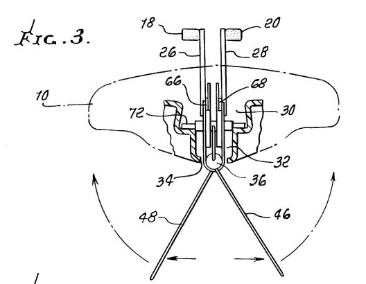
FIG. 4 is a Section taken along line 4--4 in FIG. 2.

FIG. 5 is a section taken along the line 5--5 in FIG. 4.

FIG. 6 is a section taken along the line 6--6 in FIG. 5.

FIG. 7 is a section taken along line 7--7 in FIG. 4.

FIG. 8 is a partial sectional, similar in location to FIG. 4, of an alternate embodiment of this invention.

FIG. 9 is a section taken along line 9--9 in FIG. 8.

One preferred embodiment is a pedaled kayak propelled by the "penguin" like action of two transversely oscillating flappers or sails. As the force on the pedals is increased, the less restrained end of the flapper or sail twists to assume a propeller like shape. As the flappers or sails oscillate, they change pitch or shape upon reaching the end of their arcuate movement, viz, when they simultaneously reverse direction of movement at the opposite ends of their arcuate pathway. This sail action is somewhat similar to what happens when tacking in a sailboat in that the sails exert, in both of their directions of movement, a forward thrust component.
Turning to the drawings in more detail, the drawings illustrate an embodiment of the invention in the form of a kayak having a generally elongated hull 10 made, for example, by rotomolding from a plastic such as polyethylene. The cockpit 12 has a seat 14 located such that the hip of the user is substantially fully below the upper deck 16 of the kayak. The cockpit 12 also contains a set of pedals 18 and 20 adapted to be pushed, first one and then the other, by the user's feet. The hull 10 is also provided with a rudder 22 and tiller 24.
The pedals 18 & 20 are operatively connected by pedal shafts 26 and 28, respectively, to the propulsion means which extends upwardly through two vertically disposed compartments 30 and 32 in the center of the bottom of hull 10, the upper compartment 30 being somewhat larger than the lower compartment 32. The bottom of the lower compartment 32 has an opening 34.
The drums 36 and 38 are rotatable about the fixed longitudinal steel shaft 40 which is carried in the lower compartment 32.
The rotatable drums 36 and 38 carry radially extending rigid masts 42 and 44, respectively. The masts project in a generally downwardly direction so that they always remain in the water and do not contact the underside of the hull. The masts support the sails or flappers 46 and 48, respectively, at their leading edges. Each of the sails is rotatable about its mast, so that the edge of the flapper opposite the leading edge can move from one side to the other with respect to the longitudinal center line of drums 36 and 38. This action results in both flappers exerting of forward force or push on the watercraft in both directions of transverse movement of the flappers, providing superior efficiency and speed. The extent of travel or movement of the trailing edges is limited by the adjustment provided by main sheet tensioners 50 and 52.
The sail or flapper support arm (mast) 42 is attached to the front of front drum and second Sail or Flapper support arm 44 is attached to the front of rear drum 38. At the rear of each sail or flapper, the main sheet tensioner connects to its respective drum and is adjustable in its reach or length to alter the tension in each of the sails or flappers 46 and 48.
The two drums 36 and 38 are normally in the water. The drums 36 and 38 are preferably made of an engineered plastic such as Delron. When the drums 36 and 38 rotate on the fixed longitudinal steel shaft 40, the inside of the Delron drums and the outside of the steel shaft form a bearing.
Typically, when the two sail or flapper support arms (masts) 42 and 44 are in the same plane with each other, the pedal shafts 26 and 28 are in the same plane with each other, although, of course, these two planes are perpendicular to each other. Perpendicularity is not important to the function of the invention.
FIGS. 1 to 7 show the most preferred embodiment of the means for providing propulsive force where cable connections are used exclusively. This embodiment has a total of five cables, three cables, 54, 56 & 58, at the front (front being in the direction of the bow of the kayak), and two cables, 60 and 62, at the back. The small pulley, 64, which is at the front with its cable 58 helps reduce excessive tension on the two rear cables.
Except for the cable 58 running over the small pulley, 64, the other 4 cables each run from one of the metal upper members, referred to as pedal support and cable guides, 66 and 68, each of which carry a pedal shaft, 26 and 28, to one of the Delron drums 36 or 38. Thus, two cables 54 and 60 run from one metal pedal support and cable guide 66 to front and rear Delron drums, 36 and 38, respectively. The other two cables 56 and 62 run from the second upper pedal support and cable guide 68 to the Delron drums 36 and 38. These cables have swaged ends which are countersunk into the Delron drums 36 and 38, as shown in FIG. 6. The flanges 70 on the pedal support and cable guides, 66 and 68, act as cable restrainers and serve to keep the cables in place over the guides.
The pedals and their shafts 26 and 28 are connected to pedal support and cable guides 66 and 68. The pedal support and cable guides 66 and 68 have Delron inserts so that pedal shafts and pedal support and cable guides can rotate back and forth on stationary transverse or cross shaft 72 which is fixably welded to the upper part of the coat hanger shaped support structure 74, the lower part of said support structure 74 carrying the longitudinal shaft 40, which, in turn, carries the two Delron drums 36 and 38 to which the sail or flapper arms (masts) are attached.
The holes 76 on each pedal shaft are provided with slidable pins which can be pulled in and out of the holes 78 which are arrayed across top of each of the metal pedal support and cable guides 66 and 68 to adjust for and accommodate different human leg lengths. This provides a very simple and effective adjustment mechanism to allow for different lengths of the human body. The pedals can be pinned in one of 5 locations to make adjustments.
The small front pulley rotates 64 on fixed shaft 80 which shaft is held by uprights 82 welded to the coat hanger shaped support structure 74 with screws. The small front pulley 64 preferably is polyethylene but Delron can be used. The nylon washers act as spacers to keep front pulley 64 in position.
Several cable systems can be used. A system which allows all four cables 54, 56, 60 and 62 to be adjusted independently by tightening or loosening of threaded ends 84 seems to work the best. Tuning the exact amount of flapper and pedal travel, and the size and stiffness of the flappers is a function of the watercraft characteristics and can be carried out by those skilled in the art.
FIGS. 8 and 9 show an alternate embodiment in which there is no front pulley and hence just 4 cables, three of which 86, 88, and 90, can be seen in FIGS. 8 and 9. These cables are connected to chains 94 which run over sprockets 96 and turn the metal drums (instead of Delron) 98. Except as noted, the embodiment of FIGS. 8 and 9 is the same in construction and operation as the first embodiment discussed hereinabove with respect to FIGS. 1 to 7.
The invention also includes the case where the cables are replaced by a gear train.
FIGS. 2, 3, 4, 5 & 9 show how the device is joined to the body of the kayak by T-bolts 100.
The present invention produces a lot of speed out of a kayak with little effort. The present invention provides watercraft which are more fun to use. The device is also highly utilitarian in that it can be easily removed from one watercraft and placed in another. The stability of the kayak is also improved with the flappers in the water.
It is usually not necessary to achieve more than one side-to-side cycle of the flappers through the arcuate pathway for every back and forth cycle of the pedals. When the ratio of the rotation of the flappers versus the cycle of the pedals is increased to a ratio of 3:1, the pedals move 14" while the flappers move through about 200 degrees of rotation. At this ratio, the resistance on the pedals is large and thus the cadence is low. Generally, the higher ratio permits the use of smaller flappers.
The flappers can be made in a fiberglass mold which makes a two sided fiberglass sail. The flexing and twisting characteristics are ideal. Similar sails could be vacuum formed in production. The flappers can also be made from flexible plastic or rubber. By using a flexible plastic, it is possible to eliminate the need for a separate mast. Instead, the flappers can be in the form of fins that can articulate or twist to form an angle of attack for providing forward thrust or propulsion.