Robert KOSTOFF
Gravity-Power Machine
Gravity-Power Machine
KeelyNet.com [09/06/07 ]
http://www.thepost.ca/webapp/sitepages/content.asp?contentid=679901&catname=Local%20News&classif=News%20Live
The Lindsay Post ( Canada )
Gravity
into Power
After about four years of planning and development through trial and error - including about a year-and-a-half creating the designs on paper - Bob Kostoff has reached his goal. He now owns the patent on the technology to prove it. The result was 'The Gravity Powered Machine.
' The self-sustaining engine provides as little as 10 foot-pounds of torque or as much as hundreds, Kostoff said, adding how its cost is less than half of a small wind turbine.
The machine - which only requires a little bit of start-up juice before it creates enough power to sustain itself - works much like a teeter-totter, using a series of sliding weights that, with the help of the earths gravitational pull, force the unit to continue spinning around in a circle.
Install a series of magnets in the unit and tens of thousands of watts of electricity can be produced, an amount that depends on the size of the actual machine.
“You can get off the hydro grid with one of these,” Kostoff told The Lindsay Post.
So far, about five of the units have been made. Once he got the concept down, he said he began fine-tuning the more cosmetic aspects of the machine, such as reducing noise.
“Once you figure it out, it's just about perfecting it,” he said.
The machines can be used in a variety of applications, Kostoff said, because they produce electricity at no cost.
For example, he said the units can be used to generate the power needed for electrolysis, a process that creates hydrogen, a “free fuel” that could be used to power your personal vehicle.
For more information on the gravity powered engine, or to see a video of it in action, visit www.newsourceofenergy.com. [ defunct website ]
This engine is a self sustaining gravity powered unit. It produces all the energy needed to run a generator large enough to provide power for all the hydro and heat needed for your home.
This patented system can be as small as producing 10 foot pounds of torque or as much as over 300 foot pounds of torque.
Each unit is approximately 8 feet by 4 feet by 6 feet tall and is totally enclosed for safely protection against moving parts.


https://www.youtube.com/watch?v=eT7oR_-l0qU
ENERGY
CONVERTER
CA2639107
CA2639107
A rotor rotates about a spindle and has one or more sliders which are movabl e between two stop points. An actuator is activated by pressurized fluid and causes th e slider or sliders to move back and forth between the stop points. The back and forth movement causes the spindle to rotate and the rotational energy of the spindle is harnessed to produce electricity.
FIELD OF THE INVENTION
This invention relates to an apparatus for converting one form of energy to another and more particularly to an apparatus for converting the energy from fluids under pressure to electrical energy.
BACKGROUND OF THE INVENTION
In mines and at construction sites, pressurized fluid is the usual source of energy for driving heavy machinery such as drills, power shovels and buckets. On farms, pressurized fluid is used in a wide variety of machines. It is used for example to raise and lower heavy machinery such as the cutting heads of combines, ploughs, mowers and the like.
Fluid under pressure is usually produced by compressors powered by gas, diesel fuel or gasoline. In most circumstances it is more economical to compress fluid on a continuous basis rather than periodically when it required. Where the pressurized fluid is produced continuously however, pressure tanks are required to store it until it is required for use. If the pressurized fluid is stored for relatively long periods of time, its pressure will dissipate and it will become unusable during those long periods and the fuel used to pressurize such fluid will be wasted. Accordingly, for the most efficient use of the fuel, the fluid should be used immediately after it is compressed.
I have invented an apparatus for converting the energy of pressurized fluid such as air and water to electrical energy. Unused pressurized fluid need not be stored in pressure tanks for long periods but may be converted to a form of energy which is a much more versatile than pressurized fluid. Since in most workplaces, there is a constant need for electricity, the electricity produced by my apparatus will be used immediately. There will be no need to store it and moreover, when it is used, there will a reduction in the use of electricity from other sources with resulting savings in the cost of electricity.
SUMMARY OF THE INVENTION
Briefly, the apparatus of my invention includes a spindle rotatable about a horizontal axis and a slider adapted to rotate about the axis. The slider is movable between two stop points on opposite sides of the axis. The apparatus also includes an actuator activated by pressurized fluid for causing the slider to move back and forth between the stop points. Also included are means for controlling the back and forth movement such as to cause the slider to rotate. Means is also included for harnessing the rotational energy of the spindle for the production of electricity.
DESCRIPTION OF THE DRAWINGS
The apparatus of the invention is described with reference to the accompanying drawings in which:
Figure 1 is a perspective view of the components of the apparatus;
Figure 2 is an exploded perspective of three components of the apparatus, namely a slider, an actuator and a rotor;
Figure 3 is a perspective view of an array of rollers on the rear face of the slider together with a groove in which the slider moves;
Figure 4 is a elevation of the slider and groove;
Figures 5 to 8 are elevations of the slider and an actuator which controls the movement of the slider. The Figures show the various positions of the slider as it completes one full revolution; Figure 9 is a simplified elevation of a rotor and sliders according to a second embodiment of the apparatus of the invention;
Figure 10 is an elevation of a portion of the rotor and slider illustrated in Figure 9; Figure 11 is a simplified elevation of each slider illustrated in Figure 9 in conjunction with the central portion of the rotor; and


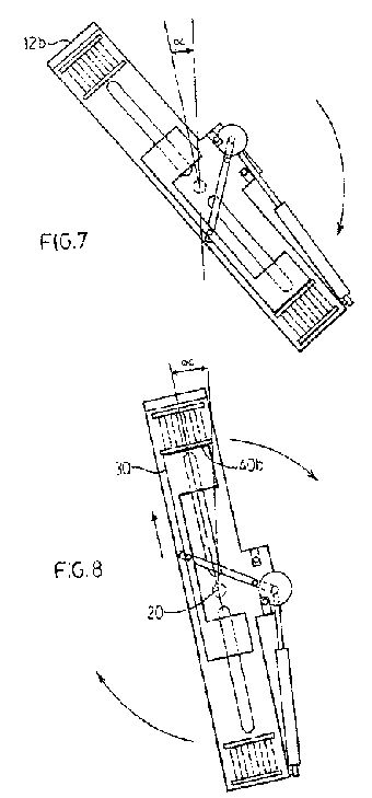


Figure 12 is an elevation of a rotor and sliders according to a third embodiment of the invention.
Figure 13 is a simplified elevation of a rotor and sliders according to a third embodiment of the apparatus of the invention.

Like reference characters refer to like parts throughout the description of the drawings.
DESCRIPTION OF PREFERRED EMBODIMENTS
With reference to Figure 1, the apparatus of the invention, generally 10, includes a rotor 12, a slider 14 and an actuator 16. The rotor is mounted to spindle 18 and revolves about a horizontal axis of rotation 20-20. The rotor has a longitudinal axis 12a-12a which passes through the axis of rotation.
A fluid such as oil is store in a tank 19 and when required, flows to a motor and pump, generally 20. The pump pressurizes the fluid and causes it to flow through an internal passageway in the spindle. The fluid flows from openings in the spindle to the actuator. The actuator is described below. The fluid may being either in the form of a gas such as air or a liquid such as oil or water.
The spindle is connected to speed accelerating apparatus, generally 22 for increasing the rate of rotation of the input shaft of a turbine generally 24. The apparatus is described below. The rate of rotation of the spindle is controlled by the combination of a governor, generally 26 and brake generally 28. The governor and brake are conventional and are well known to those familiar with the art.
With reference to Figure 2, the slider is formed of a single sheet of steel or other relatively heavy material and is composed of a pair of terminal plates 30, 32 interconnected by an elongated coupling 34. The two terminal plates are of equal weight and shape and are spaced apart an equal distance from the centre 34a of the coupling. The slider is symmetrical about the centre of the coupling.
With reference to Figures 1- 4, an array of rollers, generally 36 is formed on the under- side of each terminal plate 30,32. The rollers travel in elongated grooves 38a,b formed on the outer wall of the rotor.
The grooves are aligned with each other and each groove receives a separate array of rollers.
The grooves have aligned longitudinal axes 39 which lie on the longitudinal axis 12a-12a of the rotor so that the terminal plates travel in a direction parallel to the longitudinal axis.
A pair of spaced outer and inner end plates 40a, 40b, respectively is formed adjacent to one end of the rotor while outer and inner end plates 42a, 42b, respectively are formed at the opposite end of the rotor. Each outer end plate is attached to the rotor and is connected to a separate inner end plate by four coil springs 44. The inner end plate is not attached to the rotor but is free to move toward and away from the outer end plate. The springs bias the inner and outer end plates apart.
The slider is free to slide in grooves 38a,b whose ends define two stop points of travel. The coil springs cushion the force of impact of the slider on the inner end plates at each stop point. That force can be considerable when the rotor and slider are rotating rapidly.
With reference to Figures 1 and 2, the cylinder 16a of actuator 16 is pivotally attached to one end of the rotor. The ram 16b of the actuator is pivotally connected to one end of a rod 52. A pin 54 pivotally connects the centre of the rod to the ear 12a of the rotor. The other end of the rod is pivotally connected to coupling 34 at its centre 34a. The point of connection is on the axis of symmetry of the slider.
The actuator acts to cause the slider to move radially back and forth in grooves 38a,b. When the ram retracts from the position illustrated in Figure 2, rod 52 rotates clockwise about pin 54 with resulting radial movement of the slider to the left toward inner end plate 40b. When the ram extends, terminal plate 32 slides radially outward and into contact with inner end plate 42b. A conventional control 55 directs the operation of the actuator.
With reference to Figure 5, as previously indicated, rotor 12 revolves around a horizontal axis of rotation 20-20. The rotor revolves clockwise and its upper end 12a has passed the highest point of its travel during each revolution. The actuator has caused the terminal plate 32 of the slider to contact inner end plate 42b. The other terminal plate 30 is adjacent to the axis of rotation of the rotor and is at its greatest distance from the other stop point defined by inner end plate 40b.
The two terminal plates 30, 32 are of equal weight and they are spaced an equal distance from the axis of symmetry or centre of the slider. The upper plate 32, being farther from the axis of rotation 20-20 of the rotor, exerts a greater moment than the lower plate which is closer to the centre of rotation with resulting acceleration in the rate of clockwise rotation.
The moment or turning effect of terminal plate 32, being farther from the axis of rotation is greater than the moment of terminal plate 30. The preferred location of terminal plate 30 is not as shown in Figure 5 but rather at the axis of rotation where one half of its weight is on one side of the axis and the other half is on the other side. In that location, its moment will be approximately zero since one half of its weight will cause turning of the rotor in one direction while the other half will cause turning in the opposite direction. As a result, terminal plate 30 will have essentially no turning effect on the rotor while terminal plate 32, by contrast, will be the sole cause of turning disregarding of course the effect of inertia on the movement of the rotor.
The position of terminal plate 30 illustrated in Figure 5 is less desirable than that just described because it will exert a turning effect opposite to that of terminal plate 32. It will accordingly tend to work against the other terminal plate in causing the rotor to rotate.
Figure 12 described below shows the desirable location of terminal component 30 (num- bered 92b in Figure 12). In the embodiment illustrated in Figure 12, the two terminal components are not connected but the operation of the rotor is similar to that illustrated in Figure 5.
In Figure 6, end 12a which was previously the upper end of the rotor has now become the lower end. As the end approaches its lowest point in a revolution, terminal plate 32 continues to contact stop point 42b.
In Figure 7, end 12b of the rotor approaches its highest point and the ram of the actuator begins to retract thereby causing the slider to move upward. In Figure 8, the ram is fully retracted and terminal plate 30 contacts the stop point defined by inner end plate 40b. The momentum of the rotor carries it past the point at which its upper end 12b is vertically above the axis of rotation 20- 20. Once past that point, the moment produced by terminal plate 30 will cause the rate of rotation of the rotor to again accelerate.
With reference again to Figure 1, the speed accelerating apparatus 22 is composed by a driving pulley 60 which is attached by a spline to spindle 18 for rotation. A belt interconnects pulley 60 to first and second conventional arrays of belts and pulleys of unequal diameter, generally 62, 64 for increasing the rate of rotation of the output from the spindle. The output from the second array is connected by belt 66 to turbine 24. The turbine is of conventional construction and functions to generate electrical energy.
With reference to Figure 9, the rotor generally 70 is trihedral having three arms 72a,b and c. The angle between each arm and the adjacent arm on either side of it is 120 degrees. The arms have an elongated grooves 74 for receipt of sliders 76a,b and c. The sliders are movable between inward and outward stop points 78, 80 respectively. The stop points are defined by the inner and outer ends of the groove. It will be observed that the inner stop point is adjacent to the axis of rotation 82 of the rotor while the outer stop point is adjacent to the outer wall of the arm.
An actuator 90 is pivotally connected to an L-shaped support 92 attached to the outer wall of each arm. The ram 90a of the actuator is pivotally connected to a first link 94 which in turn is pivotally connected to a second link 96. the latter link being pivotally connected to the slider.
Sliders 76 operate in a way similar to slider 14 of the previous drawings. As the rotor revolves, each slider is drawn radially outward by the actuator to which it is attached as the arm reaches it uppermost position on the rotor. The actuator draws the slider radially inward when the slider reaches the lowermost position on the rotor.
With reference to Figure 10, the innermost position of slider 76c as arm 72c rotates about the axis of rotation 82 of the rotor is illustrated in broken lines. In that position, the slider is at the same elevation as the axis of rotation.
As the rotor completes each revolution, each slider will slide into and out of the in- nermost position once. Depending on the shape of the sliders, they may collide with and foul each other as they move into and out of this position. To avoid this, the walls of the grooves are constructed such that the slider in each groove travels in a path that traces out an imaginary disc but the discs of the three sliders are horizontally spaced apart from each other. Figure 11 illustrates the paths that the three sliders follow.
In Figure 11a, slider 76a is adjacent to the centre of rotor 12 as it revolves around axis 82. In Figure 11 b, slider 76b is spaced apart from the rotor by a space 80 which is slightly greater than the thickness of slider 76a and in Figure 11 c, slider 76c is spaced apart from the rotor by a space 82 which is slightly greater than the thickness of sliders 76a and 76b. The sliders being spaced apart in this manner will not contact each other as they move into and out of the innermost position on the rotor.
With reference to Figure 12 rotor 90 is similar to rotor 12 of Figure 1. The slider is how- ever different. Rotor 90 is provided with two sliders 92a,b which are not connected to each other. Each slider is of the same weight as the other and each travels on rollers in a separate groove 94a,b. The rollers and grooves are of the same construction as rollers 36 and grooves 38 in Figure 1. A separate actuator 96a,b activates each slider. Pivotally interconnected links 98, 100 interconnect the ram of each actuator and a separate slider. The operation of the rotor and sliders of Figure 12 is similar to the rotor and slider of Figure 1.
In Figure 12, slider 92 is at located at its outer stop point while slider 92b is at the inner stop point. Preferably the weight of slider 92b is evenly distributed on opposite sides of an imaginary line 100 which lies normal to the longitudinal axis 102a-102a of the rotor and which intersects the axis of rotation 104 of the rotor.
With reference to Figure 13, the rotor, generally 110, has a trihedral shape like the rotor of Figure 9. On each arm 112 of the rotor are two parallel lines of rollers 114 which define the path along which slider 116 travels. The path radiates outwardly from spindle 118 about which the rotor revolves and is oriented approximately 120 degrees apart from the paths of the other two sliders. Each slider is movable between radially inner and radially outer stop points at opposite ends of its travel. The slider is at its inner stop point when the end wall of slot 22 formed in the slider contacts spindle 118. The slider is at its outer stop point when the slider contacts end plate of arm 112.
An actuator 130 at the outer end of each arm causes the slider to move radially inward and outward in its respective path. The radial movement is controlled such that as each slider rotates toward an upper point 134 at which the slider is vertically above the spindle, the slider travels radially outwardly in its path. Conversely as each slider rotates toward a lower point 136 at which the slider is below the axis, the slider travels radially inward in its path.
Each actuator has a ram or piston rod 138 which is connected to a separate slider for imparting radial movement to the slider. The piston rod extends and retracts in a direction 140-140 which is collinear with the direction of radial movement of the slider. The direction of movement of the piston rod in this Figure is to be contrasted with the direction of movement of the piston rods in Figure 9. In the latter Figure, the piston rods extends and retracts in a direction which is spaced apart from the direction of radial movement of the sliders.