Lucjan LAGIEWKA
EPAR Shock Absorber
J. ZAGÓRSKI : RIDDLES OF THE MECHANICS
Videos
Euroinfrastructure : We had
Lagiewka’s bumper, will we see Ladiewka’s barrier?
Boleslaw Tabor : The Truth Like A
Poke In The Eye
US20070007780 --
Kinetic energy absorber, particularly for large mobile
objects
US20130033047 -- Collision
energy dissipating bum
WO2005121593 -- DEVICE
FOR TRANSFORMING KINETIC ENERGY
WO2014005656 -- Kinetic
stabilizer, in particular to compensate for changes in the
rotational speed of the driven equipment
WO2004028864 -- Method
& device for Vehicle Protection
WO2014005656 -- AN
ARRANGEMENT FOR PROTECTION OF HYDRAULIC ACTUATORS OF
UNDERGROUND SHIELD FROM DYNAMIC OVERLOAD...
WO2014009790 -- SUPPORT
UNIT OF INTERNAL COMBUSTION ENGINE
US2013284994 -- Road
Barrier And A Method For Manufacturing Thereof
WO2014006477 -- SHOCK
ABSORBING PLATFORM FOR UNLOADING CONTAINERS AT PORTS
From: "Henryk Mongia"
<heniumon@poczta.fm>
Subject: New Revolutionary Car Buffer patent
RIDDLES OF THE MECHANICS
JANUSZ ZAGÓRSKI
In November 1998 in the local stadium, in the presence of hundreds of people including representatives of media from the all country, together with his collaborators, Przemyslaw Lagiewka demonstrated the prototype of an unusual bumper. This showed what, was so unusual that continually acknowledged as impossible.
A small Fiat 126p, going 45 km per hour, was driven into a concrete wall. The bumper was not damaged. The driver wore no seatbelts. The inertial reaction, which should have thrown him onto the hood, did not ocur. The stopping distance was only 16 centimetres. Impossible? Yet hundreds of people in, and the stadium, and millions more on television. The use in all vehicles of the absorber of the energy, "Ecollision", can radically improve automobile safety.
Lagiewka says, "The technical idea behind my buffer can be used in very many practical solutions. Another invention which I showed experimentally, is the brake. Connected to the axis on a Mercedes, the car stopped in one-quarter of the distance usually required".
I had a short conversation with the manager of the Chair of the Mechanics and Energy-Devices AGH in Cracow, with the professor with Stanislaus Gumu??.:
- What you feels about the Lagiewka buffer ?
- This is a very original solution transforming the rectilinear motion into rotatory, thanks to which it succeeded to limit radically results of the collision of two bodies. This experiment recommends however to us, to research workers, many practical and theoretical problems.
- This means that one cannot give the binding scientific opinion?
- Unfortunately, not yet. We have from several months the small model of the vehicle Lagiewki with installed absorber of the energy, but are problems with an execution of measurement of physical parameters of this event. We want to make this with several methods. The thing is that the event lasts several milliseconds, and devices which we have at our disposal, are not disposed on such small times. Filming of the event little gives, because the alloy {stop}-the cage lasts too long [?]. Diodes, what we assemble on the model, to measure accelerations, do not light with such frequency, to catch sensitively the moment of the collision. We seek also suitable sensors of the power.
- Whether solution Lagiewki surrenders unsophisticatedly to explain aground well-known laws of physics?
- Some elements of this occurrence can not be situated in hitherto existing well-known interpretations of the laws of physics. As far as more easily one can to himself explain the lack of the damage of the car at the collision shown in the stadium in Kovars, insomuch more with difficulty interpret the fact that the driver, not having buttoned belts, did not fly through the windowpane. Doubtless this matter demands serious research. Lagiewki's inventions can find wide use in the future.
Lagiewski offers examples of uses for the invention. Thanks properly to constructed absorbers of the energy large ships can stop, not in 2-3 kilometres, as now, but in 100-200 metres. One can also build rescue-landings for people jumping during fires from high buildings. In Kovars, at the local firestation, on a 6-metre tower, tests were made by jumping onto the buffer...
All
mechanics is based on occurrences happening in collisions
only two bodies and from such experiments are derived
mathematical calculations. One did not trace, what happens,
when three bodies simultaneously crash. Lagiewska tested
3-boy collisions for 20 years. The results of his research
and experiments are shocking. And so at collisions of three
bodies one can control the situation, so that the energy two
crashing masses of greater bodies almost en bloc swim to the
third smaller mass. I had personally a possibility to
observe an experiment erected in the local House of the
Culture. The arrangement of three situated vehicles on
tracks provides a completely surprising occurrence. The
small vehicle, striking simultaneously into 3 the bodies,
the most of the energy gave back this to two standing from
one side to movement. Into the third place of the shock,
lying on the line of the movement of the vehicle, went least
the energy. The kinetic energy of the vehicle chose another
way than standing straight on the object. Basing on such
among other things experiments, Lagiewka builds on the new
mechanics. She throws rejects many hitherto existing notions
and uses new mathematical levellings. Polish
scientific-technical certers are examining Lagiewki's
inventions.


Project EPAR Lagiewka Bumper small test
https://www.youtube.com/watch?v=33Xy_Nnq1gE
Lucjan Lagiewka Geniusz z Kowar material archiwalny czesc 1/2
https://www.youtube.com/watch?v=z-h56N_A3rY
Lucjan Lagiewka walczy o patent - Cambridge kontra polski wynalazca
https://www.youtube.com/watch?v=JaFBXzrcPsM
Lucjan Lagiewka part 1
https://www.youtube.com/watch?v=dvEb9DndrKI
Lucjan Lagiewka part 2
https://www.youtube.com/watch?v=ea_F0GEx4GY
Lucjan Lagiewka part 3
https://www.youtube.com/watch?v=hLp1SPH1OUY
Lucjan Lagiewka part 4
https://www.youtube.com/watch?v=x-45k7TCIvg
Lucjan Lagiewka part 5
http://www.euroinfrastructure.eu/en/safety/byl-zderzak-lagiewki-bedzie-bariera-lagiewki/
Lagiewska’s bumper, a device that was supposed to disperse kinetic force of the impact was a phenomenon in the 90’s. But only a media phenomenon. However today, Lucjan Lagiewka is working on a road barrier. And he has almost 3mln PLN to use.
The case of “Lagiewka’s bumper” up to now evokes emotions. In the 90’s inventor – Lucjan Lagiewka – show a bumper that survived an impact with a Fiat 126p speeding 40km/h. The rule of its work is supposed to be based on taking over the kinetic energy impact and passing it on a circular movement special mechanism of rotors.
Up to today no car company hadn’t bought or used such bumper. Why? According to conspiracy theories – the project was blocked, because it would decrease the companies income. The inventor after years told the media that Military Intel was looking very closely into his project. According to others – because Lagiewska wasn’t completely able to scientifically explain what he has constructed. It’s confirmed by professor Stanislaw Gumula, ex science employee in AGH, according to who the process of work of this device cannot be explained with any known today physics laws.
The barrier will save and flash
Today Gumula is working with Lagiewka on EPAR project. Within it there are new unexplained techniques of kinetic energy dispersing designed. One of them is a road barrier which absorbs the impacts energy. As we can read on the projects website, it’s based on using a “system of mechanized rotor accumulators, intercepting and dispersing the impact energy”. According to the inventors such barrier not only will cause less damages of the car but also will reduce ostensible forces. She will also produce electricity thanks to the impact. “Thanks to using the intercepted impact energy in every barrier a self supplying light warning system will be possible to implement and an automatic alarm call to rescue forces” – praise the constructors.
EU project worth almost 3mln PLN
It sound a little bit like fantasy? It does. But the project received real cash. EPAR SP. z o. o. (place in Lódz) received support for research and development works regarding the barrier. 2 960 787 PLN was given from the Operational Programme – Innovative Economy for the project called “Safety road barriers a dynamic solution for absorbing the kinetic energy of an impact”.
The project is supported from EU funds since 2011 and those funds will end in December 2013. Will we see crash tests with the full scale barrier and a real life car accelerating to for example 80 kilometres per hour after that deadline? Not one knows. For now inventors convince, that their theory works by showing us a model with a ball...
EPAR project isn’t the only innovative project regarding road barriers. The Institute for examining roads and bridges has constructed an Active Intelligent Road and Bridge Barrier. Thanks to electronic structures equipped and modern construction solutions the level of impact absorption can be adjustet to vehicles of various mass ( a motorcar, a bus car, a lorry). The barrier is equipped in a system of video cameras, that registers incoming vehicles and is capable of forecasting the trajectory – so it can earlier assume whether the car will hit the barrier and measure their size. Electronic modules are, during that time, able to switch the construction on to receiving a particular type of energy. Thanks to it the barrier before the actual hit is prepared to get hit by a truck or a motorcar. The point of the solution is in fluid containers and hoses regulating pressure in them. Thanks to them the flexibility of the construction can be changed.
These devices work
Meantime there are projects already existing, that significantly reduce the danger for road users. During a hit with a car speeding 100 kilometres per hour you can’t avoid for example dents in the car. However, the driver has a big chance, that instead of a normal concrete lighting pillar, he will run into a pillar made out of a technology not absorbing the impact energy. Such crash tests took place this summer in Inowroclaw
Video :
http://www.euroinfrastructure.eu/bezpieczenstwo/komunikacja-spoleczna/co-zabija-co-ratuje-zobacz-zderzenia-z-urzadzeniami-na-drogach/
https://books.google.com/books?id=zaiJAwAAQBAJ&pg=PA71&lpg=PA71&dq=lagiewka+bumper&source=bl&ots=pzOtsx4YYh&sig=9H7uhE_p8ofA6PclonPSNrQqXwM&hl=en&sa=X&ved=0CD8Q6AEwBjgKahUKEwiYq-mxx-3HAhWF04AKHYSTCiI#v=onepage&q=lagiewka%20bumper&f=false
by
Boleslaw Tabor


US20070007780
Abstract -- The invention is related to a kinetic energy absorber, particularly useful for large mobile objects, applicable as a bumper in cars, elevators, rail-cars, quays and other objects susceptible to the effects of sudden collisions. It is characterized by the use of a rotor (4) connected to a bumper (6) through a multiplying gear (2).
Description
The invention is a kinetic energy absorber, particularly for large mobile objects, applicable as a bumper in cars, elevators, rail cars, quays and other objects susceptible to the effects of sudden collisions.
Kinetic energy absorbers known so far, which are used to protect cars against the effects of a potential collision with a fixed obstruction, are bumpers with a controlled crushing zone. In such cases, the absorbed kinetic energy is converted into energy required to deform car's structure.
Kinetic energy absorbers used in rail cars are helical dumper springs or elastomer filler inside the bumpers. In this solution, the absorbed energy is gradually transformed during a collision into potential energy of absorbers' elasticity and released afterwards leading to the rebound.
The primary feature of the invention (the kinetic energy absorber, applicable particularly to large mobile objects) is that it comprises a rotor connected to a bumper via multiplying gear.
The efficiency is increased when the multiplying gear is connected to the bumper by means of a toothed bar.
The effect is also intensified if the toothed bar and the bumper are separated with an elastic element.
Another advantage is achieved when the multiplying gear has the form of a toothed gear.
Thanks to the solutions proposed in this invention, it is possible to achieve almost total conversion of objects' translational energy into rotor's rotational energy.
When applied to various mobile objects the solution protects them from damage and keeps the passengers safe from injuries or, in extreme cases, even save lives. Items located inside the object are secured as well. Rebound from an obstruction has also been eliminated.
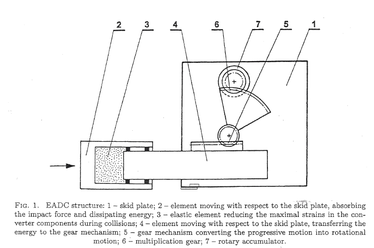
FIG. 1 represents a side view of the invention's sample embodiment and
FIG. 2 is a top view of the same.


The multiplying gear (2) meshed with the gear wheel (3) propelling the rotor (4) is installed on a frame (1) which is fixed to the potentially colliding object.
The multiplying gear (2) is meshed with the toothed bar (5) fixed to the frame in such a way that it is free to slide along (1). The toothed bar (5) is equipped with a bumper at least from one side.
In some variations of the invention, the toothed bar (5) is connected to a bumper through an elastic element (7). In other variations the toothed bar is equipped with a bumper (6) on both sides.
Yet in other variations, the multiplying gear (2) is propelled by a system of pulling rods.
An object in a translational motion has kinetic energy which is used for deformation of the object during a collision with a fixed rigid obstacle.
In the case of the presented solution, during obstacle's (not shown in the figure) interaction with the bumper (6), object's kinetic energy is transmitted to the toothed bar (5) and then through the multiplying gear (2) to the rotor (4) which makes it rotate.
In the course of this process, the kinetic energy of object's translational motion is converted into the rotational energy of the rotor.
In order to avoid damaging the multiplying gear (2), an elastic element (7) should be mounted between the bumper and the toothed bar (5).
During tests, the presented absorber was used as a car bumper. Normally in the case of a collision with another car or a fixed; rigid obstacle, such as a tree or a wall, the kinetic energy of a car is converted into deformation energy of the car's crashing zone.
The absorber used makes it possible to slow the vehicle down to zero without any structural deformation due to its quick energy conversion rate.
The vehicle alone contributes only partially to the total kinetic energy before the collision as the rest of it comes from the passengers and their luggage.
In another application, the absorber can be installed under elevator's floor or at the bottom of the shaft. In the case of emergency, such as snapped lifting rope, the kinetic energy of the falling cabin and its passengers, should be transformed into rotational energy of the rotor (4) without exerting any substantial force on the falling object.
The absorber can also be installed in rail cars' bumpers. When rail cars collide, being linked to the train, their kinetic energy is transformed into rotational energy of a rotor (4). It protects the cars and their load form damage. The protection works with a traveling train as well, eliminating all negative effects of kinetic forces.
Yet another possible application is to install the absorbers in the quays. It should eliminate the excessive forces that ships' sides exert on quay's walls, protecting thus the cargo from moving inside the hold.
Abstract -- A bumper has a ram (1) cooperating by a pressure fluid chamber (5) with a collision energy dissipating unit (11), in which kinetic energy of progressive motion is converted into kinetic energy of rotary motion. The pressure fluid chamber (5) is made as an angle fluid splitter (4) comprising an input cylinder (3) co-operating with a piston (2) of the ram (1) and at least two output cylinders (6, 7) angularly deviated from an axis (20) of the input cylinder (3), said output cylinders co-operating with pistons (9), the piston rods (10) of which are linked with the energy dissipating units (11) driving spinning masses (15).
Description
This invention concerns a collision energy dissipating bumper in which kinetic energy of progressive motion is converted into kinetic energy of rotary motion. This solution is to be used especially in motorized vehicles as well as in other objects exposed to unexpected collisions.
From patent application WO2004028864 a device for protecting vehicles against collision effects is known in which kinetic energy suddenly created by a collision is converted into kinetic energy of spinning masses.
According to this known solution vehicles are protected against collision effects by a bumper comprising a toothed bar co-operating with transmissions driving spinning masses. An elastic element is situated between a ram and the toothed bar in order to decrease an impact during an early phase of a collision.
A device for converting kinetic energy is also known from specification WO2005121593, said device comprising a ram co-operating by a pressure fluid chamber with a unit dissipating energy created by a collision. This unit is formed as a rack forcing the rotary motion of spinning masses so as to smoothly change kinetic energy of progressive motion created as a result of the collision into kinetic energy of rotary motion.
The object of this invention is to increase the effectiveness of impact energy dissipation.
A bumper according to the invention comprises a ram co-operating through a pressure fluid chamber with an impact energy dissipating unit, in which kinetic energy of progressive motion is converted into kinetic energy of rotary motion. This solution is characterized in that the pressure fluid chamber is made as an angle fluid splitter comprising an input cylinder co-operating with a piston of the ram and at least two output cylinders directed at an angle from an axis of the input cylinder, the said output cylinders co-operating with pistons whose rods are connected with the energy dissipating units driving spinning masses.
In an advantageous solution axes of the output cylinders are deviated at an angle of 90° in relation to the axis of the input cylinder.
In another advantageous solution the angle fluid splitter comprises three output cylinders, two outermost of which are deviated at an angle of 90° in relation to an axis of the input cylinder, and the middle output cylinder is situated along the axis of the input cylinder.
In a further advantageous solution the angle fluid splitter comprises four output cylinders. Two outermost output cylinders are deviated at an angle of 90° from the axis of the input cylinder, and two longitudinal output cylinders are parallel to the axis of the input cylinder.
In an advantageous solution the energy dissipating unit driving the spinning masses is made as a rack transmission in which a rack drives a spinning mass by means of a transmission increasing the rotational speed.
By using the pressure fluid chamber made as an angle fluid splitter with its input cylinder co-operating with a piston of the ram, and with at least two output cylinders angularly deviated from the axis of the input cylinder, a greater collision energy dissipation is achieved, that means a greater part of a vehicle energy is taken over by the bumper.
A particularly advantageous effect of a mutual elimination of collision forces is achieved when using the angle splitter in which axes of output cylinders are deviated at an angle of 90° in relation to the axis of the input cylinder.
An embodiment of the invention is shown in the drawing in which
FIG. 1 is an axial section of the bumper having two output cylinders,
FIG. 2 is an axial section of the bumper having three output cylinders,
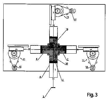
FIG. 3 is an axial section of the bumper having three output cylinders during a collision, and
FIG. 4 is an axial section of the bumper having four output cylinders.


In the embodiment illustrated in FIG. 1 a ram 1 is connected with a piston 2 located in an input cylinder 3 of an angle fluid splitter 4 in the form of a three-way pipe creating a pressure fluid chamber 5. The angle fluid splitter 4 has moreover two output cylinders 6, 7 with their axes 8 deviated from an axis of the input cylinder 3 at an angle of 90°. A piston 9 connected to a push rod 10 is located in each of the output cylinders 6, 7, the said push rods 10 of each piston located in the output cylinders 6, 7 are coupled with an energy dissipating unit 11. The energy dissipating unit 11 used in this embodiment during a collision changes kinetic energy of progressive motion into kinetic energy of rotary motion. The energy dissipating unit 11 consists of a rack 12 co-operating with a gear 13 connected with a transmission 14 increasing the rotation speed, the said transmission 14 driving spinning masses 15 having a determined moment of inertia.
Cooperating parts of the bumper are fastened inside the vehicle construction or inside the vehicle bumper in such a way that the ram 1 is located in an area of the greatest risk of a collision, and parts participating in energy taking over are located in an area protected against an excessive deformation. In the embodiment illustrated in FIG. 1 the bumper is fastened on a body plate 16, and bumper parts involved in energy takeover are fastened to said plate in such a way as to provide their proper co-operation during a collision. The angle fluid splitter 4, sliding guides 18 for the racks 12 and axles of the transmissions 14 increasing the rotation speed are fastened to the body plate 16.
FIG. 2 shows a bumper comprising an angle fluid splitter in which the piston 2 of the ram 1 is located in the input cylinder 3, and three output cylinders 6, 7, 19 are arranged in equal angle intervals, whereas axes of two outermost output cylinders 6, 7 are deviated from an axis 20 of the input cylinder 3 at an angle of 90°, and a single middle output cylinder 19 is situated along the axis 20 of the input cylinder 3. While the device is acting, the pistons 9 sliding in the output cylinders 6, 7, 19 are driving the spinning masses 15 in the energy dissipating units 11.
FIG. 3 shows a bumper comprising an angle fluid splitter with three output cylinders 6, 7, 19 while working as a result of a collision. While this device is working, the pistons 9 sliding in the output cylinders 6, 7, 19 drive the spinning masses 15 in the energy dissipating units 11. The arrows near the moving elements show the direction of their shift or rotation.
In another embodiment illustrated in FIG. 4 the angle fluid splitter has four output cylinders 6, 7, 21, 22. The two outermost output cylinders 6, 7 are deviated from the axis 20 of the input cylinder 3 at an angle of 90°, and two longitudinal output cylinders 21, 22 are located on both sides of the axis 20 of the input cylinder 3 parallel to said axis. The spinning masses 15 of each of the said four energy dissipating units 11 are driven in the same way as in embodiments illustrated in FIGS. 1-3.
According to the invention and as it is illustrated in FIG. 1 collision energy received by the ram 1 of the bumper as kinetic energy of progressive motion is transmitted by a fluid shock absorber, made as a pressure fluid chamber 5, to the collision energy dissipating unit 11, in which kinetic energy of progressive motion is converted into kinetic energy of rotation motion by driving the spinning masses 15.
Kinetic energy of progressive motion received by the ram 1 is divided in the pressure fluid chamber 5 of the fluid shock absorber into at least two directions. In the embodiments illustrated in FIG. 1-FIG. 4 collision energy by a thrust of a pressured agent inside the pressure fluid chamber is divided respectively into two, three and four directions. The fluid moving under the pressure is forced into the output cylinders in which moving pistons drive spinning masses. In the embodiments the spinning masses 15 are driven by means of a rack transmission coupled with the transmission 14 increasing the rotation speed.
Each kind of a transmission may be used as the transmission 14 increasing the rotation speed. Especially one may use belt transmissions, chain transmissions as well as all kinds of toothed transmissions.
The strength of parts participating in receiving and transmitting collision energy is selected depending on a mass of a vehicle in which the bumper according to the invention is to be used and depending on a speed reached by that vehicle, thus depending on parameters characteristic for kinetic energy of progressive motion reached by that vehicle. In a case the bumper is used for protecting objects exposed to the impact of outer forces, strength parameters of bumper parts are selected based on the most probable values of energy received by the protected object.
The cushion ability of the fluid splitter 4 is selected depending on the use of the bumper according to the invention. To achieve this aim, an inner space of the fluid splitter 4 closed between its pistons is filled with fluid of suitable compressibility and being under a suitable initial pressure. When using a gas, the maximum protection of mechanical transmissions driving spinning masses against an impact load is achieved, whereas when using a liquid characterized by a low compressibility, an initial load of mechanical transmissions is greater, but at the same time the efficiency of converting kinetic energy of progressive motion into kinetic energy of rotation motion is better. A suitable compromise between minimizing the impact load of parts in mechanical transmissions and obtaining suitable effectiveness of energy conversion is achieved by filling the space inside the fluid splitter 4 with a liquid-gas mixture or with a suitably chosen material undergoing the plastic deformation, for example an elastomer.
In order to obtain the correct bumper activity, the spinning masses 15 after achieving the maximum rotation speed during collision are disengaged from co-operation with driving elements transmitting energy to them
Abstract --- The invention relates to a device for transforming kinetic energy, comprising a first body (2), which may be displaced from a starting position to an end position as a result of an external force (F) and at least one second body (7) mounted such as to rotate, coupled to the first body (2), whereby a longitudinal displacement of the first body (2) drives the second body (7) in rotation, such that the first body is braked.
Linear
moving bodies such as vehicles, vessels, aircraft, boats,
or the like have, in particular at high speeds on a high
degree of kinetic energy, which is mostly converted in an
impact on stationary objects into deformation energy.
In
vehicles, for example, selective deformation areas are
provided in the front section of the vehicle to initiate
an impact energy without damage to the passenger
compartment in the chassis.
However,
the conversion of kinetic energy into deformation energy
has the decisive disadvantage that the vehicle or the like
is sustainably destroyed.
Furthermore,
there is at said deformation energy conversion in most
cases is a disadvantage that it is only a limited
deformation distance is available.
For
braking particular linearly moving bodies conventionally
numerous devices are known, which are called
Viskosebremse.
A
linear movement of the body is transferred to a rotating
in a viscose pinion via a rack or the like.
An
increasing rotational speed of the pinion is reflected in
a greater braking torque, whereby the body is slowed down
accordingly.
Such
Viskosebremsen are known for example from DE 197 29 900
C1, DE 28 11 020, DE 296 21 043 or DE 295 18 173 is known.
However,
these conventional Viskosebremsen subject to the
disadvantage that they are only suitable for braking at
low speeds.
WO
03/005142 A1 describes an apparatus for controlling
mechanical forces, in which the relative acceleration
between two connection points is determined either by a
flywheel gear or a differential piston mechanism.
The
invention is based on the object to provide a device for
transforming kinetic energy, which is suitable with simple
means for braking high linear velocities.
This
object is achieved by a device having the features of
claim 1 and by an apparatus having the features of claim
19.
Furthermore,
the object is achieved by a system having the features of
claim 31.
Advantageous
developments of the invention are defined in the dependent
claims.
An
inventive device for transforming kinetic energy comprises
a first body to a final position can be moved
longitudinally in a row of an external force from a
starting position, and at least a second body, which is
mounted rotatably mounted on the device.
The
second body is coupled to the first body, wherein a
longitudinal displacement of the first body leads to a
rotation of the second body, so that the longitudinal
movement of the first body is braked.
The
kinetic energy, which is associated with the movement of
the first body is thus converted by means of said coupling
advantageous in a rotational energy of the second body.
In
an advantageous embodiment of the invention, the coupling
between the first body and the second body in a
transmission ratio takes place.
A
longitudinal displacement of the first body thus leads to
a relatively high rotational speed of the second body.
According
to the invention can be ratios of 1:50 achieve, without
causing damage to the bearings or the like in the
apparatus.
In
an advantageous embodiment of the invention, the first
body is connected to a rack member.
The
rack member is expediently, in mesh with a transmission
gear, which may comprise a plurality of gear stages.
The
second body is driven by the reduction gear suitable
excess.
In
an advantageous embodiment of the invention the second
body is formed as a rod element which is mounted in
rotation around its center.
Thus
rotate two approximately equal to long leg of the rod
member to the rotational axis of the rod member.
At
the opposite ends of the rod member each mass body can be
fixed, the increase in the offset rotary mass
advantageous.
To
count the response of the rod element to facilitate from a
standstill, a centrifugal weight can be provided, which is
arranged longitudinally displaceable manner along the rod
member.
During
a rotation of the rod member along the flyweight of the
rod member is radially outward, that is, moved away from
the axis of rotation.
Thus
arises with increasing speed of the rod elements or for
further outward moving flyweight advantageously a greater
moment of inertia of the rod element.
Here,
the centrifugal weight can advantageously be biased by a
spring device in the direction of the rotation axis of the
rod member, whereby the Fliehelement is held in a preset
position.
With
increasing angular velocity of the rod member the
flyweight against the spring force is outward, ie away
down from the axis of rotation, which has an advantageous
moment of inertia is reflected in the greater inertia.
To
avoid adverse imbalances or like two centrifugal can at
the bar element on both sides of the axis of rotation to
provide weights that longitudinal and explained along the
rod member are slidably received.
In
an advantageous embodiment, the coupling between the first
body and the second body by a strap means done.
The
strap means may be attached by means of a tangent cam on
the second body.
If
a tensile force is applied to the strap means in
consequence of the shift of the first body, the tangent
cam and thus the second body is in a Rotation offset.
Advantageously,
the second body at the tangent cam is secured by means of
a freewheel, so that the second body to an initial driving
by the tangent cam further can rotate freely.
In
order to exert a tensile force upon movement of the first
body to the strap means, a so-called finger device is
fitted with finger members to the first body.
In
the initial position of the first body, the finger means
is opposite to a recording block to which are
complementary to the finger elements of the finger means
web elements.
The
strap means extending between the finger means and the
receiving block.
If
the first body enters into its final position, the finger
elements engage with the web members and assume the strap
means with.
As
a result, a tensile force is exerted on the tangent cam
and thereby enables the second body to rotate about the
strap means.
For
a particularly simple mounting of the strap means between
the finger means and the receiving block on both sides of
the receiving block two second bodies are arranged,
wherein the strap means is stretched between the cams of
the respective tangent second body.
Thus,
in one engaging-Get the finger means are synchronously
displaced with the receiving block both second body
through the strap means in rotation and braked the linear
movement of the first body accordingly.
In
an advantageous embodiment of the invention, the rack
member, which is connected to the first body in engagement
with a gear on which another tangent cam is mounted.
The
strap means is properly tensioned between the two tangent
cam, so that rotation of the gear wheel applies a tensile
force as a result of longitudinal displacement of the rack
member to the strap means and enables the second body to
rotate.
Such
an embodiment, in which only a second body is driven by
the belt means, characterized by smaller installation
dimensions.
The
second body is advantageously designed as a flywheel,
which supports converting the kinetic energy into
rotational energy.
In
addition, brake elements can be provided which can be
brought into contact with the centrifugal mass, so that
the rotating flywheel can be braked by suitable pitching
of braking elements on the flywheel.
In
an advantageous embodiment of the invention, the coupling
between the first body and the second body is lifted at
the end position of the first body.
This
results in that the second body is able to rotate after
the conversion of kinetic energy into rotational energy
more freely without a coupling to the first body restricts
the rotation of the second body.
In
an advantageous embodiment of the invention, the coupling
between the first body and the second body is subdued.
This
can be, for example, a gas compression spring means or the
like reach, wherein the rack member having a free end
which can serve as a piston rod which is slidably guided
within a gas-filled container.
For
transforming kinetic energy of the other an inventive
device is provided, comprising a body which can be moved
longitudinally in a row of an external force, a filled
with a fluid container and a body connected to the piston.
The
piston is guided displaceably inside the container between
an initial position and a final position, wherein the
container has a maximum fluid filling in the starting
position of the piston.
During
a longitudinal displacement of the body, the fluid is
displaced by the pistons and discharged from the
container, so that the longitudinal movement of the body
is suitably braked.
In
an advantageous embodiment of the invention, the container
has at least one opening for discharging the fluid.
To
ensure a uniform discharge of the fluid from the container
out, a plurality of openings practical, which may be
mutually provided evenly spaced in the enclosure.
A
piston surface of the piston acting on the fluid, a gear
ratio determined in relation to an opening cross section
of the opening i.
By
analogy with a gear ratio of a mechanical gear determines
the gear ratio i in the fluid solution, the extent to
which the kinetic energy of linear motion of the body is
transformed or braked.
An
essential aspect of the inventive device is that the
energy transformation takes place via a so-called energy
transferring mass in the fluid solution that is determined
by dividing the mass of the device to the square of the
product of the transmission ratio i.
Accordingly,
the energy transformation per length displacement of the
piston takes place via a so-called energy-transmitting
volume which is determined by dividing the energy transfer
through the mass density of the fluid.
It
follows that the inventive energy transformation takes
place exclusively on the mass of the body, wherein a speed
of the device remains at a stationary obstacle out of
consideration during an impact.
In
an advantageous embodiment of the invention is an end of
the container, opposite the movable piston, substantially
parallel to the piston surface, wherein the at least one
opening formed in the container adjacent to the end face.
In
this way a uniform escape of fluid from the container at
the maximum displacement of the fluid is ensured by the
piston in the container.
In
particular for the transformation of very high kinetic
energies, ie with very fast moving body, it is
advantageous if the front side of the container, which is
opposed to the movable piston having a wedge shape.
Here,
the opening in the container, from which the fluid in the
sequence
Piston
movement is removed, is formed as an annular gap extending
between the wedge shape and a container wall.
The
wedge shape of the end face advantageously prevents
leakage of turbulent flows of fluids and ensures a removal
from the container with the desired damping ungswirkung.
In
the latter embodiment are certi- ficate to the inner
surface of the containers in a plane in front of the wedge
tip and orthogonal to the intended direction of movement
of the piston stop elements that define the end position
of the piston.
If
the piston is in its final position comes into contact
with the stop elements, impingement of the piston at the
wedge tip is not possible to give an adverse destruction
of the wedge tip can be prevented.
Wherein
said fluid may be a gas, a liquid, or solid particles of
microscopic dimensions.
If
the gas is placed inside the container under pressure, or
alternatively, when using a liquid, the opening in the
container is expediently closed by a diaphragm, a valve or
the like to an output force of the pressurized gas or
liquid To prevent the initial position of the piston.
In
a piston displacement and a corresponding displacement of
the fluid in the container, the membrane, the valve, or
the like is opened in order to ensure the said discharge
of the fluid from the container out.
In
an advantageous embodiment of the invention, the device
with the rotating body and the second device may be
combined with the fluid container to one system, the
respective devices are arranged in series and connected to
each other.
In
this case, preferably a longitudinal displacement of the
body due to the external force begins sequentially.
Through
such a series connection of individual devices can be
advantageously a very large transmission ratio and thus an
extremely high dissipation of kinetic energy to achieve.
Further
advantages and embodiments of the invention will be
apparent from the description and the accompanying
drawings.
It
is understood that the features mentioned above and those
yet to be explained not only in the respectively specified
function, but also in other combinations or alone, without
departing from the scope of the present invention.
The
invention is diagrammatically illustrated by way of
example in the drawings and will be described below with
reference to the drawings.
In
the drawings: Figure 1 is a simplified illustration of a
principle according to the invention.
Device,
Fig. 1a shows a simplified illustration of the inventive
principle
Device
in a further embodiment, Fig. 1 b is a modification of
the apparatus of Fig. 1a, Figure 2 is a simplified
illustration of the principle according to the invention
Device
in a further embodiment, Fig. 3 shows a schematic
representation of the inventive device in a further
embodiment,
Fig.
4a shows a schematic representation of the inventive
device in a further embodiment,
Fig.
4b is a plan view of the embodiment of Fig. 4a,
Fig.
5 a schematic cross-sectional view of the inventive
advantages direction in a further embodiment, Fig. 5a,
the operating principle of the apparatus of
Fig.
6 shows a schematic cross-sectional view of the
inventive advantages direction in a further embodiment,
Fig. 7 is a vehicle, at the front, the device of
the invention in Region is attached,
Fig.
8 is a time-distance diagram for the inventive apparatus
in a frontal impact of the vehicle shown in Fig. 7,
Fig.
9 shows a speed-time diagram for a front impact in the
Shown Fig. 7 the vehicle,
Figure
10, an acceleration-time diagram,
Fig.
11, an acceleration-time diagram,
Fig.12
is a graph of impact force versus time,
Fig.
13 is a speed-time diagram for a rotary the flywheel
after impact,
Fig.
14 is a power-time diagram,
Fig.
15 is a diagram for the impact force as a function of
time,
Fig.
16, an acceleration-time diagram,
Fig.
17 is a diagram of accelerations as a function of time
for one Impact with / without the inventive
device,
Fig.
18 is a diagram for the impact force as a function of
time for a Impact with / without the inventive
device,
Fig.
19 is a diagram for the impact force as a function of
time with a variable transmission ratio for a device
according to Fig. 5 and 6, and
Fig.
20 is a diagram for the impact force as a function of
time with a variable transmission ratio for a device
according to Fig. 5 and 6.


In
Fig. 1 a first embodiment of the inventive device is
illustrated in principle simplified.
The
device comprises a base plate 1.
A
first body 2 in the form of a cylinder is arranged
longitudinally displaceably with respect to the base plate
1.
The
cylinder 2 is filled with air 3, and closed at its open
end by a piston rod 4, which has a rack 4a.
On
the piston rod 4 are provided sealing elements in the form
of 0Ringen 4b which are in contact with an inner wall of
the cylinder 2, and prevent leakage of air 3 from the
cylinder 2.
On
the base plate 1, a gear wheel segment 5 is rotatably
mounted, which is attached thereto via a gear 6 with the
rack gear 4a engage.
Adjacent
to the gear segment 6, a second body 7 is rotatably
mounted in the form of a flywheel.
Another
gear 8 is fixed to the flywheel 7 and meshes with the gear
segment. 5
A
translational displacement of the first body 2 is realized
by the gears 6,8 and the gear segment 5 in a rotation of
the flywheel. 7
The
device shown in Fig. 1 can be used advantageously in a
vehicle shown in Fig. 7.
The
attachment of the device to the vehicle is carried out
such that the base plate is fastened via fastening means
1a to the vehicle chassis, wherein the cylinder 2 is
connected to a front bumper of the vehicle.
Thus,
a force acting in a frontal impact of the vehicle on the
front bumper, passed down through the cylinder 2 to the
piston rod 4 and as explained converted into a rotation of
the flywheel. 7
The
gear stage consisting of the gears 6 and 8 and the gear
segment 5 is such that the meshing elements are separated
from each other when the flywheel is 7 to rotate.
Thus,
another free rotation of the flywheel 7 is ensured if the
linear impact energy is converted into rotational energy.
With
the apparatus shown in FIG. 1, ratios of up to 1:50 can be
obtained.
Thus,
in a usable rack length of 20 cm, for example, occurs in
the same flow power that would otherwise be achieved with
a linear braking distance of 10 m.
Overloading
of the components is suitably achieved by the pneumatic
damping, which is given by the air-filled cylinder 2 and
3, the piston rod 4.
In
Fig. 1a, the inventive device, in which a flywheel driven
by a translatory displacement in a further agreed
simplified embodiment shown.
The
gear stage consists essentially of the rack 4a, a meshing
with the rack 4a gear 6 'which is hollow, and the flywheel
7 positioned within the gear 6' is arranged to rotate.
The
gear stage according to the embodiment of FIG. 1 is
designed as a planetary gear, the gear ratio determined by
the respective diameters of the gear 6 'and the flywheel 7
positioned within the gear 6' is provided with an internal
toothing of the gear 6 'is engaged rotates and ,
The
cross-sectional view of Fig. 1b shows the embodiment of
FIG. 1a in a further development, in which the flywheel 7
can be braked by braking body 9.
The
brake body 9 are arranged on opposite sides of the
flywheel 7 and can be by means of a press contact force
respectively against the rotating flywheel 7 so that the
rotational energy is converted into frictional heat.
In
FIG. 2, the inventive device is shown in a further
embodiment.
The
same components as compared to the Fig. 1 herein are
provided with the same reference numerals.
On
the base plate 1, a gear 11 is rotatably mounted, on the
toothed wheel 11, a rod member 12 is attached.
The
gear 11 meshes with the attached to the piston rod 4 the
rack 4a.
Accordingly,
a translational displacement of the first body 2 via the
piston rod 4, the rack 4a and the gear 11 to a rotation of
the rod member 12.
At
the opposite ends of the rod member 12 additional mass
body 13 are attached, the 12 about its rotational axis 12a
increase the moment of inertia of the rod member is
advantageous.
Further
centrifugal weights 14 are provided on the rod element 12
which are slidable along the rod member 12.
The
flyweights 14 may be designed as a solid ball having a
through-hole whose inner diameter is suitably adapted to
the outer diameter of the rod member 12 to provide a
low-friction sliding along the rod member 12.
In
the shown on the right portion of the rod member 12 is
indicated by reference numeral 15 is a spiral spring, with
the flyweight 13 can be biased to an initial position.
If
the rod member 12 is rotated, the centrifugal weight 14
moves radially against the force of the coil spring 15 to
the outside.
By
means of the flyweights 14 in a biased position, which is
located near an axis of rotation 12a of the rod element
results, a favorable response of the rod member 12, its
moment of inertia with increasing angular velocity
increases by the wandering outwards flyweights 14th
By
a suitable selection of the diameter of the gear 11 and
optionally further gear stages between the rack 4 and the
rod member 12 can be achieved ratios of up to 1:50 and in
the device shown in Fig. 2.
In
Fig. 3 a further embodiment of the inventive device is
shown.
Here,
on the base plate 1, two second body 20 are rotatably
mounted in the form of rotating masses.
At
the respective inertias so-called tangent cam 21 are
mounted, between which a strap means 22 is tensioned.
The
strap means 22 is wound on an outer periphery of the
respective tangent cam 21st
The
strap means 22 extends between a finger 23 and a receiving
block 24th
The
finger means 23 is connected via a piston rod 4 with the
first body 2, and the receiving block 24 is fixedly
mounted to the base plate 1.
The
finger means 23 has a plurality of finger members 23a.
Complementary
to these finger elements 23a includes the mounting block
24a 24 web elements.
At
the free ends of the finger elements of the web elements
23a and 24a each roller elements 25 are provided, which
have a freely rotatable roller.
The
finger means 23 and the receiving block 24 serve to exert
a pulling force to the strap means 22, when the first body
2 is moved due to an external force F in the direction of
the base plate. 1
In
the case of a displacement of the finger means 23 in the
direction of the receiving block 24, the finger members
23a enter into engagement with the web elements 24a,
wherein the strap means 22 is thereby stretched over the
respective roller elements 25.
As
a result, the two tangent cam 21 and thus the centrifugal
masses 20 are rotated.
The
characteristic shape of the outer circumference of the
tangent cam 21, a large gear ratio is advantageously
achieved, ie a large rotational speed of the flywheel
masses 20, when the strap means 22 is engaging Get the
finger means 23 is pulled by the the receiving block 24
respectively inward.
A
suitable dimension of the tangent cam 21 also in the
embodiment of FIG. 3, a desired transmission ratio safely.
Since
the strap means in the tensioned initial state (shown in
Fig. 3) initially represents a resistance for the moving
in the direction of the receiving block 24 finger means
22, 23 allows the translational motion of the body 2 on
which the finger means 23 is mounted, brake as desired ,
The
further embodiment shown in Figs. 4a and 4b the inventive
device also comprises a belt device with which a flywheel
is driven.
To
the body 2 is a damping device, as explained, a piston rod
4 is attached, which has a rack 4a.
4a
with the rack meshes with a rotatably mounted to the base
plate 1 gear 30, to which a tangent cam 31 is fixed.
Opposite
to the gear 30, a second body 32 is rotatably mounted in
the form of a flywheel on the base plate 1, on which in
turn a tangent cam 33 is fixed.
Between
the tangent cam 31 and the tangent cam 33 a strap means 34
is tensioned.
If
a translational movement of the second body or the piston
rod 4, the gear 30 is set in rotation, the strap means 34
is wound 31 tennocke on the tangent, wherein the strap
means 34 applies a tensile force to the fixed to the
flywheel 32 tangent cam 33rd
As
a result, by the flywheel 32 is rotated by movement of the
second body in the direction of the base plate as a result
of an external force in rotation, which produces 1
analogous to the embodiment of FIG. Explained the energy
transformation.
In
the embodiments of Figs. 3 and 4 the tangent cam 21,33 are
conveniently attached via a freewheel to the flywheel
masses 20,32, such that rotation of the tangent cam
coupled only in one direction at the flywheel masses.
Consequently,
the centrifugal masses 20, 32 are free, that is rotate
independently of the corresponding tangent cam on, after
they have been displaced by the tangent cam in rotation.
In
FIGS. 5,5a and 6, the inventive device is shown in a
fundamentally different embodiment, namely using a fluid
to transform the kinetic energy.
On
the base plate 1 a receptacle 40, for example. mounted in
the form of a cylinder.
The
base plate 1 itself is fixed in the same manner as in Fig.
1 to 4 by fastening means 1a to the vehicle chassis (or
the like).
The
cylinder 40 is filled with a fluid 41, wherein within the
cylinder 40 a piston 42 is longitudinally displaceably
guided.
On
the piston 42 has a piston rod 43 is fixed, at its free
end a body 44 is fixed.
Thus,
the body 44 and the piston 42 are moved synchronously with
one another.
Adjacent
to an end face 47 of the cylinder 40, which is opposite to
the piston 42, are formed a plurality of openings 45 along
the circumference of the cylinder, through which the fluid
from the cylinder 40 out can be removed.
When
the body 44 due to an external force F is moved together
with the piston 42 in FIG. 5 from right to left,
displacing the piston 42 by means of its piston surface,
the fluid from the cylinder 40 out to the outside.
Analogous
to a device with a mechanical flywheel is in the apparatus
of FIG. 5, a transmission ratio determined i by the ratio
of the piston surface acting on the fluid, the entire
opening cross-section of the openings 45, and a single
opening 45.
The
energy transformation takes place in the apparatus of FIG.
5 solely on the ground of the device.
Approximately
energy transformation takes place via a so-called
energy-transmitting material which is determined by
Me = M / I where Me energy transferring mass, M mass of
the device, and i ratio.
Similar
to the energy transferring mass can be the energy
transformation by means of an energy transfer volume
so-called determine which is calculated according to:
Ve = Me / PF where: Ve energy transmitting volume, Me
energy transferred mass, and #F: density of the fluid.
If
the density of the fluid is determined in cm, can be
determined with the energy transferred volume, the volume
that is displaced per cm piston by the piston 42nd
To
achieve even greater transmission ratios, the device can
be coupled similarly to the Fig. 1 of FIG. 5 with a
device.
For
this purpose, the cylinder 40 is mounted by means of
guiding devices 46 displaceable on the base plate. 1
Furthermore,
the piston rod 4 attached to the front side 47 of the
cylinder 40, the 1 the flywheel 7 is set according to the
explanation of Fig. In rotation.
When
an external force F on the body 44 of the piston 42 is
first moved into the cylinder 40, the kinetic energy is
reduced by said ratio.
Compensation
openings 55 which are provided in the cylinder 40 adjacent
to a piston head 42b, causing a pressure equalization, so
that no negative pressure can build up behind the piston
42nd
If
the piston 42 reaches its end position in which it abuts
against the end face 47 of the cylinder 40, the cylinder
40 is moved by means of the guide means 46 relative to the
base plate 1, whereby the piston rod 4 is also shifted and
4a on the transmission stage, 5.6, 8, the flywheel 7 to
rotate.
With
regard to the functioning of the gear stage is referred to
the explanation of FIG. 1.
So
according to the invention is readily a series connection
of two or more devices possible to achieve an even greater
ratio for greater energy dissipation.
FIG.
5a shows a cross-sectional view of the fluid cylinder 40
in order to illustrate the energy dissipation means of the
fluid principle again.
The
plurality of openings 45 of FIG. 5 is simplified in FIG. 5
as a single aperture 45 'is shown.
With
a displacement of the second body 44 and thus of the
piston 42 as a result of an external force F, the fluid 41
is displaced from the cylinder 40 out.
The
transmission ratio, which is the energy transformation
with this device is based, determined from the ratio of
the piston surface 42a to the outlet cross section of the
opening 45 '.
The
embodiment of FIG. 6 corresponds substantially to the
embodiment of FIG. 5.
In
contrast to the Fig. 5, the end face 47 'of the cylinder
40 is wedge-shaped in the embodiment of Fig. 6.
Between
the wedge shape 48 and an inner wall 49 of the cylinder
40, an annular gap 50 is formed, through which the fluid
41 may escape to the outside at a piston displacement.
On
the inner wall 49 of the cylinder 40, 48 the stop members
51 are mounted in a plane in front of the tip of the wedge
shape, which define an end position of the piston 42.
In
other words, prevent the stop elements 51, the piston 42
abuts against the conical tip at its end position.
The
embodiment of Fig. 6 is due to conical shape of the end
face 49 'in particular for very high speeds and kinetic
energies, because the conical shape of a discharge of the
fluid from the cylinder 40 out is ensured by means of a
substantially laminar flow, whereby disturbing turbulences
be avoided.
For
use as a fluid, in particular air or water are suitable.
If
air in the cylinder 40 is at ambient pressure, the
openings 45 may be configured as simple through holes, and
do not require additional closing means.
When
water is used, or at a positive air pressure within the
cylinder 40, the apertures 45 are closed by diaphragms,
valves or the like, which prevent in the initial position
of the piston 42, a leakage of compressed air or of the
water.
In
a displacement of fluid in the cylinder 40 as a result of
piston displacement the diaphragm to be broken or opened,
the valves, so that a controlled leakage of compressed air
or of the water is ensured.
Without
further explanation can be the embodiment of FIG. 6
optional pair with a device according to the embodiment
shown in Fig.1.
With
appropriate adjustment can be the embodiment of FIGS. 5
and 6 in accordance with the principle of fluid also with
one of the embodiments of FIGS. 2 to 4b couple.
It
is also possible that several Embodiments are coupled to
each other after the fluid principle, to achieve a
correspondingly large ratio.
With
the device according to the fluid in accordance with the
principle of FIGS. 5 and 6 can be achieved by gear ratios
to exit cross-section of the openings up to 1000 by
suitable choice of piston area.
Experimental
tests have shown that a minimum impact force for the value
i = 500 sets, wherein the transmission ratio determined
from the ratio of the piston surface area to the outlet
cross section.
Corresponding
experimental values ??are shown in the diagrams of Figs.
19 and 20.
In
Fig. 7, an experimental setup is sketched, measured values
??are determined experimentally for a frontal impact with
a vehicle.
A
subject vehicle 70 has a front bumper system 71, in which
an inventive apparatus 72 is integrated.
In
the apparatus 72, it may be a device of the invention
which is shown and discussed in Figs. 1-6.
To
the bumper system 71 includes a measurement circuit 73 is
mounted, which determines the distance traveled, the speed
and the acceleration respectively, as a function of time.
These
parameters are recorded before and after impact.
Inside
the vehicle, an accelerometer 74 is disposed to measure
the inertial force and recorded.
At
the end of the test track an obstacle 75 is arranged on
the impacts the test vehicle 70th
At
the obstacle 75, a load cell 76 is mounted, with the
impact force can be determined.
Furthermore,
the second rotary bearing body of the device 72 is
equipped with a compensating displacement sensor, with
which the rotational speed of the second body can be
determined, wherein the non-linear characteristics of the
displacement sensor is less than 1%.
Now,
the other experimental conditions for recording the
measured values ??are explained briefly.
The
mass of the test vehicle 70 including the driver, is m =
1100 kg.
The
vehicle collides at a speed of v = 7.2 m / sec (25,9 km /
h, see FIG.Fig. 9) to the fixed barrier 75, where its
kinetic energy E = 28512 J is.
The
moment of inertia of rotationally mounted second body of
the device 72 is I = 0.0125 kg m.
The
rate measurements were made using a CT-anemometer, which
has a three-wire sensor.
The
velocity measurements are made by means of a PC-LAB-814
card with a maximum sampling frequency of 33.3 kHz /
manager.
The
sensor is arranged at a distance of 620 mm from the side
of the vehicle and of 560 mm of the substrate.
The
power measurements are carried out with a strain gauge,
which with a total dissolution time of less than 1 ms and
by a force sensor to a charge amplifier type PCB 483 B08,
whose range extends to 90 kn, supported by an amplifier
ADAM 3016th
The
so-called gravitational load (when multiplied by m * g
follows the inertial force) is measured by an
accelerometer of type Piezotronics PCB 353 B01 with a
charge amplifier with a measurement range from # 250 g,
the transmission band ranges from 0.7 to 10 kHz.
The
aforementioned physical quantities are recorded using
digital oscilloscopes.
The
oscilloscope is in detail a Croy 9310C and a Tektronics
210, in conjunction with a multi-channel recorder ESAM.
The accelerations are generally referred to as size
without unity expressed in the acceleration of gravity,
hence the term "gravitational load" results.
The
recorded measurement values ??are shown in the following
figures 8 to 15 below.
The
changes in the physical parameters were determined in
intervals of t = 100 ms.
The
time axis is such selected such that the time At = 0
attached to the test vehicle 70 displacement sensor or the
measuring circuit 73 impinges on the obstacle 75.
Exactly
at this time starts the recording of all measured
variables.
The
test vehicle 70 moves at a constant speed up to the time t
= 20 ms on.
At
this moment, the collision begins, ie, the bumper system
71 impinges on the obstacle 75.
From
this moment takes place between the bumper system 71 and
the obstacle 75 takes no more relative movement, even
though the test vehicle 70 still is in motion.
The
motion of the subject vehicle 70 with respect to the
bumper system 71 instead activates the device 72, so that
thereby the kinetic energy of the test vehicle on the
storage carousel, that is rotationally mounted to the
second body of the device 72 is transferred.
In
the diagram of Fig. 8, the displacement distance of the
measurement circuit 73 is plotted as a function of time.
The
diagram clearly shows that over a period of 20 ms, ie, for
a shift distance of x = 15 cm, the graph is linear and
used in accordance with no delay.
Only
after t = 20 ms, if the measuring circuit has already 73 =
shifted x 15 cm against the vehicle, reaches the bumper
system 71 also. In contact with the obstacle 75, thereby
activating the inventive apparatus 72
The
following explanation refers to an example of the
apparatus of FIG. 1,.
Similarly,
it may be in the apparatus 72, however, be a device shown
in Figs. 5,5a and 6 after the fluid principle.
By
activating the device 72 20ms occurs from t = a
displacement of the piston rod 4, so that the
translational movement is converted into a rotation of the
flywheel. 7
The
distance by which the piston rod 4 is displaced in the
direction of the base plate 1 is approximately 20 cm.
Accordingly,
the shift distance 8 such that after about 80 to 90 ms
reached in Fig. 35 at x = a plateau value, the delay
is finished and the translational kinetic energy
completely transformed into rotational energy or
converted.
The
distance at which the vehicle brakes, ie, without
activation of the device 72 collides with the obstacle 75,
can be slightly by the output pressure in the pneumatic
spring (cylinder 2, air 3 and the piston rod 4 of Fig. 1)
to adjust.
In
the diagram of Fig. 9, the speed of the subject vehicle 70
is plotted as a function of time, wherein the speed is
measured by a hot-wire anemometer.
The
graph of Fig. 9 clearly shows that the vehicle speed (v =
7.2 m / s) up to the time in which the device 72 is
activated (t = 20 ms), remains constant.
Only
when t> 20 ms, that is, after activation of the device
72, the velocity of the vehicle from sliding scale such
that the delay or the braking of the vehicle is finished
after approximately 80 to 90 ms.
In
the diagram of Fig. 10, the acceleration is shown (in this
case delay) serving as the derivation of the speed V (t)
is defined according to time.
In
this acceleration is a kinematic size, which is denoted by
a and is expressed without a unit, based on the
gravitational acceleration (a / g).
The
change in the acceleration as a function of time could be
also based on the recorded track, as shown in Fig. 8,
determined.
The
graph of Fig. 10 shows the negative acceleration
(deceleration in this case), which would be subject to the
vehicle 70, if it was not provided with the inventive
device 72.
In
the said impact velocity of 7.2 m / s resulting values
??of up to 25 for the quotient a1 / g.
In
other words, this delay acting on an area of ??the bumper
system 71, which is located in the direction of the
obstacle 75 in front of the device 72nd
The
Fig. 10 thus describes the deceleration of the vehicle 70
on the basis of an absolute reference system.
In
the diagram of Fig. 11, the changes in the gravitational
load are shown, which are measured by an accelerometer 74.
Under
"gravitational load" is a dynamic variable to understand,
which is expressed thus related items in the acceleration
of gravity and referred to as (A2 / g).
The
accelerometer 74 (FIG. 7) is disposed within a passenger
compartment of the vehicle 70.
Accordingly,
measured starting from a relative reference system with
the accelerometer 74 accelerations, which moves with the
vehicle 70th
Up
to the crash of the vehicle, or up to the time (t = 20
ms), in which the device 72 is activated, the
accelerometer 74 (relatively considered) at rest and does
not provide a measured value (a2 / g = 0).
Only
from t = 20 ms learns the accelerometer 74, an
acceleration, which is reflected by an increase of the
graph in Fig. 11 to a value of +5.
A
comparison of the graphs of FIGS. 10 and 11 shows very
clearly the core of the present invention.
During
the acceleration quotient a1 / g increases (for a vehicle
without the apparatus 72) according to a frontal impact,
except for an amount of 25, the acceleration ratio a2 / g
(for a vehicle having the inventive device 72) is five
times lower than the quotient a1 / g.
The
ratio a2 / g decreases as shown in Fig. 11 only a maximum
amount of 5.
A
vehicle occupant, which is subjected to the same
acceleration as the accelerometer 74, undergoes, thanks to
the inventive device 72 has a five times as low
acceleration, as when the vehicle is not provided with the
device 72.
The
graph of Fig. 11 therefore represents the effect of the
actually measured inertia force acting on a vehicle
occupant in an impact on the standing obstacle 75.
In
the illustration of Fig. 12, the impact force is shown as
a function of time which occurs impact force in the
collision of the subject vehicle 70 with the obstacle 75.
The
diagram of FIG. 13 shows the change in speed of a
mechanical rotating flywheel, ie the rotationally mounted
second body of the device 72, as a function of time.
The
flywheel absorbs the kinetic energy of the test vehicle
during a collision.
The
graph of Fig. 14 shows the dissipation or loss of the
kinetic energy as a function of time when provided with
the inventive device 72 subject vehicle 70 strikes the
barrier 75.
Now,
the test results in detail are discussed.
An
inertial force, which acts on a mass in a non-initial
system of coordinates associated with a vehicle, is
determined by the general equation:
B = -m * a (1) measured values ??of the acceleration shown
in the graph of Fig. 10.
A
thus defined measured variable is called theoretical /
predetermined inertial force, as it is determined on the
basis of the measured accelerations.
The
configuration of the measuring system makes it possible to
determine the inertial force of dynamic measurements with
an accelerometer.
Accordingly,
it follows: Br = m * b (2) It is therefore certain
inertial force is referred to as "real" as it is obtained
directly from the force measurements.
The
inertial force acts opposite to the direction of the
acceleration (or deceleration), so that in a 1D
Coordinate
system, as shown in Fig. 7, a positive sign is take other.
As
explained above, the impact force F is plotted as a
function of time, when the subject vehicle 70 strikes the
obstacle 75 in the diagram of Fig. 12.
In
the here underlying coordinate system, the impact force
also has a positive sign.
In
a reversal of the sign, the force F is to the force R
exerted by the obstacle 75 on the test vehicle 70th
Therefore
Such sign-reversal satisfies the general relation action =
reaction.
During
a collision, shown in Fig. 7, the two forces F and R act
only along the x-axis.
A
comparison of the two forces B (the gravitational load
shown in Fig. 11, multiplied by the product m * g) and R
(shown in Fig.12 illustrated force F, resulting after a
sign-reversal) that although these forces of opposite
signs are approximately equal.
In
large approximation following equation is satisfied:
Br
+ R = 0 (3) when no external forces acting on the subject
vehicle 70, the equation (3) expresses the d'Alembert's
principle.
D'Alembert's
principle, the corresponding is true for a vehicle, which
is considered as an integral body.
The
experimental data shown in FIGS. 13 and 14 shows that at
the end of the collision process, when the test vehicle 70
has reached a speed of 0, the speed of the second body,
that is, the flywheel, reaches a value of n = 18800 min-1
, said an energy E = 24200 J is stored, which corresponds
to 85% of the energy of the test vehicle prior to impact.
The
braking process, which includes a translation of the
kinetic energy in the flywheel storage, takes about 80 ms,
although 30 ms after the beginning of the collision the
vehicle
has already lost approximately 88% of its energy, which it
had before the impact.
Hereinafter,
the flow of energy that had the vehicle before the impact,
and considered it established the energy balance.
Assuming
a continued movement, the test vehicle 70 prior to impact
to an energy of Ek = 28512 J.
For
this purpose, it is assumed that it is the entire energy
of the system under consideration at this value.
As
a result of the collision, the energy is converted into
other forms of energy and labor.
A
rotating storage, mostly in the form of rotationally
mounted second body can absorb a kinetic energy of Eka =
24200 J and store this energy in the form of kinetic
energy of a rotational movement.
The energy that is converted into the pneumatic springs as
a result of a thermodynamic process is in progress, Et =
1000 J. With regard to the very short period of time, this
process is considered to be adiabatic.
In
the assumption that the converted into thermal energy and
the deformation of the vehicle components approximated to
Ed = 3300 J, the energy balance can be formulated to:
<img class = "EMIRef" id = "013638479-00250001" />
where
Ek: kinetic energy of the vehicle in motion,
Eka: kinetic energy of the rotational motion of a
mechanical
Memory,
determined based on the measured Revolutions per minute,
Et: energy that due to the compression of the pneumatic
Springs is converted into thermodynamic work, obtained by
the variations in pressure and volume of gas in the
Feather,
Ed:
estimated energy that is dissipated due to friction and
deformation of vehicles.
With
respect to the equation (4), the assumption is made here
that the principle of conservation of energy is satisfied.
A
further evaluation of the experimental data leads to a
result that is essential to the present invention.
The
recorded values ??for Gravittionslast (see.
Fig.
11) are substantially less than the recorded values ??of
the unitless accelerations (see FIG.
Fig.
10).
The
measured absolute values ??(regardless of sign) of
unitless acceleration
<img class = "EMIRef" id = "013638479-00260001" />
(a
kinematic size determined based on the speed) and the
so-called gravitational load
<img class = "EMIRef" id = "013638479-00260002" />
(a
dynamic force, which is measured by a force sensor).
According
to equations (1) and (2) should give the inertial forces
multiplying by the mass and gravitational acceleration.
In
the present case however, this is not so.
The
inertial forces, which are measured by an accelerometer
(on the basis of values ??read out of a force sensor), ie
the real forces of inertia are several hundred percent
lower than that based on the accelerations predetermined
values.
For
the application of an energy flow at high speed and low
forces of a colliding body in the inventive device,
therefore, by the principle shown in equation (1) is
deviated.
With
regard to possible applications of the inventive device,
the problem of a varying impact force is considered in the
following, which is generated during an impact of a
vehicle with an obstacle.
The
reduction in the inertial force must be accompanied by a
reduction in the Impact force and vice versa.
This
aspect is considered below in connection with the pulse /
moment principle.
The
momentum of the impact force, which is present in an
impact of the test vehicle with the obstacle is equal to
the change in the moment of inertia of the vehicle, which
is reflected in the following equation:
<img class = "EMIRef" id = "013638479-00270001" />
The
equation (5) can be rewritten as:
<img class = "EMIRef" id = "013638479-00270002" />
Before
the crash is the moment of inertia of the test vehicle 70
p = 7.9 KNS, the moment of inertia after impact to zero.
Accordingly,
the first value to a change in the moment of inertia.
The
pulse which is determined from measurements of the
temporal variations of the impact force during the
collision, is p = 4 KNS. Therefore, the equation (5) is
not satisfied.
The
pulse of the impact force is considerably smaller than the
variation of the moment of inertia due to the effect of
this force.
If
in the test vehicle 70, the inventive device 72 is
provided, this results in the change in the moment of
inertia of the colliding vehicle, by the momentum of the
reaction force acting on the vehicle, and by the
dissipation of energy of the vehicle.
In
other words, causes a flow of energy during a collision of
the vehicle, a deviation of the physical parameters of
these processes by the said pulse / moment principle.
The
aforementioned measurement data, however, can determine
not only with a device that has a mechanical rotary
inertia, but shown in the same way by a in Figs. 5,5a and
6
Device
based on the fluid principle.
Liquids
or gases are in the same way as rotating flywheels for
absorbing and dissipating energy.
Such
fluid solutions are cheaper, quieter and more reliable
than those with staggered momentum flywheel masses
generally.
In
particular, can be achieved very high transmission ratios
in comparison to the purely mechanical solutions.
The
test rates found that the transformation or conversion of
the kinetic energy of a moving object in other forms of
energy pulses of the impact forces generated during a
collision and the forces of inertia due to a deceleration
in the collision reduce to a great extent at present
experiments carried out was a reduction of the maximum
inertial force and the momentum of the impact force
respectively by almost fivefold be found.
This
is one indication of a deviation from the principle with
respect to the inertial force and the acceleration and in
the same way a departure from the pulse / torque
principle.
In
a conventional shock process, there are problems due to a
very short time and a shock usually very short deformation
distance over which the energy can be absorbed or
discharged.
If
the energy of a fast-moving vehicle can not be removed
under controlled conditions, this leads to a destruction
work which harms both the vehicle and the obstacle
sustainably.
Therefore,
an essential requirement of the inventive device is that
the time which is required for energy absorption is
shorter than the time that occur within the irreversible
bumps between the vehicle and an obstacle.
Within
this period, the total kinetic energy of the moving
vehicle, or at least a substantial part of it should be
absorbed, so that the kinetic energy of the vehicle even
when the impact is substantially equal to zero.
The force for activation of the inventive device is
necessary, should be as low as possible.
Possible
applications of the inventive device are: - protecting
vehicles against collisions, - protection of ropeway
installations (elevators, ropeways or the like) against
failures due to cable breakage, - the mortar or the like
in terms of absorption Recoil force - in the landing of
aircraft on aircraft carriers to the To reduce braking
distance.
The
measurement data shown in the graphs of Figs. 17 and 18
with respect to the acceleration or the impact force
clearly show that the stresses upon vehicle impact with
use of the inventive device (curve 2) when compared to a
vehicle without the device of the invention (curve 1 ) can
significantly reduce.
Kinetic stabilizer, in particular to compensate for changes in the rotational speed of the driven equipment
DESCRIPTION
TECHNICAL FIELD
The object of the present invention is an arrangement for protection of hydraulic actuators of underground shield from dynamic overload with a mechanical rotary absorber.
BACKGROUND ART
Underground vehicles are prone to falling rocks from the top parts of the heading. In order to effectively protect the personnel or equipment moving by the underground vehicle, the vehicle should have a robust hood. The hoods are usually mounted on stiff arms or arms with hydraulic actuators.
There are known powered underground shields protecting from fall of rock having a hood supported by means of a telescopic support on a base. Typical powered underground shields are disclosed in WO201 1/039693 or US7377727. These vehicles have telescopic supports configured to dampen the fall by hydraulic actuators, such as gas or oil dampers mounted within the supports. In order to effectively dampen the fall, the actuators must keep high efficiency. Keeping the efficiency and leakproofness of the actuators in the hard working conditions of the underground shields may cause problems.
It would be advantageous to provide an alternative mechanism for protecting the actuators of the underground shield from dynamic load.
WO2004028864 discloses a rotor device for taking over and dissipating impact energy, in which kinetic energy suddenly created by a collision is converted into kinetic energy of rotating masses. In this known solution a ram element is connected with two racks which drive by means of gears the rotors shaped as rods with movable weights sliding on them. Minimizing of percussive load of cooperating elements in the preliminary phase of the energy transfer is realized in the known solution by using movable weights situated possibly near a rotation axis of a bar-rotor so as to achieve a minimum moment of inertia of the rotor in this initial phase. In the further stage of this motion, when the rotor begins its rotation, these weights are moved by the centrifugal force increasing their distance from the rotation axis along the bar axis till reaching the extreme position near the end limiters. In this position the highest moment of inertia of the rotor is achieved, enabling the takeover of increased kinetic energy.
A rotor device for taking over and dissipating kinetic impact energy is also known from patent application WO2005121593, said device comprising a ram element cooperating with a rack making, by means of a toothed wheel, a kinetic energy rotary accumulator to rotate in order to convert impact energy into kinetic energy of rotary motion of the rotary accumulator. In one of embodiments of the known rotor device for taking over an impact energy a kinetic energy rotary accumulator cooperates with movable weights maintained in a suitable distance from a rotation axis by means of springs. Such a solution provides gradual increment of the ability of the device to take over kinetic energy during an impact.
WO2004053352 discloses a device for absorbing kinetic energy, comprising a rotor coupled with a bumper via a multiplying gear.
DE3141024 discloses a device for converting energy generated by an oscillating mass to an energy for driving a rotatable element by means of a rotatable shaft coupled with a hydraulic system.
The solutions described above do not provide efficient conversion of energy for various impact speeds and various masses of the impacting objects.
PCT/PL201 1/050060 (known to the inventors and not published before the priority date of the present application) discloses a rotary device for absorbing and dissipating energy of impact, used to convert kinetic energy of translational movement to kinetic energy of rotational movement. A ram element cooperates with at least two serially connected racks slidably mounted on a runner and driving the toothed wheels of the kinetic energy rotary accumulators. Distances are created between the ram element and the first rack and moreover distances are created between the racks to ensure the action of cushioning elements and to enable shifting of the ram element in relation to the racks, as well as shifting of these racks in relation to one another.
The invention presented in PCT/PL201 1/050060 is new and inventive over the solutions described before, as it allows gradual damping with increasing efficiency of energy dissipation in relation to the speed and mass of the objects under impact. By providing cushioning elements between the rotary absorbers, the load can be transferred gradually to successive absorbers and the moment of inertia can be gradually increased, thereby gradually adapting to the energy of impact. Such solution was neither known nor suggested by any of the previous publications.
The object of the invention is a new use of the rotary device for absorbing and dissipating energy of impact known from PCT/PL201 1/050060, in particular the use for absorbing impacts imparted to hydraulic actuators of an underground shield.
DISCLOSURE OF THE INVENTION
The object of the invention is a protective arrangement for hydraulic actuators of an underground shield from dynamic overload with a mechanical rotary absorber, characterized in that it comprises a hydraulic actuator mountable to the base of the underground shield, to which there is connected a rotary device for taking over and dissipating the energy of rocks falling on the hood, wherein the device for taking over and dissipating energy comprises a ram element mounted to the actuator, slidably coupled by means of ram guides with side walls of a base plate mountable to the hood, which cooperates with at least two serially connected racks mounted slidably on a runner and driving toothed wheels of the kinetic energy rotary accumulators, wherein distances are created between the ram element and the first rack, as well as between the particular racks, said distances enabling the displacement of the ram element in relation to racks, as well as the displacement of these racks in relation to one another, such as to enable the moving ram element to pass the kinetic energy of the translational movement to the kinetic energy rotary accumulators in order to transform it to the kinetic energy of rotational movement.
Preferably, the kinetic energy rotary accumulators have different energy accumulating abilities.
Preferably, the kinetic energy rotary accumulators have different moments of inertia.
Preferably, the kinetic energy rotary accumulator driven by the first rack has a smaller moment of inertia than the kinetic energy rotary accumulator driven by the second rack.
Preferably, the kinetic energy rotary accumulators are driven by transmissions increasing angular speed, which have different transmission ratios.
Preferably, the kinetic energy rotary accumulator has a one-way clutch. The protective arrangement according to the invention comprises a device for absorbing and dissipating energy of impact, wherein as a result of serial connection of the ram element with at least two serially connected racks which drive toothed wheels of kinetic energy rotary accumulators, with distances provided between the said racks, it is assured gradual driving in rotation of the subsequent kinetic energy rotary accumulators, what enables an abrupt increase of energy taking over ability of the device according to the invention. Cushioning elements fastened in the front of the racks in series decrease the percussive load of elements cooperating when starting the subsequent kinetic energy accumulators. The device according to the invention is suitable both for taking over small as well as great impact energy. In the first case the device ensures the effective and very gentle takeover of the impact energy because kinetic energy of progressive motion is carried out by kinetic energy rotary accumulators having the least moment of inertia. In the second case the device according to the invention provides also effective and uniform dissipation of the impact energy because taking over of kinetic energy of progressive motion is carried out by several kinetic energy rotary accumulators having ever greater energy taking over ability.
In a case of collisions of greater energy, in the device according to the invention there appears also an additional beneficial effect consisting in that kinetic impact energy, before being taken over by the kinetic energy rotary accumulators having the greater moment of inertia, is accumulated in its substantial part by kinetic energy rotary accumulators having the smaller moment of inertia. Such an order of taking over the energy provides the gentler operation of the device according to the invention during starting of next kinetic energy rotary accumulators, even those having the greatest moment of inertia.
By using a one-way clutch, the free rotation of the kinetic energy rotary accumulator is provided after taking over the impact energy until the energy accumulated in it is dissipated.
Therefore, it is possible to absorb impacts on the hood from rocks of different masses, falling from different heights. This allows to make the hood 101 from lighter materials than in case of hoods that are not so effectively dampened.
BRIEF DESCRIPTION OF DRAWINGS
The object of the invention is shown by means of exemplary embodiments on a drawing, in which:
Fig. 1 shows an exemplary embodiment of an underground shield,
Fig. 2 shows schematically the protective arrangement according to the invention,
Fig. 3 shows the first embodiment of the rotor device for taking over and dissipating impact energy in a top view,
Fig. 4 presents the device from Fig. 3 in the side view,
Fig. 5 presents a cross section through the axis of the kinetic energy rotary accumulator along the line A-A marked in Fig. 4,
Fig. 6 presents the second embodiment of the device in a top view, having kinetic energy rotary accumulators of the differentiated moment of inertia, in which the rack transmissions with different gear ratios are used,
Fig. 7 presents an enlarged cross section of the rotary kinetic energy accumulator, and
Fig. 8 presents the device in its first embodiment during receiving impact energy where a rotation direction as well as shifting direction of particular parts of the device in action are marked. MODES FOR


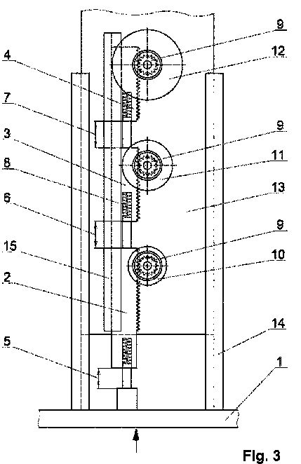


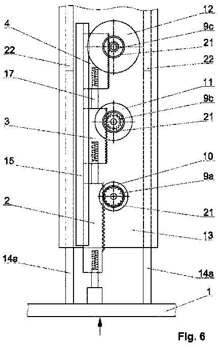


CARRYING OUT THE INVENTION
Fig. 1 shows schematically an embodiment of an underground shield with a hood 101 protected by hydraulic actuators, wherein protective arrangements, shown in details in Fig. 2, are used. The hood 101 is supported on the base 102 of the vehicle by means of hydraulic actuators 103, at the ends of which there is mounted a rotary device 1 10 for taking over and dissipating energy of impact of rocks to the hood 101 , described in details with reference to Figs. 3-8. The ram element 1 of the device 1 10 is mounted to the actuator 103 and the base plate 13 is mounted to the hood 101 .
As shown in the embodiment of Fig. 3, the rotor device for taking over and dissipating impact energy has a ram element 1 made as a beam and coupled with three racks 2, 3, 4 connected in series. Between the racks 2, 3, 4, as well as between the ram element 1 and the first rack 2 distances 5, 6, 7 are formed which enable an action of cushioning elements 8 and cause that the racks 2, 3, 4 shift in relation to one another, as well as in relation to the ram element 1 . Each of the racks 2, 3, 4 meshes with a toothed wheel 9 driving a kinetic energy rotary accumulator 10, 1 1 , 12, whereas in order to achieve greater effectiveness of impact energy receiving and dissipating, the first kinetic energy rotary accumulator 10 driven by the first rack 2 has the least inertia moment, the second kinetic energy rotary accumulator 1 1 driven by the second rack 3 has an average inertia moment, and the third kinetic energy rotary accumulator 12 driven by the third rack 4 has the greatest inertia moment.
The ram element 1 is slidably engaged with side walls of a body plate 13 by means of ram runners 14, whereas these ram runners 14 are fastened perpendicularly to the ram element 1 . Moreover, a runner 15 is fastened to the body plate 13, said guide ensuring shifting of the racks 2, 3, 4 in a suitable distance from the toothed wheels 9.
As it is shown in Fig. 4, the cushioning elements 8 are located in cylindrical openings 16 made in the racks 2, 3, 4. These openings cooperate with pressing mandrels 17 carrying impact energy from the ram element 1 onto the consecutive racks 2, 3, 4. In embodiments illustrated in the figure the cushioning elements 8 have a form of helical springs, however this solution does not limit the possibility of using other cushioning elements such as, in particular, fluid or elastomer absorbers.
As it is schematically shown in the cross section in Fig. 5, in an opening 18 formed in the body plate 13 there is an axle 19 tightly fastened, with the rotatably mounted toothed wheel 9 combined with an internal bush 20 of the kinetic energy rotary accumulator 12. The kinetic energy rotary accumulator 12 has furthermore a one-way clutch 21 of the known construction situated in the annular space around the internal bush 20.
In the second embodiment of the device according to the invention presented in Fig. 6, there are used the kinetic energy rotary accumulators 10, 1 1 , 12 having different moments of inertia and rack transmissions having different transmission ratios as the result of different pitch diameters of the used toothed wheels 9a, 9b, 9c. The kinetic energy rotary accumulator 10 having the least moment of inertia is driven by means of the toothed wheel 9a having the greatest pitch diameter, and the kinetic energy rotary accumulator 12 having the greatest moment of inertia is driven by means of the toothed wheel 9c having the least pitch diameter. This construction according to the invention makes it possible to obtain increased progressiveness of taking over the impact energy by successively started kinetic energy rotary accumulators. The characteristic of the progressiveness of taking over the impact energy by the consecutive kinetic energy rotary accumulators 10, 1 1 , 12 in the embodiment shown in Fig. 6 can be therefore shaped across by selecting pitch diameters of the driving toothed wheels 9a, 9b, 9c and by selecting moments of inertia of the consecutive kinetic energy rotary accumulators 10, 1 1 , 12.
The arrow which is perpendicular to the external surface of the ram element drawn in Fig. 3, Fig. 4 and Fig. 6 shows the expected direction of an impact load. Every angular deflection of the impact load from the expected direction increases the probability of the damage of the device and causes the reduction of the efficiency of taking over and dispersing impact energy. Therefore, the device according to the invention should be mounted in objects exposed to results of the unexpected collision in such a way that the expected impact load is substantially perpendicular to the external surface of the ram element 1 .
In the embodiment shown in Fig. 6 the ram element 1 is connected slidably with the body plate 13 by means of ram runners 14a which are mounted slidably in openings 22 made in the body plate 13 parallel to the runner 15 of the racks 2, 3, 4. Such a solution provides the increased shape rigidity of the whole device and can be used also in case of larger angular deviations of the impact load from the direction perpendicular to the external surface of the ram element 1 .
As it is shown in Fig. 7, one-way clutch 21 of the known construction is situated between the inner bush 20 and an inner surface of the kinetic energy rotary accumulator 1 1 .
The one-way clutch 21 is used to transmit the torque from the internal bush 20 to the kinetic energy rotary accumulator 10, 1 1 , 12. After taking over the impact energy, when the angular speed of the internal bush 20 is smaller than the angular speed of the suitable kinetic energy rotary accumulator 10, 1 1 , 12, the one-way clutch 21 is disconnected to enable free rotation of the kinetic energy rotary accumulator 10, 1 1 , 12.
Thanks to enabling the free rotation of the kinetic energy rotary accumulators 10, 1 1 , 12 the kinetic energy stored in a short time of an impact can be dissipated in a significantly longer time.
In Fig. 8 the device according to the invention is shown during taking over the impact energy. Sliding linear motions and rotary motions of particular parts of the device respectively are shown in this figure with arrow lines. To enable taking over of the impact energy by the device according to the invention, the body plate 13 is fastened to the hood 101 (not shown in the drawing) by fastening elements 23. Depending on energy taking over capacity of the device according to the invention, fastening elements 23 can be realized by welding, riveting, gluing, screwing and any other possible connections which can be used in a construction of an object protected against results of a collision.
The energy acting during the impact on the ram element 1 , transferred by racks 2, 3, 4 to the kinetic energy rotary accumulators 10, 1 1 , 12, is initially absorbed by the cushioning elements 8. Because of a serial connection of racks 2, 3, 4, the kinetic energy rotary accumulators 10, 1 1 , 12 begin their work one after another starting from the kinetic energy rotary accumulator 10 having the least moment of inertia, and finishing with the kinetic energy rotary accumulator 12 having the greatest moment of inertia. In the solution according to the invention the maximum idle stroke of the ram element 1 in relation to the last rack 4 which drives the kinetic energy rotary accumulator 12 having the greatest moment of inertia is equal to the sum of distances 5, 6, 7 between the ram element 1 and the first rack 2, as well as among particular racks 2, 3, 4.
In the device according to the invention, in the working position illustrated in Fig. 8 during taking over of the impact energy, the distances 5, 6, 7 existing in the rest state are decreased to the size 5a, 6a, 7a. At such position of the racks 2, 3, 4 all of the kinetic energy rotary accumulators 10, 1 1 , 12 are driven, whereas in this position the kinetic energy accumulator 10 having the least moment of inertia has the greatest angular speed, the kinetic energy accumulator 1 1 having the average moment of inertia has the average angular speed, and the kinetic energy accumulator 12 having the greatest moment of inertia has the least angular speed.
In case of taking over greater impact energies by the rotor device according to the invention, the distances 5a, 6a, 7a can reach the zero value and in this case linear speeds of the moving racks 2, 3, 4 are equal, and at equal ratios of the rack transmissions, the angle velocities of the kinetic energy rotary accumulators 10, 1 1 , 12 are also equal.
Method & Device for Vehicle Protection
The method of vehicle protection against a crash and/or sudden braking and/or vibrations caused by road unevenness and/or other bodies with high kinetic energy such as stones or bullets impacting on the vehicle consists in that suddenly produced kinetic energy is immediately converted and stored in an energetic accumulating converter (6), in particular, the kinetic energy produced by a force acting on the vehicle's bumper is converted into rotational energy, which set impeller(s) in motion. The device as above includes a system, which converts straight-line motion energy into rotational energy.
The method of vehicle protection against a crash and/or sudden braking and/or vibrations caused by road unevenness and/or other bodies with high kinetic energy such as stones or bullets impacting on the vehicle
This invention set forth the method of vehicle protection against a crash and/or sudden braking and/of vibrations caused by road unevenness and/or other bodies with high kinetic energy such as stones or bullets impacting on the vehicle and the related device.
According to the solutions known, vehicles are protected by means of elements absorbing energy, which is produced during a crash in large quantities in very short time intervals measured in milliseconds. Usually, such elements include bumpers with a variety of constructions that absorb crash energy, however a very small portion of that produced. As a result, the whole vehicle is subject to deformation until it is crushed and huge force (inertia, overloads) that act on passengers and luggage make them move and even throw them away from the vehicle. So, passengers are subject to not only bodily injury caused by the car body being crushed but also by the car components such as engine, gear box and steering system that move inwards the body.
In order to counteract these ufavourable effect,s in some vehicles shock absorbers have been used in classic bumper constructions specific to solutions that damp sudden forces.
However, the results obtained have been unsatisfactory.
The proposed method allows the above described dangers to be avoided or limited to a great extent.
The method under consideration consists in that suddenly produced kinetic energy is immediately converted and stored in an accumulating converter.
In particular, the kinetic energy produced by the force acting on the vehicle's bumper is converted into rotational energy which set impellers) in motion.
The device invented has a bumper and energy absorbing system, which converts straight-line motion energy into rotational energy.
The first implementation option of the system, which converts straight-line motion energy into rotational energy, includes a guide mating with the bumper and equipped with a toothed bar. The guide is connected with a toothed wheel of a gear and the toothed bar has, on a part of its circumference, a toothed wheel mating with a disc with a rack, which is significantly lower in diameter than the part of circumference. (see Figure 1).
The second implementation option includes a converter mating with the bumper. The converter consists of a block with U-shaped cutting,s another similar block also with U- shaped cuttings with different width that are displaced against the cuttings of the first Mock, rollers located at the ends of protrusions formed by cuttings, and a string spanning the two blocks and wound on accumulating discs.
The device invented is shown as some implementation examples on the following
Figure 1 presents the first implementation option of the invention.
Figure 2 presents the second implementation option of the invention, and
Figure 3 presents another implementation option.


The device shown in Figure 1 has a guide equipped with a toothed bar. The toothed bar mates with a pinion of a gear with a large toothed wheel on a part of its circumference, whereas the latter Slates with a pinion of rotary disc, which forms a kinetic energy accumulator. Upon impact on the bumper the pinion of the gear is set in motion thereby actuating the large toothed wheel of the gear on a part of its circumference. At the same time, the pinion of the rotary accumulating disc is set in motion to take energy from the bumper. The pinion will immediately be disconnected after it has mated with the large toothed wheel of the gear on a part of its circumference.
Figure 2 presents the second implementation option of the invention. Upon action of a force on the bumper, the protrusions of one block ended with rollers move and come into the cuttings of the other Mock. At the same time, the string is deformed from a straight-line form into a wave form, so the string is pulled out from the accumulating discs thereby setting them in rotation result iii the transfer of the bumper's energy to the accumulating discs and its its conversion into energy needed to rotate the discs. So straight-line motion energy is converted into rotational energy. The harmful bumper's energy acting along a saint line is neutralised.
Figure 3 presents another implementation option.
As previously mentioned, the invention allows a motor vehicle to be protected by means of energetic bumper, energetic brake, energetic vibration dampers and energetic armour against a crash and/of sudden braking and/or vibrations caused by unevenness and/or other bodies with high kinetic energy such as stones or bullets impacting on the vehicle and energy to be accumulated. It will be the vehicle's energy in the event of crashing into an obstacle, the total energy of two vehicles in the event of two vehicles crashing into each other (if the other vehicle has no device according to the invention installed), the energy of stone/bullet in the event of its impact, the vehicle's energy in the event of braking and finally, the vehicle's mechanical vibraiton energy in the event of vibrations.
The Energy Converter and Accumulator (ECA) takes the kinetic energy from a vehicle when crashing or braking ad converts it into the kinetic energy of a rotary element (mechanical accumulator). The rotary element is a component of the ECA and accumulates a significant part or almost the whole energy of a vehicle in motion. The ECA must convert energy within such a time interval that is shorter than that causing irreversible crash effects, i. e. shall be measured in milliseconds. The ECA accumulates the vehicle's kinetic energy in an impeller whose mass is as little as about one per cent (10/o) of the vehicle ! s mass. Such a high kinetic energy is accumulated by the ECA m such a small mass by rotating the impeller at very high speed amounting to tenths of nds rpm or even more. The vehcile's energy flows to the ECA through mechanical transmissions : gear., string ones, magnetic or hybrid transmissions with fixed or variable transmission ratios. Energy is accumulated in the form of rotational energy of impellers with a fixed or variable moment of inertia during the process.
The ECA operation, and thereby the protection method, is based on the energy conservation law. The vehicle in motion, from which energy is taken, transferred and converted into the energy of a different object (in this case ECA) becomes safe.
The energy of any object being in rotary motion is determined by the following formulae: Ekrm=I0#02 where: Ekm = kinetic energy being in rotary motion of the object whose energy is to be absorbed, I0-the object's moment of inertia, @0-the objects angular velocity.
The energy of any object being in translatory motion is determined by the following formulae : E = m0V02 where : Ektm = kinetic energy int ranslatory motion of the object whose energy is to be absorbed, mo-the object's mass, Vo-the object's linear velocity.
The kinetic energy of the ECA's accumulator being in rotary motion is determined by the following formulae : Ekrma=Ia#a2 where : Ekm = =kinetic energy of the accumulator absorbing and accumulating the object's energy,
Ia - the accumulator's moment of inertia, #a - the accumulator's angular velocity.
Any vehicle will be protected effectively against any crash effects when the ECA takes as much as possible kinetic energy of the vehicle in motion (boejct) and accumulates it as rotational energy, i.e. Ekrma as determined by formulae (3) is close to the objects energy as determined by formula (2) or (1). The time limits as mentioned above must be observed in the process of energy flow from the object to the ECA.
Figure 1 presents the first implementation option of the ECA device, which converts translatory motion energy of a moving object into rotatioaai energy-The system consists of base 1 immovaly fixed to the protected vehicle, element, movable against the base, taking impact force and transferring energy 2, flexible element 3 attached to the movable element 2, gear 4 converting translatory motion into rotary motion, multiplying gear 5, which transfers kinetic energy to energy accumulator 6 Once a force has acted on element (2) and energy flowed to accumulator 6, both gears 5 and 6 will disconnect thus enabling the accumulator to store for a longer time the energy taken. The ECA system shown in Figure 1 is designed as a twin version, i.e. there are two symmetrically located gears and accumulators.
Figure 2 presents the other implementation option of the ECA system, which consists of base 1 immovably fixed to the protected vehicle, fixed part 22 of the string transmission
connected immovably with the base, movable part 23 of the string transmission, rollers 24 guiding the string in both the fixed and movable part, string 25, parts on which the string is wound 26 (the cross section of elements can be a circle, scroll, cam to enable torque's arm to be changed), energy accumulators 27, element to take impact force and transfer energy 28, connected immovably with the movable part of the roller trnasmission. Upon crash, the movable part of the roller transmission slides along the guides into the fixed part and tightens the string guided by the rollers. The tightened string is unwound from part 26 and sets the accumulators in rotation as parts 26 are immovably connected with the accumulators. By setting the energy accumulators in rotation they take and accumulate energy of the protected vehicle. This ECA design option of the system consists of one string transmission, which transfers energy to two energy accumulators.
Figure 3 shows another implementation option of the invention. Here, the ECA device consists of base @ 1 immovably fixed to the protected vehicle, part taking force and transferring crash energy 32, toothed bar 33, toothed gear 34 to convert translatory motion into rotation, mechanical accumulators 35 to take and store the vehicle's kinetic energy to be converted into rotational energy. Set into rotation, the energy accumulators are immovably connected with the toothed wheels of gear 34 The accumulators have movable parts 36, which after actuating an accumulator move outwards of the rotation axis due to centrifugal force thus increasing the accumulator's moment of inertia. It is easier to start up the accumulator with variable moment of inertia as it starts to move at a lower moment of inertia. The ECA system shown in Figure 3 is a twin version including two gears and two accumulators. In case of a crash, energy is trnasferred to the gears and then converted into kinetic rotational energy. which is stored in the accumulator. Once part 32 has been moved due to a crash and the related energy transferred to the accumulator by gear 34 the gear is disconnected.
Thanks to the invention, in addition to the vehicle's protection, inertia forces acting on masses in the vehicle (people, luggage) are reduced. Such reduction may exceed 90% as compared with those ose values when the invention is not used.
The invention can replace the action of bumpers, crumple zones, shields and armours with separate devices, with different performance and accumulated energy, to be used for each of the above mentioned tasks-
Use of energy conversion and accumualtion to repalce crumple zones, friction brakes, shock absorbers, stiff shields and armours.
It should be stressed that the invention can be used to eliminate inertia forces, i.e. when braking aeroplanes at short runways such as on aircraft carriers, touching an aeroplane with the ground (absorbing inertia forces), as well as, to brake ships or generally speaking - to liquidate inertia forces acting on any object by converting the object's kinetic energy into the kinetic energy of devices purposely built according to this invention.
The use of the ECA system as an energetic brake is similar to that as a bumper but much simpler, since there is no need to convert translatory motion into rotation.
AN ARRANGEMENT FOR PROTECTION OF HYDRAULIC ACTUATORS OF UNDERGROUND SHIELD
FROM DYNAMIC OVERLOAD...
TECHNICAL FIELD
The object of the present invention is an arrangement for protection of hydraulic actuators of underground shield from dynamic overload with a mechanical rotary absorber.
BACKGROUND ART
Underground vehicles are prone to falling rocks from the top parts of the heading. In order to effectively protect the personnel or equipment moving by the underground vehicle, the vehicle should have a robust hood. The hoods are usually mounted on stiff arms or arms with hydraulic actuators.
There are known powered underground shields protecting from fall of rock having a hood supported by means of a telescopic support on a base. Typical powered underground shields are disclosed in WO201 1/039693 or US7377727. These vehicles have telescopic supports configured to dampen the fall by hydraulic actuators, such as gas or oil dampers mounted within the supports. In order to effectively dampen the fall, the actuators must keep high efficiency. Keeping the efficiency and leakproofness of the actuators in the hard working conditions of the underground shields may cause problems.
It would be advantageous to provide an alternative mechanism for protecting the actuators of the underground shield from dynamic load.
WO2004028864 discloses a rotor device for taking over and dissipating impact energy, in which kinetic energy suddenly created by a collision is converted into kinetic energy of rotating masses. In this known solution a ram element is connected with two racks which drive by means of gears the rotors shaped as rods with movable weights sliding on them. Minimizing of percussive load of cooperating elements in the preliminary phase of the energy transfer is realized in the known solution by using movable weights situated possibly near a rotation axis of a bar-rotor so as to achieve a minimum moment of inertia of the rotor in this initial phase. In the further stage of this motion, when the rotor begins its rotation, these weights are moved by the centrifugal force increasing their distance from the rotation axis along the bar axis till reaching the extreme position near the end limiters. In this position the highest moment of inertia of the rotor is achieved, enabling the takeover of increased kinetic energy.
A rotor device for taking over and dissipating kinetic impact energy is also known from patent application WO2005121593, said device comprising a ram element cooperating with a rack making, by means of a toothed wheel, a kinetic energy rotary accumulator to rotate in order to convert impact energy into kinetic energy of rotary motion of the rotary accumulator. In one of embodiments of the known rotor device for taking over an impact energy a kinetic energy rotary accumulator cooperates with movable weights maintained in a suitable distance from a rotation axis by means of springs. Such a solution provides gradual increment of the ability of the device to take over kinetic energy during an impact.
WO2004053352 discloses a device for absorbing kinetic energy, comprising a rotor coupled with a bumper via a multiplying gear.
DE3141024 discloses a device for converting energy generated by an oscillating mass to an energy for driving a rotatable element by means of a rotatable shaft coupled with a hydraulic system.
The solutions described above do not provide efficient conversion of energy for various impact speeds and various masses of the impacting objects.
PCT/PL201 1/050060 (known to the inventors and not published before the priority date of the present application) discloses a rotary device for absorbing and dissipating energy of impact, used to convert kinetic energy of translational movement to kinetic energy of rotational movement. A ram element cooperates with at least two serially connected racks slidably mounted on a runner and driving the toothed wheels of the kinetic energy rotary accumulators. Distances are created between the ram element and the first rack and moreover distances are created between the racks to ensure the action of cushioning elements and to enable shifting of the ram element in relation to the racks, as well as shifting of these racks in relation to one another.
The invention presented in PCT/PL201 1/050060 is new and inventive over the solutions described before, as it allows gradual damping with increasing efficiency of energy dissipation in relation to the speed and mass of the objects under impact. By providing cushioning elements between the rotary absorbers, the load can be transferred gradually to successive absorbers and the moment of inertia can be gradually increased, thereby gradually adapting to the energy of impact. Such solution was neither known nor suggested by any of the previous publications.
The object of the invention is a new use of the rotary device for absorbing and dissipating energy of impact known from PCT/PL201 1/050060, in particular the use for absorbing impacts imparted to hydraulic actuators of an underground shield.
DISCLOSURE OF THE INVENTION
The object of the invention is a protective arrangement for hydraulic actuators of an underground shield from dynamic overload with a mechanical rotary absorber, characterized in that it comprises a hydraulic actuator mountable to the base of the underground shield, to which there is connected a rotary device for taking over and dissipating the energy of rocks falling on the hood, wherein the device for taking over and dissipating energy comprises a ram element mounted to the actuator, slidably coupled by means of ram guides with side walls of a base plate mountable to the hood, which cooperates with at least two serially connected racks mounted slidably on a runner and driving toothed wheels of the kinetic energy rotary accumulators, wherein distances are created between the ram element and the first rack, as well as between the particular racks, said distances enabling the displacement of the ram element in relation to racks, as well as the displacement of these racks in relation to one another, such as to enable the moving ram element to pass the kinetic energy of the translational movement to the kinetic energy rotary accumulators in order to transform it to the kinetic energy of rotational movement.
Preferably, the kinetic energy rotary accumulators have different energy accumulating abilities.
Preferably, the kinetic energy rotary accumulators have different moments of inertia.
Preferably, the kinetic energy rotary accumulator driven by the first rack has a smaller moment of inertia than the kinetic energy rotary accumulator driven by the second rack.
Preferably, the kinetic energy rotary accumulators are driven by transmissions increasing angular speed, which have different transmission ratios.
Preferably, the kinetic energy rotary accumulator has a one-way clutch. The protective arrangement according to the invention comprises a device for absorbing and dissipating energy of impact, wherein as a result of serial connection of the ram element with at least two serially connected racks which drive toothed wheels of kinetic energy rotary accumulators, with distances provided between the said racks, it is assured gradual driving in rotation of the subsequent kinetic energy rotary accumulators, what enables an abrupt increase of energy taking over ability of the device according to the invention. Cushioning elements fastened in the front of the racks in series decrease the percussive load of elements cooperating when starting the subsequent kinetic energy accumulators. The device according to the invention is suitable both for taking over small as well as great impact energy. In the first case the device ensures the effective and very gentle takeover of the impact energy because kinetic energy of progressive motion is carried out by kinetic energy rotary accumulators having the least moment of inertia. In the second case the device according to the invention provides also effective and uniform dissipation of the impact energy because taking over of kinetic energy of progressive motion is carried out by several kinetic energy rotary accumulators having ever greater energy taking over ability.
In a case of collisions of greater energy, in the device according to the invention there appears also an additional beneficial effect consisting in that kinetic impact energy, before being taken over by the kinetic energy rotary accumulators having the greater moment of inertia, is accumulated in its substantial part by kinetic energy rotary accumulators having the smaller moment of inertia. Such an order of taking over the energy provides the gentler operation of the device according to the invention during starting of next kinetic energy rotary accumulators, even those having the greatest moment of inertia.
By using a one-way clutch, the free rotation of the kinetic energy rotary accumulator is provided after taking over the impact energy until the energy accumulated in it is dissipated.
Therefore, it is possible to absorb impacts on the hood from rocks of different masses, falling from different heights. This allows to make the hood 101 from lighter materials than in case of hoods that are not so effectively dampened.
BRIEF DESCRIPTION OF DRAWINGS
The object of the invention is shown by means of exemplary embodiments on a drawing, in which:
Fig. 1 shows an exemplary embodiment of an underground shield,
Fig. 2 shows schematically the protective arrangement according to the invention,
Fig. 3 shows the first embodiment of the rotor device for taking over and dissipating impact energy in a top view,
Fig. 4 presents the device from Fig. 3 in the side view,
Fig. 5 presents a cross section through the axis of the kinetic energy rotary accumulator along the line A-A marked in Fig. 4,
Fig. 6 presents the second embodiment of the device in a top view, having kinetic energy rotary accumulators of the differentiated moment of inertia, in which the rack transmissions with different gear ratios are used,
Fig. 7 presents an enlarged cross section of the rotary kinetic energy accumulator, and
Fig. 8 presents the device in its first embodiment during receiving impact energy where a rotation direction as well as shifting direction of particular parts of the device in action are marked.
MODES FOR CARRYING OUT THE INVENTION
Fig. 1 shows schematically an embodiment of an underground shield with a hood 101 protected by hydraulic actuators, wherein protective arrangements, shown in details in Fig. 2, are used. The hood 101 is supported on the base 102 of the vehicle by means of hydraulic actuators 103, at the ends of which there is mounted a rotary device 1 10 for taking over and dissipating energy of impact of rocks to the hood 101 , described in details with reference to Figs. 3-8. The ram element 1 of the device 1 10 is mounted to the actuator 103 and the base plate 13 is mounted to the hood 101 .
As shown in the embodiment of Fig. 3, the rotor device for taking over and dissipating impact energy has a ram element 1 made as a beam and coupled with three racks 2, 3, 4 connected in series. Between the racks 2, 3, 4, as well as between the ram element 1 and the first rack 2 distances 5, 6, 7 are formed which enable an action of cushioning elements 8 and cause that the racks 2, 3, 4 shift in relation to one another, as well as in relation to the ram element 1 . Each of the racks 2, 3, 4 meshes with a toothed wheel 9 driving a kinetic energy rotary accumulator 10, 1 1 , 12, whereas in order to achieve greater effectiveness of impact energy receiving and dissipating, the first kinetic energy rotary accumulator 10 driven by the first rack 2 has the least inertia moment, the second kinetic energy rotary accumulator 1 1 driven by the second rack 3 has an average inertia moment, and the third kinetic energy rotary accumulator 12 driven by the third rack 4 has the greatest inertia moment.
The ram element 1 is slidably engaged with side walls of a body plate 13 by means of ram runners 14, whereas these ram runners 14 are fastened perpendicularly to the ram element 1 . Moreover, a runner 15 is fastened to the body plate 13, said guide ensuring shifting of the racks 2, 3, 4 in a suitable distance from the toothed wheels 9.
As it is shown in Fig. 4, the cushioning elements 8 are located in cylindrical openings 16 made in the racks 2, 3, 4. These openings cooperate with pressing mandrels 17 carrying impact energy from the ram element 1 onto the consecutive racks 2, 3, 4. In embodiments illustrated in the figure the cushioning elements 8 have a form of helical springs, however this solution does not limit the possibility of using other cushioning elements such as, in particular, fluid or elastomer absorbers.
As it is schematically shown in the cross section in Fig. 5, in an opening 18 formed in the body plate 13 there is an axle 19 tightly fastened, with the rotatably mounted toothed wheel 9 combined with an internal bush 20 of the kinetic energy rotary accumulator 12. The kinetic energy rotary accumulator 12 has furthermore a one-way clutch 21 of the known construction situated in the annular space around the internal bush 20.
In the second embodiment of the device according to the invention presented in Fig. 6, there are used the kinetic energy rotary accumulators 10, 1 1 , 12 having different moments of inertia and rack transmissions having different transmission ratios as the result of different pitch diameters of the used toothed wheels 9a, 9b, 9c. The kinetic energy rotary accumulator 10 having the least moment of inertia is driven by means of the toothed wheel 9a having the greatest pitch diameter, and the kinetic energy rotary accumulator 12 having the greatest moment of inertia is driven by means of the toothed wheel 9c having the least pitch diameter. This construction according to the invention makes it possible to obtain increased progressiveness of taking over the impact energy by successively started kinetic energy rotary accumulators. The characteristic of the progressiveness of taking over the impact energy by the consecutive kinetic energy rotary accumulators 10, 1 1 , 12 in the embodiment shown in Fig. 6 can be therefore shaped across by selecting pitch diameters of the driving toothed wheels 9a, 9b, 9c and by selecting moments of inertia of the consecutive kinetic energy rotary accumulators 10, 1 1 , 12.
The arrow which is perpendicular to the external surface of the ram element drawn in Fig. 3, Fig. 4 and Fig. 6 shows the expected direction of an impact load. Every angular deflection of the impact load from the expected direction increases the probability of the damage of the device and causes the reduction of the efficiency of taking over and dispersing impact energy. Therefore, the device according to the invention should be mounted in objects exposed to results of the unexpected collision in such a way that the expected impact load is substantially perpendicular to the external surface of the ram element 1 .
In the embodiment shown in Fig. 6 the ram element 1 is connected slidably with the body plate 13 by means of ram runners 14a which are mounted slidably in openings 22 made in the body plate 13 parallel to the runner 15 of the racks 2, 3, 4. Such a solution provides the increased shape rigidity of the whole device and can be used also in case of larger angular deviations of the impact load from the direction perpendicular to the external surface of the ram element 1 .
As it is shown in Fig. 7, one-way clutch 21 of the known construction is situated between the inner bush 20 and an inner surface of the kinetic energy rotary accumulator 1 1 .
The one-way clutch 21 is used to transmit the torque from the internal bush 20 to the kinetic energy rotary accumulator 10, 1 1 , 12. After taking over the impact energy, when the angular speed of the internal bush 20 is smaller than the angular speed of the suitable kinetic energy rotary accumulator 10, 1 1 , 12, the one-way clutch 21 is disconnected to enable free rotation of the kinetic energy rotary accumulator 10, 1 1 , 12.
Thanks to enabling the free rotation of the kinetic energy rotary accumulators 10, 1 1 , 12 the kinetic energy stored in a short time of an impact can be dissipated in a significantly longer time.
In Fig. 8 the device according to the invention is shown during taking over the impact energy. Sliding linear motions and rotary motions of particular parts of the device respectively are shown in this figure with arrow lines. To enable taking over of the impact energy by the device according to the invention, the body plate 13 is fastened to the hood 101 (not shown in the drawing) by fastening elements 23. Depending on energy taking over capacity of the device according to the invention, fastening elements 23 can be realized by welding, riveting, gluing, screwing and any other possible connections which can be used in a construction of an object protected against results of a collision.
The energy acting during the impact on the ram element 1 , transferred by racks 2, 3, 4 to the kinetic energy rotary accumulators 10, 1 1 , 12, is initially absorbed by the cushioning elements 8. Because of a serial connection of racks 2, 3, 4, the kinetic energy rotary accumulators 10, 1 1 , 12 begin their work one after another starting from the kinetic energy rotary accumulator 10 having the least moment of inertia, and finishing with the kinetic energy rotary accumulator 12 having the greatest moment of inertia. In the solution according to the invention the maximum idle stroke of the ram element 1 in relation to the last rack 4 which drives the kinetic energy rotary accumulator 12 having the greatest moment of inertia is equal to the sum of distances 5, 6, 7 between the ram element 1 and the first rack 2, as well as among particular racks 2, 3, 4.
In the device according to the invention, in the working position illustrated in Fig. 8 during taking over of the impact energy, the distances 5, 6, 7 existing in the rest state are decreased to the size 5a, 6a, 7a. At such position of the racks 2, 3, 4 all of the kinetic energy rotary accumulators 10, 1 1 , 12 are driven, whereas in this position the kinetic energy accumulator 10 having the least moment of inertia has the greatest angular speed, the kinetic energy accumulator 1 1 having the average moment of inertia has the average angular speed, and the kinetic energy accumulator 12 having the greatest moment of inertia has the least angular speed.
In case of taking over greater impact energies by the rotor device according to the invention, the distances 5a, 6a, 7a can reach the zero value and in this case linear speeds of the moving racks 2, 3, 4 are equal, and at equal ratios of the rack transmissions, the angle velocities of the kinetic energy rotary accumulators 10, 1 1 , 12 are also equal.
SUPPORT UNIT OF INTERNAL COMBUSTION ENGINE
The present invention relates to support unit of internal combustion engines, in which there are at least two energy-consuming support brackets between the combustion engine block and the body supporting structure, wherein at least one of supporting brackets is a rotor arrangement for absorbing and dissipating kinetic energy, in which kinetic energy of a progressive movement is converted into rotational movement kinetic energy, and the rotor arrangement comprises slidable support fixed to the engine block and a housing fixed to the body supporting structure, between which two racks are installed being in mesh with toothed wheels driving the kinetic energy rotor accumulators of determined moment of inertia, characterized in that, the slidable support (9) cooperates with at least two serially coupled racks (12, 13, 14), slidably installed in the housing (19); and driving toothed wheels (15) of the kinetic energy rotor accumulators (16, 17, 18), wherein between the slidable support (9) and the first rack (12), as well as between the racks (12, 13, 14), gaps are defined, and between at least two serially coupled racks (12, 13, 14) a shock absorbing elements (20) are situated, enabling for translocation of the racks (12, 13, 14) with relation to each other.
Unbalanced forces and moments of force existing during operation of internal combustion engines, in particular the one of a number of cylinders smaller than six, induce vibrations of the whole vehicle body, thus resulting in a decrease of a travelling comfort. Furthermore the support points of internal combustion engines, in particular in motorcars, require specific constructional reinforcements in regards to great individual tensions related with a necessity of shock absorption of the considerable engine mass.
Known support arrangements of internal combustion engines usually comprise a metal-rubber support bracket embedded on a specifically reinforced support construction of the body. In a case of occurrence great random vibrations caused by irregular work of an engine and by force caused by the vehicle wheels, such metal- rubber support brackets do not provide high efficiency of energy accumulation.
Known support arrangements of internal combustion engines can use also hydraulic systems, such as shock absorber as disclosed in PL164107, in which between supporting elements of vibrating device two-sided piston rod is situated. Vibration of the supported device drive piston rod, which pumps oil over from one chamber to another. Throttle of flowing oil causes conversion of kinetic energy of vibration into heat.
German patent application DE3141024 discloses a device for generation of energy by using vibrations of other devices. In this known solution vibrations are converted into kinetic energy of a rotational movement. Torque generated in this manner is transferred by medium of toothed gear, with employment of fly-wheels, and also by hydraulic arrangements in order to be used for driving other electrical or mechanical devices.
From international patent application WO2004028864 a device for absorbing and dissipating impact energy is known, in which kinetic energy generated rapidly in a result of an impact is converted into kinetic energy of rotating masses. In this known solution a beater element is connected with two toothed bars which by medium of toothed wheels drive rotor in forms of rods with moveable weights slidably mounted on the rods. Minimalization of impact load of the cooperating elements during the initial phase of an energy transfer is realized in this known solution by employment of the moveable weights disposed as close as possible to the rotation axis of the rotor in order that a moment of inertia of the rotor in this phase be as small as possible. In a further movement phase while the rotor starts to rotate, the weights start to translocate under influence of centrifugal force and move away from the rotation axis along the rod axis, until they reach their terminal positions in the vicinity of the end limiters. In such positions of the weights the biggest moment of inertia of rotor is achieved that enables for absorption of the increased kinetic energy.
International application WO2005121593 discloses a device for absorbing energy comprising a beater element cooperating with an energy dissipation arrangement comprising a toothed bar inducing rotation of rotating masses, thus causing a conversion of progressive movement kinetic energy resulted from an impact into kinetic energy of a rotational movement. In one of disclosed embodiments of this known solution, the toothed bar drives a rotor by means of a toothed wheel, wherein the rotor cooperates with a moveable weights. In order to provide a progressive change of a moment of inertia of the rotor during a process of energy absorption, the moveable weights are maintained in appropriate distance from a rotation axis by means of springs.
The known solutions do not provide effective absorption of different amounts of vibration energy related with different amplitudes of vibrations. Therefore the object of the present invention is to provide better efficiency of absorption of different random vibrations occurring between the body and the engine and dissipation of energy of these vibrations to not to transfer vibrations to the whole body.
According to the present invention, there are at least two energy-consuming support brackets between the combustion engine block and the body supporting structure, wherein at least one of supporting brackets is a rotor arrangement for absorbing and dissipating kinetic energy, in which kinetic energy of a progressive movement is converted into rotational movement kinetic energy, and the rotor arrangement comprises slidable support fixed to the engine block and a housing fixed to the body supporting structure, between which racks are installed being in mesh with toothed wheels driving the kinetic energy rotor accumulators of determined moment of inertia. The present invention is characterised in that the slidable support cooperates with at least two serially coupled racks slidably installed in the housing and driving toothed wheels of the kinetic energy rotor accumulators. Between the slidable support and the first rack, as well as between the racks, gaps are defined, and between at least two serially coupled racks a shock absorbing elements are situated enabling for translocation of the racks with relation to each other.
The kinetic energy rotor accumulators preferably have differentiated capability of energy accumulation.
The kinetic energy rotor accumulators preferably have differentiated moments of inertia.
By means of the gaps defined between the racks and by means of shock absorbing elements situated between at least two serially coupled racks there is provided a gradual actuation of successive kinetic energy rotor accumulators. That enables for adjustment of capability of shock absorption of support unit with relation to varied amplitude of vibrations of engines and forces existing during rocking of body when driving over rough road surfaces.
Use of differentiated moments of inertia of successive kinetic energy rotor accumulators, especially if kinetic energy rotor accumulator driven by means of the first rack has smaller moment of inertia that the moment of inertia of the kinetic energy rotor accumulator driven by means of the second rack, enables for smooth and gradual increase of capability of kinetic energy accumulation in case of vibrations of big amplitude.
The support unit according to the present invention is suitable for absorbing energy in case of vibrations of small amplitude and low kinetic energy as well as in case of vibrations of big amplitude and high kinetic energy. In the first instance, the support unit according to the present invention provides an efficient and very smooth shock absorption of vibrations, as an absorption of kinetic energy of progressive movement takes place with using kinetic energy rotor accumulators of the smallest moment of inertia. In the second instance, the support unit according to the present invention also provides appropriately efficient and smooth shock absorption of vibrations, as kinetic energy absorption takes place with using several rotor accumulators of increasing energy.
In case of vibrations of greater energy, an additional effect occurs consisting in that vibrations kinetic energy is in a great part accumulated in the rotor accumulators featuring lower energy absorption capability before the rotor accumulators featuring higher energy absorption capability are actuated. Such a sequence of energy absorption provides smoother operation of the support unit according to the present invention during actuation of next rotor accumulators, even those of the greatest capability of energy absorption featuring the biggest moment of inertia.
The exemplary embodiments of the present invention are schematically presented below in connection with the attached drawings on which fig. 1 shows a side view of the support unit of internal combustion engines with a cross sectional view through the body supporting structure, and fig. 2 presents a side view of the supporting bracket being a rotor arrangement for absorbing and dissipating kinetic energy.
As shown schematically in in the embodiment of Fig. 1 , the internal combustion engine 1 comprises crankshaft 2 with pistons 3. Pistons 3, as a result of reciprocatory motions, generate inertial forces 4, which by means of crankshaft bearings 5 and the crankshaft 2 are transferred to main bearing 6 of casing 7, which feet 8 are located on slidable supports 9 of energy-consuming support brackets in forms of kinetic energy absorption rotor arrangements 10 situated in profiles of the body supporting structure 11.


As shown in the embodiment of Fig. 2 the slidable support 9 of kinetic energy absorption rotor arrangement 10 is coupled with three serially connected racks 12, 13, 14. Between the racks 12,13, 14, as well as between the slidable support 9 and the first rack 12, gaps are defined enabling for proper operation of shock absorbing elements 20 in a form of helical springs and providing relative movement of racks 12, 13, 14 with relation to each other and between the slidable support 9. The return spring 21 cooperates with the last rack 14, supporting return of racks 12,13,14 to initial position. Each of the racks 12, 13, 14 is interengaged with the toothed wheel 15 driving kinetic energy rotor accumulator 16, 17, 18, wherein for providing increased efficiency of absorption and dissipation of impact energy the first kinetic energy rotor accumulator 16 driven by means of the first rack 12 has the smallest moment of inertia, the second kinetic energy rotor accumulator 17 driven by means of the second rack 13 has the medium moment of inertia, while the third kinetic energy rotor accumulator 18 driven by means of the third rack 14 has the greatest moment of inertia.
The slidable support 9 is slidably coupled with the side walls of the housing 19, to which also a guide of racks 2, 13, 14 is fixed.
A progressivity characteristic of absorption of impact energy may therefore be adjusted by appropriate selection of effective diameters of the driving toothed wheels 15 and by appropriate selection of moments of inertia of successive kinetic energy rotor accumulators 16, 17, 18.
In the disclosed exemplary embodiments of the present invention also unidirectional couplings are used (not presented on drawings), disposed between toothed wheels 15 and the kinetic energy rotor accumulator 16, 17, 18. The function of the unidirectional couplings is to transfer a torque to the kinetic energy rotor. After absorbing the energy of an impact, when the angular velocity of the appropriate toothed wheel shall be smaller than the angular velocity of the appropriate kinetic energy rotor accumulator 16, 17, 18, then the unidirectional coupling becomes disconnected thus enabling for unrestricted rotation of the kinetic energy rotor accumulator 16, 17, 18.
Energy acting during an operation of internal combustion engine 1 on the slidable support 9 is transferred by means of the racks 12, 13, 14 and the toothed wheels 15 to the kinetic energy rotor accumulators 6, 17, 18. In a result of serial arrangement of the racks 12, 13, 14, is realized a successive actuation of kinetic energy rotor accumulators 16, 17, 18 starting from the kinetic energy rotor accumulator 16 of the smallest moment of inertia, and ending with the kinetic energy rotor accumulator 18 of the greatest moment of inertia. In the solution according to the present invention, the maximal idle stroke of the slidable support 9 relative to the last rack 14 driving the kinetic energy rotor accumulator 18 of the greatest moment of inertia is the sum of the gaps between the slidable element 9 and the first rack 12 and between the racks 12, 13,14.
Road Barrier And A Method For Manufacturing Thereof
A road barrier comprising a support (101) to which a transverse beam (102) is connected via a spacer (110) such that upon impact the transverse beam (102) moves towards the support (101). The spacer (110) is movable upon impact and coupled, via coupling means (130, 150, 160, 170), with a rotatable energy absorber (140) mounted below the transverse beam (102) and comprising at least one rotor (142, 143) for absorbing in rotational movement at least part of the kinetic energy imparted to the transverse beam (102).
TECHNICAL FIELD
[0001] The present invention relates to road barriers and methods for manufacturing thereof.
BACKGROUND ART
[0002] Road barriers installed along the edges of roads protect vehicles from accidentally exiting the road. The barriers are usually made of transverse beams installed on posts.
[0003] There are known road barriers in which the beam is distanced from the post and mounted to the post via an energy absorbing spacer. A barrier of this type is known from a PCT application WOO51 18958A1, which discloses a road safety barrier wherein the beam is mounted to the post via a spring. Upon impact, the beam moves towards the post and the energy of impact is at least partially absorbed by the spring. The amount of absorbed energy is therefore dependent on the parameters of the spring.
[0004] A US patent application US20070007780 describes a kinetic energy absorber for connecting to a bumper of a car and comprising a rotor connected with the bumper via a toothed bar and a multiplying gear. Upon impact directed to the bumper, the translational motion of the bumper induces translational motion of the toothed bar, which induces rotation of the rotor. The displacement vector of the bumper is parallel to the displacement vector of the toothed bar driving the rotor.
DISCLOSURE OF THE INVENTION
[0005] The aim of the invention is to provide a road barrier with alternative energy absorbing means.
[0006] The object of the invention is a road barrier comprising a support to which a transverse beam is connected via a spacer such that upon impact the transverse beam moves towards the support. The spacer is movable upon impact and coupled, via coupling means, with a rotatable energy absorber mounted below the transverse beam and comprising at least one rotor for absorbing in rotational movement at least part of the kinetic energy imparted to the transverse beam.
[0007] The rotatable energy absorber can be fixed to the support.
[0008] The coupling means may comprise a rack having a first toothed bar coupled via a toothed wheel with a toothed bar of the spacer and a second toothed bar coupled via a toothed wheel transmission with the at least one rotor.
[0009] The spacer can be configured to move in a substantially horizontal direction and the rack is configured to move in a substantially vertical direction.
[0010] The rack may comprise a compressible element.
[0011] The coupling means may comprise a strand connected at a first end to the spacer and at a second end to the rotatable energy absorber.
[0012] The strand can be wound at the second end around a driving shaft of the rotatable energy absorber.
[0013] The strand can be connected at the second end to a toothed bar coupled with a toothed wheel transmission of the rotatable energy absorber.
[0014] The coupling means and the rotatable energy absorber can be housed within the support.
[0015] The rotatable energy absorber can be fixed to a structure offset horizontally from the support.
[0016] The coupling means may comprise vertical coupling means in a form of a rotatable shaft having a first end coupled with the spacer and configured to be induced into rotation upon movement of the spacer, and a second end located below the first end and coupled with a first end of horizontal coupling means having its second end coupled with the at least one rotor.
[0017] The spacer may comprise a compressible element.
[0018] The object of the invention is also a method for manufacturing of a road barrier comprising a support to which a transverse beam is connected via a spacer such that upon impact the transverse beam moves towards the support, wherein the spacer is movable upon impact and coupled, via coupling means, with a rotatable energy absorber fixed to the support below the transverse beam and comprising a toothed wheel transmission driving at least one rotor for absorbing in rotational movement at least part of the kinetic energy imparted to the transverse beam. The method comprises the steps of forming and balancing of the at least one rotor, forming and hardening of the toothed wheel transmission of the rotatable energy absorber and forming of the support, the coupling means and the transverse beam and assembling the elements to make the road barrier.
BRIEF DESCRIPTION OF DRAWINGS
[0019] The invention is shown by means of an exemplary embodiments on a drawing, in which:
[0020] FIG. 1 shows an overview of a road barrier,
[0021] FIG. 2 shows the elements of the road barrier according to a first embodiment of the invention in a side view,
[0022] FIG. 3 shows the core elements of the road barrier according to a first embodiment of the invention in a perspective view from the left,
[0023] FIG. 4 shows the core elements of the road barrier according to a first embodiment of the invention in a perspective view from the right,
[0024] FIG. 5 shows the operating principle of the road barrier during impact,
[0025] FIG. 6 shows the elements of the road barrier according to a second embodiment of the invention in a side view,
[0026] FIG. 7 shows the elements of the road barrier according to a third embodiment of the invention in a side view,
[0027] FIG. 8 shows the elements of the road barrier according to a fourth embodiment of the invention in a side view,
[0028] FIG. 9 shows the elements of the road barrier according to a fifth embodiment of the invention in a perspective view,
[0029] FIG. 10 shows the process of manufacturing of the road barrier according to the invention.

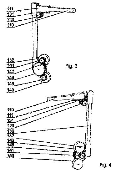


[0030] FIG. 1 shows an overview of a road barrier to which the present invention is applicable. The road barrier comprises supports 101, to which a transverse beam 102 is connected. The supports can have a form of a vertical post anchorable to the ground or a holder fixed to another vertical structure, such as a wall. The beam 102 is connected to the supports 101 via a movable spacer 110 such that upon impact the transverse beam 102 moves towards the support 101.
[0031] FIG. 2 shows the elements of the road barrier according to a first embodiment of the invention in a side view, and FIGS. 3 and 4 show the core elements of that embodiment in a perspective view from the left and right, respectively. Preferably, the core elements are all housed within the support, such as to protect them from external factors, such as dirt, rain or third persons. The movable spacer is coupled, via coupling means 130 in form of a rack 130, with a rotatable energy absorber 140 mounted below the transverse beam 102. As shown in FIG. 2, the rotatable energy absorber 140 can be fixed to the support 101. In particular, the transverse beam 102 can be mounted in the upper portion of the support 101 and the rotatable energy absorber 140 can be mounted in the lower portion of the support 101. The movable spacer 110 drives a transmission 120, which in turn drives a rack 130. The spacer 110 is movable in a first direction and the rack 130 is movable in a second direction tilted with respect to the first direction. Therefore, upon impact, at least part of the energy imparted to the transverse beam 102 in the first direction of the movement of the spacer 110 is passed to the rack 130 movable in the second direction. The rack 130 is coupled at its second end with a rotatable energy absorber 140 with at least one rotor 142, 143 which absorbs in rotational movement at least part of the kinetic energy imparted to the transverse beam 102. The amount of energy accumulated in the rotor 142, 142 in other words a rotatable mass, depends on the weight and the moment of inertia of the rotor, its diameter and rotational speed, which in turn depends on the parameters of the transmission between the beam 102 and the rotor 142, 143. Preferably, the rotors 142, 143 are freewheels.
[0032] The transmission 120 can be a toothed wheel mounted on a shaft attached to the housing of the support 101. The spacer 110 and the rack 130 can be coupled with the transmission 120 via toothed bars 111, 131. The rack 130 can have a toothed bar 132 coupled with a toothed wheel 141 of the rotatable energy absorber 140. However, other types of transmission can be used, such as pneumatic, hydraulic, magnetic, etc.
[0033] The rotatable energy absorber 140 comprises at least one rotor 142, 143, preferably in form of one or more flywheels, mounted on shafts fixed to the support 101. The rotor is coupled with the rack 130 via a transmission which may comprise one or more toothed wheels 144, 145, 146. The movement of the rack 130 induces rotation of the toothed wheels 141, 144, 145, 146 and therefore the rotation of the rotor 142, 143.
[0034] The elements are preferably arranged on two main vertical planes, for example elements 110, 111, 20, 144, 145, 146 are arranged on one main plane and elements 130, 131, 132, 141, 142, 143 are arranged on another main plane. This provides compact size of the energy absorbing mechanism according to the invention and allows to house it within the support 101.
[0035] As shown in FIG. 2, the spacer 110 is configured to move in a substantially horizontal direction and the rack 130 is configured to move in a substantially vertical direction, preferably downwards. Mounting of the rotatable energy absorber 140 below the transverse beam 102 lowers the centre of gravity of the road barrier and increases its stability during impact.
[0036] FIG. 5 shows the operating principle of the road barrier during impact. An impact force imparted to the transverse beam 102 causes movement of the spacer 110 towards the support 101 and, via the transmission 120, movement of the rack 130 downwards. The downwards movement of the rack 130 induces rotation of the at least one rotor 142, 143 of the rotatable energy absorber 140. At least part of the impact energy is therefore converted to the kinetic energy of the rotor 142, 143.
[0037] FIG. 6 shows the elements of the road barrier according to a second embodiment of the invention in a side view. The second embodiment is equivalent to the first embodiment, with the following differences. The spacer 110 may comprise a compressible element 112, such as a spring or a damper. Furthermore, the rack 130 may comprise a compressible element 133, such as a spring or a damper. The compressible elements 112, 133 allow absorbing of a part of energy during the first phase of impact and facilitate inducing the rotation of the rotatable energy absorber 140.
[0038] FIG. 7 shows the elements of the road barrier according to a third embodiment of the invention in a side view. The movable spacer 110 is coupled, via coupling means 150 in form of a strand 150, with a rotatable energy absorber 140 fixed to the support 101 below the transverse beam 102. The strand 150 is connected at a first end 151 to the movable spacer 110 and at a second end 152 to the rotatable energy absorber 140. A roller 153 defines the pathway of the strand 150 along the support 101. Upon impact, at least part of the energy imparted to the transverse beam 102 in the first direction of the movement of the spacer 110 is passed to the strand 150. The second end 152 of the strand 150 is wound around a driving shaft 147 of the rotatable energy absorber 140 such that when impact is imparted to the spacer 110 and the spacer moves into the support, the tension of the strand 150 induces rotation of the driving shaft 147 of the rotatable energy absorber 140 and, consequently, rotation of the toothed wheels 144, 145, 146 and of the rotors 142, 143.
[0039] FIG. 8 shows the elements of the road barrier according to a fourth embodiment of the invention in a side view. The fourth embodiment is equivalent to the third embodiment, with the following differences. The second end 154 of the strand 150 is attached to a toothed bar 154 coupled with a toothed wheel transmission 141 of the rotatable energy absorber 140 such that when impact is imparted to the spacer 110 and the spacer 110 moves into the support 101, the tension of the strand 150 induces, via the toothed bar 154, rotation of the toothed transmission 141 of the rotatable energy absorber 140 and, consequently, rotation of the toothed wheels 144, 145, 146 and of the rotors 142, 143.
[0040] FIG. 9 shows the elements of the road barrier according to a fifth embodiment of the invention in a perspective view. The rotatable energy absorber 140 is fixed to a structure 103 offset horizontally from the support 101, to which the spacer 110 is fixed. The structure 103 can be a ground anchor located aside the post. The structure 103 can be also a neighbouring post, to which the transverse beam 102 is connected. In this embodiment, the coupling means comprise vertical and horizontal coupling, for transferring the energy of impact both in vertical and horizontal direction. The vertical coupling means may have a form of a vertical rotatable shaft 160, preferably housed within the support 101. The first end 161 of the vertical shaft 160 is coupled with the spacer 110 and configured to be induced into rotation upon translational movement of the spacer 110. In one example, the first end 161 of the vertical shaft may be a toothed wheel coupled with a toothed bar at the end of the spacer 110. In another example, as shown in FIG. 9, a strain may be connected between the end of the spacer 110 and wound around a disc mounted at the end 161 of the shaft 160. The horizontal coupling means 170 may have a form of a toothed bar, coupled at one end 171 with a toothed wheel at the second end 162 of the shaft 160 and at another end 172 with the rotor 142. Alternatively, as shown in FIG. 9, the horizontal coupling means 170 may have a form of a strand, wound at one end 171 around the second end 162 of the shaft 160 and at another end 172 around a disc mounted on the shaft of the rotor 142. Horizontally offsetting the rotatable energy absorber 140 from the support 101 allows using various kinds of rotatable energy absorbers 140, which do not have to accommodate within the housing of the support 101. In all embodiments, the rotors of the rotatable energy absorbers may be mounted so as to rotate around a horizontal or vertical axis, depending on the desired configuration.
[0041] FIG. 10 shows the process of manufacturing of the road barrier according to the invention. In steps 301-306 the elements via which the impact energy is transmitted to the rotatable energy absorber are formed, including the rotor formed in step 301, the toothed bars formed in step 303 and the toothed wheels formed in step 305. The elements are manufactured with high degree of precision, such as to allow efficient movement of the elements with limited friction upon impact of forces of large magnitude. The rotor is balanced in step 302 by precise profiling such that it can rotate with high rotational speeds. The teeth of the toothed bars and toothed wheels are hardened in steps 304, 306 such as to withstand large forces and limit the friction between them. The other elements of the road barrier, such as the post and the transverse beam, are formed in step 307 and assembled in step 308. In order to provide high precision of manufacture of the energy absorber and the other components of the road barrier of the invention, the following tools can be used: a water jet cutter, a band saw, welding machines, a standard lathe, a precision lathe, a standard miller, a precision miller, a surface grinder, an external grinder, an internal grinder, a standard drill, a pillar drill, a hydraulic press, a brake press, a bending machine for tubes and sections, a hydraulic bending machine, a belt grinder, a fitter's vice, a compressor, an electro-erosion machine, a hobber, a threader, a welder, cleaning tanks, measurement and control apparatus, a hardening furnace, an electronic balancer, a marking-off table and marking-off tools.
[0042] The road barrier may comprise supports of the first and/or second embodiment, and in addition it may be also supported by other, typical supports. The supports of the first or second embodiment may be installed at places with high impact risk, such as sharp turns, while typical supports may be installed at straight segments of the road.
SHOCK ABSORBING PLATFORM FOR UNLOADING CONTAINERS AT PORTS
A shock absorbing platform for unloading containers at ports, comprising the top plate (1) guided vertically by means of guides (3) and disposed substantially on the same level as the surrounding stage (13) and a shock-absorbing means connected with the plate and comprising kinetic energy absorption rotor arrangements (10), characterized in that it comprises an angular drive train arrangement (7) having an input rod (6) and at least one output rod (8) perpendicular to said input rod (6), wherein the input rod (6) is coupled with the top plate (1) and the output rod (8) is connected to the kinetic energy absorption rotor arrangement (10), comprising at least two serially coupled racks (12, 13, 14) driving the toothed wheel (16, 17, 18), wherein between at least two serially connected racks (12, 13, 14) shock-absorbing means (20); are arranged enabling for relative displacement of the racks (12, 13, 14) in relation to each other.
The present invention relates to a shock absorbing platform for unloading containers at ports, designed to protecting containers or vehicles during loading operation against effects of an excessively rapid drop of the unloaded commodity during unloading operation. Bringing containers down onto sea-platform constitutes a significant problem. Unloading process depends on atmospheric conditions existing on the sea. Strong winds blowing frequently, lateral oscillation caused by a movement of sea-waves or sea-currents result in great losses related with damages of containers hitting sea- platforms. The force of impact of a container against a platform is dependent on an instantaneous weather conditions existing on the sea, and therefore an unloading operation may be impossible during a very short period of time.
For providing shock absorption for containers being brought down, the plates of platforms are supported by means of resilient shock-absorbing arrangements. In different solutions containers in an unload operation are protected by employment of shield elements that are made of elastomeric materials and absorb impacts.
Another system designed for absorbing kinetic energy is disclosed in international patent application WO2004028864 describing a rotor device in which kinetic energy is converted into kinetic energy of rotating masses. In this known solution an element absorbing energy is connected with two toothed bars which by medium of toothed wheels drive kinetic energy rotor accumulators in forms of rods with moveable weights slidably mounted on the rods. An appropriate progressiveness of energy absorption is obtained in this known solution by employment of the moveable weights located as close to the rotation axis of the rotor with the rods as possible in order that a moment of inertia of the rotor in the initial phase of energy absorption be as small as possible. In further movement phase while the rotor starts to rotate, the weights start to translocate under influence of centrifugal force and move away from the rotation axis along the rod axis, until they reach the rod end limiters and in such weight positions the biggest moment of inertia of rotor is achieved that enables for absorption of the increased kinetic energy. International patent application WO2005121593 discloses a device for absorbing and dissipating kinetic energy comprising a beater element cooperating with a rack inducing by means of a toothed wheel a rotational movement of a kinetic energy rotor accumulator, in order to transform impact energy into kinetic energy of rotor accumulator rotational movement.
Such known solutions do not provide high efficiency of a shock absorption for impacts of containers during bringing down operations at different bringing down velocities and different masses. Therefore the object of the present invention is to provide increased efficiency of absorbing and dissipating different and random energy amounts.
A shock-absorbing platform according to the present invention comprises the top plate guided vertically by means of guides and disposed substantially on the same level as the surrounding stage and a shock-absorbing means connected with the plate and comprising kinetic energy absorption rotor arrangements. The solution is characterized in that it comprises an angular drive train arrangement having an input rod and at least one output rod perpendicular to said input rod, wherein the input rod is coupled with the top plate and the output rod is connected to the kinetic energy absorption rotor arrangement, comprising at least two serially coupled racks driving the toothed wheel, wherein between at least two serially connected racks shock- absorbing means are arranged enabling for relative displacement of the racks in relation to each other.
The kinetic energy rotor accumulators preferably have differentiated capability of energy accumulation.
The kinetic energy rotor accumulators preferably have differentiated moments of inertia.
The angular drive train arrangement preferably has a form of a hydraulic T-piece having one input cylinder and at least two output cylinders.
Thanks to embedding shock absorbing elements between at least two serially connected racks, appropriate gaps are formed therebetween, that provides gradual inducing rotational movements of alternate kinetic energy rotor accumulators, and thus in turn it enables for obtaining an abrupt stepped increase of capability of energy absorption. Such a construction enables for adjustment of shock absorbing capability of the platform in dependence of requirements related with differentiated height from which containers drop down onto the platform and with differentiated mass of containers.
Arrangement of shock absorbing elements in front of the alternate racks results in a decrease of impact load acting on cooperating elements during an actuation of alternate kinetic energy rotor accumulators.
Owing to a gradation of moment of inertia of alternate kinetic energy rotor accumulator, in particular when kinetic energy rotor accumulator driving by means of the first rack has smaller moment of inertia than the moment of inertia of kinetic energy rotor accumulator driven by means of the second rack, especially advantageous, smooth and gradual increase of capability of absorbing kinetic energy related with a collision of the container with a platform is achieved. The device arrangement according to the present invention provides high efficiency of kinetic energy absorption during impacts of low kinetic energy as well as during impacts of higher kinetic energy. In the first instance the device according to the present invention provides efficient and very smooth impact energy absorption, as an absorption of kinetic energy of progressive movement takes place with using kinetic energy rotor accumulators of the smallest moment of inertia. In the second instance, the device according to the present invention also provides appropriately efficient and uniform shock-absorption of impact energy, as kinetic energy absorption takes place with using several rotor accumulators of increasing energy absorption capabilities. In case of impacts of greater energy an additional effect occurs in the device according to the present invention consisting in that impact kinetic energy is in a great part accumulated in the rotor accumulators featuring lower energy absorption capability before the rotor accumulators featuring higher energy absorption capability are actuated. Such a sequence of energy absorption provides smoother operation of the device according to the present invention during actuation of next rotor accumulators, even those of the greatest capability of energy absorption featuring the bigger moment of inertia.
The exemplary embodiments of the present invention are schematically presented below in connection with the attached drawings on which:
Fig. 1 presents a side view of a shock absorbing platform according to the present invention during operation of bringing down a container;
Fig. 2 presents the same platform during operation of loading a container onto a transport vehicle, and
Fig. 3 depicts a kinetic energy absorption arrangement.


As presented in the embodiment of Fig. 1 and Fig. 2, the top plate 1 of the platform according to the present invention is connected to a concrete cavity of the stage 2 by means of vertical guides 3 disposed in guiding sleeves 4 in which helical springs 5 are embedded pushing the guides 3 out. Under the central area of the top plate 1 is disposed an output rod 6 of an angular drive train arrangement 7, and each of two output rod 8, oriented perpendicularly relative to the input rod 6, contacts a bumper 9 of kinetic energy absorption rotor arrangement 10. In this embodiment the angular drive train arrangement 7 has a form of a hydraulic T-piece 11 , in which the input rod 6 constitutes the rod of the input piston, and the output rod 8 constitutes the rods of the output pistons. As shown in Fig. 3, the bumper 9 of the kinetic energy absorption rotor arrangement 10 is coupled to three serially connected racks 12, 13, 14. Between the racks 12, 13, 14 and between the bumper 9 and the first rack 12 appropriate gaps are defined enabling appropriate operation of shock absorbing elements 20 and providing a relative displacement of racks 12, 13, 14 relative to each other and between the bumper 9. Each of the racks 12, 13, 14 interengages with a toothed wheel 15 driving a kinetic energy rotor accumulator 16, 17, 18, wherein for achieving greater efficiency of absorbing and dissipating impact energy, the first kinetic energy rotor accumulator 16 driven by the first rack 12 has the smallest moment of inertia, the second kinetic energy rotor accumulator 17 driven by the second rack 13 has the medium moment of inertia, whereas the third kinetic energy rotor accumulator 18 driven by the third rack 4 has the greatest moment of inertia. The bumper 9 is slidably coupled to the side walls of the body plate 19 to which the guide of racks 12, 13, 14 is also attached.
The progressiveness of a characteristic of impact energy absorption may be adjusted by appropriate selection of effective diameters of the driving toothed wheels 15 and by appropriate selection of moments of inertia of alternate kinetic energy rotor accumulators 16, 17, 18.
In the described embodiments unidirectional couplings are also employed, though not presented on the drawing, and arranged between the toothed wheels 15 and kinetic energy accumulators 16, 17, 18. The function of these unidirectional couplings is transferring a torque onto kinetic energy rotor accumulators. After absorption of energy, when angular velocity of the appropriate toothed wheel 15 shall be smaller than angular velocity of corresponding kinetic energy rotor accumulator 16, 17, 18, the unidirectional coupling becomes disconnected thus enabling for unrestricted rotation of the kinetic energy rotor accumulator 16, 17, 18. Energy acting upon the bumper 9 during a drop of a container on the top plate 1 is transferred by medium of the rods 6, 8 of the hydraulic T-piece 11 to the racks 12, 13, 14, and subsequently to kinetic energy rotor accumulators 16, 17, 18. In a result of serial arrangement of the racks 12, 13, 14, a consecutive actuation of kinetic energy rotor accumulators 16, 17, 18 is realized starting from the kinetic energy rotor accumulator 16 of the smallest moment of inertia, and ending with the kinetic energy rotor accumulator 18 of the greatest moment of inertia. In the solution according to the present invention, the maximal idle stroke of the bumper 9 relative to the endmost rack 14 driving the kinetic energy rotor accumulator 18 of the greatest moment of inertia equals the sum of the gaps between the bumper 9 and the first rack 1 and between the racks 12, 13, 14.