Dennis LEE
Pre-Ignition Catalytic Converter
This information is offered for infotainment purposes only. It is not an endorsement or an opinion. Dennis Lee is legendary for alleged scam promotions. The PICC is not yet available, and the HAFC system is "problematic". Caveat emptor...
http://www.preignitioncc.com/FFR/

Welcome to the PICC Revolution in Fuel Economy Technology
The PICC, Pre-Ignition Catalytic Converter is a breakthrough new technology that could get your car up to five times the gas mileage! Its genius is its simplicity. Here’s how it works:
Our scientific testing has led us to believe that the PICC will increase the mileage of all personal vehicles to over 100 miles per gallon (city or highway).
Every car has a Catalytic Converter. The Catalytic Converter that is currently installed on your car is intended to help eliminate pollution and is located in your exhaust pipe. It works by breaking down the large gas molecules that were not burned in your engine and turns them into smaller particles that can be burned in your tailpipe before being released into the air, so less exhaust hits the environment. What if we could turn the gases you are throwing away via your exhaust into added mileage and power for your vehicle?
In other words, what if we “cracked” the gas and broke it down into smaller particles before it went into the engine — not after the engine had wasted it? Everything you would otherwise be throwing away would now be burned IN YOUR ENGINE, providing additional mileage and power! Well, that is what we did! Using a magnetic and electrical reaction to break down the fuel molecules into their elemental state, the PICC creates a plasma, which burns super efficiently and cleanly! Our “Pre-Ignition” Catalytic Converter feeds the engine instead of the environment. So the gasoline you pay for goes further and the exhaust is so negligible it hardly registers.
How To Get Started With Your PICC Conversion Now
The PICC is a customized application which is the second step in a two step process. While the PICC is being developed for your vehicle, the first step to savings can be acquired immediately, so you can begin the process and start increasing your gas mileage right away. Here’s how it works:
The Hydro-Assist Fuel Cell (HAFC) is a kit that is ready to install and give you savings while preparing the way for the PICC Revolution. Since the PICC will use the HAFC to pre-condition the fuel and help turn it into plasma, you can start saving with the HAFC and later upgrade to the completed PICC at your option. The HAFC is an established and proven technology that is already on the market. You may be so happy with the savings you get with the HAFC, you may not even want to upgrade. When you get a PICC Upgrade Quote, we will notify you of your expected increase in savings, and the decision will be yours. The best part is that you get all the savings from driving with the HAFC while you are waiting for even more of an increase in savings with the PICC.
PICC Videos :
http://www.preignitioncc.com/FFR/flashPiccHi.htm
http://www.preignitioncc.com/FFR/flashPiccLo.htm
http://dutman.vo.llnwd.net/o15/piccwin/piccwinhi.wmv
http://dutman.vo.llnwd.net/o15/piccwin/piccwinlo.wmv
HAFC Videos :
http://www.preignitioncc.com/FFR/flashHafcHi.htm
http://www.preignitioncc.com/FFR/flashHafcLo.htm
http://dutman.vo.llnwd.net/o15/hafcwin/winhafchi.wmv
http://dutman.vo.llnwd.net/o15/hafcwin/winhafclo.wmv
http://www.preignitioncc.com/FFR/
The HAFC Hydrogen Fuel Cell / Vaporizer / Optimizer
HAFC Fuel Cell
* 6 x 6 x 4-1/2
* draws 15 amps
* produces 50-70 liters of hydrogen/oxygen mixture per hour
Our new double cell makes twice as much gas.
The Fuel Cell is the heart of the system. It separates water into hydrogen and oxygen, and adds the hydrogen to the fuel mixture, making the fuel burn better so the computer can “lean” the fuel. The unit is built of durable stainless steel. It can be used even in freezing weather.
The HAFC Vaporizer
The Vaporizer contains 4 powerful magnets to help ionize the fuel and make it easier to vaporize for better consumption, a cleaner burn, and a more thorough utilization of the fuel. The radiator hose also provides heat-exchange to pre-heat the gasoline for this process as well.
The HAFC Optimizer
Most cars have computers that govern the gas usage of the vehicle. The HAFC Optimizer is an actual computer that ties into the emissions control system on the car and teaches the manufacturer’s computer to operate the HAFC System to keep it from rejecting the savings. This unit is the patented difference between the HAFC and all other gas saving devices.
http://peswiki.com/index.php/Directory:PICC_Pre-Ignition_Catalytic_Converter
PESWiki Directory :
PICC Pre-Ignition Catalytic Converter
Pre-Ignition Catalytic Converter (PICC) by Better World Technologies, will be available soon, according to the company. Other, interim fuel efficiency technologies are available in the interim, the cost of which will be applied toward the PICC once it is available.
Better World Technologies presents a catalytic converter replacement that pre-treats the fuel for complete combustion, rather than burning what is left over after incomplete combustion. They claim that the technology is legal.
The PICC technology is still in research and development and slated for public debut March 4-6 2008 at the Washington International Renewable Energy Conference (WIREC 2008) in Washington DC. While waiting for its release, Better World Technologies presents several other fuel-saving, emissions-reducing technologies that will improve mileage from between 50% and 100% -- "guaranteed." The Hydro Assist Fuel Cell is available now and will be included in the PICC package. For customers already enjoying increased mileage with the HAFC the cost of that technology will be deducted "100%" toward the purchase of the PICC once it becomes available.
All these systems are sold by United Community Services of America dealers network for Better World Technologies product line...
Visit PESWiki for more details and links to distributors.
Au Contraire :
http://www.electricitybook.com/dennis-lee-scam/
Hydro Boost and Dennis Lee Scam
US
Patent Application 20090038591
Pre-Ignition Fuel Treatment System
February 12, 2009
Abstract -- A method and apparatus for reforming a hydrocarbon fuel increases its energy content, improves its combustibility and reduces combustion by-products. The hydrocarbon fuel is cracked during multiple passes through a reactor vessel by means of electrochemical interactions with a reactor rod composed of a magnetic and/or catalytic material.
Inventors:
Lee; Dennis; (Newfoundland, NJ) ; Holler; Michael; (Honey
Grove, PA)
U.S. Current Class: 123/538; 123/3; 123/557
Intern'l Class: F02M 27/02 20060101 F02M027/02
BACKGROUND OF THE INVENTION
[0002] The present invention improves combustion efficiency and reduces polluting combustion by-products of internal combustion engines by reforming the hydrocarbon fuel to render it more readily and completely combustible. This is accomplished by a pre-ignition fuel treatment system in which large, complex hydrocarbon molecules are "cracked" or broken down into smaller, simpler molecules. These simpler hydrocarbons are more readily combustible and produce fewer combustion by-products. Hydrocarbon "cracking" is a highly endothermic reaction, which means it requires a large amount of energy to complete the reaction. Therefore, hydrocarbon cracking must take place under conditions of high temperature and high pressure. The cracking process is facilitated by the presence of a catalystic material and/or by an electrochemical quasi-catalytic reaction.
[0003] The present invention takes advantage of the high temperature, high pressure environment of the engine's exhaust gases to create a reaction zone in which the hydrocarbon molecules of the fuel are cracked. The hydrocarbon cracking reaction is facilitated by the insertion into the reaction zone of a reactor rod made of a magnetic material, which is preferably iron. Under the high temperature conditions of the reaction zone, the surface of the iron reactor rod becomes oxidized. It is known that iron oxides act as catalysts for various hydrocarbon cracking processes, as for example, in the hydrocarbon reforming processes taught by Setzer, et al., U.S. Pat. No. 4,451,578.
[0004] As ionized fuel molecules and atoms are produced during the cracking process, moreover, their motion around the reactor rod generates an electromagnetic field which magnetizes the iron in the rod. As the iron rod itself magnetizes, the rod generates its own magnetic field, which further ionizes the fuel and accelerates the motion of the ionized particles. These accelerated ions then generate a still stronger electromagnetic field, which in turn induces even greater magnetism in the iron rod. Thus, the electrical-magnetic interaction of the ionized fuel and the reactor rod becomes a feedback loop that drives the process toward ever greater ionization until the complex hydrocarbons in the fuel are broken down into simpler hydrocarbons, which are in a plasma state. This is an electrochemical quasi-catalytic reaction that can proceed even in the absence of a catalytic material in the reactor rod.
[0005] The "Background of the Invention" discussion of application Ser. No. 11/889,226, which is incorporated herein by reference, explains that the prior art patents in this field, and specifically Pantone, U.S. Pat. No. 5,794,601, and Jonson, U.S. Pat. No. 7,194,984, fail to provide the proper environment in the reaction zone to sustain an endothermic hydrocarbon cracking process. An important distinction between the present invention and the Pantone and Jonson patents is the total absence in the prior art of either catalytic reactor rods or an electrochemical quasi-catalytic process. Without such catalytic and/or quasi-catalytic reactions, hydrocarbon cracking simply cannot occur in the temperature range of engine exhaust gases. Consequently, the prior art fails to disclose an apparatus and process capable of cracking hydrocarbon fuel and converting it into a genuine plasma so as to truly improve the fuel's combustibility and increase the overall combustion efficiency of the internal combustion engine in which the fuel is burned.
[0006] The present invention represents an improvement over the "Pre-Ignition Fuel Treatment System" described in application Ser. No. 11/889,226, insofar as it provides for a multi-pass reaction zone. In the previous application, the fuel makes only a single pass through the reaction zone, which results in some portion of the fuel that goes to the engine remaining unreformed. This factor will limit the improvement in fuel efficiency that the invention seeks to achieve.
[0007] In the present invention, however, the fuel is re-circulated through the reaction zone in multiple passes until virtually all of the fuel is reformed. After each pass through the reaction zone, the reformed fuel components will be in a plasma state containing large numbers of anions (i.e., negatively charged ions). In order to stabilize the reformed fuel plasma, hydrogen cations (H.sup.+ ions) are injected downstream of the reaction zone. Still further downstream, the fuel is cooled and condensed, so that the unreformed fuel (e.g., gasoline) will revert to a liquid state, while the reformed fuel components (typically comprising methane, ethane, propane, and butane) remain in a gaseous state.
[0008] The stabilized reformed fuel gas is then stored in an auxiliary fuel tank, while the unreformed liquid fuel is collected in the main fuel tank, from where it is re-circulated back through the reaction zone, and the process is repeated in recurring cycles. From the auxiliary fuel tank, some of the reformed gaseous fuel is pumped to the engine as needed, while some of it is pumped back into the reaction zone to act as a "carrier-gas" into which atomized unreformed liquid fuel is injected. This latter step enables the present invention to avoid injecting air as a carrier-gas for the atomized fuel entering the reaction zone. The present invention thereby averts one of the principal disadvantages of the system disclosed in application Ser. No. 11/889,226, namely the potential for partial combustion of the fuel in the reaction zone due to the presence of oxygen there. Such partial combustion generates pollutants (CO and CO.sub.2) and reduces fuel efficiency. Moreover, the exclusion of air from the reaction zone in the present invention eliminates nitrogen as well as oxygen and thereby prevents the formation of NO.sub.x pollutants.
[0009] Therefore, the present invention represents an improvement over the "Pre-Ignition Fuel Treatment System" described in application Ser. No. 11/889,226 by reforming a greater percentage of the fuel through use of a multi-pass reaction zone, and by eliminating partial fuel combustion and NO.sub.x formation within the reaction zone. The present invention also has the advantage over the prior art of producing a stabilized reformed gaseous fuel that can be stored in an auxiliary fuel tank and used as needed. The prior art, including this inventor's prior application Ser. No. 11/889,226, has no storage capability for reformed fuel and thus requires continuous operation of the fuel treatment system while the engine is running. This is particularly problematic during the initial cold start of an engine and during rapid acceleration, when the output of reformed fuel will not keep pace with the real-time fuel demand of the engine.
[0010] The reformed fuel storage capability of the present invention, on the other hand, allows the fuel treatment system of the current invention to cycle on and off as needed to maintain an adequate reserve of reformed gaseous fuel. Unlike the prior art, the present invention maintains the same high level of fuel efficiency and low level of pollutants during cold engine starting and rapid acceleration.
SUMMARY OF THE INVENTION
[0011] It is an object of the present invention to create a reaction zone in a motor vehicle wherein the hydrocarbon fuel is reformed at high temperature and pressure, such that large hydrocarbon molecules are "cracked" to produce smaller, more readily combustible molecules.
[0012] It is another object of the present invention to take advantage of the high temperature, high pressure environment of the engine's exhaust gases by locating the reaction zone within the exhaust pipe, such that some of the energy of exhaust gases is transferred to the fuel molecules and helps induce molecular cracking.
[0013] It is a further object of the present invention to promote in the reaction zone catalytic and/or electrochemical quasi-catalytic reactions in order to facilitate the hydrocarbon cracking process and to enable that process to take place at a lower temperature and pressure than would otherwise be feasible.
[0014] It is yet another object of the present invention to utilize a reactor rod composed of a material that also has magnetic properties, such that when ions from the cracking process flow around the reactor rod, the rod becomes magnetized and generates a magnetic field which interacts with ionized hydrocarbon molecules, causing them to accelerate.
[0015] It is yet a further object of the present invention to create in the reaction zone a positive feedback loop between the magnetization of the reactor rod and the acceleration of the hydrocarbon molecules, such that the accelerated motion of the ionized molecules induces a progressively stronger magnetism in the rod, which in turn generates a stronger magnetic field that further accelerates the molecules.
[0016] It is still another object of the present invention to utilize the electromagnetic feedback loop created in the reaction zone to accelerate the hydrocarbon fuel molecules to such an elevated energy level that the reformed portion of the fuel is transformed into a plasma.
[0017] It is still a further object of the present invention to crack virtually all of the hydrocarbon fuel molecules by utilizing a multi-pass reaction zone, such that, after each pass through the reaction zone, the treated fuel is cooled and the larger unreformed hydrocarbon molecules condense into a liquid, which is then separated from the smaller reformed hydrocarbon molecules that remain in a gaseous state, with the unreformed liquid fuel being re-circulated back through the reaction zone.
[0018] It is yet one more object of the present invention to produce a stable reformed hydrocarbon fuel, which can be stored and used as needed by the engine, by injecting hydrogen cations (H.sup.+ ions) into the reformed fuel plasma downstream of the reaction zone, so that the hydrogen cations combine with the reformed fuel anions (e.g., CH.sub.3.sup.-, CH.sub.2.sup.-, C.sub.2H.sub.5.sup.-, etc.) to produce stable, neutral molecules of reformed fuel (e.g., CH.sub.4, C.sub.2H.sub.6, etc.).
[0019] It is still one more object of the present invention to avoid the partial combustion of fuel in the reaction zone and the concomitant generation of pollutants (such as CO and NO.sub.x) by excluding air from the reaction zone and instead using a portion of the reformed gaseous hydrocarbon fuel as a "carrier-gas" into which atomized unreformed fuel is injected at the inlet end of the reaction zone.
[0020] These and other beneficial objects are achieved by a process in which a multi-pass reaction zone is established within the outflow of exhaust gases downstream of the exhaust manifold of an internal combustion engine. The reaction zone comprises a reactor vessel that is installed within the exhaust pipe, such that the exhaust gases flow around the reactor vessel on all sides. The reactor vessel is an oblong plenum formed by a rigid reactor enclosure, which is non-contiguously affixed to the exhaust pipe. Within the reactor enclosure is a reactor rod, which is axially positioned within the reactor vessel such that a uniform annular plenum is formed between the surface of the reactor rod and the walls of the reactor enclosure. The reactor rod is centrally located along the length of the reactor vessel, and it is composed of a material that has magnetic properties and preferably has catalytic properties as well.
[0021] On the inlet end of the reactor vessel is an injection assembly, comprising one or more fuel injection ports and one or more carrier-gas injection ports. The fuel injection ports are hydraulically connected to a fuel line, through which a hydrocarbon fuel flows from a main fuel tank. The carrier-gas injection ports are pneumatically connected to an auxiliary fuel tank in which gaseous reformed hydrocarbon fuel is stored.
[0022] Downstream of the outlet end of the reactor vessel is a condenser in which the partially reformed fuel is cooled, thereby causing the larger, unreformed hydrocarbon molecules to condense as a liquid, while the smaller, reformed hydrocarbon molecules remain as a gas. The unreformed liquid fuel then flows into the main fuel tank, from where it is re-circulated back through the reaction zone. Upstream of the condenser, the partially reformed fuel is injected with hydrogen cations so as to convert the reformed fuel plasma into a stable molecular state in order to facilitate storage of the reformed fuel. The stabilized reformed fuel is pumped into the auxiliary fuel tank, which is pneumatically connected to the engine's carburetor and to the carrier-gas injection ports.
[0023] The mixture of unreformed fuel and reformed carrier-gas (hereafter referred to as the "fuel-gas mixture") flows within the reactor vessel in the opposite direction to the flow of exhaust gases around the reactor enclosure. At the distal side of this cross-flow process (i.e., the side furthest from the exhaust manifold), the fuel-gas mixture is heated by the exhaust gases to a temperature at which the unreformed fuel is completely vaporized. The vaporized fuel-gas mixture then encounters the reactor rod at its distal end, which preferably has a convex shape to promote laminar flow around it. As the vaporized fuel-gas mixture enters the annular plenum around the reactor rod, its flow path becomes constricted, which causes its pressure and velocity to increase. The increased pressure and kinetic energy of the vaporized fuel-gas mixture is further augmented by its absorption of thermal energy from the exhaust gases, which are becoming progressively hotter as the exhaust manifold is approached.
[0024] As the temperature and pressure of the vaporized fuel-gas mixture becomes progressively elevated, some of the vaporized unreformed fuel molecules reach a sufficient energy to become ionized and/or to undergo at the surface of the reactor rod catalytic cracking reactions that produce ionized molecules. The motion of the ionized fuel molecules generates an electromagnetic field around the reactor rod, and this electromagnetic field magnetizes the reactor rod itself. As the reactor rod becomes magnetized, it generates its own magnetic field which causes the motion of the ionized fuel molecules to accelerate. The accelerated motion of the ionized fuel molecules has two effects. First, the accelerated ionic flow generates a stronger electromagnetic field around the reactor rod, which causes the reactor rod to become more strongly magnetized, which then further accelerates the ionic flow. Second, the accelerated flow increases the kinetic energy of the unreformed fuel molecules, thereby increasing the temperature and pressure of the vaporized fuel, so that an increasing number of molecules undergo catalytic and/or quasi-catalytic cracking along the surface of the reactor rod.
[0025] The electrochemical quasi-catalytic cracking process occurs as follows: As more fuel molecules ionize and/or crack, more ions are produced and their increasing number and acceleration generates a progressively stronger electromagnetic field around the reactor rod. This strengthening electromagnetic field, in turn, progressively increases the magnetization of the rod. The progressively stronger magnetic field generated by the reactor rod then further accelerates the molecular flow, further increasing the kinetic energy of the molecules and causing more of them to crack and ionize.
[0026] Thus, a positive feedback loop is established which drives the hydrocarbon molecules to progressively higher kinetic energy levels. This is an endothermic process that increasingly draws energy from the cross-flow of exhaust gases as those gases become hotter toward the proximal side of the reactor vessel (i.e., the side closest to the exhaust manifold). This positive feedback loop continues until the vaporized fuel-gas mixture reaches the proximal end of the reactor rod and has been ionized to a degree corresponding to the physical state known as plasma.
[0027] The present invention represents an improvement over the "Pre-Ignition Fuel Treatment System" disclosed in application Ser. No. 11/889,226 in three principal respects:
[0028] (1) Recognizing that all of the hydrocarbon fuel molecules will not be cracked in a single pass through the reaction zone, the present invention provides a multi-pass reaction zone, through which the unreformed fuel molecules are re-circulated in multiple passes as many times as it takes to crack them. This multi-pass system assures that virtually 100% of the hydrocarbon fuel molecules will ultimately be cracked, thereby producing a reformed hydrocarbon fuel comprising smaller molecules (typically methane, ethane, propane and butane) which are more readily combustible and which generate less pollutants when combusted.
[0029] (2) Recognizing that the presence of air in the reaction zone has undesirable consequences, the present invention eliminates the use of air as a carrier-gas for the atomized fuel injected at the inlet end of the reactor vessel and instead uses a portion of the gaseous reformed fuel as a carrier-gas. This airless reaction zone excludes oxygen and nitrogen (except to the extent they are present in the fuel) and thereby prevents the partial combustion of the fuel before it gets to the engine, which reduces overall fuel efficiency. The airless reaction zone also prevents the formation of pollutants such as carbon monoxide, carbon dioxide and oxides of nitrogen.
[0030] (3) Recognizing that direct flow of the reformed fuel from the reaction zone to the engine's intake manifold will be insufficient during cold start-up and rapid acceleration, the present invention stabilizes the reformed fuel, thereby allowing it to be stored for use as needed by the engine.
BRIEF DESCRIPTION OF THE DRAWINGS
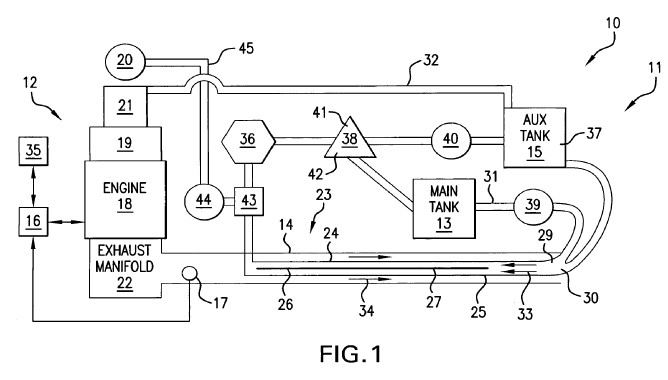
[0031] FIG. 1 is a schematic diagram of the improved pre-ignition fuel treatment system according to the preferred embodiment of the present invention.
[0032] FIG. 2 is a cross-sectional view of the reaction zone with the reactor vessel installed in an exhaust pipe according to the preferred embodiment of the present invention.

[0033] FIG. 3 is a cross-sectional view of an alternate configuration of the reactor rod component of the present invention.

DETAILED DESCRIPTION OF THE PREFERRED EMBODIMENT
[0034] Referring to FIG. 1, an improved pre-ignition fuel treatment system 10 is installed in a motor vehicle 11 having an internal combustion engine 12, a main fuel tank 13, an exhaust pipe 14, an auxiliary fuel tank 15, an engine control module (ECM) 16, and one or more engine/emissions sensor(s) 17. The main fuel tank 13 stores an unreformed hydrocarbon fuel, such as gasoline, that is mixed with a carrier-gas 37 stored in the auxiliary fuel tank 15 to make a fuel-gas mixture 33. Combustion by-products and excess air, collectively referred to as exhaust gases 34, exit from the vehicle to the external atmosphere through the exhaust pipe 14. The engine/emissions sensors 17 monitor the air-to-fuel ratio and/or the amount of oxygen in the exhaust gases 34.
[0035] The engine 12 comprises a combustion zone 18, an intake manifold 19, an air filter 20, an LPG (liquefied petroleum gas) carburetor 21, and an exhaust manifold 22. In the combustion zone 18 a fuel-air mixture is combusted and the exhaust gases 34 are expelled into the exhaust manifold 22, which then expels the exhaust gases 34 into the exhaust pipe 14. The combustion process in the combustion zone 18 has the effect of creating a partial vacuum in the intake manifold 19, which draws air from the external atmosphere into the engine 12 through an air filter 20. The air drawn into the intake manifold 19 is mixed with fuel in the LPG carburetor 21 that is located between the air filter 20 and the intake manifold 19. The air-to-fuel ratio produced by the LPG carburetor 21 is controlled by the ECM 16, which is a microprocessor that computes the optimal air-to-fuel ratio based on the readings of the engine/emissions sensor(s) 17.
[0036] Referring now to both FIG. 1 and FIG. 2, the present invention 10 establishes a multi-pass reaction zone 23 in the exhaust pipe 14 by inserting into a section of the exhaust pipe 14 a reactor vessel 24. The reactor vessel 24 is an oblong plenum formed by a rigid reactor enclosure 25, which is non-contiguously affixed to the exhaust pipe 14. In the preferred embodiment 10, the reactor vessel 24 is a tubular structure fabricated of a material having a high thermal conductivity that can withstand a high temperature, high pressure environment. Optionally, the interior surface of the reactor vessel 24 at its distal end can be textured to increase its area so as to improve heat transfer across the surface. The reactor vessel 24 is axially installed within the exhaust pipe 14 such that the exhaust gases 34 flow around the entire perimeter of the reactor vessel 24. In the preferred embodiment 10, the longitudinal axis of the reactor vessel 24 is aligned with that of the section of exhaust pipe 14 into which it is inserted.
[0037] In addition to the reactor enclosure 25, the reactor vessel 24 comprises a reactor rod 26, an annular plenum 27, and an injection assembly 28. The reactor rod 26 is an oblong structure axially positioned within the reactor enclosure 25, such that the annular plenum 27 is formed between the reactor rod 26 and the reactor enclosure 25. In the preferred embodiment, the reactor rod 26 has an elongated cylindrical shape with a convex distal end (i.e., the end furthest from the exhaust manifold 22) and a concave proximal end (i.e., the end closest to the exhaust manifold 22). The diameter of the reactor rod 26 is such that the width of the annular plenum 27 is approximately 1/16 inch. Optionally, the reactor rod 26, can have a slightly tapered diameter in the midsection of the rod. Also optionally, the reactor rod 26 can have a tapered distal side transitioning into a cylindrical proximal side, with both ends being convex, as shown in FIG. 3. The tapered distal end of the latter reactor rod 26 configuration helps reduce turbulence by facilitating a more gradual acceleration of the fuel-gas mixture 33. The length of the reactor rod 26 is in the range of 4 to 12 inches, depending on the type of fuel and the size of the engine 12.
[0038] The material composition of the reactor rod 26 is crucial importance to the process of cracking the hydrocarbon fuel and transforming it into a plasma. The reactor rod 26 preferably serves the dual roles of providing a catalyst for the cracking process and participating in the "feedback loop" electromagnetic interaction with ionized fuel molecules, as described hereinabove, which drives the fuel-gas mixture 33 toward a plasma state. In order to fulfill both of these roles, the reactor rod 26 must contain materials that are both highly magnetic and good catalysts for the hydrocarbon cracking process. While the preferred embodiment 10 uses an iron reactor rod 26, other suitable material are steel, nickel, cobalt, rare-earth metals, alloys of the foregoing metals, and magnetic ceramics. Nickel, cobalt and rare-earth metals have known applications as catalysts in hydrocarbon cracking, as disclosed in Cornelius et al., U.S. Pat. No. 4,101,376, Sie, U.S. Pat. No. 4,579,986, and Kumar et al., U.S. Pat. No. 5,248,642, respectively. The reactor rod 26 can also consist of a magnetic core with a catalytic coating or plating. For example, a reactor rod 26 with a steel core covered by a layer of platinum plating is also suitable.
[0039] While it is preferable to use a reactor rod 26 having catalytic properties, the present invention 10 does not depend exclusively on a catalytic reactor rod 26. The electrochemical quasi-catalytic reactions promoted by a reactor rod 26 made of a non-catalytic magnetic material are also capable of sustaining the hydrocarbon reformation process.
[0040] The shape of the reactor rod 26 is also plays an important role in the cracking and plasma-formation processes. The distal end of the reactor rod 26 has a convex shape, so that the flow of the fuel-gas mixture 33 around the end of the rod is laminar. The goal in forcing the fuel-gas mixture 33 into the constrained annular plenum 27 is to accelerate the flow rate and thereby increase the velocity and kinetic energy of the fuel molecules so that some of them will attain the energy level needed for ionization and cracking to begin. Therefore, turbulent flow around the reactor rod 26 is to be avoided, since turbulence dissipates the molecular kinetic energy and thus retards the ionization and cracking processes. Accordingly, in the preferred embodiment, the proximal end of the reactor rod 26 has a concave shape, which has the effect of creating an area of reduced pressure downstream of the reactor rod 26. This area of reduced pressure has the effect of drawing the flow of fuel-gas mixture 33 evenly along the surface of the reactor rod 26, so that energy-dissipating areas of turbulent flow are avoided.
[0041] On the distal end of the reactor vessel 24 is the injection assembly 28, comprising one or more fuel injection port(s) 29 and one or more carrier-gas injection port(s) 30. The fuel injection port(s) are hydraulically connected to a fuel line 31, through which the unreformed hydrocarbon fuel is pumped by a primary pump 39 from the main fuel tank 13. The carrier-gas injection port(s) 30 are pneumatically connected to the auxiliary fuel tank 15, in which is stored the gaseous reformed hydrocarbon fuel 37, which serves as the carrier-gas.
[0042] Downstream of the proximal end of the reactor vessel 24, is a condenser 36, in which the fuel-gas mixture 33 is cooled, thereby causing the larger, unreformed hydrocarbon molecules to condense into a liquid phase, while the smaller, reformed hydrocarbon molecules remain in a gaseous phase. The liquid and gaseous phases separate from one another in the liquid-vapor separator 38, which comprises an upper gas chamber 41 and a lower sump chamber 42. The liquid unreformed fuel collects in the sump chamber 42 and is drawn into the main fuel tank 13, which is at lower pressure than the sump chamber 42. The flow of liquid unreformed fuel from the sump chamber 42 to the main fuel tank 13 is controlled by a solenoid valve (not shown) based on the liquid level in the sump chamber 42. From the main fuel tank 13, the unreformed liquid fuel is pumped into the fuel injection port(s) 29 by the primary pump 39, and it is re-circulated through the reactor vessel 24 in multiple passes as many times as it takes to crack it. The reformed gaseous fuel 37 collects in the gas chamber 41, from which a secondary pump 40 pumps it into the auxiliary fuel tank 15.
[0043] Between the reactor vessel 24 and the condenser 36 is a hydrogen-mixing manifold 43, in which hydrogen cations (H.sup.+ ions) are injected into the flow of the fuel-gas mixture 33. The hydrogen cations are generated by an electrolysis cell 44. The hydrogen cations are drawn out of the cathode side of the electrolysis cell 44 by a Venturi injector, which utilizes a partial vacuum created by the flow of the fuel-gas mixture 33 across a Venturi opening or tube. The hydrogen cations combine with the anions of the reformed hydrocarbon fuel plasma to convert the ions into neutral molecules and thereby stabilize the reformed fuel gas. Optionally, the oxygen anions from the anode side of the electrolysis cell 44 can be injected into the engine's air filter 20 through an oxygen inlet 45 in order to improve combustion.
[0044] The stabilized reformed fuel gas 37 is then separated from the unreformed liquid fuel by the condenser 36 and the liquid-vapor separator 38, and then it is pumped into the auxiliary fuel tank 15 by the secondary pump 40. From the auxiliary fuel tank 15, some of the stabilized reformed fuel gas 37 is drawn into the intake manifold 19 of the engine 18 through the vacuum conduit 32. Some of the stabilized reformed fuel gas 37 is also injected into the reactor vessel 24 through the carrier-gas injection port(s) 30.
[0045] In the present invention 10, unlike that disclosed in application Ser. No. 11/889,226, the partial vacuum of the intake manifold 19 need no longer be used to create a pressure drop across the reactor vessel 24. Instead, the primary and secondary pumps 39 40 create the pressure drop needed to maintain the flow of fuel-gas mixture 33 from the distal to the proximal end of the reactor vessel 24.
[0046] The flow direction of fuel-gas mixture 33 through the reactor vessel 24 is in the opposite direction to the flow direction the exhaust gases 34 through the exhaust pipe 14, thus creating a cross-flow that optimizes the transfer to thermal energy from the exhaust gases 34 to the fuel-gas mixture 33. As the fuel-gas mixture 33 is drawn into the reactor enclosure 25 through the injector assembly 28, the cross-flow heats the fuel-gas mixture to the point at which the fuel component is vaporized. As the vaporized fuel-gas mixture 33 enters the annular plenum 27 around the reactor rod 26, its flow path becomes constricted, which causes its pressure and velocity to increase. The increased pressure and kinetic energy of the vaporized fuel-gas mixture 33 is further augmented by its absorption of thermal energy from the exhaust gases, which are becoming progressively hotter as the cross-flow approaches the exhaust manifold 22.
[0047] As the fuel-gas mixture 33 flows through the annular plenum 27, the unreformed fuel component undergoes the process of ionization, cracking and plasma-formation described hereinabove. At the proximal end of the reactor vessel 24, hydrogen cations from the electrolysis cell 38 are injected into the fuel-gas mixture 33 in order to stabilize the reformed fuel molecules. The fuel-gas mixture 33 then flows into the condenser 36, where the unreformed liquid fuel is separated from the stabilized reformed gaseous fuel 37, with the former being pumped to the auxiliary fuel tank 15 and the latter being drawn into the main fuel tank 13.
[0048] The stabilized reformed gaseous fuel 37 is drawn into the intake manifold 19 through the vacuum conduit 32. At this juncture, the engine control module (ECM) 16 will determine the appropriate air-to-fuel ratio, which will be set either richer (lower ratio) or leaner (higher ratio) based on the readings of the engine/emissions monitor(s) 17. Since, the ECM 16 bases its determination of air-to-fuel ratio on the stoichiometry of conventional fuel (gasoline or diesel) combustion, its operations must be modified to account for the higher energy content of the stabilized reformed gaseous fuel 37 generated by the present invention 10. Therefore, the preferred embodiment of the present invention 10 includes an auxiliary microprocessor 35, which interfaces with the ECM 16 so as to adjust the air-to-fuel ratio to reflect the combustion stoichiometry of the reformed gaseous fuel 37.
[0049] An example will illustrate the need for the auxiliary microprocessor 35. Because of the higher energy content of the stabilized reformed gaseous fuel 37, less of it will be consumed to release the same amount of energy as conventional fuel. Therefore, its combustion will consume less oxygen, causing the concentration of oxygen in the exhaust gases 34 to rise. This rise will be reflected in the readings of the engine/emissions sensors 17 and communicated to the ECM 16. Since the ECM 16 does its calculations based on the energy content of conventional fuel, its normal response would be to infer from the rise in oxygen concentration in the exhaust gases that the air-to-fuel ratio is too lean. Therefore, the ECM 16 standing alone would, under the circumstances of this example, signal the engine 12 to increase the concentration of fuel being sent to the combustion zone 18. In so doing, however, the ECM 16 would undo the fuel economy advantage of the stabilized reformed gaseous fuel 37. When the auxiliary microprocessor 35 interfaces with the ECM 16, however, the air-to-fuel ratio is adjusted to account for the higher energy content of the stabilized reformed gaseous fuel 37, thus enabling the present invention 10 to achieve greater savings in fuel consumption.
[0050] While this invention has been described with reference to a specific embodiment, the description is not to be construed in a limiting sense. Various modifications of the disclosed embodiment, as well as other embodiments of the invention, will be apparent to persons skilled in the art upon reference to this description. It is therefore contemplated that the appended claims will cover any such modifications or embodiments that fall within the true scope of this invention.
http://appft1.uspto.gov/netacgi/nph-Parser?Sect1=PTO2&Sect2=HITOFF&p=1&u=%2Fnetahtml%2FPTO%2Fsearch-bool.html&r=2&f=G&l=50&co1=AND&d=PG01&s1=%22Pre-Ignition+Fuel+Treatment+System%22.TTL.&OS=TTL/%22Pre-Ignition+Fuel+Treatment+System%22&RS=TTL/%22Pre-Ignition+Fuel+Treatment+System%22
US Patent
Application 20080041350
Pre-Ignition
Fuel Treatment System
Lee; Dennis
February 21, 2008
Abstract -- A method and apparatus for reforming a hydrocarbon fuel increases its energy content, improves its combustibility and reduces combustion by-products. The hydrocarbon fuel is cracked and ionized in a reactor vessel by means of a feedback loop of electro-chemical interactions with a reactor rod composed of a magnetic and catalytic material.
US
Patent 7,389,753
System and Process for Improving Engine
Performance
June 24, 2008
Abstract -- An integrated system and process for improving internal combustion engine performance consists of four components: (1) an acetone-based fuel additive phase, (2) a fuel pre-heating and polarization phase, (3) an ionized hydrogen-oxygen plasma injection phase, and (4) a microprocessor-ECM interface phase to optimize the combined performance of the other three components.
BACKGROUND OF THE INVENTION
This invention relates to an integrated system and process for improving the performance of internal combustion engines. Combustion efficiency is increased and exhaust emissions are reduced by the combined effects of: (1) introducing an acetone-based fuel additive in the fuel tank. (2) pre-heating and polarizing the fuel, and (3) mixing a plasma of ionized hydrogen and oxygen with the intake air. This integrated system and process produces synergistic fuel additives with superior combustion characteristics.
With respect to the first component of the present invention, the use of acetone-based fuel additives to improve fuel efficiency is known in the prior art. One example of such a fuel additive is disclosed in Smith, U.S. Pat. No. 6,123,742. Acetone acts as a surfactant with respect to gasoline, reducing the surface tension of the liquid fuel so that it forms finer droplets that vaporize more readily. In the Smith patent disclosure, as in the present invention, acetone is mixed with xylene, the latter being an aromatic hydrocarbon which boosts the fuel's octane rating.
The acetone-based fuel additive component of the present invention differs from those disclosed in the prior art because it is formulated specifically to work in concert with the other two components of this invention. The composition of the additive and the ratio of its fuel mixture are optimized to complement the other fuel enhancement features of this invention.
With respect to the second component of this invention, a number of fuel preheaters are disclosed in the prior art, including Zabenskie, U.S. Pat. No. 4,015,567; Laramee, U.S. Pat. No. 4,527,533; Favreau et al., U.S. Pat. No. 4,841,943; Ray, U.S. Pat. No. 4,846,137; Huang, U.S. Pat. No. 4,984,555; and Lambert, Sr., et al, U.S. Pat. No. 5,118,451. These preheaters operate on the basis of a heat-exchange process between the fuel and hot-water side of the engine cooling system, as does the present invention. The prior art fuel preheaters in some instances produce a super-heated fuel (e.g., Favreau, et al.) and in other instances a vaporized fuel (e.g., Lambert, Sr., et al.). But none of the prior art devices produce a polarized preheated fuel, as does the present invention. The effect of the second component of the present invention is not only to preheat the fuel, but also to polarize the fuel's covalent hydrocarbon bonds, thereby rendering the hydrocarbon molecules more rapidly and completely combustible.
With respect to the third component of this invention, the prior art encompasses several devices for generating gaseous hydrogen-oxygen mixtures to be mixed with fuel prior to combustion. Examples are Ross, U.S. Pat. No. 7,143,722, Larocque, U.S. Pat. No. 6,311,648 and DeSouza, Pub. No. U.S. 2001/0003276. These devices all use an electrolysis cell to electrolyze water into hydrogen and oxygen.
In the electrolysis process, positively-charged hydrogen ions are generated at the cathode, while negatively charged oxygen ions are generated at the anode. In the prior art electrolysis devices, however, no effort is made to retain the ionized state of the generated gases, which simply revert to molecular hydrogen H.sub.2 and oxygen O.sub.2. Consequently, these devices fail to take advantage of the superior combustion characteristics of an ionized hydrogen-oxygen mixture.
In the present invention, on the other hand, the ionized H.sup.+/O.sup.- plasma is not mixed with the fuel, but instead it is drawn from an electrolysis cell directly into the engine's air intake manifold by a Venturi injector. Consequently, the gaseous hydrogen and oxygen remain in an ionized state when they mix with the atomized fuel at the fuel injection ports. Since the fuel itself has already been polarized by the second component of this invention, moreover, the resulting air-fuel mixture is a highly combustible blend of ionized hydrogen-oxygen plasma and enhanced, pre-heated polarized fuel.
Consequently, the present invention presents a unique combination of synergistic fuel additives, fuel pre-heating, fuel polarization, and ionized hydrogen-oxygen injection. The overall result is an ionized gaseous plasma containing enhanced fuel which, when introduced into the engine's cylinders, combusts within optimum efficiency, both maximizing energy recovery and minimizing polluting residuals.
SUMMARY OF THE INVENTION
It is an object of the present invention to maximize the fuel energy efficiency of internal combustion engines while simultaneously minimizing combustion residuals that cause harmful emissions.
It is another object of the present invention to increase internal combustion engine efficiency by recovering waste heat from the engine cooling system and using that heat to pre-heat the fuel so as to make it more readily combustible.
It is yet another object of the present invention to further improve the combustibility of the fuel by passing it through an annular array of magnets during the preheating process in order to polarize the fuel, thereby weakening its covalent bonds and rendering the fuel more readily combustible.
It is a further object of the present invention to inject directly into the engine's intake manifold ionized hydrogen and oxygen gases generated by the electrolysis of water, and to have the ionized H.sup.+/O.sup.- plasma mix with the atomized polarized fuel downstream of the fuel injectors to produce a highly combustible combination of hydrogen-oxygen plasma and enhanced, pre-heated polarized fuel.
It is yet a further object of the present invention to introduce an acetone-based additive to the fuel in a vehicle's fuel tank, with the additive being so formulated and so proportioned to the fuel as to render the fuel more tractable to the pre-heating, polarization and plasma injection processes.
These and other beneficial results are achieved through a three-stage fuel enhancement process, comprising:
1. An acetone-based fuel additive stage,
2. A fuel preheating and polarization stage, and
3. An ionized hydrogen-oxygen plasma injection stage.
The fuel additive stage is implemented by introducing an acetone-based fuel additive directly into a vehicle's tank. By reducing the surface tension of the liquid fuel, the acetone in the additive enables the fuel to atomize into finer droplets and to vaporize more readily. Inclusion of xylene in the additive works to weaken the covalent hydrocarbon bonds of the fuel. Thus the fuel is pre-conditioned and rendered more tractable to the subsequent preheating and polarization stage.
In the preferred embodiment of the present invention, the fuel additive comprises equal volumes of three constituents: acetone, xylene and a conditioning lubricant. The xylene boosts the fuel's octane rating and thus improves engine performance. The conditioning lubricant, which serves to protect the engine and further condition the fuel, comprises, by volume: one part Accelerator.TM. octane booster; one part Energy Release.TM. cylinder coating; three parts GP-7 two-cycle auto racing oil, and three parts Lucas.TM. auto racing oil. The additive is mixed with fuel in the vehicle's fuel tank at a ratio of 3 fluid ounces of additive to 10 gallons of fuel.
The fuel preheating and ionization stage utilizes a heat-exchanger manifold which is installed in the hot-water side of the engine cooling system, typically upstream of the radiator. The heat-exchanger manifold comprises an inner sleeve, through which the fuel flows, and an outer sleeve, through which or along which the hot engine coolant circulates, thereby transferring heat to the fuel. The inner sleeve comprises a series of interconnected annular or tubular magnets, such that the fuel flows through the apertures of the magnets and is polarized by the magnetic field. The heated and polarized fuel then flows from the heat-exchanger manifold into the fuel injectors, where it is atomized and injected into the airflow to the engine cylinders at the fuel injection ports.
The ionized hydrogen-oxygen fuel enhancement stage utilizes an electrolysis cell, preferably of the type disclosed in the patents of Yull Brown, U.S. Pat. Nos. 4,014,777 and 4,081,656, to generate a plasma consisting of two parts H.sup.+ ions to one part O.sup.- ions. The hydrogen-oxygen plasma is drawn out of the electrolysis cell by a Venturi injector, which utilizes a partial vacuum created by the flow of intake air across a Venturi opening or tube. An microprocessor optimizer is used in conjunction with the vehicle's engine and emissions sensors to set the air-to-fuel ratio in order to adjust for the increased energy content of the enhanced fuel-plasma mixture.
As a result of the process and associated apparatus of this invention, the fuel injectors receive an additive-conditioned preheated polarized fuel with optimal atomization/vaporization characteristics, and inject it into an intake airflow containing ionized hydrogen and oxygen plasma. This highly combustible mixture is fed to the engine cylinders at the optimal air-to-fuel ratio set by the optimizer.
BRIEF DESCRIPTION OF THE DRAWINGS
FIG. 1 is a flow chart illustrating the process of the preferred embodiment of the present invention.

FIG. 2 is a perspective exploded view of the heat-exchanger manifold according to the preferred embodiment of the present invention.

FIGS. 3A and 3B are, respectively, lateral and transverse cross section views of the heat-exchanger manifold according to the preferred embodiment of the present invention.

DETAILED DESCRIPTION OF THE PREFERRED EMBODIMENT
Referring to FIG. 1, the preferred embodiment of the present invention 10 is designed to be implemented and installed in a motor vehicle having an internal combustion engine 11, a fuel tank 12, a fuel pump 13, a water pump 14, a radiator 15, an exhaust manifold 16, one or more engine/emissions sensors 17, and a catalytic converter 18. Comprising the engine 11 are a throttle plate 19, a plurality of cylinders 20, a plurality of fuel injectors 21, a plurality of injection ports 22, an intake manifold 23, and an engine control module (ECM) 24.
In the conventional functioning of the engine 11, fuel from the fuel tank 12 is pumped by the fuel pump 13 to the fuel injectors 21. The fuel injectors 21 atomize the fuel and periodically dispense it in discrete pulses through the injection ports 22 into an airflow that enters the engine through the intake manifold 23 under the regulation of the throttle plate 19. The resulting air-fuel mixture is then drawn into multiple intake valves 25, through which the air-fuel mixture passes into the cylinders 20 and is combusted. The air-to-fuel ratio of the mixture is regulated by the duration of the fuel injection pulses, which is in turn controlled by the ECM 24 based on monitoring of oxygen levels in the exhaust manifold 16 upstream of the catalytic converter 18 by the engine/emissions sensors 17.
An acetone-based fuel additive 26 is introduced directly into the fuel tank 12, preferably at a ratio of 3 fluid ounces of additive to 10 gallons of fuel. Preferably, the fuel additive 26 comprises equal volumes of acetone, xylene and a conditioning lubricant. By volume, the conditioning lubricant component consists of one part Accelerator.TM. octane booster, one part Energy Release.TM. cylinder coating, three parts GP-7 two-cycle racing oil, and three parts Lucas.TM. racing oil.
From the fuel tank 12, the additive-conditioned fuel passes through a heat-exchanger manifold 27, which is installed on the hot-water side of the engine's cooling system, typically in or on a section of radiator hose 28 upstream of the radiator 15. The heat-exchanger manifold 27 can be installed alternately either within the upstream section of radiator hose 28 or on its outer surface. Referring to FIGS. 2, 3A and 3B, the heat-exchanger manifold 27 comprises an inner sleeve 29, through which the fuel flows, and an outer sleeve 30, through which or across which hot engine coolant circulates and thereby transfers heat to the fuel. In the alternative embodiment, in which the heat-exchanger manifold 27 is attached to the outer surface of the upstream section of radiator hose 28, heat is transferred from the hot engine coolant to the outer sleeve 30 through the radiator hose 28.
The inner sleeve 29 comprises a series of interconnected annular or tubular magnets 31, such that the fuel flows through the apertures 32 of the magnets 31 and is polarized by the magnetic field. The heated and polarized fuel then flows from the heat-exchanger manifold 27 into the fuel injectors 21, where it is atomized and injected into the gases drawn into the intake manifold 23.
The electrolysis cell 33 generates a plasma consisting of two parts H.sup.+ ions to one part O.sup.- ions. The hydrogen-oxygen plasma is drawn out of the electrolysis cell by a Venturi injector 34, which utilizes a partial vacuum created by the flow of intake air across a Venturi opening or tube. A microprocessor optimizer 35 interfaces with the vehicle's engine/emissions sensors 17 and ECM 24 to control the pulse duration of the fuel injectors 21 so that the air-to-fuel ratio is adjusted for the increased energy content of the enhanced fuel-plasma mixture. This function of the optimizer will typically result in a leaner air-to-fuel ratio than would otherwise be imposed by the ECM 24 alone as dictated by its default settings.
As a result of the process and associated apparatus of this invention, the cylinders 20 receive the pre-heated, polarized, additive-conditioned fuel optimally atomized and mixed with ionized hydrogen-oxygen plasma, such that the combustion efficiency is maximized and residual pollutants are minimized.
While this invention has been described with reference to a specific embodiment, the description is not to be construed in a limiting sense. Various modifications of the disclosed embodiment, as well as other embodiments of the invention, will be apparent to persons skilled in the art upon reference to this description. It is therefore contemplated that the appended claims will cover any such modifications or embodiments that fall within the true scope of this invention.