Xiaodong
LI, et al.
Cotton Carbon Supercapacitor
Cotton Carbon Supercapacitor
http://www.ideaconnection.com/new-inventions/cotton-super-capacitors-05914.html
May-29-12
Cotton
Super Capacitors
A new conductive cotton fabric able to store energy could help power the new generation of flexible electronics and medical implants.
Xiaodong Li, a mechanical engineering professor at the University of South Carolina, created the highly conductive cotton by soaking a $5 cotton T-shirt in a sodium fluoride solution for an hour and then drying it at two different levels of heat, which changed the cotton to activate carbon. The still-flexible material was then coated with a nano-layer of metal manganese oxide, transforming the fabric to a super capacitor with 97.3 percent retention.
The process is inexpensive and eco-friendly, costing up to 10 times less than processing coal or petroleum into activated carbon.
http://news.discovery.com/tech/cotton-t-shirt-battery-120525.html
May 25
Wearable
Energy: T-Shirts Could Charge Phones
New tech could allow your clothes to do double duty.
By Alyssa Danigelis
New tech could allow your clothes to do double duty.
By Alyssa Danigelis
THE GIST
* Using a simple process, University of South Carolina engineers baked a cotton T-shirt into activated carbon.
* By adding a thin conductive metal layer, they created a stable, high performing super capacitor.
* The engineers envision using cotton for energy storage in flexible electronics, roll-up displays, and implanted medical devices. Cotton T-shirts of the future could do double duty by keeping people cool and dry while at the same charging their phones. Click to enlarge this image.
One day, donning a T-shirt could mean you're also sporting a smart device charger. Engineers have successfully transformed cotton into a flexible, highly conductive component, which means it could charge devices.
"In the future, you can imagine our cell phones will be just like a piece of paper you can roll up. But we need to have a flexible energy device to integrate with flexible, stretchable motherboards," said Xiaodong Li, a mechanical engineering professor at the University of South Carolina who led the development with postdoc Lihong Bao. Their article was just published in the journal Advanced Materials (abstract).
Li knows how to be creative with cotton T-shirts. In 2010, he and his colleagues converted one into lightweight body armor by converting the fabric into boron carbide nanowires. So when he began looking for a backbone to make a flexible energy storage device, he turned to a $5 cotton tee from Wal-Mart.
The engineers had to make the cotton highly conductive so they tried several "recipes," Li said. He compared their experiments with trying to replicate a restaurant meal at home without having seen the chef's preparations. First they dipped the cotton in a sodium fluoride solution for an hour, took the wet material and dried it in a preheated oven for three hours. Then they heated it in a hotter furnace for an hour.
By the time it was done, the cotton had changed into activated carbon. Despite being baked, the charred-looking material could still be folded. From there, the engineers coated it with a nano-layer of the conductive metal manganese oxide for the last stage of building their energy storage device. The device, called a super capacitor, is able to respond more quickly than a battery to power needs.
Lead researcher Xiaodong Li said his team knew that future body armor would need a flexible power source. And because the scientists work in South Carolina, which used to have a big cotton industry, they thought, 'Why not use a cotton T-shirt as the energy device?'?
Li on his A-Ha! Moment
Although others have used cotton in devices, Li said that to the best of his knowledge his research group is the first to activate a cotton T-shirt and build it into a super capacitor. Their device's performance is on par with other carbon-based super capacitors, according to their testing. After 1,000 cycles it had 97.3 percent retention.
"This is a very simple low-cost process, and it's green," Li said. In addition to starting with a renewable plant-based material, he and his research group estimate that using cotton directly from textile mills could be as much as 10 times cheaper than chemically processing coal or petroleum into activated carbon.
To take his concept to market, the process needs to be scaled up. Li said that for this next phase, he's looking for a potential industry partner. He's also reaching out to state government leaders about using this process to help revive local textile production.
http://onlinelibrary.wiley.com/doi/10.1002/adma.201200246/abstract;jsessionid=6FE1B6143A1FC47BF9AABB1FD4A93CC0.d01t02
A simple chemical activation route is developed to convert insulating cotton T-shirt textiles into highly conductive and flexible activated carbon textiles (ACTs) for energy-storage applications. Such conversion gives these ACTs an ideal electrical double-layer capacitive behavior. The constructed asymmetric supercapacitors based on the ACTs and MnO2/ACT composite show superior electrochemical performances.
CN102206090
Production method of carbon/silicon carbide (C/SiC) composite material
Production method of carbon/silicon carbide (C/SiC) composite material
Abstract
The invention discloses a production method of a carbon/silicon carbide (C/SiC) composite material. The method comprises the following steps: (1) after carrying out surface treatment on a carbon-fiber three-dimensional felt body or three-dimensional knitted body, and successively carrying out divinylbenzene modified polymethylsilane (PMS) vacuum impregnation and pressurizing impregnation; (2) solidifying the carbon-fiber three-dimensional felt body or three-dimensional knitted body impregnated with the divinylbenzene modified PMS under the vacuum condition; (3) circularly carrying out vacuum impregnation, pressurizing impregnation and vacuum solidification for 1-3 times in turn; (4) sintering an intermediate product obtained in the step (3) in a high-temperature furnace; (5) circularly carrying out vacuum impregnation, pressurizing impregnation, solidification and sintering for 2-6 times in turn according to the rated conditions of the steps (1), (2) and (4); and (6) machining the product treated in the step (5). The ceramic-based composite material produced by the method can be used for manufacturing aerospacecrafts, heat-resisting parts of aircraft engines, various high-speed brake pads and the like.
US2012213995
Flexible Zn2SnO4/MnO2 Core/Shell Nanocable - Carbon Microfiber Hybrid Composites for High Performance Supercapacitor Electrodes
Flexible Zn2SnO4/MnO2 Core/Shell Nanocable - Carbon Microfiber Hybrid Composites for High Performance Supercapacitor Electrodes
Abstract -- Methods for forming hybrid nanowires are provided via forming a plurality of conductive nanowires extending radially from a surface of a flexible microwire; and then forming a thin film shell layer around the conductive nanowires. The conductive nanowires can include a metal oxide, and the thin film shell layer can include a transition metal oxide. Prior to forming the plurality of conductive nanowires, a catalyst coating layer can be formed on the surface of the carbon microfiber. Hybrid structures are also provided, which can include a flexible microwire defining a surface; a plurality of conductive nanowires extending radially from the surface of the flexible microfiber; and a thin film shell layer surrounding each conductive nanowire.
BACKGROUND
[0003] To meet urgent needs for sustainable and renewable power sources in modern electronic industry, many efforts have been made in developing flexible, lightweight and environmentally friendly energy storage devices, such as supercapacitors and batteries. Supereapacitors, also called ultracapacitors, electrochemical capacitors (ECs), or electrical double layer capacitors (EDLCs), have become some of the most promising candidates for next-generation power devices because of their high power density, fast charging/discharging rate, sustainable cycling life (millions of cycles), and excellent cycle stability. Carboneous materials, such as carbon nanotube networks, graphene nanosheets, conducting polymers, transition-metal oxides, and hybrid composites have been used to fabricate flexible supercapacitor electrodes. Among these candidated electrode materials, MnO2 exhibits many intriguing characteristics, such as low cost, environmental friendness, and natural abundance, suggesting it as the most promising electrode material for next generation supercapacitors.
[0004] The theoretical specific capacitance of MnO2 is 1370 F/g. However, due to its poor electric conductivity (10<-5>-10<-6 >S/cm) such high theorectical capacitance has not been achieved in experiments. Some high performance results have been reported only from nanometer-thick MnO2 thin films and/or nanosized MnO2 particles. In addition, when the loading of MnO2 is in a high weight percentage in the electrode, the MnO2 is densely packed and thus has only very limited accessible surface area for participating electrochemical charge storage process, which remarkabley increases the contact resistance and in turn decreases the specific capacitance.
[0005] One promising approach to realizing the practical application of MnO2 and improving its electrical conductivity is to incorporate MnO2 nanostructures or nanometer-thick thin films into carbon-based materials, such as carbon nanotube networks, graphene sheets, and conductive polymers. Recently, Km et at. demonstrated an improved electrochemical capacitive behavior by coating MnO2 onto SnO2 nanowires grown on stainless steel substrate, neverthless, the inflexible/rigid nature of stainless steel substrate prevents them from practical applications in harsh environments such as folding/twisting conditions.
[0006] Therfore, a need exists for methods and materials that can maximize utilization of the pseudocapacity of MnO2, while keeping its thin film morphology and providing reliable electrical connection when designing high performance electrodes for MnO2-based electrochemical supercapacitors.
SUMMARY
[0007] Objects and advantages of the invention will be set forth in part in the following description, or may be obvious from the description, or may be learned through practice of the invention.
[0008] Methods are generally provided for forming hybrid nanowires. For example, a plurality of conductive nanowires can be formed to extend radially from a surface of a flexible microwire (e.g., a carbon microwire). The conductive nanowires can generally include a metal oxide (e.g., Zn2SnO4, ZnO, SnO2, In2O3, indium tin oxide, or combinations thereof). Then, a thin film shell layer can be formed around the conductive nanowires. The thin film shell layer can generally include a transition metal oxide (e.g., MnO2).
[0009] In certain embodiments, prior to forming the plurality of conductive nanowires extending radially from the surface of the flexible substrate, a catalyst coating layer can be formed on the surface of the carbon microfiber. For example, the catalyst coating layer can include gold.
[0010] Forming the thin film shell layer around the conductive nanowires can be achieved, in one embodiment, via forming a precusor solution comprising Na2SO4 and KMnO4; and then immersing the conductive nanowires into the precursor solution.
[0011] Hybrid structures are also generally provided. For example, the hybrid structure can include a flexible microwire (e.g., a carbon microwire) defining a surface; a plurality of conductive nanowires extending radially from the surface of the flexible microfiber; and a thin film shell layer surrounding each conductive nanowire. As with the methods discussed above, the conductive nanowires can include a metal oxide (e.g., Zn2SnO4, ZnO, SnO2, In2O3, indium tin oxide, or combinations thereof), and the thin film shell layer can include a transition metal oxide (e.g., MnO2). In one particular embodiment, a catalyst coating layer (e.g., gold) can be present on the surface of the carbon microfiber.
[0012] Other features and aspects of the present invention are discussed in greater detail below.
BRIEF DESCRIPTION OF THE DRAWINGS
[0013] A full and enabling disclosure of the present invention, including the best mode thereof to one skilled in the art, is set forth more particularly in the remainder of the specification, which includes reference to the accompanying figures, in which:
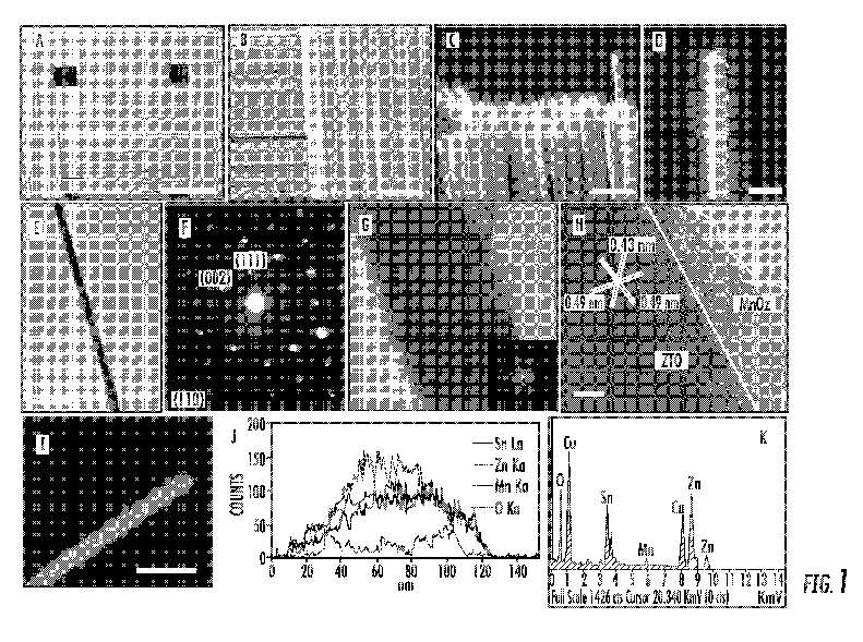
[0014] FIG. 1 shows the structural characterization of an exemplary MnO2/ZTO/CMF hybrid composite: (a, b, c, d) SEM images of ZTO nanowires grown radially on the woven CMFs; (e) TEM image of a MnO2 coated ZTO nanowire; (f) Corresponding SAED pattern; (g) HRTEM image of an individual ZTO/MnO2 nanocable, showing that the rough and thin amorphous layer on the surface of the nanowire is amorphous MnO2 shell, inset is the corresponding FFT pattern; (h) Lattice-resolved HRTEM image of the ZTO/MnO2 core/shell nanocable, showing the detailed interface of crystalline ZTO core and amorphous MnO2 shell; (i, j) TEM image and line-scan profiles (indicated by a line in panel i) of the ZTO/MnO2 core/shell nanocable, showing Zn, Sn, O and Mn elemental profiles; (k) A representative EDS spectrum taken on the nanowire. Scale bars in (a)-(d), (e) , (g), (h) and (i) are 1 mm, 50 [mu]m, 100 [mu]m, 20 [mu]m, 200 nm, 10 nm, 5 nm and 200 nm, respectively.
[0015] FIG. 2 shows: (a, b, c) Cyclic votalmmetry (CV) curves of the MnO2/ZTO/CMF, MnO2/CMF, and ZTO/CMF composites at different scan rates in 1 M Na2SO4 aqueous solution, respectively, showing the high electrochemical performance of the MnO2/ZTO/CMF hybrid composite in comparison with that of MnO2/CMF and ZTO/CMF composites. (d) Specific capacitances of the MnO2/ZTO/CMF (blue), MnO2/CMF (red), and ZTO/CMF (black) composites at different scan rates derived from cyclic votalmmetry.

[0016] FIG. 3 shows: Galvanostatic (GV) constant-current charge/discharge performance of MnO2/ZTO/CMF hybrid composite electrode. (a) Constant-current charge/discharge curves of the MnO2/ZTO/CMF hybrid composite electrode at different current densities. (b) Specific capacitances of of the MnO2/ZTO/CMF hybrid composite at different current densities. (c) Ragone plot of the estimated specific energy and specific power at various charge/discharge rates (current densities). (d) Charge/discharge cycling test at the current density of 10 A/g, showing 1.2% loss after 1000 cycles and inset are the galvanostatic charge/discharge cyclic curves of the first and last 10 cycles.

[0017] FIG. 4 shows: (a) Nyquist plot of the electrochemical impedance spectra (EIS) of MnO2/ZTO/CMF (black squares), MnO2/CMF (red circles), and ZTO/CMF (blue triangles) composites based on the inset equivalent circuit models. (b) The equivalent circuit diagram of different elements from the EIS analysis.

[0018] FIG. 5 shows a general schematic of an exemplary flexible microwire having a plurality of conductive nanowires extending radially from its surface.

[0019] FIG. 6 shows a general schematic of a hybrid structure having a thin film shell layer surrounding each conductive nanowire extending radially from a surface of a flexible microwire.

DETAILED DESCRIPTION OF INVENTION
[0020] The following description and other modifications and variations to the present invention may be practiced by those of ordinary skill in the art, without departing from the spirit and scope of the present invention. In addition, it should be understood that aspects of the various embodiments may be interchanged both in whole or in part. Furthermore, those of ordinary skill in the art will appreciate that the following description is by way of example only, and is not intended to limit the invention.
[0021] In the present disclosure, when a layer is being described as "on" or "over" another layer or substrate, it is to be understood that the layers can either be directly contacting each other or have another layer or feature between the layers, unless expressly stated to the contrary. Thus, these terms are simply describing the relative position of the layers to each other and do not necessarily mean "on top of since the relative position above or below depends upon the orientation of the viewer.
[0022] Chemical elements are discussed in the present disclosure using their common chemical abbreviation, such as commonly found on a periodic table of elements. For example, hydrogen is represented by its common chemical abbreviation H; helium is represented by its common chemical abbreviation He; and so forth.
[0023] As used herein, the prefix "nano" refers to the nanometer scale (e.g., from about 1 um to about 999 nm). For example, wires having an average diameter on the nanometer scale (e.g., from about 1 nm to about 999 nm) are referred to as "nanowires". On the other hand, wires having an average diameter of greater than 1,000 nm (i.e., 1 [mu]m) are generally referred to as "microwires", since the micrometer scale generally involves those materials having an average size of greater than 1 [mu]m.
[0024] Methods are generally provided for the design and fabrication of a hybrid nano/micro-architecture by facile coating ultra-thin (several nanometers thick) MnO2 films to highly electrical conductive metal oxide (e.g., ZTO) nanowires grown radially on flexible microfibers (e.g., carbon microfibers) to achieve high specific capacitance, high energy density, high power density, and long-term life for supercapacitor electrode applications. Such hybrid composites with hierarchical architecture are very promising for next generation high performance flexible supercapacitors.
[0025] Referring to FIG. 5, an exemplary schematic is generally shown of a flexible microfiber 12 having a plurality of conductive nanowires 14 grown radially from its surface 13. As shown, each of the conductive nanowires 14 generally extends in a direction away from the surface 13 of the flexible microfiber 12 to define an individual conductive nanowire. In one particular embodiment, each conductive nanowire 14 can include a metal oxide, such as a zinc tin oxide ("ZTO"). Additionally, the surface 13 of the flexible microfibers 12 can have a catalyst coating layer (e.g., gold) that can serve as a catalyst seed for the formation of the conductive nanowires 14 extending from the flexible microfibers 12.
[0026] FIG. 6 shows an exemplary schematic of a hybrid structure 10 having a plurality of conductive nanowires 14 grown radially on the surface 13 of the carbon microfiber 12, as in FIG. 5, where a shell thin film layer 16 has been formed around each conductive nanowire 14. In one particular embodiment, the shell thin film layer 16 generally includes a transition metal oxide, such as MnO2.
[0027] In one particular embodiment, the crystalline ZTO nanowires grown radially on CMFs can serve as highly conductive cores to support the redox ative MnO2 shells wth highly electrolytic accessible surface areas and to provide reliable electrical connections to the MnO2 shells.
[0028] Each of the flexible microfibers 12, the conductive nanowires 14, and the thin film shell layer 16 are discussed in greater detail below.
[0029] I. Flexible Microfibers
[0030] Any suitable flexible microfiber can serve as the flexible substrates for synthesizing metal oxide conductive nanowires, particularly with assistance of catalyst coating layer present on its surface. In one particular embodiment, the flexible microfiber can generally be a carbon microfiber, such as those generally composed mostly of carbon atoms, with hydrogen and nitrogen atoms sometimes present. The carbon atoms are generally bonded together in crystals that are aligned substantially parallel to the long axis of the microfiber. In one particular embodiment, each carbon microfiber diameter of about 5 micrometers ([mu]m) to about 20 [mu]m, such as about 5 [mu]m to about 8 [mu]m.
[0031] Such carbon microfibers can be produced from a precursor polymer. For example, the precursor polymer can be rayon, polyacrylonitrile (PAN), petroleum pitch, etc. Typicallly, for synthetic polymers such as rayon or PAN, the precursor is first spun into filaments, using chemical and mechanical processes to initially align the polymer atoms in a way to enhance the final physical properties of the completed carbon fiber. Precursor compositions and mechanical processes used during spinning may vary among manufacturers. After drawing or spinning, the polymer fibers can then be heated to drive off non-carbon atoms (carbonization), producing the final carbon fiber. The atomic structure of carbon microfiber is generally similar to that of graphite, with sheets of carbon atoms (graphene sheets) arranged in a regular hexagonal pattern.
[0032] The crystal alignment gives the microfiber high strength-to-volume ratio (e.g., it is strong for its size). The properties of such carbon microfibers, such as high flexibility, high tensile strength, low weight, high resistance, high temperature tolerance and low thermal expansion, make them very popular in aerospace, civil engineering, military, and motorsports, along with other competition sports. Such carbon microfibers are well known in the art and are readily available commercially.
[0033] Other suitable flexible microfibers may also be used. For example, the flexible microfiber can be a metal microfiber having a sufficient degree of flex, and defining a thin film catalyst coating layer on its surface.
[0034] As stated, the surface of the flexible microfiber may define a catalyst coating layer formed thereon. The catalyst coating layer can serve as a catalyst and seed for the formation of the conductive nanowires to be grown radially thereon. Suitable materials that can be present in the catalyst coating layer can include Au, Fe, Ni, Ag, Co, or combinations thereof. In one embodiment, the catalyst coating layer can include gold (Au). For example, the catalyst coating layer can, in one particular embodiment, consist essentially of gold (i.e., substantially free from other metals).
[0035] The catalyst coating layer can be present on the surface of the flexible microfibers to an average thickness of about 5 nm to about 100 nm on the surface of the flexible microwire. This catalyst coating layer can be fabricated via any technique, such as those discussed below with respect to the metal oxide conductive layer.
[0036] II. Conductive Nanowires
[0037] According to the present invention, a plurality of conductive nanowires can be formed (e.g., grown) radially around the flexible microwire. The conductive nanowires are generally composed of at least one metal oxide. In certain embodiments, for example, the metal oxide included in the conductive nanowires can generally be Zn2SnO4 (ZTO), ZnO, SnO2, In2O3, indium tin oxide (ITO), or combinations thereof. In one particular embodiment, the metal oxide can include Zn2SnO4. For instance, the conductive nanowires can consist essentially of ZTO (e.g., consist of ZTO).
[0038] The conductive nanowires can be formed according to any suitable method, such as a vapor transport method, physical deposition methods (e.g., sputtering), chemical vapor deposition methods, etc.
[0039] In one embodiment, for example, a vapor transport method can be used to form the conductive nanowires around the carbon microwire. In such a method, for instance, Zn and SnO powders can be mixed, ground, and loaded into a furnace. The microfiber (e.g., coated with a metal thin film, such as gold) loaded into the furnace. The furnace can then be heated (e.g., to a deposition temperature of about 800[deg.] C. to about 1000[deg.] C., such as about 850[deg.] C. to about 950[deg.] C.). For example, the furnace can be heated at a rate of about 3[deg.] C./min to about 10[deg.] C./min. Then, once at the deposition temperature, the furnace can be held constant for at least 30 minutes to synthesize the ZTO nanowires. During deposition, an inert gas (e.g., Ar gas) can be introduced into the furnace (e.g., at a flow rate of about 50 sccm), and the deposition pressure can be kept relatively low (e.g., less than about 10 Torr, such as about 1 Torr to about 8 Ton).
[0040] The conductive nanowires can, in certain embodiments, have an average diameter of about 10 nm to about 100 nm, such as about 15 nm to about 50 nm. Additionally, the conductive nanowires can, in certain embodiments, extend for a length of about 1 [mu]m to about 20 [mu]m.
[0041] III. Thin Film Shell Layer
[0042] A thin film shell layer can be formed over (e.g., surrounding) the conductive nanowires. The thin film shell layer generally includes at least one transition metal oxide, but may also include other materials. In certain embodiments, for example, the transition metal oxide included in the thin film shell layer can generally be MnO2, V6O13, V2O5, WO3, MoO3, RuO2, Fe3O4, or combinations thereof.
[0043] In one particular embodiment, the transition metal oxide can include MnO2. For example, the thin film shell layer can include MnO2 in at least about 90% by weight of the thin film shell layer, such as about 95% by weight to 100% by weight. For example, the thin film shell layer can, in certain embodiments, consist essentially of MnO2 such that the thin film shell layer generally is substantially free from other materials.
[0044] The thin film shell layer can be formed on the conductive nanowires according to any suitable method, such as a spontaneous redox deposition, physical deposition methods (e.g., sputtering), chemical vapor deposition methods, etc.
[0045] In one embodiment, for example, a spontaneous redox deposition method can be used to form the thin film shell layer around the conductive nanowires. For example, in such a method, a precursor solution for the coating process can be prepared by mixing Na2SO4 and KMnO4 solutions. Conductive nanowires, together with their supporting flexible microwires, can then be immersed into the precursor solution for a sufficient time to allow the thin film shell layer comprising MnO2 to be formed thereon. The thickness of the thin film shell layer can be controlled by adjusting the immersion time, which can typically be about 30 minutes to about 120 minutes (e.g., about 60 minutes). After immersing, the resulting coated microfiber can be rinsed with deionized water and then heat treated (e.g., at 120[deg.] C. for 12 h) in air.
[0046] As such, in most embodiments, the thin film shell layer can cover substantially all of the surface area of the conductive nanowires. For example, the thin film shell layer can cover at least about 95% of the surface area of the conductive nanowires, such as about 97% to 100% of the surface area of the conductive nanowires.
EXAMPLES
[0047] The design and fabrication of a hybrid nano/micro-architecture was demonstrated by facile coating ultra-thin (several nanometers thick) MnO2 films to highly electrical conductive Zn2SnO4 (ZTO) nanowires (conductivity: 10<2>-10<3 >S/cm) grown radially on flexible carbon microfibers (CMFs) to achieve high specific capacitance, high energy density, high power density, and long-term life for supercapacitor electrode applications. The maximum specific capacitances of 621.6 F/g (based on pristine MnO2) by cyclic voltammetry (CV) at a scan rate of 2 mV/s and 642.4 F/g by chronopotenitiometry at a current density of 1 A/g were achieved in 1 M Na2SO4 aqueous solution. The MnO2/ZTO/CMF hybrid composite also exhibited excellent rate capability with a specific energy of 36.8 Wh/kg and a specific power of 32 kW/kg at the current density of 40 A/g, respectively, and outstanding long-term cycling stability (only 1.2% loss of its initial specific capacitance after 1000 cycles). These results suggest that such MnO2/ZTO/CMF hybrid composite with hierarchical architecture is very promising for next generation high performance flexible supercapacitors.
[0048] The crystalline ZTO nanowires grown radially on CMFs served uniquely as highly electrical conductive cores to support the redox active MnO2 shells with highly electrolytic accessible surface areas and to provide reliable electrical connections to the MnO2 shells, enabling full utilization of MnO2 and realizing fast electric and ionic conduction through the electrode. The maximum specific capacitance of 621.6 F/g (based on pristine MnO2) by cyclic votalmmetry (CV) at a scan rate of 2 mV/s and 642.4 F/g by chronopotenitiometry at a current density of 1 A/g were achieved in 1 M Na2SO4 aqueous solution. The MnO2/ZTO/CMF hybrid composite also exhibited excellent rate capability with a specific energy of 36.8 Wh/kg and a specific power of 32 kW/kg at the current density of 40 A/g, and outstanding long-term cycling stability (only 1.2% loss of its initial specific capacitance after 1000 cycles), which were derived from galvanostatic (GV) charge-discharge measurements. These results suggest that such MnO2/ZTO/CMF hybrid composite with hierarchical architecture is very promising for next generation high performance flexible supercapacitors,
[0049] High density ZTO nanowires were fabricated on commercial woven CMFs with a diameter of several micrometers by a simple vapor transport method in a horizontal tube furnace (for details, see Supporting Information). To faciliate the eletrochemical tests, one bundle of ZTO nanowire/CMF were taken out from the woven structures and then immersed into a mixed solution containing 0.1 M Na2SO4 (Sigma-Aldrich) and 0.1 M KMnO4 (Sigma-Aldrich). In addition, to enhance the mechanical stability and electrical conductivity of the electrode, after coating MnO2, the MnO2/ZTO/CMF hybrid composite was heat treated at 120[deg.] C. for 12 h in air (for details, see Supporting Information). FIG. 1(a-d) shows the morphology and microstructure of ZTO nanowires on the woven CMFs. It is revealed that high density of ZTO nanowires were radially grown on the CMFs. These ZTO nanowires have lengths of tens of micrometers and diameters of around 80 nm. To investigate the microstructure of ZTO/MnO2 core/shell nanocables, TEM imaging and selected-area electron diffraciton (SAED) analysis were employed. A typical TEM image of an individual nanocable is shown in FIG. 1e. The SAED pattern (FIG. 1f) can be indexed as single crystalline inverse spinel structure of Zn2SnO4 with [110] as zone axis (JCPDS No. 24-1470, Fd 3m, a=b=c=0.865 nm). No MnO2 related diffraction pattern or spot can be found, indicating that the coated MnO2 is amorphous. A rough and amorphous MnO2 shell with a thickness of several nanometers was found on the ZTO nanowire surface, as shown in FIGS. 2g and 2h. The elemental spatial distributions across the ZTO/MnO2 core-shell nanocale were characterized by energy-dispersive spectroscopy (EDS) in the form of line scan profiles of individual elements Zn, Sn, O and Mn, as shown in FIG. 2j. The peaks of the Zn and Sn line-scan profiles are located in the center of the profile of Mn, confirming the core-shell configuration of the ZTO/MnO2 nanocable. The oxidation state of Mn atoms in the as-coated MnO2 shells on ZTO nanowire cores was determined as ~4.0 by X-ray photoelectron spectroscopy (XPS) (for details, see Supporting Information). The amorphous nature of the MnO2 coating is more favorable for supercapacitor applications compared with the previously reported crystalline MnO2 coatings.<42 >This core-shell ZTO/MnO2 architecture has a potential to improve the electrochemical performance of the MnO2/ZTO/CMF hybrid composite. The thin layer of MnO2 enables the fast and reversible faradic reaction by shortening the ion diffusion path and such a low weight loading of MnO2 can achieve high specific capacitance. Furthermore, the high specific areas of core ZTO nanowires provides highly conductive channels to effectively transport electrolyte. By using this nano/micro hierarchical design, we can fully utilize the outstanding electrochemical performance of MnO2 to realize both high energy densty and high power density characteristics for real electrochemical capacitor applications.
[0050] FIG. 2a shows the cyclic votalmmetry (CV) curves of the MnO2/ZTO/CMF hybrid composite electrode at scan rates of 2, 5, 10, 20, 50, 100 mV/s with potential windows ranging from 0 to 0.8V vs Ag/AgCl in 1 M Na2SO4 aqueous solution. The shapes of these curves are quasi-rectangular, indicating the ideal electrical double-layer capacitance behavior and fast charging/discharging process characteristic. The MnO2 coated ZTO nanowires involved redox reactions in the cyclic voltammetry tests as the Mn atoms in the overlayer were converted into higher/lower valence states, which were induced by intercalation/extration of protons (H3O<+>) or alkili cations (Na<+>) into/out of the ZTO/MnO2 core/shell nanocables and could be expressed as:
[0000]
MnO2+M<+>+e<->MnOOM, M<+>=Na<+> or H3O<+> (1)
[0051] To demonstrate the electrochemical performance benefits of the MnO2/ZTO/CMF hybrid composite, cyclic votalmmetry (CV) tests were performed on the respective MnO2/CMF and ZTO/CMF composites, as shown in FIGS. 2b and 2c. For the MnO2/CMF composite (FIG. 2b), the CV curves obtained at different scan rates also show quasi-rectangular shapes, however, the separation between leveled anodic and cathodic currents are much smaller than the MnO2/ZTO/CMF composite at the same scan rates, indicating smaller specific capacitances for the MnO2/CMF and ZTO/CMF composites. For the ZTO/CMF composite (FIG. 2c), the CV curves do not show the normal regular shape and the leveled current separation between leveled anodic and cathodic currents are much smaller, suggesting the poor electrochemical performance of the ZTO/CMF composite. The specific capacitances calculated from the CV curves (for details, see Supporting Information) with different scan rates are shown in FIG. 2d. At the scan rate of 2 mV/s, the specific capacitance of the MnO2/ZTO/CMF hybrid composite can achieve 621.6 F/g (based on the mass of pristine MnO2), while those of the MnO2/CMF and ZTO/CMF composites are only 46.6 and 5.6 F/g, respectively. The CV tests performed on the CMF electrode indicated that only 0.15 F/g of specific capacitance can be obtained at the scan rate of 2 mV/s (for details, see Supporting Information). Therefore, in the MnO2/ZTO/CMF hybrid composite, the capacitance contributed from ZTO nanowires and CMFs are negligible. The CV tests suggest that compared with the MnO2/CMF composite, through growth of ZTO nanowires on CMFs as template to coat MnO2, the electrochemical accessible surface area is remarkably increased due to the large surface to volume ratio of the ZTO nanowires, resulting in the significant improvement of the specific capacitance. Additionally, the high specific capacitance value confirms that such design and fabrication of the MnO2/ZTO/CMF hybrid composite allows maximizing the utilization of the electrochemical performance of MnO2.
[0052] Rate capabilitiy is one of the important factors for evaluating the power applications of supercapacitors. The constant-current galvanostatic (GV) charge/discharge curves of the as-prepared MnO2/ZTO/CMF hybrid composite at different current densities are shown in FIG. 3a. The charging/discharging cycling curves have a vey symmetric nature, indicating again that the composite has a good electrochemical capacitive characteristic and superior reversible redox reaction. This symmetric nature of the charing/discharging cycling curves can be maintained even at a low density of 1 A/g, as shown in FIG. 3 a. The specfic capacitances derived from the discharging curves (for details, see Supporting information) at different charge/discharge rates (current densities) are shown in FIG. 3b. The specfic capacitance of the composite at the current density of 1 A/g was calculated to be 642.3 F/g based on the mass of the pristine MnO2, which is comparable with the results of the CV tests. Although the specific capacitance is lower than the previously reported 800 F/g, our prepared MnO2/ZTO/CMF hybrid composite electrode is highly flexible and lightweight and can be applied even in harsh environments such as folding/twisting conditions. To study the flexibility of the composite electrodes, we investigated the electrochemical performance of the MnO2/ZTO/CMF hybrid composite electrodes under folding/twisting conditions, no apparent changes were observed in the electrochemical tests. This confirms the highly flexible nature of the MnO2/ZTO/CMF hybrid composite electrodes for supercapacitors. At a very high current density of 40 A/g, the specific capacitance remained at 413.9 F/g. Such superior rate capability in the MnO2/ZTO/CMF hybrid composite can be attributed to the reduced short diffusion path of ions, highly accessible surface area and increased electrical conductivity by utilizing ZTO nanowires radially grown on CMFs as supporting backbones to coat MnO2.
[0053] Specific energy and specific power are the two key factors for evaluating the power applications of electrochemical supercapacitors. A good electrochemical supercapacitor is expected to provide both high energy density and high specific capacitance at high charging-discharging rates (current densities). FIG. 3c shows the Ragone plot for the MnO2/ZTO/CMF composite electrode at the potential window of 0.8 V in 1 M Na2SO4 aqueous solution. The specific energy decreases from 57.1 to 36.8 Wh/kg, while the specific power increases from 0.8 to 32 kW/kg as the galvanostatic (GV) charge/discharge current increased from 1 to 40 A/g. These values are much higher than those of conventional supercapacitors in Ragone plot. Most importantly, the highest specific power value, 32 kW/kg, can meet the power demands of the PNGV (Partnership for a New Generation of Vehicles), demonsrating the feasiblity of the as-prepared MnO2/ZTO/CMF hybrid composite electrode for electrochemical supercapacitors as power supply components in hybrid vehicle systems.
[0054] Another important requirement for supercapacitor applications is cycling capability or cycling life. The cycling life tests over 1000 cycles for the MnO2/ZTO/CMF hybrid composite at a current density of 10 A/g were carried out using constant-current galvanostatic (GV) charge/discharge cycling techniques in the potential windows ranging from 0 to 0.8 V. FIG. 3d shows the specific capacitance retention of the MnO2/ZTO/CMF hybrid composite as a function of charge/discharge cycling numbers. The composite electrode showed only 1.2% loss in the specific capacitance after 1000 charge-discharge cycles and the last 10 cycles remained almost the same shape of charge-discharge curves with the first 10 cycles (insets in FIG. 3d), illustrating the excellent long term cyclability of the composite electrode.
[0055] The enhanced electrochemical performance of the hybrid composite electrode with using ZTO nanowires radially grown on CMFs as the template to coat MnO2 shells was further confirmd by the electrochemical impedance spectroscopy (EIS) measurements in the same setup as the CV and GV tests. FIG. 4a shows the Nyquist plots of the EIS spectra of ZTO/CMF (blue triangles), MnO2/CMF (red circles) and MnO2/ZTO/CMF (black squares) composites, respectively. The EIS data can be fitted by a equivalent circuit consisting of a bulk solution resistance R5, a charge-transfer Rct, a pseudo-capacitive element Cp from redox process of MnO2, and a constant phase element (CPE) to account for the doule-layer capacitance, as shown in FIG. 4b. The bulk solution resistance Rs and charge-transfer resistance Rct can be obtained from the Nyquist plots, where the high frequency semicircle intercepts the real axis at Rs and (Rs+Rct), respectively. The solution resistance Rs of these three composites was measured to be 8.7, 5.5 and 10.6[Omega], respectively, while the charge-transfer resistance Rct was calculated to be 1.6, 13.4 and 4.9[Omega], respectively. This clearly demonstrates the reduced charge-transfer resistance of the MnO2/ZTO/CMF hybrid composite electrode by using ZTO nanowires radially grown on CMFs as the template to coat MnO2 thin layers compared with that of using CMFs alone to coat MnO2 directly. In addition, the charge-transfer resistance Rct, also called Faraday resitance, is a limiting factor for the specific power of the supercapacitor. It is the low Faraday resistance that results in the high specific power of the MnO2/ZTO/CMF hybrid composite electrode.
[0056] In summary, a simple and cost-effective mothodology is developed to fabricate flexible supercapacitors based on MnO2/ZTO/CMF hybrid composite electrodes. In such a composite, the thin amorphous MnO2 layer enables fast reversible redox reaction to improve the specific capacitance, while the ZTO nanowires grown radially on CMFs provide highly conductive supporting backbones for coating amorphous MnO2 to effectively transporting electrolytes and shortening the ion diffusion path. These characteristics offer the excellent electrochemical performance of the MnO2/ZTO/CMF hybrid composites, such as high specific capacitance, good charge-discharge stability, excellent rate capability, long-term cycling life, high specific energy and high specfic power. These results suggest that such MnO2/ZTO/CMF composite with hierarchical architecture is very promising for next generation high performance flexible supercapacitors.
Supporting Information: Fabrication and Characterization of Zn2SnO4 Nanowires on Carbon Microfibers
[0057] Commercially available woven carbon microfibers (CMFs, Fibre Glast Development Corporation) were used directly as templated substrate without further processing to synthesize Zn2SnO4 (ZTO) nanowires. The ZTO nanowires were synthesized via a simple vapor transport method in a horizontal alumina tube furnace (id: 73 mm, length: 1000 mm, GSL-1700-60X, MTI Corp.). Zn and SnO powders (weight ratio 1:2, purchased from Sigma-Aldrich) were mixed, ground, and then loaded into an alumina boat, which was then placed in the center of the alumina tube mounted on the furnace. The CMFs sputter-coated with Au film were placed at 5 cm downstream from the alumina boat. The tube furnace was sealed and heated to 900[deg.] C. at a rate of 5[deg.] C./min, and then held for 1 h to synthesize ZTO nanowires. During the experiment, high purity Ar gas (99.99%) was introduced into the tube at a flow rate of 50 seem and the pressure of the tube was evacuated to a pressure of 5 Torr. After the furnace was cooled down to the room temperature, the resulting product was collected for characterization by scanning electron microscopy (SEM, Zeiss Ultra Plus FESEM), X-ray diffraction (XRD, Rigaku DMax 2200 using Cu K[alpha] radiation, [lambda]=1.5418 A), X-ray photoelectron spectroscopy (XPS, Kratos Axis Ultra DLD equipped with a monochromated Al K[alpha]X-ray source and hemispherical analyzer capable of an energy resolution of 0.5 eV), transmission electron microscopy (TEM, Hitachi H8000) and high-resolution TEM (HRTEM, JEOL 2010F equipped with an EDX detector from Oxford Instruments). To investigate the improvement of the electrochemical performance by using CMFs as substrate, a control sample with ZTO nanowires grown on stainless steel (SS) substrate was similarly fabricated by replacing the CMFs with SS substrate while keeping other experimental conditions the same.
[0000] Supporting Information: Coating MnO2 onto ZTO Nanowires Grown on CMFs
[0058] Previous studies have shown that spontaneous redox deposition of MnO2 on carbon materials is pH-dependent. In acid solutions, reduction of permanganate ion (MnO4) to MnO2 can result in large agglomerated particles of MnO2. While in neutral solutions, thin films of MnO2 can be obtained on the surface of carbon. In this study, the precursor solution for the coating process was prepared by mixing 0.1 M Na2SO4 (Sigma-Aldrich) and 0.1 M KMnO4 (Sigma-Aldrich) solutions. The CMFs grown with ZTO nanowires were immersed into the solution and the typical duration time of the immersion was 60 min. The loading amount of MnO2 can be easily controlled by adjusting the immersion time. After immersing, the sample was rinsed with deionized water and then heat treated at 120[deg.] C. for 12 h in air. In addition, the control samples of MnO2/CMF and MnO2/ZTO/SS composites were fabricated similarly by coating MnO2 onto commercial CMFs and ZTO nanowires on SS substrate, respectively.
Supporting Information: Electrochemical Characterization
[0059] Electrochemical performance of MnO2/ZTO/CMF hybrid composite electrode was carried out using a CHI 760D electrochemical workstation (CH Instruments Inc., Texas, USA). The standard three-electrode cell was composed of Ag/AgCl as reference electrode, Pt mesh as counter electrode and the synthesized composite sample as working electrode, respectively. A 1 M Na2SO4 solution served as electrolyte at room temperature. Cyclic voltammetry (CV) was performed at various scan rates of 2, 5, 10, 20, 50, and 100 mV S<-1>. Galvanostatic (GV) charge/discharge curves were obtained at various current densities of 1, 2, 5, 10, 20, 30 and 40 A g<-1 >to evaluate the specific capacitance. A potential window in the range from 0 to 0.8 V was used in all the measurements. Electrochemical impedance spectra (EIS) were measured in the frequency range from 10000 to 0.1 Hz with 0 V mean voltage and amplitude 5 mV using the same setup as CV and GV tests.
Supporting Information: Analysis of the Average Manganese Oxidation State in MnO2/ZTO/CMF Hybrid Composite
[0060] X-ray photoelectron spectroscopy (XPS) spectra of the MnO2/ZTO/CMF hybrid composite were used to determine the oxidation state of as-coated MnO2 shells on ZTO nanowire cores. Mn 2p spectrum showed that the binding energy peaks of Mn 2p3/2 and Mn 2p1/2 are centered at 642.2 eV and 654.1 eV, respectively, which is in good agreement with the previously reported peak binding energy separation (11.8 eV) between Mn 23/2 and Mn 2p1/2. As reported previously, the average oxidation state of Mn in manganese oxides can be determined by the separation of peak energies ([Delta]E) of the Mn 3s peaks caused by multiplet splitting, where the [Delta]E data of MnO, Mn3O4, Mn2O3 and MnO2 are 5.79, 5.50, 5.41 and 4.78 eV, respectively. The as-prepared MnO2/ZTO/CMF hybrid composite electrode showed a separated energy of 4.7 eV for the Mn 3s doublet, which suggests that the oxidation state of the Mn in the composite is ~4.0.
Supporting Information: Cyclic Voltammogrammetry (CV) Test Performed on CMF Control Sample
[0061] To evaluate the capacitance contributed from the CMFs in the MnO2/ZTO/CMF hybrid composite, cyclic voltammogrammetry (CV) test was performed on a CMF control sample. The maximum specific capacitance of the CMF at the scan rate of 2 mV/s derived from CV curve is 0.15 F/g.
Supporting Information: Galvanostatic (GV) Tests Performed on CMF, ZTO/CMF and MnO2/CMF Composites
[0062] To demonstrate the electrochemical performance benefits of the MnO2/ZTO/CMF hybrid composite, galvanostatic tests were also performed on respective CMF, ZTO/CMF and MnO2/CMF composites. The GV constant-current charge/discharge curves of CMF, ZTO/CMF and MnO2/CMF composites at the current density of 1 A/g were studied.
Supporting Information: Comparison of the Cyclic Voltammetry (CV) Curves Between MnO2/ZTO/CMF and MnO2/ZTO/Stainless Steel (SS) Composites
[0063] To demonstrate the electrochemical performance benefits of the higher surface area of CMFs with reference to a flat conductive substrate, the cyclic voltammetry (CV) curves of MnO2/ZTO/CMF and MnO2/ZTO/SS composites were compared. The SEM image of MnO2/ZTO nanocables on SS substrate indicated that high density of MnO2/ZTO nanocables were grown on the SS substrate. The cyclic voltammetry (CV) curves of the MnO2/ZTO/SS composite at different scan rates in 1 M Na2SO4 aqueous solution were studed. The specific capacitances between the MnO2/ZTO/Stainless Steel (SS) and MnO2/ZTO/CMF composites at different scan rates showed that the MnO2/ZTO/CMF hybrid composite has a higher specific capacitance than the MnO2/ZTO/SS composite. The MnO2/ZTO/CMF hybrid composite shows an ideal quasi-rectangular shape, and the area covered by the CV curve of the MnO2/ZTO/CMF hybrid composite was larger than that of the MnO2/ZTO/SS composite, suggesting that the MnO2/ZTO/CMF hybrid composite has a better electrochemical performance than the MnO2/ZTO/SS composite.
Supporting Information: Coverage of the ZTO Nanowires on CMF Substrate
[0064] As shown in the SEM images of the ZTO nanowires, high density of ZTO nanowires with a full coverage has been grown on the CMFs. The ZTO nanowires covered all around the CMFs, even the space between the CMFs.
Supporting Information: Flexibility Tests Performed on the MnO2/ZTO/CMF Hybrid Composite
[0065] To demonstrate the flexible nature of the MnO2/ZTO/CMF hybrid composite as electrode for supercapacitors, the electrochemical performances of the composite under both normal test and bending conditions were compared. The optical photographs of the composite under normal test and bending conditions showed that the cyclic voltammetry curves of the normal test and bending conditions are almost same, and no apparent changes were observed even when the MnO2/ZTO/CMF composite was mechanically bent to an angle of 60 degrees.
Calculations
[0000]
1. Specific capacitances derived from cyclic votalmmetry (CV) tests can be calculated from the equation:
[0000] [mathematical formula]
[0000] where C (F/g), m (g), [upsilon] (V/s), Vc and Va, and I(A) are the specific capacitance, the mass of the active materials in the electrode, potential scan rate, high and low potential limit of the CV tests, and the instant current on CV curves, respectively.
2. Specific capacitances derived from galvanostatic (GV) tests can be calculated from the equation:
[0000] [mathematical formula]
[0000] where C (F/g), I (A), [Delta]t (s), m (g) and [Delta]V are the specific capacitance, the discharge current, the discharge time, the mass of the active materials in electrode, and the potential window, respectively.
3. Specific energy (E) and specific power (P) derived from GV tests can be calculated from the following equations:
[0000] [mathematical formula]
[0000] where E (Wh/kg), C (F/g), [Delta]V (V), P (W/kg) and [Delta]t (s) are the specific energy, specific capacitance, potential window, specific power and discharge time, respectively.
[0069] These and other modifications and variations to the present invention may be practiced by those of ordinary skill in the art, without departing from the spirit and scope of the present invention, which is more particularly set forth in the appended claims. In addition, it should be understood the aspects of the various embodiments may be interchanged both in whole or in part. Furthermore, those of ordinary skill in the art will appreciate that the foregoing description is by way of example only, and is not intended to limit the invention so further described in the appended claims.
CN1316555 // CN1116454 (C)
Process for preparing high-strength viscose carbon fibres
Process for preparing high-strength viscose carbon fibres