Stephen
LINDSEY
Rotary Blade Compressor
Rotary Blade Compressor
http://www.telegraph.co.uk/finance/newsbysector/industry/10582833/Designer-hailed-as-next-Dyson-for-compressor-blade-discovery.html
20 Jan 2014
Designer
hailed as next Dyson for compressor blade discovery
by Rebecca Burn-Callander, Enterprise Editor
by Rebecca Burn-Callander, Enterprise Editor

A British invention can cut energy costs by up to 20pc, reports Rebecca Burn-Callander. Steve Lindsey, founder of Lontra, hopes to revolutionise the engine with his energy-saving invention.
The internal combustion engine has seen little innovation since Felix Wankel’s contentious rotary effort back in the 1950s. That is not for want of trying. According to Google’s patent library, which indexes data from the European Patent Office, the World Intellectual Property Organization and patent agencies in China, Germany, Canada, there are as many as 10m piston and compressor-related patents on record.
After more than half a century of stagnation, however, the engine is getting a makeover. Entrepreneur and technologist Steve Lindsey has spent the past 10 years testing a new invention that aims to make engines up to 20pc more efficient. “Most industries try to optimise for a 1pc to 2pc increase in efficiency – 20pc is unheard of,” he says.
His Blade Compressor replaces the old “up and down” piston technology with a circular widget that compresses the air – or gas – in front and induces the air behind in continuous motion, minimising wastage. The technology can be applied to any kind of engine, from the compressor in your fridge to a car engine, potentially revolutionising everything from coffee machines to battleships.
“Every compressor out there gets something wrong,” says Mr Lindsey. “Either the air is wasted, or it’s not compressed properly. But the beauty of this design is that it is so simple. There’s no magic in terms of material. If the Victorians had thought of it, they could have made it.”
To commercialise the technology, Mr Lindsey created Lontra, an intellectual property (IP) company based in Napton, near Coventry. The Midlands location was key. “This is where the UK’s high- tech engineering skills are,” he says. “Lots of ex-Cosworth, [Mahle] Powertrain and Formula One engineers are based in the area.”
The decision to launch an IP firm, rather than a manufacturer, was based on the sheer volume of applications for the Blade Compressor. “You have to be pragmatic about these things,” says Mr Lindsey. “We didn’t want to sell to consumers, we wanted to work with global companies from the outset. But big corporates like to buy from other big corporates, not small start-ups. There’s an access to market issue. The logical route, therefore, was licensing to a global engineering group.”
Mr Lindsey decided to set his sights on the water industry. Sewage processing is very energy-intensive. Waste water is cleaned using aeration, whereby air is pumped into tanks to encourage the growth of bacteria that then consume waste matter. Over 1pc of the UK’s total energy consumption goes on waste water treatment, and well over half of that goes on blowers alone.
But finding a big water company to take a chance on your untried technology – on an industrial scale, too – can be tricky. Luckily, Lontra’s green credentials opened doors at the Carbon Trust, which helped to broker a deal with Severn Trent to test the technology in one of the company’s blowers.
In November 2012, a prototype Blade Compressor went into a Severn Trent production plant at Worcester sewage works. The water group originally agreed to keep the prototype installed for a limited period, but the trial was so successful that chief executive Tony Wray decided to keep it running. The machine has now logged more than 10,000 hours.
In his annual results statement last year, Mr Wray credited the Lontra technology for a 3pc reduction in the firm’s electricity bill. He added that if all of Severn Trent’s blowers were equipped with the Blade Compressor, its £9m spend on energy would shrink by £1.8m. The experiment won Mr Lindsey the most innovative new technology of the year award at the Water Industry Achievement Awards and the Carbon Trust hailed him as “the next Dyson”.
These endorsements enabled Mr Lindsey to sign a global licensing deal with a worldwide manufacturer. “Before you can license technology, you have to have a working prototype and, ideally, a customer. We had both,” says Mr Lindsey. “The first of our waste water machines are already rolling off the production line.” The company cannot be named yet, for legal reasons.
Unlike Dyson, Mr Lindsey is no engineer. A chemistry graduate, he credits his industrial nous to his father, who worked at the National Physical Laboratory. “We were always trying new inventions when I was growing up, like [recumbent] bicycles,” he says.
“I’m not your traditional mad inventor in a shed,” he adds, admitting that he started researching compression technology for “spurious” reasons.
“I was a reading a history of the engine and was amazed by how many people had tried and failed to make progress. The consensus was that everything that could be attempted with the technology had already been tried. I love a challenge, so I thought I’d have a go.”
To date, his invention has received £3m in equity investment and £500,000 in grants from the likes of the Technology Strategy Board. This financial year, the company will turn over £600,000. “We’re an IP business, so our margins are very high,” says Mr Lindsey. “And that’s money flowing into the UK economy from around the world.”
Revenues are expected to double the following year and could increase exponentially once Lontra increases the number of applications. “James Dyson has made a fantastic business, but the applications for our technology are actually much broader,” he says.
The next big project for 2014 is to expand into industrial compressors, he says. Compressed air systems in general account for about 10pc of total industrial electricity consumption, but can amount to as much as 40pc of the electricity bill for certain plants.
In order to meet demand, Lontra is increasing its headcount from 12 to 28 over the next two years.
“A design like this has the potential to change the world for the better,” says Mr Lindsey. “It can improve access to clean water and save energy, both key drivers for society.
“And this world-beating machine has been built right here in the UK using UK skills and parts cast and machined in the UK. The UK has been the test-bed for the technology. All of this goes to prove that this is still a great place to make things.”
http://www.lontra.co.uk/technologies/the_bladecompressor.htm
Contact :
Lontra
Unit 7, Folly Lane
Napton, Warwickshire CV47 8NZ
Tel: +44 (0)1926 811102
Steve Lindsey, Director
steve.lindsey@lontra.co.uk
The
Blade Compressor
The Blade Compressor™ is an innovative design which delivers 20% efficiency gains over competing technologies.
The compressor is designed for high volumetric and thermal efficiency, and the geometry of the compressor allows high efficiency heat recovery. It is oil free, and other features include small size, low vibration and quiet operation. A key feature is the compressor's ability to vary flow and pressure with minimal efficiency loss, without the use of Variable Speed Drive.
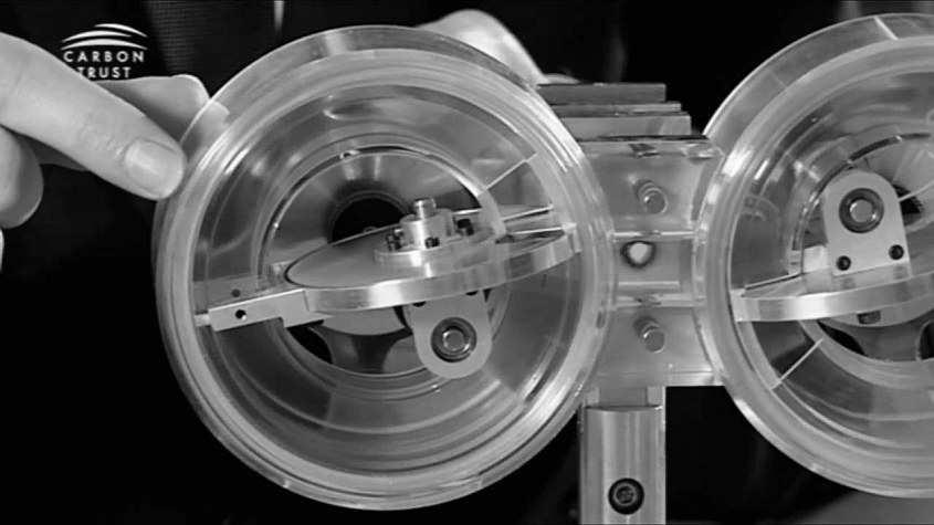
It is a rotary device with a wrapped toroidal chamber. The key features are a rotating blade, which passes through a slot in a rotating disc once per cycle. The unit is therefore a compact, double acting rotary compressor.
Animation of the design:
http://www.youtube.com/watch?v=b4J7LuoBpx8


The compressor has very substantial markets, and is suitable for various industrial air markets, blowers and specific process gas applications. Lontra’s initial focus is on waste water aeration, automotive superchargers and the industrial air market.
The
Blade Supercharger
The Blade Supercharger™ is an efficient, variable mass flow, positive displacement supercharger.
It uses the core design of the Blade Compressor™, optimised for engine package and performance requirements. The technology has unique abilities in matching the requirements for heavily downsized powertrains, both gasoline and diesel. The variable port design allows for real-time variation of mass-flow and internal compression ratio (without changing rotational speed), enabling precise matching of the boost requirements of the engine throughout the cycle.
The Lindsey Engine® is a patented, clean sheet design for an engine that could potentially deliver very significant improvements in efficiency and fuel economy. Our initial modelling indicates an improvement in efficiency at part load of up to 37% over traditional engines. The engine could be configured to run on petrol, or a range of alternative fuels including hydrogen and various biofuels. Small, lightweight, quiet, with fewer parts than a traditional engine and using well-understood materials and technology, the engine has very significant potential.
The engine has diverse potential applications, from electricity generation through marine power and potentially the automotive sector. Initial priority markets include 2-stroke replacement, Combined Heat and Power and Unmanned Aerial Vehicles.


The
Lindsey Engine
The Lindsey Engine® is a development from the Blade Compressor™, and shares the basic mechanical design. Two units are connected to create a traditional four stroke cycle, one performing induction/compression the other combustion/exhaust. The engine therefore offers the potential to optimise compression/combustion ratios and temperatures which, together with improved airflow, significantly improve energy efficiency over traditional engines.
A spin-out from the engine development programme is the Blade Expander™, a positive displacement expander with a high thermal efficiency which is capable of efficiently handling variable loads.
This makes it potentially valuable in a number of steam applications, and potentially for use in new biofuel applications.
Design of innovative Blade Compressor™ released
10 May 2010
Clean Tech developer Lontra has provided the first glimpse of the innovative Blade Compressor™, a technology that has been in development by the company since 2004.
The compressor, which was designed by Lontra’s Technical Director Steve Lindsey, is a rotary device with a wrapped toroidal chamber. The key features are a rotating blade, which passes through a slot in a rotating disc once per cycle. The unit is therefore a compact, double acting rotary compressor. An animation of the design, and an explanation of the technology, are at Lontra’s website www.lontra.co.uk
Prototypes demonstrate a 20% efficiency gain over traditional compressors, and has an innovative variable port design which allows it to meet changing application requirements whilst maintaining constant speed. The company has development projects underway with leading partners, including a development project for waste water compressors jointly funded by the Carbon Trust and Severn Trent Water.
The compressor is the core mechanical geometry of the range of Lontra’s applications, including the Blade Supercharger™, Blade Expander™ and Lindsey Engine®. technology.
http://www.greencarcongress.com/2011/06/lontra-20110620.html
20 June 2011
Lontra releases BladeBoost supercharger demonstrator results; next generation under development
The BladeBoost demonstrator was the third iteration of the compressor for a vehicle application. Click to enlarge.
UK-based clean technology developer Lontra has released performance results of the BladeBoost supercharger demonstrator—an efficient, variable mass flow, positive displacement supercharger for heavily downsized engines—following the conclusion of a development project supported by the UK’s Technology Strategy Board, in partnership with Ford Motor Company and Ricardo. (Earlier post.)
The BladeBoost uses the core design of the Blade Compressor, optimized for engine package and performance requirements. A key feature of the compressor is its ability to use a simple variable inlet port that allows dynamic control of mass flow rate and internal compression ratio without changing rotational speed. This enables the boost of downsized engines to be completely controlled at any point on the operating cycle, including part-load.
The compressor is designed for high volumetric and thermal efficiency, and the geometry of the compressor allows high efficiency heat recovery. It is oil free, and other features include small size, low vibration and quiet operation. The compressor is a rotary device with a wrapped toroidal chamber. Key features include are a rotating blade, which passes through a slot in a rotating disc once per cycle. The unit is therefore a compact, double-acting rotary compressor.
The BladeBoost vehicle demonstrator developed as part of the project with Ford and Ricardo represents the third iteration of the compressor for a vehicle application.
The chart to the right plots the measured performance of the BladeBoost against the latest Eaton R900 TVS supercharger, using the published map of thermal efficiency. At a drive ratio of 3:1 the R900 theoretically delivers similar flow rate to BladeBoost. Assumptions were that the engine mass flow rate is proportional to absolute manifold pressure; when throttled, Eaton supercharger efficiency is same as un-throttled (despite higher PR); theoretical power is calculated from PR and mass flow rate, without friction; and inlet air was assumed at a constant 20 °C.
The detailed data set shows how the Blade Supercharger is able uniquely to deliver the pressure and flow required for downsized engines, Lontra says.
In parallel to the physical hardware development, Lontra has been developing a detailed mathematical model of the compressor over the past four years. This is now a powerful tool that allows the company to test modifications to existing devices, or new devices for customers, before committing to costly hardware.
During the build of BladeBoost, the team identified four key, simple areas for improvement:
The chamber bleed hole was in the wrong position and so should be moved to the correct position.
The abradeable coating could be run-in more effectively in one key area (outer rotor).
The remaining clearances could be reduced to the design specification (some components were machined outside of specification).
The outlet port could be optimized.
The analysis model allows the developers to see what the effect of these improvements will be.
The next generation of Blade Supercharger (beyond BladeBoost) is under development. The new system will be smaller and more tightly packaged with a number of improvements including the capability to accept boosted inlet air for a post turbo-charger installation. This design of this device is complete including manufacturing drawings with some parts already manufactured, the company said.
Blade
process design and operation
According to Lontra, the design, common to the compressor, supercharger, expander and engine, is "novel positive displacement geometry". The basic unit uses a ring shaped chamber with a continually open inlet port and an outlet port valved by the action of the rotor.
The principal components are a blade ring, which rotates and rotating disc. The blade cuts through the disc.
The compression chamber is formed as the blade, rotating in the housing, works against the disc. The blade passes through the disc and is double acting, drawing gas in behind the compressing head. The compressed gas then exits through a port in the housing.
Product design allows for a variable flow device where the intake area, and pumped capacity and compression ratio, can be controlled through a sliding port.
The 1800 m3/hour Blade Compressor is a 35kW unit, producing 0.5 bar Gauge and a flow rate of 30Am3 per minute at 3000 rpm.
PATENTS
ROTARY PISTON AND CYLINDER DEVICES
WO2007093818
Also published as:
WO2007093818 // US2009120406 // JP2009526945 // EP1987231 //
CN102787867 ROTARY PISTON AND CYLINDER DEVICES
WO2007093818
A rotary piston and cylinder assembly (1) comprising two rotary piston and cylinder devices (2a, 2b) , each device comprising a rotor (7) and a stator (10) , the stator at least partially defining an annular cylinder space (3) , the rotor is in the form of a ring, and the rotor comprising at least one piston (8) which extends from the rotor ring into the annular cylinder space, in use the at least one piston is moved circumferentially through the annular cylinder space on rotation of the rotor relative to the stator, the rotor body being sealed relative to the stator, and the device further comprising cylinder space shutter means (5) which is capable of being moved relative to the stator to a closed position in which the shutter means partitions the annular cylinder space, and to an open position in which the shutter means permits passage of the at least one piston,; the cylinder space shutter means comprising a shutter disc, wherein the devices are connected by a transfer passage.
[0001] ROTARY PISTON AND CYLINDER DEVICES
[0002] This invention relates to rotary piston and cylinder devices which may be, for example, in the form of an internal combustion engine, or a pump such as a supercharger or fluid pump, or as an expander such as a steam engine or turbine replacement.
[0003] The term 'piston' is used herein in its widest sense to include, where the context admits, a partition capable of moving relative to a cylinder wall, and such partition need not generally be of substantial thickness in the direction of relative movement but can often be in the form of a blade. The partition may be of substantial thickness or may be hollow.
[0004] The invention relates in particular to a rotary piston and cylinder devices of the type comprising a rotor and a stator, the stator at least partially defining an annular cylinder space, the rotor is in the form of a ring, and the rotor comprising at least one piston which extends from the rotor ring into the annular cylinder space, in use the at least one piston is moved circumferentially through the annular cylinder space on rotation of the rotor relative to the stator, the rotor body being sealed relative to the stator, and the device further comprising cylinder space shutter means which is capable of being moved relative to the stator to a closed position in which the shutter means partitions the annular cylinder space, and to an open position in which the shutter means permits passage of the at least one piston, the cylinder space shutter means comprising a shutter disc.
[0005] In a highly preferred embodiment the at least one piston extends generally inwardly from the rotor ring and the stator is positioned generally internally of the ring. The stator may have portions which extend generally radially outwardly beyond the ring if desired.
[0006] Preferably the shutter disc presents a partition which extends substantially radially of the annular cylinder space.
[0007] Although in theory the shutter means could be reciprocable, it is much preferred to avoid the use of reciprocating components, particularly when high speeds are required, and the shutter means is preferably at least one rotary shutter disc provided with at least one aperture which in the open condition of the shutter means is arranged to be positioned substantially in register with the circumferentially-extending bore of the annular cylinder space to permit passage of the at least one piston through the shutter disc.
[0008] Preferably the at least one aperture is provided radially in the shutter disc.
[0009] Preferably the rotor is adapted to receive the shutter disc.
[0010] The shutter disc is preferably driven from the rotor through a suitable transmission means.
[0011] Preferably the axis of rotation of the rotor is not parallel to the axis of rotation of the shutter disc. Most preferably the axis of rotation of the rotor is substantially orthogonal to the axis of rotation of the shutter disc.
[0012] Preferably the piston is so shaped that it will pass through an aperture in the moving shutter means, without balking, as the aperture passes through the annular cylinder space. The piston is preferably shaped so that there is minimal clearance between the piston and the aperture in the shutter means, such that a seal is formed as the piston passes through the aperture. A seal is preferably provided on a leading or trailing surface or edge of the piston. In the case of a compressor a seal could be provided on a leading surface and in the case of an expander a seal could be provided on a trailing surface.
[0013] The rotor body is preferably rotatably supported by the stator rather than relying on co-operation between the pistons and the cylinder walls to relatively position the rotor body and stator.
[0014] It will be appreciated that this is distinct from a conventional reciprocating piston device in which the piston is maintained coaxial with the cylinder by suitable piston rings which give rise to relatively high friction forces.
[0015] The rotor ring is preferably rotatably supported by suitable bearing means carried by the stator.
[0016] Preferably the stator comprises at least one inlet port and at least one outlet port.
[0017] Preferably at least one of the ports is substantially adjacent to the shutter means.
[0018] Preferably the ratio of the angular velocity of the rotor to the angular velocity of the shutter disc is 1: 1.
[0019] Multiple connected devices (whether in the form of compressors, expanders or other form) may be joined to one or more common intake outlet manifolds. This may be to so that a more continuous flow of gas is input or outputted (as the multiple devices may have different intake phases etc.) . An example is a supercharger or compressor where two or more devices may be joined to a common output manifold to produce a nearly continuous output flow
[0020] According to one aspect of the invention there is provided a rotary piston and cylinder assembly comprising two rotary piston and cylinder devices, and a transfer conduit, the transfer conduit fluidically connecting an outlet port of one device to an inlet port of the other device.
[0021] According to one aspect of the invention there is provided a rotary piston and cylinder assembly comprising two rotary piston and cylinder devices of the type set forth, a transfer conduit which connects an output port of one device to an input port of the other device, and the assembly further comprising heat transfer means for bringing exhaust fluid of the other device into thermal communication with fluid in the transfer conduit.
[0022] According to another aspect of the invention there is provided a rotary piston cylinder assembly comprising two rotary piston and cylinder devices of the type set forth, a transfer conduit which connects an output port of one device to an input port of the other device, and the assembly further comprising means for conveying exhaust fluid of the other device into the transfer conduit.
[0023] According to a further aspect of the invention there is provided a rotary piston and cylinder assembly comprising two rotary piston and cylinder devices of the type set forth and a transfer conduit that connects an output port of one device with an input port of the other device, wherein the transfer passage is provided with turbulence generating means which, in use, causes turbulent flow of fluid passing through the transfer passage. According to another aspect of the invention there is provided a rotary piston and cylinder device comprising two rotary piston and cylinder devices of the type set forth and a transfer conduit which connects an output port of one device with an input port of the other device, the transfer conduit being provided with resonance control means which, in use, is operative to damp or amplify fluid pressure waves of fluid in the transfer conduit.
[0024] According to another aspect of the invention there is provided a rotary piston and cylinder device comprising two rotary piston and cylinder devices of the type set forth and a transfer conduit which connects an output part of one device with an input port of the other device, the transfer conduit being provided with compressed gas storage means, which in use, is operative to supply compressed gas into the transfer conduit.
[0025] According to a further aspect of the invention there is provided a rotary piston and cylinder device of the type set forth comprising an adjustable port arrangement, the adjustable port arrangement comprising a displaceable stator wall portion which is adapted to be movable relative to an aperture region provided in the stator which aperture region provides fluid communication between the cylinder space and a region external of the device, and the arrangement being such that the stator wall portion can be moved so as to alter the position and/or extent of the aperture relative to the annular cylinder space.
[0026] According to yet a further aspect of the invention there is provided a rotary piston and cylinder device of the type set forth in which the rotor is provided with an aperture region, and the stator is provided with an aperture region, at least one of the rotor and the stator being provided with a movable portion and when in communication, the aperture regions provide fluid communication between the annular cylinder space and a region external of the device, the arrangement of the device being such that, in .use, the movable portion can be moved and so the angular extent of at least one of the aperture regions can be altered.
[0027] Another aspect of the invention relates to a rotary piston and cylinder assembly comprising two rotary piston and cylinder devices of the type set forth and a transfer conduit which connects an output port of one device with an input port of the other device, the transfer conduit being provided with acoustically absorbent means.
[0028] According to another aspect of the invention there is provided a rotary piston and cylinder device of the type set forth comprising an adjustable port arrangement, the adjustable port arrangement comprising a displaceable portion which is adapted to be moveable relative to an aperture region provided in the rotor, which aperture region provides fluid communication between the cylinder space and a region external of the cylinder space, and the arrangement being such that the displaceable portion can be moved so as to alter the position and/or extent of the aperture region relative to the cylinder space.
[0029] Yet a further aspect of the invention concerns an internal combustion engine comprising two piston and cylinder devices of the type set forth, a transfer conduit which connects an output port of one device to an input port of the other device and fuel injection means, the fuel injection means being arranged to issue fuel into the transfer conduit.
[0030] Various embodiments of the invention will now be described, by way of example only, with reference to the accompanying drawings in which: Figure 1 is a side elevation of a first rotary piston and cylinder assembly;
[0031] Figures 2a, 2b, 2c and 2d are perspective views of each principal component of each rotary piston and cylinder device of the assembly of Figure 1;
[0032] Figure 3 is a side elevation of a second rotary piston and cylinder assembly;
[0033] Figure 4 is a side elevation of a third rotary piston and cylinder assembly;
[0034] Figure 5 is a side elevation of a fourth rotary piston and cylinder assembly;
[0035] Figure 6 is a side elevation of a fifth rotary and piston cylinder assembly;
[0036] Figure 7 is a side elevation of a sixth rotary piston and cylinder assembly;
[0037] Figure 8 is a perspective view of a first variable port arrangement;
[0038] Figure 8a is a perspective view of part of the first variable port arrangement shown in Figure 8 in which a slidably mounted port cover has been removed;
[0039] Figure 9 is a perspective view of a second variable port arrangement; Figure 10 is another perspective view of a third variable port arrangement;
[0040] Figure 11 is another perspective view of the variable port arrangement shown in Figure 10;
[0041] Figure 12 is a perspective view of a fourth variable port arrangement;
[0042] Figure 12a is a perspective view of part of the fourth variable port arrangement in which a pivotally mounted port cover has been removed;
[0043] Figure 13 is a perspective view of a fifth variable port arrangement;
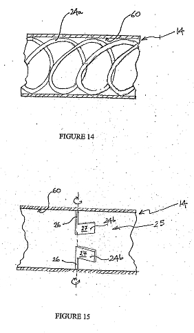
[0044] Figure 14 shows a schematic representation of an embodiment turbulence generating means;
[0045] Figure 15 shows a schematic representation of a further embodiment of a turbulence generating means;
[0046] Figure 16 is a schematic view of an outer housing of a rotary piston and cylinder device in a first condition;
[0047] Figure 17 is a schematic view of the outer housing of Figure 16 in a second condition;
[0048] Figure 18 is a schematic view of outer housing of a rotary piston and cylinder device in a first condition; Figure 19 is a schematic view of outer housing of a rotary piston and cylinder device in a second condition;
[0049] Figure 20 is a side elevation of a combustion engine with ignition means in a first location;
[0050] Figure 21 is a side elevation of a combustion engine with ignition means in a second location, and
[0051] Figure 22 is a side elevation of a combustion engine with ignition means in a third location.


[0052] Figure 1 shows a rotary piston and cylinder assembly 1 forming a combustion engine. The assembly 1 comprises two piston and cylinder devices 2a and 2b which are connected by a transfer passage 14. The engine may be considered as two conjoined positive displacement pumps, with one chamber providing induction and compression and the other combustion and exhaust. This separation of cycles allows for their optimisation without compromise, and significant benefits are achieved. The transfer passage 14 may be of construction or material such as ceramic to thermally insulate the devices 2a and 2b from one another to some extent. Since one of the options is to run the two devices at different temperatures. The engine combines the advantages of both a turbine and a reciprocating engine. It allows efficient operation over a wide range of speeds and conditions while at the same time all motions are purely rotary and the intake and exhaust are continually open as in a turbine engine.
[0053] Figures 2a, 2b, 2c and 2d show the principal components of each of the piston and cylinder devices 2a and 2b. Figure 2a shows a stator 10 which is provided with a port 11 in the side wall 12 and the two side walls 12 and base 13 defining an annular cylinder space 3. The stator 10 has a radial slot 4 which is dimensioned to receive a shutter disc 5 whose purpose is to partition the annular cylinder space 3.
[0054] Figure 2b shows the shutter disc 5 which fits into the slot 4 in the stator 10 and partitions the annular cylinder space 3. The shutter disc 5 is provided with a slot 6 to allow a suitably shaped piston 8 to pass therethrough.
[0055] Figure 2c shows a rotor ring 7 and extending inwardly thereof is attached the piston 8. The ring 7 fits around the outside of the stator 10 to enclose the annular cylinder space 3. The ring 7 and the piston 8 rotate around the stator 10 on suitable bearings (not shown) provided on the stator 10. The ring 7 is provided with a grilled port 9 which is adjacent to the piston 8.
[0056] The width of each of the openings forming the grilled port 9 in the direction of the rotor is less than the thickness of the shutter disc 5. The shutter disc may incorporate an extension on its edge to increase its thickness.
[0057] Figure 2d shows a static outer housing 30 which fits around the outside of the rotor ring 7 and is provided with a port 31. The combined action of the port 9 in the rotor ring 7 and the port 31 in the static outer housing forms a valve, which, is in an open condition when the two parts are aligned (or at least in fluid communication) and closed when they are not. Rotation transmission means (not shown) rotationally connects axle 4 of the shutter disc 5 to the rotor ring 7 to ensure a suitable relative speed so that the piston 8 can pass through the slot 6 without balking.
[0058] Returning to Figure 1 the transfer passage 14 connects the outlet port 31a of the compressor device 2a and to the inlet port 31b of the expander device 2b.
[0059] The port 11a in the side wall of the stator 10a on the device 2b forms the intake port through which fresh charge is drawn.
[0060] The port lib in the side wall of the stator 10b of the expander device 2b forms an exhaust port through which spent charge is exhausted.
[0061] Forming an engine by conjoining a compressor device and an expander device in this way allows the compression cycle and the expansion cycle to be optimised independently. For example the compressor device 2a can be run at a different temperature to the expander, the compressor device 2a may use different sealing or different lubrication strategies to the expander, and/or the compression ratio of the device 2a and the expansion ratio of the device 2b can be different.
[0062] The engine assembly 1 can be configured so that the transfer occurs at constant volume or alternatively the gas can continue to be compressed during transfer (possibly a small amount to make up for any leakage) or even expanded.
[0063] Exhaust gas from the expander device 2b can be transferred from the exhaust port lib through a manifold 19 to a heat exchanger 20. The heat exchanger 20 extends through the transfer passage 14. More particularly the heat exchanger 20 comprises a plurality of relatively narrow conduits 40 which are spaced by gaps 41. The gaps 41 allow the fluid in the transfer passage to pass therethrough and accordingly enhance the heat transfer to said fluid.
[0064] The heat exchanger 20 exchanges heat between the exhaust gas from the expander device 2b and the gas in the transfer passage 14 which is yet to enter the expander device 2b.
[0065] Importantly the heat exchanger 20 does not allow the exhaust gas therein to mix with the gas in the transfer passage 14.
[0066] The transfer of heat from the hot exhaust gas to the transfer passage gas allows some of the energy to be recovered, and so increases the overall efficiency of the engine assembly 1. In addition such heat recycling could be used to 'tune' the engine temperature and so reduce the warm-up time of the expander device 2b.
[0067] This heat recycling does not affect the volumetric efficiency of the compressor device 2a because the intake air to the compressor device 2a remains unheated.
[0068] In use of the engine assembly 1 the compressor device 2a, draws fluid through the open port 11a as the piston 8a and rotor ring 7 rotate. At the same time as inducing air behind the piston 8a, fluid induced in the last complete rotation of the rotor ring 7 is compressed in front of the piston 8a against the shutter disc 5a.
[0069] As the port 9a in the rotor ring 7a and the port 31a in the static outer housing 30a come into register, the valve so formed opens and the compressed fluid is discharged into the transfer passage 14. In the expander device 2b, pressurised fluid enters the cylinder space of the device through the port 31b in the outer housing 30b and the port 9b in the rotor ring 7b. As the rotor ring 7b rotates, the valve closes and the pressurised fluid is expanded. Ignition means (not shown) , such as a spark plug provided in the stator 10b, then ignites the fuel mixture.
[0070] After further rotation the port lib allows the remaining gas to escape into the manifold 19. Further remaining fluid is forced through the port lib during the next expansion cycle.
[0071] It will be appreciated that a rotational output of the ring 7b drives both the shutter disc 5b and, by way of suitable rotational transmission means (not shown) the rotor ring 7a and the shutter disc 5a of the compressor device 2a.
[0072] In an alternative embodiment a heat exchanger is not provided and exhaust gas from the expander device is merely channelled away from the transfer passage towards an exhaust manifold (not shown) .
[0073] Figure 3 shows device 2a of an internal combustion engine 100, in which like reference numerals indicate like features and wherein a proportion of exhaust gas is re-circulated to the transfer passage 14. A route for exhaust gas to pass from exhaust manifold 21 back to the transfer passage 14 is provided by an additional manifold 23. A pump 22 is operative to control the flow of exhaust gas between the exhaust manifold 21 and the transfer passage 14. It will be appreciated that further valves, pumps or other fluid control means may be employed to control this flow. This exhaust gas recirculation may be used to control combustion or burn rate. It may also be used to control the temperature in the expander device 2b. Further it may be used to control emissions or to help control a controlled auto-ignition (CAI) cycle. These are just some of the reasons that exhaust gas recirculation into the transfer passage 14 may be used. Recirculation in this way does not affect the volumetric efficiency of the compressor device 2a.
[0074] Attention is now given to the location of ignition means in an expander device of an engine. With reference to Figure 20 there is shown a combustion engine 1000 comprising two conjoined rotary piston and cylinder devices 2a and 2b. The expander device 2b is provided with a spark plug 950. Specifically the electrodes of the spark plug 950 are located in a recess or nacelle 952 of the base 13 of the stator.
[0075] Figure 21 shows a combustion engine 1100 in which the spark plug 950 is located in a recess of the outer housing 30 of the expander device 2b.
[0076] Accordingly the working fluid in the chamber is only exposed to the electrodes of the spark plug when the intake port 9b is in register with the spark plug. Advantageously since the spark plug is only exposed to the hot combustion mixture for a short time the lifetime of the spark plug should be improved. In one embodiment a glow plug may be provided in place of a spark plug and the ignition timing being provided by the interaction of the glow plug with the intake port 9b.
[0077] Figure 22 shows a combustion engine 1200 in which a spark plug 950 is provided in a recess of a side wall 12 of the stator.
[0078] Figure 4 shows an internal combustion engine 200 which includes an arrangement 24 which is adapted, in use, to modify the flow of gas within the transfer passage 14 so as to encourage turbulent fluid flow in the passage. The arrangement 24 may be realised in numerous ways and may be static, movable and/or powered. The arrangement (shown schematically at 24) may comprise a flap or flaps extendible into the transfer passage space or a number of other features or shapes having surface portions on which the gas impacts in order to modify the fluid flow characteristics thereof. The arrangement 24 may be described as an aerodynamic device. The turbulence created in the transfer passage may comprise one or a combination of a swirling motion and/or a tumbling motion.
[0079] The arrangement 24 may be deformable such that its configuration presented to the fluid changes as the rate of fluid flow through the passage 14 and on to the device changes. The arrangement 24 may be dynamically controllable (in real time) by way of user controllable motive means or settable at the time of manufacture (to account for different fuels etc) . Accordingly the position, shape, configuration and/or orientation may be set or dynamically controlled.
[0080] The amount of turbulence generated may be modified to control the mixing of fluids in the transfer passage 14 so as to control the mixing of fuel and air in the transfer passage 14 or to affect conditions later in the cycle, in the expander device 2b (which is downstream of the arrangement 24) .
[0081] Alternatively the turbulence generated could be used to control the mixing of the transfer passage fluid and any recirculated exhaust fluid, either within the transfer passage or downstream of the arrangement 24 in the expander device 2b. The control of turbulence could be used to allow the heat transfer rate between a heat exchanger (such as heat exchanger 20) and the gas in the transfer passage 14 to be controlled.
[0082] Importantly, the degree of turbulence of fluid in the transfer passage 14 controls at least in part the combustion in the expander device 2b and so appropriate control of the turbulence could be used to maximise the efficiency of combustion. The optimum amount of turbulence varies for different engine operating speeds, different engine loads and different fuels.
[0083] A particular benefit of the location of the arrangement 24 in the transfer passage 14 is that the turbulence is generated just before the charge is combusted allowing for minimal energy loss (to effects such as viscous flow) from the fluid. This is in contrast to a traditional reciprocating engine in which turbulence is generated by the flow of gas through the intake valves and then must go through a compression cycle before combustion (giving more time for a loss of turbulence energy) .
[0084] A turbulence generating arrangement 24a is shown in Figure 14, and comprises a vane of substantially helical form which extends radially inwardly from inner wall 60 of the transfer passage 14.
[0085] A further turbulence generating arrangement 24b is shown in Figure 15 which comprises two rotatably mounted flap devices 25. Each flap device 25 comprises a stem 26 which is torsionally flexible (as indicated by the double-headed arrows) and the stem is connected to a flap portion 27. The arrangement is such that in use at low fluid flow rates each flap device would present a large surface to the fluid and so increased turbulence is generated. However, if the fluid rate increased then the stems 26 would be caused to flex and so the surface area presented to the fluid flow would decrease. In yet a further alternative 'passive<1> arrangement a stem of a rotatably mounted flap device is engageable with resilient biasing means (for example a spring) wherein the flap device is biased towards presenting a higher surface area to the fluid flow. In an alternative embodiment the stems 26 are of substantially rigid construction and each flap portion is of a sufficiently flexible construction to provide flexure in response to variations in the fluid flow rate.
[0086] In an alternative arrangement each of the flap devices is connected to motive means (not shown) which means is operative to control the inclination of each device relative to the direction of fluid flow in the transfer passage. In the above described flap device embodiments, although two flap devices are described, one or more such devices may be implemented.
[0087] Figure 5 shows an internal combustion engine 300 in which a fuel injector 25 injects fuel 26 directly into the transfer passage 14. Alternatively or in addition, however, the fuel may be injected into the compressor intake port 4a, into the compressor intake manifold, into the annular cylinder space itself or into the expander chamber.
[0088] Injection into the transfer passage 14 has the benefit not reducing the volumetric efficiency of the compressor device 2a.
[0089] Injecting into the transfer passage 14 also means that there is no fuel in the compressor 2a to wet the walls thereof, which would affect lubricants or damage coatings. Advantageously the absence of fuel in the compressor device 2a allows optimisation of the materials of construction thereof.
[0090] Further injection of fuel into the transfer passage 14 may allow further control of charge stratification (by injecting more fuel into some of the charge passing through the transfer passage than other) . This has the benefit in controlling combustion.
[0091] Multiple injectors may be used, as may multiple transfer passage manifolds.
[0092] Figure 6 shows an internal combustion engine 400 comprising a receptacle/storage tank 27 which is attached to the transfer passage 14 by valve means 28 which allows compressed fluid to be stored between cycles .
[0093] In use, during a braking cycle of the engine, the valve 28 would allow the compressed gas to be stored in the receptacle 27. Then, when re- accelerating, a variable intake port (not shown) or other suitable means could reduce the pressure attained in the compressor device 2a reducing the compression work required. Gas would be allowed to re-enter the transfer passage 14 from the receptacle 27 to make up the pressure difference (as if the variable port had not been used to reduce the compression ratio) . Overall this would advantageously allow an increase in efficiency as the energy from engine braking would be re-captured and this forms a type of 'weak' hybrid. This is just one example of the use of the receptacle 27 and the valve means 28. In addition or alternatively, compressed gas captured during the engine braking cycle could be used for one or more devices, either attached to the engine 400 or otherwise, for example a pneumatic braking system. The valve means 28 may be operatively connected to control means such that compressed gas received from the device 2a (when the valve means 28 is opened) could be released from the tank 27 towards the device 2b in subsequent cycles of the device 2a so performing gas storage and gas release steps.
[0094] In an alternative embodiment a chamber 29 may be in the form of an expansion chamber, wherein at a specific frequency a sudden change in cross-sectional area of the chamber 29 is brought about so as to reflect waves towards the transfer passage.
[0095] It is possible that the engine 400 could be powered purely on compressed gas from the receptacle 27 in some instances with power derived from expanding the compressed air in the expander device 2b. This would require either bypassing the compressor stage or using variable porting (as hereinafter described) to reduce the compression ratio.
[0096] In yet another alternative embodiment the receptacle 27 is in the form of a source of compressed gas which gas is not provided from the compressor device 2a. In such an embodiment the valve 28 is a one-way valve allowing only gas to enter into the passage 14 and not vice versa.
[0097] Figure 7 shows an internal combustion engine 500 comprising chambers 29 of substantially cylindrical shape which are attached to the transfer passage 14. These chambers allow the regulation of the resonance of the transfer passage and/or other parts of the engine caused by the interaction of pressure waves in the fluid which occurs as a result of the valves 31a and 31b being periodically opened and closed. Element 50 is a baffle/plate member which is operative to modify the effect of the resonant chamber. Two chambers 29 are shown, however there may be one or multiple resonant chambers. Entry of fluid into one or more of the resonant chambers may be controlled by valves (not shown) which are selectively operable to isolate the chamber(s) from the transfer passage. In use, one or more resonant chambers act to damp the resonant effects of fluid in the transfer passage and so improve fluid flow and reduce noise. Various embodiments of chambers 29 may be envisaged. In one embodiment a chamber is in the form of a Helmholtz resonator-type arrangement, wherein at a specific frequency of pressure wave in the fluid the chamber resonates and waves are emitted towards and into fluid in the transfer passage so as to alternate resonance of pressure waves in the transfer passage. A further possibility is that a mechanism may be employed to allow the volume or length of the chamber (s) to be varied. One realisation of such an arrangement comprises a telescopic chamber. An alternative embodiment comprises a piston which is controllably moveable within a chamber. Further embodiments could be envisaged where multiple sub-chambers are fluidically connected by valves to allow the resonant volumes of the chambers to be modified. Such sub- chambers may be connected to the transfer passage so provide a return route thereto. In an embodiment the resonant chambers are adapted to amplify the resonant effect on the transfer passage such that, in use, constructive interference of pressure waves in the transfer passage is brought about.
[0098] In an alternative embodiment an acoustically absorbent material is provided in acoustic communication with the transfer passage such that, in use, pressure waves are dissipated as they pass through the transfer passage. In one realisation of such an embodiment the transfer passage is surrounded by acoustically absorbent material. Although only one transfer passage is shown between the devices 2a and 2b, multiple transfer passages may be provided.
[0099] It will be appreciated that other embodiments of the invention comprise two rotary piston and cylinder devices 2a and 2b, a transfer passage therebetween and at least two of the heat exchanger arrangements of Figure 1 , the exhaust gas recirculation arrangement of Figure 3, the turbulence generating arrangement of Figure 4, the fuel injection arrangement of Figure 5, the compressed fluid receptacle of Figure 6 and the resonant chamber of Figure 7.
[0100] Although in the above described embodiments the inlet and outlet ports of the devices 2, 2a and 2b are shown as being of fixed size, various further embodiments will now be described relating to control of port size using variable port arrangements.
[0101] With reference to Figure 8 there is shown a stator assembly 600 of a rotary piston and cylinder device comprising a variable port arrangement.
[0102] The arrangement comprises a slidable cover member 602 of substantially curved planar form which is adapted to slide in the arcuate aperture 601a provided in side wall 603. The surface of the cover member 602 that faces into the cylinder space is arranged to be substantially flush with adjacent inwardly facing surface portions of the side wall. Accordingly the cover member 602 is intended to 'replace' a side wall portion, at least from the piston's perspective such that no leakage path is created as the piston passes over the cover member. The side wall 603 in Figure 8 may be substantially planar. This plane may be substantially radial to the disc axis or may be offset from a radius of the disc axis. When discussing the angular extent of the ports, it is the axis about which the rotor ring 7 rotates and the axis around which the annular cylinder space 3 is formed which is referred to as a basis for determining angular coverage.
[0103] The slidable cover member 602 is adapted to be slid through an arc so as to selectively control the angular extent of the aperture 601a.
[0104] The stator assembly 600 is further provided with a second aperture 601b, the angular extent of which is not capable of being altered by movement of the slidable cover member 602.
[0105] The adjustability of the slidable cover member 602 relative to the aperture 601a allows the compression ratio to be altered. The point at which the compression stage starts is controlled in part by the angular position at which the piston 8 on the rotor ring 7 passes the end of the angular extent of the apertures 601a and 601b. If the angular extent of the aperture 601a port is increased, then the compression will start later in the rotation of the rotor ring. If all other parameters are the same this will lead to a reduction in the compression ratio. The volume of gas delivered from the outlet port of the device will remain the same if the timing of the interaction of the port provided in the rotor ring and the aperture provided in the outer housing from the outlet valve, remain the same.
[0106] With regard to Figure 8 it will be appreciated that although the slidable cover member 602 is shown as being rotatable towards the centre of the device, in an alternative embodiment the cover member may be arranged to be rotatable outwardly of the device. Control of the compression ratio in this way could be used in a compressor to control the outlet pressure in response to system demands.
[0107] Control of the port in this way in a supercharger embodiment would allow the mass flow of the supercharger to be varied without a variation in the supercharger rotational speed.
[0108] Control of the compression ratio in this way could be used to allow a form of engine throttling, reducing the power generated by the engine without the losses associated with a conventional throttle. A conventional throttle acts as a restriction in the intake of an engine, reducing the pressure downstream of it. The engine induces the same volume of air but at lower pressure, so that there is a net reduction in the number of air molecules and hence a reduction in the amount of fuel that can be burnt leading to a reduction in power. However, by using a controllable intake port (as formed by the slidable cover member 602 in combination with the aperture 601a) instead, increasing the angular extent of the aperture 601a effectively reduces the amount of air that is compressed, without a large reduction in the intake pressure. The overall effect is that fewer air molecules are delivered to the combustion chamber as with the conventional throttle, but importantly the pumping losses of the throttle restriction are avoided.
[0109] Similarly, modifying the exhaust port of the stator of an expander device (eg device 2b) allows the expansion ratio to be altered. The angular position at which the expansion within the chamber ends is controlled by the point at which the piston on the rotor ring passes the start of the exhaust port. If the angular extent of the exhaust port is increased, then the expansion will end earlier in the rotation of the rotor ring. If all other parameters are the same this will lead to a reduction in the expansion ratio . The volume of gas delivered through the inlet port of the device will remain the same if the timing of the interaction of the port provided in the rotor ring and the aperture provided in the outer housing that form the outlet valve and all other parameters, remain the same.
[0110] Reducing the expansion ratio in an engine could reduce the amount of work produced by the engine and increase the temperature of the exhaust. Where the engine is used as part of a Combined Heat and Power (CHP) apparatus, this would allow the heat to power ratio of the system to be controlled.
[0111] Temporarily increasing the exhaust energy by reducing an engine embodiment's expansion ratio could be used to heat up a downstream catalyst more quickly. This could reduce 'light-off emissions.
[0112] Temporarily increasing the exhaust energy by reducing the engine embodiment's expansion ratio could be used to provide more energy for a downstream turbocharger to 'spool up' , reducing 'lag' or the time that it takes to respond to a change in engine operating conditions.
[0113] Control of the expansion ratio in this way could be used in a single rotary piston and cylinder device forming an expander (such as a steam expander) to control the amount of work produced by the expander. It could also be used to control the outlet pressure of an expander.
[0114] These are only a few of the many possible advantages that could be gained from expansion ratio control.
[0115] With reference now to Figure 9 there is shown a variable port arrangement provided in the outer housing of the stator of a rotary piston and cylinder device in which the port 711 is variably valved by a slidable member 712. The wall has formed therein a channel of substantially part helical form defined by wall portions 713. The slidable member 712 is intended to "replace" a portion of the outer housing, at least from the piston's perspective such that no leakage path is created as the piston passes over the slidable member. The aperture in the outer housing 711 and the port 9 in the rotor ring 7 forms a valve which is open when the port 9 and aperture 711 are substantially in register. The slidable member 712 allows the timing of this valve to be varied. The slidable member allows the angular extent of the aperture 711 to be controlled, in the same way as the variable aperture 601a in Figure 8.
[0116] In an alternative embodiment a port is provided in the outer housing, and a curved slidable member is designed to move substantially circumferentially (ie substantially co-axially of the axis of the outer housing) around the cylinder space within the port (rather than helically or in part axially) .
[0117] In a variant embodiment the port 711 is provided in the radially innermost base wall 13 of the stator of the rotary piston and cylinder device.
[0118] In a variant embodiment a port controlled by a slidable member is provided in the rotor ring 7 in addition to or replacing a port 9. This allows the timing of the valve formed by the interaction of the first mentioned port and an aperture in the outer housing to be adjusted.
[0119] In a compressor device the interaction of the port in the rotor ring and the port 711 can be used to control the compression ratio.
[0120] If the compression ratio is reduced in the compressor by increasing the inlet port angular extent (described above) , the volume compressed is reduced and the volume delivered from the outlet port remains the same (if no other parameters are changed) . If instead the compression ratio can be reduced by sliding the member 712 so as to increase the angular extent of the port 711 which may replace either the port 9 in the rotor ring 7 or the aperture 31 in the outer housing 30, the volume compressed remains the same, but the volume delivered from the outlet port is increased.
[0121] In one embodiment both the angular extent of the port 9 in the rotor ring 7 and the angular extent of the aperture 31 in the outer housing 30 may be variable.
[0122] If both the inlet port angular extent and the outlet valve timing (which timing is controlled by the angular extents of the port 9 and the aperture 31) can be varied, the compressed volume or mass flow and the compression ratio can be independently varied. For example if the angular extent of the inlet port is increased, the volume compressed is reduced. If the outlet valve timing remained the same, the compression ratio would be reduced, but if the extent of one or both of the ports forming the outlet valve is reduced, the compression ratio can be maintained. This means that the mass flow has decreased without a change in the compression ratio.
[0123] In an expander device, the inlet port is formed by the interaction of the port in the rotor ring and the port 711 and by sliding movement of the member 712 the angular extent of the port 711 can be used to control the expansion ratio. For example, the expansion ratio can be reduced by increasing the angular extent of the port 711, the volume expanded increases, but the volume delivered from the outlet port remains the same. With reference to Figure 16 there is shown an outer housing 830 of a rotary piston and cylinder device. The outer housing comprises two housing components 831 and 832, which are provided with apertures 841 and 842 respectively. The apertures 841 and 842 combine to serve as an input port for an expander device and an output port for a compressor device. The housing component 832 is mounted for rotational movement relative to the housing component 831. As shown in Figure 17 the housing component 832 has been rotated relative to the housing component. In so doing the position of the aperture 842 has now changed relative to the aperture 841. Accordingly the timing of when an aperture of the rotor of the device comes into (at least partial) register with the other aperture (and in particular the aperture 842) is altered. It will be appreciated that more than two rotatable outer housing components could be provided, with each component being provided with one or more respective apertures.
[0124] Figure 18 shows an outer housing 930 of a rotary piston and cylinder device. The outer housing 930 comprises multiple aperture regions 940 which together form an output port. The outer housing 930 is mounted for rotation relative to the cylinder space.
[0125] Figure 19 shows the outer housing 930 in an adjusted position in which the timing of the aperture of the rotor comes into register with the aperture regions 940 is altered (as compared to that for the position shown in Figure 18) .
[0126] In Figure 10, a stator 630 comprising an alternative variable port arrangement is shown. The arrangement comprises two removable plug elements 631 and 632 which can be secured to or moved from the stator and so vary the angular extent of the port 634. The elements can be selectively moved to form a continuous port or alternatively can be arranged to be separated such that multiple ports may be opened.
[0127] As best seen in Figure 11 the port 634 is provided by a grill or grating structure in a side wall of the stator which is adapted to receive projections 635 of each plug element 631 and 632. In an alternative embodiment the port 634 may not have a grill structure, for example as single opening.
[0128] In an alternative embodiment the plug elements could be hinged at one end (either the radially innermost end or the radially outermost end) to the stator so as to be capable of pivoting towards and away from the port 634 so as to allow them to be opened or closed and thus selectively alter the angular extent of the port.
[0129] In a further embodiment multiple port cover elements are hingedly attached to a side wall of the stator whereby hinges are provided at one of the sides (as opposed to the ends) of each port cover element. In yet a further embodiment multiple angularly spaced port cover elements are slidably mounted in a side wall of the stator, such that in use, each element can be slid either substantially radially inwardly towards the rotational axis of the rotor or substantially radially outwardly from the rotational axis.
[0130] Figure 12 shows a further variable port arrangement of a stator 640 which comprises a pivotable cover 641 hinged at 642 so as to be able to selectively control the angular extent of port 643 that is provided in the stator side wall. A further port 644 of fixed angular extent is also provided in the stator side wall. The port 643 is best seen in Figure 12a in which the pivotable cover 641 has been omitted. The wall in which the port 643 is formed may be a substantially planar wall.
[0131] Figure 13 shows a variable port arrangement provided in the outer housing 24 in which one edge is formed by multiple slidable valve members 725, 726, 727 and 728 which can slide relative to the port 724. In an alternative embodiment the variable port arrangement shown in Figure 13 may be used to vary the angular extent of a port 9 in a rotor ring 7.
[0132] In an alternative embodiment the variable port arrangement shown in Figure 13 may be provided in a radially innermost base wall 13.
[0133] In an alternative embodiment one or more of the valve members 725, 726, 727 and 728 are capable of moving towards and away from the port 724 in a direction generally radial of the annular cylinder space.<">
[0134] In a further alternative embodiment one or more of the valve elements 725, 726, 727 and 728 could be hinged at one end or side, or mounted on another pivot to allow the elements to be opened or closed. In yet a further alternative embodiment one or more of the valve elements 725, 726, 727 and 728 could reciprocate substantially radially with respect to the chamber axis or in another direction to vary the extent of the port.
[0135] In a further alternative embodiment the multiple elements 725, 726, 727 and 728 could be joined pivotally to one another so that they can 'unwrap<1> from the port in the form of a 'chain' . Specifically, adjacent edges 729 of each element are connected by way of a hinge arrangement (not shown). In use, if it is required to increase the size of the opening, then the appropriate number of elements are folded against each other in concertina fashion into a ' stack' whilst the other element/ s remain in position to cover part of the port opening. Conversely if it is required to decrease the size of the port opening then the required number of elements is/are 'unwrapped' from the stack to close the opening. Other embodiments are possible in which the elements can be lifted away from the opening rather that folding into a stack.
[0136] In an alternative embodiment to those shown in Figures 9 and 13, the angular extent of port provided in the rotor ring (eg port 9a) could be adapted to be capable of being varied so as to alter the angular extent of the aperture. This could be achieved by providing one or more plug members (not shown) which are adapted to be capable of being removeably inserted into one or more of the openings which form the grill structure of the port of the rotor ring 7.
[0137] If both inlet ports and outlet ports of a rotary piston and cylinder device were provided with a variable port arrangement, then the compression ratio (for example) , the volume compressed and the volume delivered could be independently controlled by control of one or both of the inlet and outlet ports.
[0138] In the case of a rotary piston and cylinder device used as a compressor, the volume compressed could be reduced by increasing the angular extent of the inlet port of the stator. If the angular extent of the outlet port of the outer housing (forming the outlet valve) remained the same the compression ratio would be reduced. If, however, the angular extent of one or both of the outlet ports which together form the outlet valve were reduced, then the compression ratio could be maintained. This would result in a reduction of the volume compressed without a change in the compression ratio or delivery power. This effectively allows the compressor capacity or mass flow to be changed.
[0139] In the case of an engine embodiment such a valving strategy could be used to provide an advanced throttling capability. Maintaining the compression ratio while reducing the volume compressed would increase the engine efficiency over simply reducing the compression ratio and volume compressed.
[0140] In the case of an engine embodiment a variable inlet port in the outer housing of the expander device could be used in conjunction with a variable outlet port from the compressor device. The variable outlet port from the compressor device would allow the compression ratio to be controlled (independent of the volume compressed) , the variable inlet port to the expander device would allow the port timings to be matched as the compressor outlet port was changed.
[0141] It will be appreciated that a plurality of one or more different types of any of the variable port arrangements described above could be distributed around the annular cylinder space, for example multiple angularly spaced inlet ports may be provided. Any of the variable port arrangements above may be provided on their own or in conjunction with one or more ports of fixed size. Any of the variable port arrangements described above may be used in combination for the same rotary piston and cylinder device or for an assembly comprising two conjoined devices.
[0142] The variable port arrangements described above may be controlled in a variety of ways. For example a variable port arrangement could be controlled by way of manual intervention, either at the time of manufacture and/or as part of a subsequent adjustment or tuning procedure. A variable port arrangement could be controlled by way of suitable actuation means, such as a servo-device, in which a control signal sent to the actuation means adjusts the angular extent of the port. Such actuation means could be arranged to be controlled in real-time during operation of the respective rotary piston and cylinder device in response to control signal from one or more sensors and/or in response to data stored in memory means. The actuation means could be controlled by an engine management system which comprises a data processor and memory means, for example in the form of a firmwave device. Accordingly, operation of the rotary piston and cylinder device could be optimised by way of control of the variable port arrangement in response to varying demands on the device. For example in an engine embodiment such a change could occur as a result of cruising at steady power/speed to accelerating. In a compressor such a change may be constituted by a change in the flow of fluid demanded or the required delivery pressure required. In a supercharger (that may be attached to a conventional engine, for example) , such a change in porting may occur to increase the mass flow in response to increased engine power demand.
ROTARY
PISTON AND CYLINDER DEVICES
WO2010023487
WO2010023487
Also published as: WO2010023487 // US2011174095 // EP2334908 // EA201170378
A transmission assembly for a rotary piston and cylinder device, comprising a first gear (120) and a gear sub-assembly (15, 16, 17, 18, 19), the first gear connectable to a rotatably mounted shutter (12) of the device, and the first gear extending from a side of the shutter, and the first gear connected to the gear sub-assembly which converts rotation to an axis of rotation different to that of the shutter.
Field
The present invention relates generally to rotary piston and cylinder devices.
Background
Rotary piston and cylinder devices can take the form of an internal combustion engine, or a pump such as a supercharger or fluid pump, or as an expander such as a steam engine or turbine replacement.
A rotary piston and cylinder device comprises a rotor and a stator, the stator at least partially defining an annular cylinder space, the rotor is in the form of a ring, and the rotor comprising at least one piston which extends from the rotor ring into the annular cylinder space, in use the at least one piston is moved circumferentially through the annular cylinder space on rotation of the rotor relative to the stator, the rotor body being sealed relative to the stator, and the device further comprising cylinder space shutter means which is capable of being moved relative to the stator to a closed position in which the shutter means partitions the annular cylinder space, and to an open position in which the shutter means permits passage of the at least one piston, the cylinder space shutter means comprising a shutter disc.
The term 'piston' is used herein in its widest sense to include, where the context admits, a partition capable of moving relative to a cylinder wall, and such partition need not generally be of substantial thickness in the direction of relative movement but can often be in the form of a blade. The partition may be of substantial thickness or may be hollow. The shutter disc may present a partition which extends substantially radially of the annular cylinder space.
Although in theory the shutter means could be reciprocable, it is preferred to avoid the use of reciprocating components, particularly when high speeds are required, and the shutter means is preferably at least one rotary shutter disc provided with at least one aperture which in the open condition of the shutter means is arranged to be positioned substantially in register with the circumferentially-extending bore of the annular cylinder space to permit passage of the at least one piston through the shutter disc.
The at least one aperture of the shutter is provided substantially radially in the shutter disc.
Preferably the axis of rotation of the rotor is not parallel to the axis of rotation of the shutter disc. Most preferably the axis of rotation of the rotor is substantially orthogonal to the axis of rotation of the shutter disc.
Preferably the piston is so shaped that it will pass through an aperture in the moving shutter means, without balking, as the aperture passes through the annular cylinder space. The piston is preferably shaped so that there is minimal clearance between the piston and the aperture in the shutter means, such that a seal is formed as the piston passes through the aperture. A seal is preferably provided on a leading or trailing surface or edge of the piston. In the case of a compressor a seal could be provided on a leading surface and in the case of an expander a seal could be provided on a trailing surface.
The rotor body is preferably rotatably supported by the stator rather than relying on co-operation between the pistons and the cylinder walls to relatively position the rotor body and stator. It will be appreciated that a rotary piston and cylinder device is distinct from a conventional reciprocating piston device in which the piston is maintained coaxial with the cylinder by suitable piston rings which give rise to relatively high friction forces.
The rotor ring is preferably rotatably supported by suitable bearing means carried by the stator.
Preferably the stator comprises at least one inlet port and at least one outlet port.
Preferably at least one of the ports is substantially adjacent to the shutter means.
Preferably the ratio of the angular velocity of the rotor to the angular velocity of the shutter disc is 1 : 1.
We seek to provide a transmission assembly for rotary piston and cylinder devices.
Summary
According to one aspect of the invention there is provided a transmission assembly for a rotary piston and cylinder device, comprising a first gear and a gear sub-assembly, the first gear connectable to a rotatably mounted shutter of the device, and the first gear extending from a side of the shutter, and the first gear connected to the gear sub-assembly which converts rotation to an axis of rotation different to that of the shutter.
According to another aspect of the invention there is provided a rotary piston and cylinder device, comprising a rotor and an annular cylinder space, and the rotor is provided with a housing portion with a housing portion which extends away from the annular cylinder space, which is substantially co-axial with the axis of rotation of the rotor, and the housing portion is rotationally connected to a transmission assembly to transmit rotation from the rotor to a rotatable shutter of the device, and the transmission assembly is at least partially enclosed by the housing portion.
Brief Description of the Drawings
Various embodiments of the invention will now be described, by way of example only, in which:
Figure 1 is a perspective view of a stator,
Figure 2 is a perspective view of a rotor,
Figure 3 is a perspective view of a rotor and a stator,
Figure 4 is a perspective view of rotor,
Figure 5 is a perspective view of a shutter,
Figures 6 and 7 are perspective views of stator and a shutter,
Figure 8 is a perspective cross-sectional view of a rotor provided with a transmission assembly,
Figure 9 is a perspective view of a rotor provided with a transmission assembly,
Figure 10 is a perspective view of a shutter, and transmission assembly of Figures 8 and 9, Figure 11 is a front elevation of the shutter and transmission assembly of Figure 10,
Figure 12 is a front elevation of an adjustment mechanism,
Figure 13 is a side elevation with partial cross section of a rotor and shutter of a rotary piston and cylinder device comprising the adjustment mechanism of Figure 12,
Figures 14a and 14b are perspective views of a component of the adjustment mechanism of Figure 12,
Figure 15 is a side elevation of the transmission assembly of Figures 8 and 9,
Figure 16 is a side elevation of a transmission assembly and a rotor,
Figure 17 is a perspective view of components of a transmission assembly,
Figure 18 is a front elevation of a transmission assembly, a shutter and a stator,
Figures 19 to 22 are perspective views of various shutter and transmission assemblies,
Figures 23 and 24 show components of a transmission assembly,
Figure 25 is a perspective view of a shutter and a transmission assembly, Figure 26 is a perspective cross sectional view of the shutter and transmission assembly of Figure 25, in situ with a rotor,
Figure 27 is a perspective view of the shutter and transmission assembly of Figure 2, in situ with a rotor, and
Figures 28 and 29 show a transmission assembly for a shutter and rotor.


Detailed Description
Figure 1 shows a stator 1 of a rotary piston and cylinder device. The stator comprises three walls 2, 3 and 4. Specifically, there is provided a planar or flanged wall 2, a curved wall 3 and a cylindrical wall 4. The stator 1 comprises a slot 5 which is provided to receive a shutter 12, described below whose purpose is to divide an annular cylinder space 6 formed between the stator 1 and a rotor 8.
A port 7 is provided in the wall 2 of the stator. Other ports may also be provided in the other walls 3, 4 either instead of or in addition to the port 7.
Figure 2 shows the rotor 8, which comprises a dished ring. The rotor 8 fits over the stator 1 to define an annular cylinder space 6. The rotor 8 is provided with an array of holes collectively forming a port 9. The port 9 can correspond with a further port in an outer stator (not shown) , which comprises a structure arranged to be outermost of both the stator 1 and the rotor 8, to form a valved port. Alternately, another form of valving or porting may be used. With reference now to Figure 3 there is the rotor 8 and the stator 1. As shown by the arrow, the stator is urged towards the rotor 8, and the walls 3 and 4 are received thereby.
Figure 4 shows another view of the rotor 8. A piston 10 is attached to an inner surface 11 of the rotor 8. The piston 10 partitions the annular cylinder space 6 which is formed by the inner surfaces of the walls 2, 3 and 4 and the inner surface 11 of the rotor ring 8.
Figure 5 shows a shutter 12 which is accommodated in the slot 5 in the stator 1 and partitions the annular cylinder space 6. The shutter is provided with a slot 13 which allows the piston 10 to pass therethrough. As described below a transmission assembly is provided to synchronise the rotation of the rotor 8 and the shutter 12.
Figure 6 shows the shutter 12 in situ in the slot 5 of the stator 1 , dividing the annular cylinder space 6.
Figure 7 shows a reverse angle view of the shutter 12, the stator 1 and the rotor 8 in an assembled condition. The port 7 in the stator 1 can also be seen.
Various embodiments of the transmission assemblies suitable for the rotary piston and cylinder device set out above are now described.
Figures 8 and 9 show a first transmission assembly for transmission from the rotor 8 to the shutter 12. It is noted that the rotor 8 in these and subsequent figures is shown without the port holes 9 and piston 10 for reasons of clarity.
The rotor 8 comprises a tubular portion 8a in the form of a cylinder which extends away from the dished portion 8b. At a distal end of the tubular portion there is provided a drive plate 14 which is integral with the rotor 8.
The drive plate 14 is attached to a main drive shaft 15 such that in operation there is no relative rotation between the rotor 8, the drive plate 14 and the main drive shaft 15.
The main drive shaft 15 has a spur gear 16 attached to it. The spur gear 16 meshes with a spur gear 17 which in turn is attached to a secondary shaft 18. A crossed helical gear 19 is also attached to the secondary shaft 18. The crossed helical gear 19 meshes with a further crossed helical gear 20 to drive the shutter 12 either directly or via another shaft or transmission element (not shown) . The gear 20 is provided as extending from one side of the shutter 12, and is within the footprint of the shutter.
Figure 10 shows components of the transmission assembly of Figures 8 and 9 in which the rotor 8 and drive plate 14 have been omitted for clarity.
Figure 11 shows a further view of components of the transmission assembly of Figures 8 and 9 as would be seen looking from the drive plate 14 towards the shutter 12.
It is clear that the packaging, ie the volumetric arrangement, of the transmission arrangement (in this case formed in part by the gear pairs 16 and 17 and 19 and 20) is related to the available space for the annular cylinder space 6. It is beneficial to maximise the annular cylinder space for a given overall size of device. As an alternative, the drive plate 14 shown in Figure 8 may be a separate part to the rotor 8 fixed together in such a way that in operation the drive plate 14 and rotor 8 cannot rotate relative to one another.
As a further alternative, the drive plate 14 may include an adjustment mechanism so that the relative rotational position of the rotor 8 and the drive plate 14 can be adjusted. The effect of this adjustment is to allow the timing between the piston 10 and the slot 13 in the shutter 12 to be changed. Specifically the adjustment mechanism allows the relative position of the piston 10 and the slot 13 of the shutter 12 to be adjusted. As the piston 10 passes through the shutter one face of the piston seals against the slot 13. The adjustment mechanism allows the sealing gap to be adjusted after assembly of the device (to adjust the piston to slot clearance and take up any manufacturing tolerances) . This type of adjustment mechanism is feasible for use with all of the transmission arrangements set out herein.
Figures 12 and 13 show an example of a separate (ie non-integral) drive plate 14 attached to the rotor 8 by a ring of bolts 22. In the embodiment shown the bolts 22 pass through slots 23 in the drive plate 14 into holes in the tubular portion 8a of the rotor 8. When tightened the bolts 22 clamp the drive plate 14 to the rotor 8 preventing relative rotation therebetween. When the bolts 22 are loosened the drive plate 14 can rotate, as shown by the double-headed arrow, relative to the rotor 8 to allow the timing between the piston 10 and the slot 13 in the shutter 12 to be adjusted.
An adjustment component 24 to assist in the adjustment of the drive plate 14 relative to the rotor 8 is also shown. The adjustment component 24 in Figure 12 locates in a slot 25 in the drive plate 14. Other methods of clamping the drive plate 14 to the rotor 8 are possible. The adjustment component 24 comprises an offset or eccentric pin 26 which locates in a hole 50 in the rotor 8, such that as the adjustment component 24 is rotated, the drive plate is urged to move relative to the rotor 8. The component 24 comprises a keying recess 60 which is adapted to receive suitable tool to enable the component to be rotated.
Figures 14a and 14b show two views of the adjustment compartment 24. This is just one example of a mechanism that could be used to enable the relative rotational position of the drive plate 14 and the rotor 8 to be changed.
In the arrangement shown in Figure 8, the shutter 12 is largely coincident with a radial line through the annular cylinder space 6 about the cylinder space axis. In that arrangement the axis of the rotor 8, the axis of the annular cylinder space 6 and the axis of the main drive shaft 15 pass through or close to the shutter. This is clearly shown in Figure 11.
Figure 15 shows a further view of the arrangement of Figure 8 (in which the tubular portion 8a has been removed) showing how the shutter 12 is largely co-incident with the axis of the rotor 8 and with the axis of the main drive shaft 15.
It is possible for the shutter 12 to be repositioned so that it is no longer co-incident with a radial line through the annular cylinder space 6 about the cylinder space axis.
If the shutter is moved as described it is possible to modify the layout shown in Figure 8 and omit one of the gear pairs 16, 17 and the secondary shaft 18. Figures 16, 17 and 18 show an alternative to the arrangement shown in Figure 8 in which the shutter 12 has been repositioned as described above and the transmission means simplified from that of the arrangement shown in Figure 8. The view in Figure 16 is equivalent to that of Figure 15 and clearly shows how the shutter 12 has been moved from the arrangement of Figure 8. A crossed helical gear 28, shown in Figure 16, is the equivalent of the crossed helical gear 20 in the arrangement of Figure 8
Figure 17 shows another view of the arrangement described in Figure 16. The view shown in Figure 17 is similar to the view of the arrangement of Figure 8 shown in Figure 10. A crossed helical gear 27 is the equivalent of the crossed helical gear 19 in the arrangement of Figure 8. The crossed helical gear 28 is the equivalent of the crossed helical gear 20 in the arrangement of Figure 8.
Figure 18 shows a representation of the arrangement shown in Figure 16 in which the circle 29 represents the inner wall 4 defining part of the annular cylinder space 6.
It is clear that the packaging of the transmission arrangement (in this case formed in part by the gear pair 27 and 28) is related to the available space for the annular cylinder space 6.
The packaging benefits shown in Figure 18 can be compared to Figure 11 which shows a similar view of the arrangement of Figure 8. It will be appreciated that the circle 29 in Figure 18 is equivalent to the circle 21 in Figure 11.
The arrangement shown in Figure 8 uses a pair of spur gears 16 and 17 and a pair of crossed helical gears 19 and 20 as part of the transmission from the rotor 8 to the shutter 12.
In an alternative arrangement shown in Figure 19, the crossed helical gears 19 and 20 of the arrangement shown in Figure 8 have been replaced with a pair of bevel gears 30 and 31. It will be appreciated that the teeth of the bevel gears have been omitted for reasons of clarity. The bevel gears 30 and 31 can allow higher rotational speed and lower transmission losses than the crossed helical gears 19 and 20 of the arrangement shown in Figure 8.
Figure 20 shows an alternative arrangement closely based on Figure 19 in which the bevel gear 30 has been re-positioned on the secondary shaft 18. In different layouts of the rotary piston and cylinder device set forth it may be beneficial to use either the arrangement shown in Figure 19 or that shown in Figure 20. One example would be to ensure that the gears are below the shutter so that gravity tends to draw any lubricant away from the shutter, the arrangement shown in Figure 19 or Figure 20 would be chosen dependant on the preferred direction of rotation of the shutter. It will be appreciated that the directions of rotation of the shutter and rotor determine the angle at which the piston 10 is orientated on the rotor.
Figure 21 shows an alternative arrangement related to that of Figure 19 and Figure 20. The arrangement shown in Figure 21 comprises a pair of spur gears 34 and 35 and a pair of bevel gears 32 and 33 as part of the transmission between the rotor 8 and the shutter 12. In the arrangement shown the main shaft 15 has a bevel gear 32 attached to it. This bevel gear 32 meshes with a further bevel gear 33 which is directly coupled to a spur gear 34. The coupling between the bevel gear 33 and the spur or helical gear 34 may be by a short shaft, or the gears may be directly fixed to one another as an assembly, or there may be another method of fixing them so that they cannot rotate relative to one another. The spur gear 34 meshes with a further spur gear 35 which drives the shutter 12 either directly or via a shaft or other transmission means. The layout shown in Figure 21 omits the secondary shaft 18 of the arrangements shown in Figures 19 and 20. Omitting the secondary shaft provides the advantage of increasing the torsional stiffness of the transmission assembly.
Furthermore, Figure 21 allows the use of larger gears than the assemblies shown in Figures 19 and 20 within a similar package space within the annular cylinder space 6. The use of larger gears can enhance the transmission accuracy and so increase the accuracy of timing between the piston 10 and the slot 13 in the shutter 12.
An alternative assembly to that shown in Figure 21 reverses the positions of the spur gear 34 and the bevel gear 33 so that the bevel gear 33 is closer to the shutter 12 face than the spur gear 34. This reduces the size of the bevel gears, but may aid packaging in some embodiments.
Figure 22 shows a further alternative to the arrangement shown in Figure 20. In Figure 22, the pair of spur gears 16 and 17 of the arrangement shown in Figure 20 have been replaced with three spur gears 36, 37 and 38. This arrangement can offer a small improvement in the packaging of the spur gears but at the financial expense of an extra gear.
The arrangement of spur gears 36, 37 and 38 in Figure 22, could also replace the spur gears 16 and 17 in the arrangement shown in Figure 8 or in the arrangement shown in Figure 19.
As a further alternative the pair of spur gears 16 and 17 in the arrangement shown in Figure 8, in the arrangement shown in Figure 19 or in the arrangement shown in Figure 20 or the pair of spur gears 34 and 35 of the arrangement shown in Figure 21 could be replaced with oval, elliptical or non-circular gears. The geometry of piston 10 and of the slot 13 in the shutter means can be changed with non-circular gears which can offer benefits in some arrangements. Possible benefits include improved sealing between the piston 10 and the slot 13 as the piston 10 passes through the shutter 12. In turn, one of the reasons for this improved sealing could be a change in shape of the blade due to the change in gear ratio. A further advantage is that the non-circular gears can be configured so that the transmission is accelerating or decelerating around the point that the piston 10 passes through the shutter 12, taking up backlash within the gears of the transmission.
Figure 23 shows a pair of non-circular gears 39 and 40 that could be used to replace the spur gears 16 and 17 of the arrangements shown in Figure 8, Figure 19 or Figure 20. It will be appreciated that only some of the teeth of each of the gears are shown for the sake of simplicity of presentation.
Figure 24 shows a pair of non-circular gears 41 and 42 that could be used to replace the spur gears 34 and 35 of the arrangement shown in Figure 21.
In all of the transmission assemblies described above a single piston 10 is attached to the rotor 8 and a single slot 13 is provided in the shutter 12. This means that the overall drive ratio (or average drive ratio in the case of the oval gears) of the transmission means between the rotor 8 and the shutter 12 is 1 : 1.
In the arrangements described above with more than one gear pair (all apart from the arrangement of Figure 16) , the individual gear pairs may have different gear ratios, while still giving an overall 1 : 1 ratio for the transmission. Considering the arrangement shown in Figure 19, the spur gear 16 may have twenty five teeth and the spur gear 17 may have twenty three teeth giving a drive ratio for this pair 16 and 17 of gears of 25 :23. In the same example if the bevel gear 30 has twenty three teeth and the bevel gear 31 has twenty five teeth the drive ratio for this pair 30 and 31 of gears is 23:25. The overall transmission ratio is still 1 : 1 but the individual gear pairs have different ratios. This type of arrangement is generally considered as best practice because the same teeth do not mesh on each rotation, and is generally referred to as 'hunting tooth' . In the transmission arrangements described above, however, there is a benefit in going against this best practice design and ensuring that the transmission ratio of all gear pairs in the transmission from the rotor 8 to the shutter 12 is 1 : 1 , not just the overall transmission ratio. If the transmission ratio of all gears in the transmission means is 1 : 1 , the same teeth in all gears will mesh every rotation. This allows higher accuracy in the timing between the rotor 8 and the shutter 12 at the point that the piston 10 passes through the slot 13 in the shutter 12. The potential for increased gear wear of this type of arrangement is reduced in the rotary piston and cylinder device set forth as the transmission would typically be expected to be relatively lightly loaded.
A further arrangement related to that shown in Figure 20 is shown in Figures 25, 26 and 27. In the arrangement shown in Figure 25, the spur gears 16 and 17 have been replaced with a internal or ring gear 43 and mating gear 44. As shown in Figure 26 the ring gear 43 is attached to an inner surface of the tubular portion 8a of the rotor 8. The tooth form of these gears may be straight or helical or of some other form. In this arrangement the overall transmission ratio can be 1 : 1 but it is not possible for the transmission ratios of the individual gear pairs to be 1 : 1. This arrangement offers packaging benefits in particular embodiments. In any of the arrangements described above where spur gears are employed, these may be replaced by helical gears.
In any of the arrangements described above employing bevel gears, the bevel gears may be either straight cut, or helical or employ some other tooth form.
In any of the arrangements described above employing crossed helical gears, the crossed helical gear pair could be replaced by a hypoid gear pair.
Figures 28 and 29 show an example of the shutter 12 being provided with an axis of rotation which is different to that of the rotor 8, but the axes are not orthogonal to one another. The transmission assembly comprises a bevelled gear 70, which meshes with a bevel gear 71 , the bevel gear 71 being connected to the shaft 15. In the arrangement shown, the bevel gears 70, 71 are of hypoid form.
Alternative embodiments may comprise any of a large range of transmission components including belts, chains, flexible joints, such as universal joints, or any combination of the aforementioned.
A rotary piston and cylinder device comprising any of the transmission assemblies described above achieves desirable requirements for packaging, transmission accuracy and transmission stiffness characteristics.
ENERGY
GENERATING DEVICE AND METHOD
WO2006117551
WO2006117551
Also published as: WO2006117551 // GB2425884 // US2010224227 // EP1883976
A photovoltaic module is described, the module including at least one photovoltaic cell. The module also includes means for storing an identifier for the photovoltaic module, a sensor for sensing the value of at least one parameter indicative of the operation of the photovoltaic module and an electronic communication device for transmitting data comprising the value of the at least one parameter and the identifier for the photovoltaic module to a remote device. There is also described an electronic communication device for a photovoltaic module and an array of such photovoltaic modules, which may form an energy generation system. Methods of monitoring the operation of one or more photovoltaic modules as well as managing and communicating with the modules are also described.