Hod LIPSON, et al.
Artificial Muscle
Artificial Muscle
http://www.dailymail.co.uk/sciencetech/article-4898544/Silicon-3D-printed-muscle-lead-lifelike-robots.html
Synthetic muscle that lifts 1,000 TIMES its own
weight could lead to super-strong humanoid robots
The artificial muscle can push, pull, bend and twist, as well as lift heavy weights
It does so at low voltage without the need for an external compressor system
It is actuated using a thin resistive wire and an eight volt low-power supply
It is 3D printed into a silicone rubber matrix with ethanol distributed throughout
By Tim Collins
Humanoid robots are a step closer after engineers developed synthetic muscle that can lift a thousand times its own weight.
The 3D-printable synthetic soft muscle doesn't need an external compressor or high voltage equipment as previous models did.
The artificial muscle can push, pull, bend and twist, as well as lift weight.
A team of engineers at Columbia University says up until now no material has been capable of functioning as a soft muscle.
This is due to an inability to show the desired properties of high stress and strain.
Inspired by living organisms, team leader Professor Hod Lipson said soft material robotics hold 'great promise' for areas where robots need to contact and interact with humans, such as manufacturing and healthcare.
He said that, unlike rigid robots, soft robots can replicate natural motion, grasping and manipulation, to provide medical and other types of assistance, perform delicate tasks, or pick up soft objects.
Professor Lipson added: 'We've been making great strides toward making robot minds, but robot bodies are still primitive.
'This is a big piece of the puzzle and, like biology, the new actuator can be shaped and reshaped a thousand ways.
'We've overcome one of the final barriers to making lifelike robots.'
To achieve an actuator with high strain and high stress coupled with low density, study lead author Aslan Miriyev used a silicone rubber matrix with ethanol distributed throughout in micro-bubbles.
HOW IT WAS DONE
To achieve an actuator with high strain and high stress coupled with low density, study lead author Aslan Miriyev used a silicone rubber matrix with ethanol distributed throughout in micro-bubbles.
The solution combined the elastic properties and extreme volume change attributes of other material systems, while also being easy to fabricate, low cost, and made of environmentally safe materials.
After being 3D-printed into the desired shape, the artificial muscle was electrically actuated using a thin resistive wire and eight volt low-power.
It was tested in a range of robotic applications where it showed significant expansion-contraction ability.
It was capable of expansion up to 900 per cent when electrically heated to 80°C (176°F).
Via computer controls, the autonomous unit is capable of performing motion tasks in almost any design.
https://www.youtube.com/watch?v=1J47difr3oo
Soft Materials for Soft Actuators
One
Step Closer to Lifelike Robots
A self-contained soft actuator three times stronger than natural muscle, without the need of externals, signals a breakthrough in soft robotics. The artificial muscle in use as a bicep lifts a skeleton’s arm to a 90 degree position. Researchers at Columbia Engineering have solved a long-standing issue in the creation of untethered soft robots whose actions and movements can help mimic natural biological systems. Aslan Miriyev and Kenneth Stack, in the Creative Machines lab led by Hod Lipson, professor of mechanical engineering, have developed a 3D-printable synthetic soft muscle, a one-of-a-kind artificial active tissue with intrinsic expansion ability that does not require an external compressor or high voltage equipment as previous muscles required.
https://www.nature.com/articles/s41467-017-00685-3
Nature Communications 8, Article number: 596 (2017)
doi:10.1038/s41467-017-00685-3
Soft material for soft actuators
Aslan Miriyev, Kenneth Stack & Hod Lipson
Aslan Miriyev, Kenneth Stack & Hod Lipson
Abstract
Inspired by natural muscle, a key challenge in soft robotics is to develop self-contained electrically driven soft actuators with high strain density. Various characteristics of existing technologies, such as the high voltages required to trigger electroactive polymers ( > 1KV), low strain ( < 10%) of shape memory alloys and the need for external compressors and pressure-regulating components for hydraulic or pneumatic fluidicelastomer actuators, limit their practicality for untethered applications. Here we show a single self-contained soft robust composite material that combines the elastic properties of a polymeric matrix and the extreme volume change accompanying liquid–vapor transition. The material combines a high strain (up to 900%) and correspondingly high stress (up to 1.3 MPa) with low density (0.84 g cm−3). Along with its extremely low cost (about 3 cent per gram), simplicity of fabrication and environment-friendliness, these properties could enable new kinds of electrically driven entirely soft robots.
Introduction
Inspired by biology, researchers aim to develop soft-bodied programmable motion in order to combine natural compliance with controllable actuation. One of the long standing challenges has been the lack of easily processed robust soft actuators with high strain density 1,2,3,4,5. Such actuators would be easy to produce and to mold, cut, and 3D print into a desired shape, yet would produce large macroscopic actuation at relatively low voltage and current. Today, soft actuation techniques are based on either electroactive polymers 6,7,8,9,10,11,12, shape memory alloys and shape memory polymers13,14,15, or compressed air and pressurized fluids actuators 16,17,18,19,20,21,22,23,24. However, the high voltages required to trigger electroactive polymers ( > 1KV) and low strain ( < 10%) of shape memory alloys, as well as the need for external compressors and pressure-regulating components for hydraulic16, 18, 21, 24 or pneumatic 16, 17, 19, 20, 22, 23 fluidic elastomer actuators, limit their miniaturization2, 4, 16 and practicality for untethered applications. Recent demonstrations of actuation based on combustion25 are ideal for impact delivery, but are less suitable for controllable kinematics.
Phase change materials offer an attractive alternative to conventional electromechanical actuators. Such materials rely on the mechanical force produced by the rapid expansion that occurs at the phase transition temperature. One of the classic examples of phase change materials is paraffin, which thermomechanical properties were first utilized in early 1930s26 for self-regulating vents in greenhouses.While paraffin-based actuators can deliver large forces, their strain remains in the order of 10% volumetric change26,27,28, a strain that is on par with shape memory alloys and too small for most robotics applications.
A significantly higher expansion strain may be achieved by utilizing reversible liquid–vapor phase transition, but such material systems have been traditionally difficult to contain and control. A number of recent devices use entrapped liquid inside balloons or between thin films, to form expanding cavities29,30,31,32. Electrically triggered deformation of soft elastomer membranes, utilizing liquid–gas transition of liquid, was reported to show large area expansion33. However, such devices are challenging to manufacture and to form into arbitrary shapes because of their intricate internal design. For example, it is difficult to directly cast or 3D-print any of these actuators.
Here we propose a single easily prepared soft robust material that combines the elastic properties of a polymeric matrix and the extreme volume change of a fluid upon liquid–vapor transition. We show and characterize the soft composite material comprised of a silicone elastomer matrix with ethanol distributed throughout it in micro-bubbles, exhibiting strains up to 900%, and demonstrate its use as an actuator in a range of robotic applications.
Results
Materials system and its principles of action
Choosing a polymer matrix and a fluid for the composite meta-material system was guided by the desired mechanical properties of a polymer, boiling point and practical handling restrictions of a fluid, and chemical compatibility of the two. We aimed to synthesize a cheap, simple, user- and environment-friendly material comprised of food-safe and bio-compatible materials. We chose PDMS-based silicone elastomer, a non-hazardous elastomer widely used for soft robotic applications, as a matrix material, and ethanol, a widely used alcohol with boiling temperature 78.4 °C and matrix-compatibility, as the active fluid (Supplementary Fig. 1 and Supplementary Discussion for a discussion of the material components choice).
Ethanol, included inside tiny micro-bubbles embedded in the elastic silicone rubber matrix, boils upon reaching the liquid–gas transition temperature, accompanied by tremendous increase in volume, leading to significant expansion of the whole soft composite material. This composite material may be quickly and easily prepared by mixing ethanol with silicone elastomer (Supplementary Movie 1, Supplementary Software 1). The mixed material is both castable and 3D-printable (Supplementary Movies 2, 4), and after preparation will solidify in room-temperature curing. We successfully mixed various amounts of ethanol (0–33 vol%) in the two-part platinum-catalyzed silicone elastomer (Supplementary Fig. 2). In total 20 vol% ethanol was chosen as optimal composition.
We show the material as an artificial muscle that can be electrically actuated using a thin resistive wire (Fig. 1a) and low power characteristics (8 V, 1 A) to exhibit significant expansion-contraction ability (Fig. 1b).
Methods
Materials
We used platinum-catalyzed two-part silicone rubber Ecoflex 00-50 (Smooth-On, PA, USA) as a matrix material and ethanol ≥ 99.5% (Sigma Aldrich, MO, USA) as an active phase change material. Properties of the silicone rubber are shown in Table 1 below. Material preparation involves thorough hand-mixing of 20 vol% of ethanol with silicone elastomer (first with part A for about 2 min, then mixed with part B for about 2 min). The material is ready-to-cast and ready-to-print after the preparation. Room temperature curing of the cast or 3D-printed part takes up to 3 h. A commercially available 0.25 mm diamter Ni-chrome resistive wire was used for electrically driven heating of the artificial muscle (i.e., for the actuation). To comply with the expansion of the actuator material, a helical spiral shape was chosen for the Ni–Cr wire. The wire was hand-wound on an 8 mm screw driver shaft as shown in Supplementary Fig. 6.
Figure 1

Soft artificial muscle. The muscle is composed of ethanol distributed throughout the solid silicone elastomer matrix. a Electrically actuated muscle including thin resistive wire in a rest position on a human hand. b Expanded muscle actuated (8 V, 1 A)
Figure 2

Liquid ethanol evaporates with temperature, giving rise to internal pressure inside the bubbles, which results in slightly expanded silicone elastomer matrix. When ethanol passes the liquid–vapor phase transition, extreme volume change occurs and the silicone elastomer matrix significantly expands. With growth in local pressure, the boiling temperature increases and thus, continued heating to temperatures slightly higher than 78.4 °C is required for further expansion, until no liquid ethanol remains in the bubbles (Fig. 2b). Infrared radiation images of the material at room temperature and during expansion (using Ni–Cr spiral) are shown in Fig. 2d...
Mechanical properties
A maximal volume expansion of about 915% was measured at the temperature of 90 °C during controlled heating in a wide water bath (unconstrained volumetric expansion). We used an Instron machine to measure the blocked directional force and actuation stress characteristics of the material during its electrical actuation using resistive spiral-shaped wire at low power (15 V, 1 A). ..
Implementation in robotics
We demonstrate the implementation of our composite material as an actuator in a variety of robotic applications (Supplementary Movie 2). First, we show a McKibben-type muscle. Our self-sufficient artificial muscle does not require any compressors or pressure-regulating equipment (Fig. 4a), and is capable of lifting weight much larger than its own (for example, a 13 g actuator lifts 1 kg in Fig. 4b). We demonstrate its use as a bicep, which contracts and pulls the lower arm up, causing it to bend at the elbow (Fig. 4c). The actuator is comprised of the composite material placed inside a braided mesh sleeving, fixed at the edges (Supplementary Fig. 3). The actuation is electrically driven using a spiral-shaped resistive wire (powered at 30 V, 1.5 A) passing inside the actuator. During the actuation, the composite material expands radially and contacts longitudinally, mimicking natural muscle behavior...
Discussion
The proposed soft composite material demonstrates a combination of high strain (up to > 900%) and correspondingly high stress (up to 1.3 MPa) at low density (0.84 g cm−3). Even at 100% strain the material develops stress of 0.4 MPa and is capable of lifting weight about 1700 times greater than its own. These characteristics place this material in previously inaccessible region of the actuator stress–strain charts (Fig. 5a). Our actuators are Pareto-undominated in specific actuation stress versus strain (Fig. 5b). We suggest that the strain limit of our material is the maximal strain of the silicone elastomer matrix (980%, according to the manufacturer). Along with its extremely low cost (laboratory cost of about 3 cent per gram), ease of fabrication, and environmental friendliness, these properties make this material an attractive solution where strain density is a critical factor...
Figure 7

To summarize, our work proposed a self-contained soft robust composite material, combining very high strain and reasonably high stress with low density, which is easily produced from bio-compatible components at a very low cost. This material-actuator may serve in a variety of applications, from traditional robotics to advanced bio-medical needs, and may enable a new kind of entirely soft robots...
http://www.hodlipson.com/
Hod
LIPSON

Hod Lipson is a roboticist who works in the areas of artificial intelligence and digital manufacturing. He and his students love designing and building robots that do what you’d least expect robots to do: Self replicate, self-reflect, ask questions, and even be creative...
https://www.aslanmiriyev.com/
Aslan
MIRIYEV
WO2017096068
VAPOR PRESSURE SOLID ARTICLES AND METHODS FOR MAKING AND USING THE SAME
VAPOR PRESSURE SOLID ARTICLES AND METHODS FOR MAKING AND USING THE SAME
Inventor: STACK KENNETH WILLIAM / MIRIYEV ASLAN...
Applicant: UNIV COLUMBIA
Disclosed are devices, systems, apparatuses, methods, products, and other implementations of vapor pressure solids. In some embodiments, a vapor pressure solid may include a one- or multi-component matrix material. In some embodiments, the multi-components matrix material is a two-part PDMS comprising a first and second matrix material. The first matrix material is capable of being mixed with one or more vaporizable fluids that causes the first matrix material to swell. The second matrix material is capable of being mixed with the swelled first matrix material to produce an actuating material. When the actuating material is heated, the one or more vaporizable fluids expand, resulting in vapors. The increased pressure applied by the vapors causes the actuating material to expand.
BACKGROUND
Actuating or 'smart' materials address the increasing needs of creating engineered material systems that provide diverse features relating to mechanical actuation, sensor abilities and artificial intelligence integration among others. Typically, these types of actuating materials are biologically inspired materials that integrate biological concepts and features in their structure and microstructure in order to create controllable and adaptive functionality of the material systems in which they are integrated. Furthermore, actuating materials rely on converting an input energy into a type of mechanical output such as force or displacement. As a result, they require the use of a prime mover (e.g., fluid, electromagnetic force etc.) and mechanisms to convert the functions of the prime mover to the desired effect. However, conventional actuating materials are inefficient. For example, the use of fluids in actuating materials requires hydraulic systems in order to provide adaptive control. Such hydraulic systems require the use of electric motors to power them and may also be prone to faults and defects. As a result, this may require several components that are not easily manufactured and that impair the ability to miniaturize the actuating system. Further, these components are not easily created with 3D printing.
SUMMARY
In some embodiments, methods and articles of manufacture for vapor pressure solids are provided. Specifically, articles of manufacture for electrochemical actuating materials are provided along with techniques for using and making the same. The methods disclosed herein, allow for the creation of 'smart' materials that can be controlled to provide adaptive functionality by applying electrically controlled chemical reactions and/or chemomechanical reactions that result in a change of volume (e.g., displacement) and a conversion of input energy to mechanical energy. Actuating materials are increasingly used in areas where conventional actuators may not be suitable. Exemplary applications of such actuating materials can be found in microscopic and nano devices, robotic implementations (e.g., walkers, grippers, etc.), medical/biomedical devices, sensors, chemical equipment and architectural constructions.
[0005] In some embodiments, actuating materials are formed by composite materials that include one or more materials that can have different physical and chemical properties, and which when combined, can produce characteristics that are different from the properties of the individual components. Moreover, such actuating composite materials further include sensing, actuation and computation features. Such composite materials include at least one constituent material identified as a matrix material. For example, the matrix material surrounds and supports other reinforcement materials that enhance the matrix properties. In some embodiments, the actuation composite materials can include matrix components such as silicone rubber, latex, polymers (e.g., Polydimethysiloxane ("PDMS"), platinum-catalyzed PDMS, tin-catalyzed PDMS), resins etc. Accordingly, such materials do not require mechanical or hydraulic components for actuation purposes.
[0006] In some embodiments, the matrix material is infused by one or more vaporizable fluids, which effectively creates a combination of the matrix material properties and those of the infused fluid into a single bulk material. For example, such vaporizable fluids can include water, ethanol, acetone, glycerine, etheric compounds and/or other suitable fluids. In some embodiments, the fluid-infused composite materials are exposed to heat, which initiates a phase transition process for the vaporizable fluid (e.g., liquid-vapor transition). Specifically, heating the fluid will produce vapors that can apply pressure and inflate the matrix material due to a phase change (e.g., liquid-vapor) and/or due to a volume change, causing it to expand and stretch based on its physical properties. In addition, the heating of the vaporizable fluid can be achieved in a controlled manner such that the resulting expanded material can simulate the properties of biological tissue (e.g., muscle). In some embodiments, heating can be accomplished using various techniques. For example, heating can be accomplished by simple exposure of the bulk material to ambient temperature gradients, submersion of the bulk material in a water bath of increasing temperature, application of hot air using a heat gun, embedding of thermal elements (e.g., resistors) directly into the bulk material, mixing of conductive material (e.g., black carbon) during the manufacturing process of the bulk material and/or suitable combinations thereof. In some embodiments, controlled heating can be accomplished manually and/or automatically. Specifically, controlled heating may be employed using control feedback systems (e.g., proportional-integral-derivative ("PID") controllers, autonomous learning using machine learning, etc.) that can be external to or embedded within the actuating material measuring both external and/or internal temperature gradients. In addition, controlled heating can be performed in a uniform and/or non-uniform manner for one or more actuating materials, thus allowing for the actuation of complex structures. Such an actuation material can be used in biomimetic robotic implementations and/or as a sensor device. In some embodiments, the heating of the composite material can be performed in selected areas and/or on independent portions of the material. Furthermore, condensing the vapor by, for example, reducing the heating (or e.g., cooling) of the material can result in the contraction of the matrix material to its original state. In some embodiments, such functionality of the actuating material can be adaptively controlled to operate as a sensor (e.g., pressure, temperature sensor).
[0007] In some embodiments, the actuating material can also include a seal to ensure that the vaporizable fluid is not able to escape the matrix material. Moreover, additional mechanical components can be used and/or embedded in the material (e.g., pistons, springs, heating elements) to increase the energy output and/or force of the actuating material and allow for its use in different systems such as valve piping equipment, chemical equipment, etc. In some embodiments, reanimation of the actuating material can be performed by injecting, using infiltration, extraction and/or suitable procedures that reinfuses the matrix material with the vaporizable fluid to recover and/or configure the functionality of the matrix material.
[0008] In some embodiments, the actuating material can be used as an actuator in soft robotic applications. Specifically, the expansion and contraction of the actuating material can be used to facilitate the motion or manipulation of other robotic components. For example, a soft robot can include actuating material coupled to a front leg and a rear leg. Actuation and contraction of the actuating material will cause the front leg and/or rear leg to move, advancing the soft robot in a direction along the axis of contraction. In some embodiments, the soft robot can include a gripper having two fingers for manipulating an object. Actuation of the actuating material will cause the fingers to move inwards in a grasping motion and lock onto an object.
BRIEF DESCRIPTIONS OF THE DRAWINGS
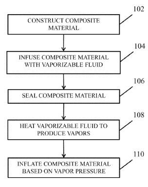
[0009] FIG. 1 is an example of a process that provides an actuating material in accordance with some embodiments of the disclosed subject matter.
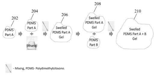
[0010] FIG. 2 is an example of manufacturing an actuating material in accordance with some embodiments of the disclosed subject matter.
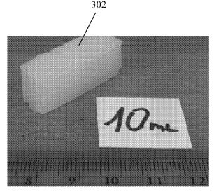
[0011] FIG. 3 is an example of an actuating material in accordance with some embodiments of the disclosed subject matter.
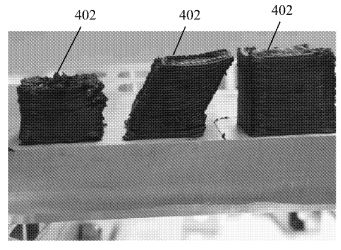
[0012] FIG. 4 is an example of a heating component for an actuating material in accordance with some embodiments of the disclosed subject matter.
[0013] FIG. 5 is an example of an actuating material including a heating component in accordance with some embodiments of the disclosed subject matter.
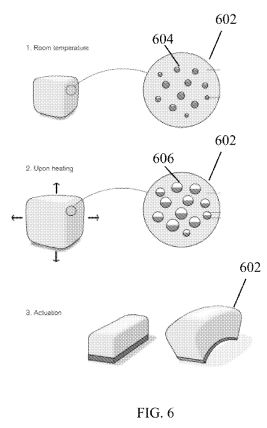
[0014] FIG. 6 is an illustration of an actuation of a vapor pressure solid actuating material in accordance with some embodiments of the disclosed subject matter.
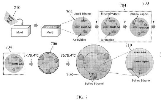
[0015] FIG. 7 is an illustration of preparing and actuating a vapor pressure solid actuating material in accordance with some embodiments of the disclosed subject matter.
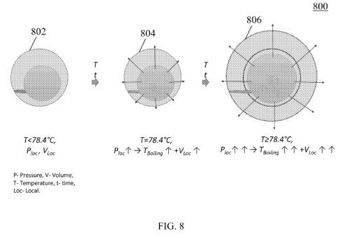
[0016] FIG. 8 is an illustration of an actuation of a vapor pressure solid actuating material in accordance with some embodiments of the disclosed subject matter.
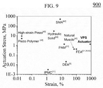
[0017] FIG. 9 is a graphical representation of a strain-stress curve for a vapor pressure solid actuating material in accordance with some embodiments of the disclosed subject matter. [0018] FIG. 10 is an example of an actuating material shown during its initial phase
(FIG. 10A) and its expanded phase (FIG. 10B) in accordance with some embodiments of the disclosed subject matter.
[0019] FIG. 11 is an example of a soft-robot using an actuating material (FIG. 11C) illustrated during its initial phase (FIGS. 11 A, 1 1D), its expanded phase (FIGS.
1 IB, 1 IE), in accordance with some embodiments of the disclosed subject matter.
[0020] FIG. 12 is an example of a soft-robot using an actuating material in accordance with some embodiments of the disclosed subject matter.
DETAILED DESCRIPTION
[0021] The disclosed subject matter relates to vapor pressure solid articles and methods for making and using the same. In some embodiments, vapor pressure solids refer to actuating (e.g., 'smart') materials that are capable of producing an output force and/or displacement as a result of a chemical reaction. For example, such materials include matrix materials that are infused with a vaporizable fluid that can expand and/or contract the matrix based on its temperature. Additionally, these types of materials do not require additional mechanical components to provide the actuation (e.g., hydraulics, motors etc.) and, as a result, they can be manufactured in bulk using smart geometric design (e.g., 3D printing) and allow for miniaturization, thus enabling uses in various bio-inspired applications.
[0022] In the following description, reference is made to the accompanying drawings that form a part hereof, and in which are shown by way of illustration specific embodiments in which the inventive principles may be practiced. It is to be understood that other embodiments may be utilized and structural changes may be made without departing from the scope of the disclosed subject matter.
[0023] FIG. 1 illustrates an exemplary method 100 for actuating a vapor pressure solid material in accordance with embodiments of the disclosed subject matter. Initially, at 102, a composite material including at least one constituent material (e.g., a matrix material) is provided. Specifically, a matrix material is selected to provide support to other materials and can include matrix components such as silicone rubber, latex, polymers (e.g., PDMS, platinum-catalyzed PDMS, tin- catalyzed PDMS), resins, or other suitable materials. In some embodiments, such a composite material can be constructed using a 3D printing technique or other suitable composition procedures. Matrix materials and vaporizable fluids can be chosen based on their chemical compatibility with each other, and other respective properties, such as the fluid's boiling point and handling restrictions, the matrix material's mechanical properties, or suitable properties.
[0024] At 104, the matrix material can be infused with a vaporizable fluid. In some embodiments an infusion can be performed using injections, infiltration of the matrix material or by using mechanical apparatuses (e.g., a Soxhlet extractor) or using suitable combinations thereof. In some embodiments, an infusion can consist of combining the vaporizable fluid with the matrix material, captivating the vaporizable fluid and/or soaking the matrix material in the vaporizable fluid. Additionally, in some embodiments the vaporizable fluid can include water, ethanol, acetone, glycerine, etheric compounds and/or other suitable fluids. Moreover, in some embodiments, a combination and/or emulsion of fluids can be automatically selected based on thermodynamic properties and desired output force from the actuating material. In some embodiments, the matrix material can be infused in an adaptive manner and at different concentrations so as to create the desired output.
[0025] At 106, the matrix material is sealed to create an insulation for the vaporizable fluid. In some embodiments, a sealing layer can be included in the matrix material using suitable materials or combinations thereof. Additionally, in some embodiments, the sealing layer can be a conductive material.
[0026] At 108, the matrix material, sealing layer and vaporizable fluid are heated so as to cause the fluid to vaporize. In some embodiments, heating can be accomplished using a heating element (e.g., one or more resistors embedded in the material) or through conductive heating by applying an adaptively controlled electrical current through the actuating material. For example, in such cases the actuating material can be modified to include one or more conductive elements and can be used alone and/or in combination with a conductive heater. Additionally, in some embodiments, a heating exchanger can be used to control the heating and/or cooling rates of the vaporizable fluid and subsequent expansion and contraction rates of the actuating material. Faster heating can be achieved using higher current or additional distributed heating networks, resulting in quicker vaporization of the vaporizable fluid. Similarly, faster cooling rates can be achieved based on the actuator's form-factor, surface-to-volume ratio, and convection currents. [0027] At 110, heating of the vaporizable fluid results in the vaporization of the fluid, and the solid is inflated based on the pressure of the vapor. Specifically, such inflation of the bulk solid can be a result of the phase transition (e.g., liquid- vapor) and/or continuous expansion of the vapors. As a result, the actuating material can be dynamically stretched and/or contracted based on the vapor pressure infused in the matrix material. Moreover, the phase transition of the vaporizable fluid into vapor combined with the one or more matrix materials can cause large expansion of the matrix, which is not typically obtained through other actuating methods. In some embodiments, the actuating material can be used in a bimorph configuration to allow for mechanical structures that are independently controlled and can produce composite output forces. For example, such composite materials can be included in piston enclosures to provide pneumatic functionality. Additionally, the actuating material can also include mechanical components (e.g., springs) in order to increase the output force and/or displacement.
[0028] FIG. 2 shows an example of mixing process 200 of the composite material with the vaporizable fluid as discussed in connection with FIG. 1 (e.g., element 104). For example, in some embodiments, a first part of PDMS gel (PDMS Part-A) composite material 202 is mixed with various amounts of ethanol (0-33vol%) 204. As a result, the mixed ethanol causes swelling of the PDMS Part-A gel as shown at 206. Subsequently, at 208, a second part of PDMS gel (PDMS Part-B) is added to the swelled gel and mixed thoroughly in order to obtain the bulk actuating material at 210. Specifically, such mixing process, allows for the introduction of air bubbles, occupied by the vaporizable fluid, in the cured actuating material providing a solid that contains isolated pores, which can be inflated upon the phase transition (e.g., liquid-vapor) and/or continuous expansion of the vaporizable fluid (e.g., ethanol). In some embodiments, the vaporizable fluid spreads in the inner walls of the bubbles while air and vapors remain in the inner part of the bubbles and causes expansion upon heating. In some embodiments, the mixed material is both castable and 3D-printable, and will solidfy in room-temperature curing. During the curing, the vaporizable fluid occupies the air bubbles, and creates new pores. The pores are expanded until equilibrium between the internal vapor pressure and external environment pressure is achieved. In some embodiments, the density of the mixed material including 20 vol.% ethanol is 0.84g/cm<3>.
FIG. 3 shows an example 300 of a vapor pressure solid actuating material in accordance with some embodiments of the disclosed subject matter. Specifically, vapor pressure solid 302 includes a PDMS elastometric matrix material as described in connection with FIG. 1 that is infused by a low-melting liquid such as ethanol. Specifically, the fluid is infused in the matrix material by mixing until the material exhibits swelling properties and the ethanol liquid is fully integrated with the PDMS matrix material. For example, in some embodiments, desired properties of the actuating material can be achieved by adding 0.5ml of liquid to each 1ml of PDMS. Upon mixing, the material is left for curing to ensure full integration of the vaporizable fluid in the matrix material. In some embodiments, curing times can be adaptively controlled to allow for different properties of the resulting actuating material. After curing, a soft solid material with entrapped fluid is obtained (e.g., 302). The actuating material is capable of significantly expanding upon heating (e.g., 100vol. %) and contracting to its initial dimensions upon cooling.
[0030] FIG. 4 shows an example 400 of a conductive heater that can be embedded in the actuating material in accordance with some embodiments of the disclosed subject matter. Specifically, conductive heater 402 can be produced using 3D printing techniques wherein the composite materials include carbon black and PDMS matrix material infused in ethanol or other suitable fluids. For example, in some embodiments, carbon black material can be added to the PDMS along with ethanol by a ratio of O. lg carbon black and 0.5ml ethanol to each 1ml of PDMS. The materials can be mixed and left to cure in order to provide the desired electrochemical properties. For example, such a conductive heater can exhibit a resistance of less than 100 Ohm, capable of conducting electrical current and allowing for rapid Joule heating while cooling down rapidly when the heating is terminated.
[0031] FIG. 5 shows an example 500 of a vapor pressure solid actuating material deposited inside the conductive heater 502 as described in connection with FIG. 4. Deposition of the vapor pressure solid can be performed in various suitable manners. In some embodiments, contact between the conductive heater and the vapor pressure solid can result in adaptively controlling the actuation of the material using selective alteration of heating and cooling cycles by means of allowing and/or interrupting the passing of the electrical current through the conductive heater. Higher current or more evenly distributed heating can produce faster expansion. Similarly, better thermal conductivity can produce faster cooling.
[0032] FIG. 6 shows an example 600 of the different phases of an actuating material
(e.g., vapor pressure solid) during heating as described in connection with FIG. 1. Specifically, matrix material 602 (e.g., silicon rubber matrix) is infused by vaporizable fluid 604 (e.g., ethanol) by for example soaking and curing while at room temperature. Subsequently, upon heating the composite material 602 using a heating element and/or a conductive heating technique, vaporizable fluid 604 commences to produce vapors 606. As a result, composite material 602 begins to expand and actuates a force and/or displacement of volume based on the pressure of the vapor.
[0033] FIG. 7 shows an example 700 of the different microscale phases of the preparation and actuation of the bulk actuating material (e.g., vapor pressure solid) as discussed above in connection with FIGS. 2 and 6. Specifically, at 702, swelled PDMS gel infused with ethanol 210 is casted and molded in order to cure and attain its final physical properties (e.g., harden, bond etc.) In some embodiments, molding and shaping can be performed automatically using 3D printing. At 704, the actuating material is at the early stages of curing whereby the infused vaporizable fluid (e.g., ethanol) has not yet reached its boiling temperature (e.g., 78.4 °C). Subsequently, as the actuating material is introduced to increasing temperatures at 704 the ethanol liquid is exposed to a rising vapor pressure, which leads to an initial volume expansion of the actuating bulk material as it approaches the fluid's phase transition boiling point (e.g., 78.4 °C) at 706. In some embodiments, such initial volume expansion can reach up to 50% of the original volume. Importantly, once the temperature reaches the fluid's phase transition point (e.g., boiling point) at 708, the vaporizable fluid (e.g., ethanol) will commence to boil leading to an immediate increase of the pressure within the bulk material. As a result, at 710, the actuating material will start to expand due to the gas expansion in order to equalize the external and internal pressure. In some embodiments, such volume expansion can reach up to 900% of the original volume at a temperature of 95 °C.
FIG. 8 shows an example 800 of the different actuation phases of the bulk actuating material (e.g., vapor pressure solid) and the relationships between the local volume, boiling temperature and local pressure. For example, at 802 while the actuating material is at rest (e.g., room temperature, pressure) no volume expansion is observed. At 804, as the material is exposed to increasing temperatures reaching the boiling point of the vaporizable fluid, the local pressure of the material increases. As a result, the volume of the material exhibits an initial expansion, while the boiling point of the fluid also increases requiring the exposure of the material to constantly increasing temperatures in order to sustain the actuation. At 806, once the temperature has exceeded the boiling point of the vaporizable fluid, the volume expansion is maximized as is the local pressure. In some embodiments, such volume maximization allows for the actuating material to lift weight that is 6000 times that of its own. [0035] FIG 9 shows a graphical representation of results obtained for the disclosed vapor pressure solid actuating material compared to other actuating materials. Graphic 900 represents a stress-strain curve of the different materials whereby stress refers to an internal force within the material associated with the deformation of the material and strain refers to the relative change in shape and size (e.g., deformation) of the material. Graphic 900 shows that the vapor pressure solid actuating material exhibits the highest strain (e.g., deformation) while experiencing moderate stress to achieve the illustrated strain. As a result, such actuating material, which does not require the use of additional equipment to induce actuation can be used for low-cost, safe and controllable miniature soft actuation systems.
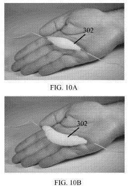
[0036] FIG. 10 shows an example of a vapor pressure solid actuating material 302 as discussed previously in reference to FIG. 3. Specifically, actuating material 302 is depicted before (see FIG. 10A) and after (see FIG. 10B) the phase transition process (e.g., liquid-gas transition) of the vaporizable fluid (e.g., ethanol) that results to the expansion of the vapor pressure solid due to increased heating. The vapor pressure solid can be electrically-actuated with a thin-resistive wire operated at low power characteristics (e.g., 8V and 1 A).
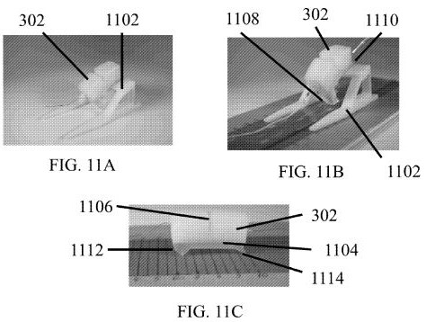
[0037] FIG. 11 shows a soft-robot using vapor pressure solid actuating material 302 (see
FIGS. 11A-11E) in accordance with some embodiments of the disclosed subject matter. In some embodiments, actuating material 302 is formed onto a layer of passive PDMS material 1104 and is used with rigid component 1102 that is able to move as a result of the expansion of the vapor pressure solid actuating material (see FIGS. 11A -11B). The passive PDMS material 1104 is formed with a first end 1108 and a second end 1110. In some embodiments, the first end 1108 is formed with solid materials, and the second end is coupled to the rigid component 1102. A notch 1106 can be formed in the actuating material 302 to facilitate bending. During actuation, the actuating material 302 expands and pushes the first end 1108 inwards along the axis of contraction. The actuation motion causes the first end 1108 to push against the floor and causes the rigid component 1102 to move in the opposite direction, along the axis of contraction.
[0038] In some embodiments, the layer of passive PDMS material 1104 includes a solid first end 1112 and a soft second end 1114 (see FIG 11C). During actuation, the actuating material 302 expands and bends due to the constricting force near the vicinity of the passive PDMS material 1104. As the actuating material 302 bends, the soft second end 1114 is pulled inward advancing it along the axis of actuation. During contraction of the material, the solid first end 1112 advances along the same axis while the soft second end 1114 remains in place, causing the soft-robot to move.
[0039] In some embodiments, the layer of passive PDMS material 1104 includes a gripper having a first finger 1116 and a second finger 1118 (see FIGS 1 1D and HE). During actuation, the actuating material 302 expands and bends causing fingers 1116 and 1118 to move inwards in a grasping motion. The actuating material 302 can remain actuated allowing the fingers 1116 and 1118 to grasp and lock onto an object. The force applied by fingers 1116 and 1118 can be adaptively controlled to enable further manipulation of the object. The fingers 1116 and 1118 can be coupled to a moveable robotic arm 1120 enabling further manipulation and movement of the object. The fingers 1116 and 1118 can be constructed of soft materials ensuring the safe manipulation of fragile items, such as for example, an egg.
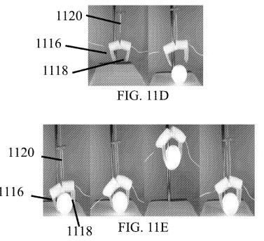
[0040] FIG. 12 shows a soft-robot using a vapor pressure solid actuating material in accordance with some embodiments of the disclosed subject matter. Specifically the actuating material is enclosed in movable member 1202 and coupled to a resistive wire conveying electrical current. The movable member 1202 operates similarly to a piston and moves triangular base 1204 of a pyramidal structure upon heating and subsequent expansion of the enclosed actuating material. For example, when the actuating material is actuated, the movable member 1202 moves an upper part of bar 1206 in a forward direction. Upon contraction of the actuating material, the bar 1206 exerts a force against the floor moving the pyramidal structure in the forward direction. The actuating material can move the pyramidal structure by applying current (8V and 1A) through the resistive wire. In some embodiments, the actuating material can be embedded in a Teflon sleeve.
[0041] The embodiments described in this disclosure can be combined in various ways.
Any aspect or feature that is described for one embodiment can be incorporated into any other embodiment mentioned in this disclosure. Accordingly, while various novel features of the inventive principles have been shown, described and pointed out as applied to particular embodiments thereof, it should be understood that various omissions and substitutions and changes in the form and details of the systems and methods described and illustrated, may be made by those skilled in the art without departing from the spirit of the invention. Amongst other things, the steps of any described methods may be carried out in different orders in many cases where such may be appropriate. Those skilled in the art will recognize, based on the above disclosure and an understanding therefrom of the teachings of the inventive principles, that different configurations and devices can be used to implement the general functionality and different embodiments of the inventive principles. Any particular method components are for illustrative purposes to facilitate a full and complete understanding and appreciation of the various aspects and functionality of particular embodiments of the present principles. Those skilled in the art will appreciate that the inventive principles can be practiced in other than the described embodiments, which are presented for purposes of illustration and not limitation.
US2017042034
SYSTEM AND METHODS FOR ADDITIVE MANUFACTURING OF ELECTROMECHANICAL ASSEMBLIES
SYSTEM AND METHODS FOR ADDITIVE MANUFACTURING OF ELECTROMECHANICAL ASSEMBLIES
A hybrid additive manufacturing approach that incorporates three-dimensional (3D) printing and placement of modules selected from a library of modules to fabricate an electromechanical assembly. By virtue of fabrication of the electromechanical assembly, mechanical properties and electrical properties of the assembly are created.
FIELD OF THE INVENTION
[0003] The invention relates generally to additive manufacturing. More specifically, the invention is directed to a hybrid approach that incorporates three-dimensional (3D) printing and placement of modules selected from a library of modules to fabricate an electromechanical assembly. By virtue of fabrication of the electromechanical assembly, mechanical properties and electrical properties of the assembly are created.
BACKGROUND OF THE INVENTION
[0004] Additive manufacturing is increasingly becoming a significant fabrication technique, both in research and industrial settings, applicable to a broad range of applications. Some commercially important additive manufacturing examples include, for example, low-cost rapid tooling manufacturing, low-volume prototype and production runs, medium-volume automotive and aerospace applications, dental restoration, orthopedic implants, custom orthotics, and user-specific artificial limbs. Furthermore, additive manufacturing methods have been used in biomedical research settings to create heterogeneous tissues from individual precursor cell types and to create functional replacements for missing or damaged body parts.
[0005] Despite a great deal of effort and the diversity of additive manufacturing techniques, no additive manufacturing process can fabricate high quality electrical interconnections, computational circuits, sensors or actuators in combination with mechanical elements in an integrated component, i.e., electromechanical component.
[0006] With Direct-Write electronics (“DW”), or the similar Direct Print (“DP”) technique, it has been demonstrated that inkjet printers are capable of fabricating transistors, and have used a combination of inkjet or digital printing and Fused Deposition Modeling (“FDM”) or Stereolithography (“SLA”) to create electrical circuits within a 3D printed part. One interesting alternative approach uses conventional semiconductor fabrication to create very small semiconductor devices that are subsequently blended with an ink binder. Although electromagnetic actuators fabricated in one process via FDM and DP has been recently demonstrated, it is rudimentary at best.
[0007] Despite this progress, enormous challenges must be overcome. Synthesizing electrically conductive materials with volume resistivity similar to bulk metals that can be extruded or deposited in a low-temperature environment (so that is it process-compatible with other materials in the assembly) remains an elusive challenge. The current state of the art, available from various vendors, employs powdered metal inks that are solvent-borne and achieve volume resistivity that is four times (4×) to ten times (10×) larger than bulk metal in the case of silver, and 10× to 50× for copper. These materials require a post-process sintering step, typically by heating to between 80 and 150 degrees Celsius (° C.) in order to achieve the stated resistivity, which can be difficult to integrate with other heat-sensitive components within the assembly. The active devices such as transistors that have been fabricated thus far have lower carrier mobility and lower on-off ratios than similar devices fabricated in silicon.
[0008] Printed transistors using complementary logic (p-channel and n-channel devices) have been combined to produce ring-oscillators, inverters and NAND (“Not AND”) gates; however low fabrication-temperature organic transistors rely on semiconductor materials that offer dramatically lower charge carrier mobilities than are available via conventional semiconductor fabrication techniques. The large discrepancy between the highest reported electron and hole mobilities for printed polymers for organic transistors imposes additional design trade-offs when fabricating complementary transistor circuits, a key component of logic circuits.
[0009] In certain situations carrier mobility impacts the drain current and the transconductance in a field effect transistor. Larger drain currents are desirable for some applications; however, as a consequence of lower mobility and larger oxide thickness, printed organic transistors typically offer drain currents that are several orders of magnitude smaller than conventional devices. It has been found that wider channels can be used to increase drain current, though this is usually accompanied by increased leakage. Resolution limitations of current printable electronics techniques impose a feature-size penalty of nearly three orders of magnitude, relative to conventional semiconductor fabrication techniques, which limits the amount by which the channel length can be reduced.
[0010] Larger transistor feature sizes lead to increased parasitic capacitances at each transistor, reducing their switching speed. Lower transconductance also limits switching speed; the propagation delay of recent fast organic transistors is at least three orders of magnitude slower than conventional transistors, limiting their use to relatively simple logic circuits since this delay accumulates with each cascaded logic cell. Printed organic semiconductors sacrifice endurance relative to conventionally fabricated circuits, with published shelf- and operating lifetimes ranging from several weeks to two years.
[0011] Conductor quality in printed electronics is impaired by incompatible material processing requirements. Low-resistivity base materials and narrow traces with high current-carrying capacity are desired In order to achieve favorable conductivity, electrically conductive materials are used. Electrically conductive materials including conductive materials that can be inkjet-printed or extruded are referred to as “inks”. These inks typically require a post-print curing or sintering step that entails heat-treating at temperatures ranging from 125 to 500° C. for an extended period of time. Since this range exceeds the glass-transition temperature of most common polymers used in additive manufacturing, the sintering step can cause other materials in the part to melt or degrade.
[0012] To circumvent this problem, alternative sintering techniques have been developed based on chemical reactions, resistive heating, plasma, photonic energy, and radio-frequency heating. Recent results compatible with low-temperature polymer substrates demonstrate conductor resistivity of 2-10× bulk via pulsed Xenon lamps, and pulsed-laser, though integration of these methods with structural additive manufacturing materials has not been demonstrated. Reactive silver inks have been shown to yield traces with conductivity nearly equal to bulk silver after 15 minutes of sintering at 90° C., though material costs may limit this approach.
[0013] A commercially available method for creating electrical conductors on the surface of plastic parts, known as Laser Direct Structuring (“LDS”), uses a laser to ablate the thermoplastic substrate where conductive traces are desired; organic-metallic additives in the plastic are activated during this process, leaving behind a surface that can be plated during successive wet metallization steps. However, like the other methods mentioned above, LDS creates electrical traces only on the surface of a part and limitations in achievable trace thickness impose constraints on current-carrying capacity despite continuing improvements in material resistivity.
[0014] An alternative fabrication approach, Shape Deposition Manufacturing (“SDM”), circumvents material and process compatibility issues by embedding prefabricated components into an assembly as it is being fabricated. This concept has been demonstrated by embedding complete assembled circuit boards as well as discrete components; these components are interconnected with embedded wires or printed conductors subject to the limitations discussed above. At a smaller scale, individual pieces of prefabricated semiconducting material referred to as “chiplets”, have been self-assembled to form functional arrays of devices over large scales, including roll-roll manufactured LED sheets, and flexible arrays of chip-scale solar cells. When fabricated with high-speed electrical interconnects on their edges, individual chiplets can be interconnected to form larger composite circuit “Quilts”. A related approach also decomposes the problem into separate high-temperature fabrication steps using conventional micro-fabrication tools, followed by a low-temperature assembly process based on transfer printing.
[0015] Existing manufacturing methods exist that embed components; however these methods rely on special-purpose embedding of particular components for specific designs. For example, U.S. Pat. No. 5,278,442 to Prinz et al. discloses electronic components formed in place by incremental material build-up of thin layers. At least one mask is used per layer to form electronic components made of conductors such as gold and copper, insulators such as ceramic materials and possibly semiconductors, all of which are applied by thermal deposition spray using a thermal deposition spray.
[0016] Another example of an existing manufacturing method that embeds components is described in U.S. Pat. No. 5,301,415 to Prinz et al., which forms three-dimensional objects by applying segments of complementary material and deposition material so as to form layers of material. Selected segments of material are then shaped after one or more segment is formed. In this manner, layers of material form a block containing the object made of deposition material and surrounded by complementary material, which may subsequently be removed.
[0017] As further described in U.S. Pat. No. 5,286,573 to Prinz et al., the support structure has a melting point lower than the melting point of the deposition material so that the support structure can be removed by a melting process.
[0018] With all of the above described methods, embedded components are printed or shaped within a complementary material, which may ultimately be removed. These components are specific to the desired application of the assembly. Though multiple additive material deposition techniques have been developed to address diverse users, existing techniques fail to address three critical requirements that electromechanical printers must satisfy. First, existing methods produce components with electrical performance that is inferior to conventionally produced electrical components by several orders of magnitude. Second, existing methods are incapable of combining the diverse materials required for complex, integrated electromechanical systems. Thus, there is a need for general-purpose, scalable manufacturing methods that employ a library of pre-fabricated modular components that are universal in manufacturing a variety of assemblies. Third, existing techniques that embed components do not contemplate or demonstrate a modular, general-purpose system. Instead they embed specific pre-fabricated components that are unique to each intended end-use or printed/assembled design. This limitation makes existing methods incapable of addressing the need for a general-purpose electromechanical 3D printer. The invention satisfies these needs.
SUMMARY OF THE INVENTION
[0019] The invention overcomes the material and process limitations of current printable electronics approaches, enabling complete, complex electromechanical assemblies to be fabricated.
[0020] The few available tools that integrate electrical and mechanical design into an electromechanical design environment do so by relying on the printed circuit board as a natural interface between the electrical and mechanical functions of the assembly. In making this choice, the traditional separations between electrical and mechanical design are entrenched: the circuit board has no mechanical functionality apart from the space that it occupies, and the mechanical components merely provide a physical substrate for the electronics. High-performance 3D-printable electrical components cannot be fabricated by existing additive manufacturing tools.
[0021] The invention is directed to finished parts with complex electromechanical properties that can be simulated, designed and fabricated. Specifically, the invention relates to an additive manufacturing process that fabricates high quality electrical interconnections, computational circuits, sensors or actuators in combination with mechanical elements in an integrated electromechanical assembly.
[0022] The invention is directed to a hybrid approach that incorporates three-dimensional (3D) printing and placement of modules selected from a library of modules to fabricate an electromechanical assembly with mechanical and electrical functionality comparable to conventionally produced planar printed circuit boards. 3D printing processes includes a variety of methods including, for example, Inkjet, Fused Deposition Modeling (“FDM”), Stereolithography (“SLA”), Drop-On-Demand/Inkjet, or Powder-bed/Binder-jetting, to name a few. Additive processes are used in 3D printing in which successive regions of material are laid down under computer control creating an object of any shape or geometry, and may be produced from a 3D model or other electronic data source. A component placement system is used to position one or module components within the object during printing.
[0023] According to one embodiment of the invention, module components used in fabrication include both electrical properties—also referred to as “electrical functionality”—and mechanical properties—also referred to as “mechanical functionality”—with each module component treated as an inherently electromechanical object. This becomes increasingly true as the module size decreases and the percent volume occupied by modules within the assembly increases. Modules with unique physical properties expand the variety available to designers.
[0024] The invention goes beyond previous system and methods that employ either a single module type, or are not modular at all, requiring components specific to the desired assembly design to be loaded into a printer. In contrast, the invention relies on a modular design philosophy: a small set of modules with generic electrical and/or mechanical functionality can be combined, in large numbers if required, to yield the desired performance.
[0025] Specifically, the invention incorporates different module types—such as a microcontroller module, resistor module, capacitor module, diode module, transistor module—that may be mechanically similar, but have distinct electrical functionality, into a 3D-printed assembly as it is being fabricated. Each module may include electrical functionality, mechanical functionality, or both. In one embodiment, the invention employs continuous material deposition via inkjet to create the portions of the assembly that require mechanical functionality, and pick-and-place manipulators to deposit modules wherever electromechanical functionality is required.
[0026] The system and methods of the invention may be used to fabricate any type of assembly, for example one that is activated when a button is depressed on the surface of the assembly. The system and methods of the invention may also be used to fabricate assemblies that exploit the programmability provided by a particular module.
[0027] Design tools such as 3D Computer Aided Design (“CAD”) systems are used to create an assembly. The assembly is created to incorporate modules by using volumes of space, or voids. A printer creates regions from conventional inkjet material and modules are positioned within the voids of the region portion created by the printer. If necessary, heating is applied to fuse modules on adjacent regions together or to fuse modules to the regions themselves. This process continues until the assembly is complete.
[0028] According to the invention, the number of unique combinations of module components positioned within a material is endless. The combination and position of module components determine the mechanical and electrical properties of the electromechanical assembly.
[0029] In a specific embodiment, the invention incorporates a limited repertoire of prefabricated modules with inkjet-deposited photopolymers to create assemblies that incorporate complex mixed-signal circuits with state of the art performance. This modular technique is scalable, allowing a single machine to produce finished parts with diverse functionality without being reconfigured and immediately commercialized using available technology.
[0030] One advantage of the invention, in contrast to related work that embeds special-purpose circuit boards within a printed assembly, the invention utilizes a small library of general-purpose modules with atomic functionality. By controlling the position and orientation of these parts within an assembly, new electrical circuits can be fabricated without re-designing individual circuit boards.
[0031] Electrical components are commercially available in thousands of distinct physical packages. This heterogeneity, while offering design flexibility, presents a challenge to methods that directly embed commercially-available electronic packages, as it requires package-specific descriptor libraries for each device envelope and footprint to be developed.
[0032] Another advantage of the invention is that it reduces designer workload by intentionally restricting the availability of components to a predetermined set that have been fully specified, facilitating circuit modeling via existing tools and eliminating the need to develop new electrical package descriptions.
[0033] Component heterogeneity also presents challenges for pick-place apparatus. Though conventional automated placement tools are flexible enough to accommodate a variety of component packages, these tools must be manually configured before each production run, with operators loading in the particular collection of components that will be used for the design. This overhead currently limits low-volume printed circuit board assembly; most commercial assembly providers employ manual assembly at very low production volumes to circumvent the setup cost. Since single-unit or ultra-low-volume production runs are a key motivation for using additive manufacturing, setup costs must be minimized, which argues for restricting the allowable components to a small set that can be permanently maintained within the printer.
[0034] In one embodiment of the invention, the allowable module components are restricted to a small set that can be permanently maintained within the printer through a library of modules. The library houses prefabricated modules with the same configuration in terms of size and shape, but differ with respect to electrical functionality and/or mechanical functionality. The modules in the library can support a variety of electrical functionality, such as currents to at least 1 Amp (A), several orders of magnitude larger than known comparable printed-electronics methods, and leverage decades of progress in semiconductor fabrication. Complementary metal-oxide-semiconductor (CMOS) processing steps for integrated circuits may be used to allow digital logic to be embedded within each module.
[0035] Methods that interconnect embedded commercial components with printed conductors are limited by conductivity (limited by conductor geometry and material volume resistivity), and process temperature, while those that employ printed semiconductors sacrifice drain current, on/off ratio, and switching speed. In contrast, electrical connectivity according to the invention is achieved through direct connections between adjacent modules, yielding composite conductors that are nearly identical to conventional copper traces.
[0036] The invention and its attributes and advantages will be further understood and appreciated with reference to the accompanying drawings.
BRIEF DESCRIPTION OF THE DRAWINGS
[0037] The preferred embodiments of the invention will be described in conjunction with the appended drawings provided to illustrate and not to the limit the invention, where like designations denote like elements, and in which:
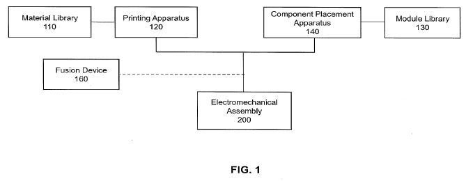
[0038] FIG. 1 illustrates a block diagram of an exemplary system for fabricating an electromechanical assembly according to the invention.
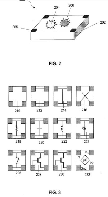
[0039] FIG. 2 illustrates a perspective view of a module component according to the invention.
[0040] FIG. 3 illustrates schematic diagrams of select module components according to the invention.
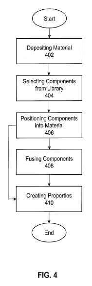
[0041] FIG. 4 illustrates a flow chart of an exemplary method for fabricating an electromechanical assembly according to the invention.
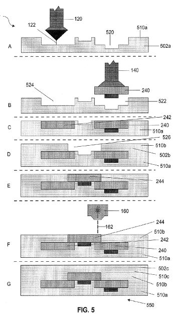
[0042] FIG. 5 illustrates a graphic representation for fabricating an electromechanical assembly according to the invention.
DETAILED DESCRIPTION
[0043] The invention demonstrates a capability that is impossible with contemporary electronics printing methods, and would require a costly electrical and mechanical design cycle, along with special-purpose tooling if it were produced following conventional electromechanical fabrication practice.
[0044] The invention is directed to a hybrid approach that incorporates three-dimensional (3D) printing and placement of modules selected from a library of modules to fabricate an electromechanical assembly with both mechanical functionality and electrical functionality comparable to conventionally produced planar printed circuit boards.
[0045] FIG. 1 illustrates a block diagram of an exemplary system 100 for fabricating an electromechanical assembly according to the invention. The system 100 facilitates a hybrid approach that incorporates devices such as a printing apparatus 120 and a component placement apparatus 140 to fabricate an electromechanical assembly 200. The printing apparatus 120 may include any type of printing functionality such as a 3D printing machine. The component placement apparatus 140 may include any type of selection and placement of components such as a high speed pick-and-place machine including with parallel pick-and-place techniques, or other similar techniques. Parallel fabrication methods may be used to exploit the mechanical regularity of the modules to manipulate entire regions simultaneously.
[0046] The printing apparatus 120 may access a material library 110 to obtain the material for printing. The material library 110 may include one or more different types of materials that may be printed, for example, photopolymers or thermoplastics, although any type of material may be used that is capable of being deposited by a 3D printing machine, including for example an inkjet process. The component placement apparatus 140 may access a module library 130 for selection of module components for positioning within the material printed by the printing apparatus 120. The module library may include different generic, prefabricated module components that vary in electrical functionality and/or mechanical functionality. Representative module components are more fully described in reference to FIG. 2 and FIG. 3 below.
[0047] In certain embodiments, a fusion device 160 such as a laser sintering machine may fuse the module components to one another in order to form an electrical connection in order to realize electrical properties. It is also contemplated the fusion device 160 may be used to fuse the module components to the material printed by the printing apparatus 120.
[0048] In addition to the module components including mechanical properties and/or electrical properties, the combination of material printed from the printing apparatus 120 and module components selected and placed by the component placement apparatus 140 create the electromechanical assembly 200 with both mechanical properties and electrical properties. Mechanical properties include, for example, stiffness, strength, stress, and strain. Electrical properties include any control of electrical energy such as circuits including, for example, resistivity and conductivity.
[0049] FIG. 2 illustrates a perspective view of a module component 200 according to the invention. Each module component 200 comprises a tile element 202 comprising a plurality of surfaces. As illustrated, the tile element 202 is generally square in shape, but any shape is contemplated. For example, the tile element may be circular, spherical, or rectangular parallelepiped, to name a few examples. In one specific embodiment, the tile element 202 is a 3 millimeter (mm) square shape with a thickness of 0.9 millimeters (mm) in order to allow easy scaling to higher levels of additive manufacturing. However, the invention is applicable to module components of any size that are amenable to manipulation using a component placement apparatus.
[0050] The tile element 202 includes one or more pads 205 that may be used for connections. The pads 205 are shown on a top surface of the module component 202, but pads may also be located on the surface opposing the top surface. As an example, pad on the top surface may be connected to pads on the bottom surface by a via in each pad. It is also contemplated that the pads may provide programming signals, enabling the printing apparatus 120 (FIG. 1) to individually program each module.
[0051] An electrical element 204 and/or a mechanical element 206 may be either positioned on a surface of the tile element 202 or within a surface of the tile element 202 in order to create functionality/properties—electrical/mechanical—for the prefabricated module component 200 for entry into the module library 130 (FIG. 1). The surface opposing the surface that includes the electrical element 204 and/or a mechanical element 206 is generally planar. Electrical elements 204 control electrical energy and may include, for example, 2-way connect, 4-way connect, crossover connect, resistor, capacitor, inductor, diode, transistor, switch, and microcontroller, as seen schematically in FIG. 3. Mechanical elements 206 control mechanical energy and may include any working or moveable function, such as a gripper or robot effector.
[0052] FIG. 3 illustrates schematic diagrams of select module components 204 according to the invention. As shown more specifically in FIG. 3, a blank module component 210 does not include an electrical element or mechanical element. Module component 212 illustrates a 2-way connect. Module component 214 illustrates a 4-way connect. Module component 216 illustrates a crossover connect. Module component 218 illustrates a resistor. Module component 220 illustrates a capacitor. Module component 222 illustrates an inductor. Module component 224 illustrates a diode, specifically a Light Emitting Diode (“LED”). Module component 226 illustrates a switch. Module component 228 and module component 230 illustrate transistors, specifically a p-channel field-effect transistor (“P-FET”) and a n-channel field-effect transistor (“N-FET”), respectively. Module component 227 illustrates a microcontroller.
[0053] The system and methods according to the invention were used to fabricate a 2.5-D interconnection in which neighboring modules on the same region rely on offset modules above or below for electrical connections. Electrical circuits are formed by creating chains of modules on 2 or more regions. This approach allows new modules to be added to an assembly at any vacant location, avoiding interference fits that would otherwise require high-precision placement or large mating forces. This 2.5-D interconnection strategy is one of several contemplated topologies; other strategies compatible with this invention include full 3D interconnections (in-plane connections between modules).
[0054] It is contemplated that all modules may share the same mechanical interface, for example 3 mm square, 0.9 mm thick, with four square pads on the top and bottom. These dimensions are incidental, as they are driven by the printed circuit board fabrication methods employed to produce the modules. The invention is equally applicable to smaller modules produced via micro-fabrication, with the added capability of embedding the electronic functionality within, rather than on top of, each module.
[0055] With the exception of the blank module 210 of FIG. 3), the topside pads of each module are connected to their corresponding bottom side pads by a via in each pad. Eight of the module types implement carrier boards for commercially available electronic components, breaking out disparate package connections into a common format. While some modules support electrical elements 204 (FIG. 2) positioned on or within their top side, certain modules may not have components on or within their bottom side in order to facilitate automated manipulation. In alternate embodiments, the electrical elements 204 and/or mechanical elements 206 may be positioned on or within one or more surfaces of the module component 200.
[0056] In particular embodiments, the FET modules 228, 230 support drain currents in excess of 3 A and can be used with signals as fast as 10 Megahertz (MHz). The microcontroller module 232 employs an Atmel ATtiny10 that contains 1 kB of code space, 32 bytes of RAM, an analog to digital converter, internal oscillators, and timer circuitry. This module's pads may also provide programming signals, enabling the printer to individually program each microcontroller module as it is placed.
[0057] FIG. 4 and FIG. 5 illustrate exemplary methods for fabricating an electromechanical assembly according to the invention. Specifically, FIG. 4 is a flow chart and FIG. 5 is a graphic representation.
[0058] As shown in FIG. 4 at step 402, material is selected and deposited into a plurality of stacked regions, each successive region positioned on top of the previous region. At step 404, module components are are selected from a library of modules. The module components are positioned into the material at step 406. In certain embodiments, the module components may be fused together or fused to the material as shown in step 408. At step 410, mechanical properties and electrical properties are created by virtue of fabrication of the electromechanical assembly.
[0059] FIG. 5 illustrates a graphic representation for fabricating an electromechanical assembly. As shown in FIG. 5, step “A” is directed to a first device 120 depositing material 122, for example using an inkjet process, into a plurality of stacked regions 502a with each successive region positioned on top of the previous region. The plurality of stacked regions 502a forms a base region portion 510a including one or more void elements 520 as constructed by the material 122 such as a photopolymer material.
[0060] As shown by step “B”, a second device 140 such as a high speed pick-and-place machine, selects a module component 240 from the library of module components and positions the module component 240 in one of void elements 522, 524.
[0061] Step “C” illustrates both module components 240, 242 positioned within the base region portion 510a. Step “D” illustrates a second plurality of stacked regions 502b forming a top region portion 510b deposited by the inkjet 3D printing machine 120. The top region portion 510b encapsulates all or a portion of the module components 240, 242 while forming void element 526.
[0062] As shown by step “E”, the high speed pick-and-place machine 140 selects module component 244 and positions it in void element 526.
[0063] In certain embodiments, a fusion device 160 as shown in step “F”, such as a laser sintering machine, applies heat in the form of a laser beam 162 in order to fuse the module components 240, 242, 244 to one another. The laser sintering machine 160 may also apply heat to fuse the module components 240, 242, 244 to a region portion 510a, 510b.
[0064] As shown in step “G”, material is deposited into a third plurality of stacked regions 502c with each successive region positioned on top of the previous region. The plurality of stacked regions 502c forms a second top region portion 502c that encapsulates all of the module components 240, 242, 244 forming an electromechanical assembly 550. By virtue of fabrication of the electromechanical assembly 550, mechanical properties and electrical properties of the assembly are created.
[0065] The system and methods of the invention may be used to fabricate any type of assembly, for example an LED keychain light, activated when a button is depressed on the surface. The system and methods of the invention may be used to fabricate assemblies that exploit the programmability provided by a microcontroller module.
[0066] For example, a microcontroller module may be programmed to create specific pulse-trains such as those that correspond to the on and on-off pulses in a particular infra-red (IR) remote control protocol. These pulses can be used to turn an IR LED on and off, controlling a remote device. Another example includes the play/pause, jog forward, jog backward, volume up and volume down functions, creating a 5-channel IR remote control. Each of the assemblies employ the inkjet-printed material as a supportive structure, and the remote utilizes a flexible material around the buttons that allows motion during button-press events.
[0067] Another example of an assembly incorporates a LED into a structure that has full electromechanical functionality. Inkjet-produced areas can incorporate components such as rack-and-pinion connections, captive hinges, and springs. When one component is activated, one or more other components may be activated. For example, when a component on a gripper is activated, the gripper arms open and an internal switch closes, activating an illumination component.
[0068] While the disclosure is susceptible to various modifications and alternative forms, specific exemplary embodiments of the invention have been shown by way of example in the drawings and have been described in detail. It should be understood, however, that there is no intent to limit the disclosure to the particular embodiments disclosed, but on the contrary, the intention is to cover all modifications, equivalents, and alternatives falling within the scope of the disclosure as defined by the appended claims.
US9487387
SYSTEM AND METHODS FOR ACTUATION USING ELECTRO-OSMOSIS
SYSTEM AND METHODS FOR ACTUATION USING ELECTRO-OSMOSIS
FIELD OF THE INVENTION
The invention relates generally to micro-fluidics and more specifically to a system and methods for creating very low energy micro-scale and macro-scale mechanical actuators through use of one or more electro-osmotic pumps.
BACKGROUND OF THE INVENTION
Most conventional mechanical pumps have issues with reliability due, in part, to the moving components. However, pumps that do not require moving components such as electro-osmotic pumps (EOPs) make them suitable for a variety of applications, including for example “lab-on-a-chip” devices, diagnostic devices, micro total analysis systems (μMTAS), drug delivery systems, and separation and mixing processes, as well as micro-processor cooling systems, to name a few.
Electro-osmosis is used to pump fluids that contain some quantity of charged species, such as positive and negative ions. An electric double layer is a structure that appears on the surface of an object when it is exposed to a fluid. The object might be a solid particle, a gas bubble, a liquid droplet, or a porous body. The electric double layer refers to two parallel layers of charge surrounding the object. The first layer comprises ions adsorbed onto the object due to chemical interactions. The second layer is composed of ions attracted to the surface charge. This second layer is loosely associated with the object. It is made of free ions that move in the fluid under the influence of electric attraction.
Most solid surfaces acquire a surface electric charge when brought into contact with a liquid. When an electric field is applied across the liquid, the ions in the double-layer migrate in the field, which results in viscous drag to create bulk fluid flow and generation of a net pressure. This effect is referred to as electro-osmosic pumping, or EOP pumping. Specifically, EOPs provide fluid flow due to movement of an electric double layer that forms at the solid-liquid interface. Not only do EOPs eliminate moving components, but EOPs also move fluid using the electric field. EOPs can move low conductivity fluids and have a greater pressure and flow rate change when compared to conventional pumps.
Thus, there is a need for low energy mechanical actuators that are of a simple design and construction. The invention satisfies this need.
SUMMARY OF THE INVENTION
The invention exploits a widely used device in micro-fluidics, the electro-osmotic pump (EOP), to create very low energy micro-scale and macro-scale mechanical actuators. The EOP uses electrical fields to move naturally occurring charged particles (ions) through a fluid medium. As the ions move in response to the applied field, they drag the (non-charged) fluid along, establishing bulk flow. When confined to a narrow chamber, a pressure gradient can be established. The combination of pressure gradient and bulk flow performs mechanical work, for example, fluid flow control (i.e. actuators, valves), linear actuators (e.g. for artificial muscles), micro-electro-mechanical system (MEMS) devices (e.g. micro-pistons in bulk silicon), and quasi-sealed actuators that expand and contract to realize both linear and bending motion.
The invention relies on individual micro-scale actuators that can be combined in any number including to produce a macro-scale actuator structure with better power density, increased reliability and lower production cost. With the use of electro-osmotic pumps, the invention enables actuators to be constructed in a variety of embodiments, including for example, a sheet structure, a piston structure, and a cellular structure, to name a few.
When compared to the small number of other efforts that have applied electro-osmotic pumping to actuation, the invention improves on these efforts in two key areas: (1) production of linear strain that can be scaled down for micro-actuators and scaled up for macro-actuators, and (2) mass-production using commercially available processes that is also cost-effective.
When compared to other types of hydraulic actuation, the invention yields high-force, high-strain linear and rotary actuators that are cheap to produce, and are at least an order of magnitude more efficient. These actuators are extremely valuable to the robotics community, since power generation and storage is one of the key limiting factors for the performance of mobile robots. However, these actuators are general purpose and can be applied to any area in which low cost and energy efficiency are priorities.
Certain embodiments of the invention are particularly suited to cost-sensitive areas, since they are intended to be produced with a very high-volume reel-to-reel production technique that reduces the individual component cost. Certain other embodiments are intended to be the actuation building block for a new paradigm of modular micro-machines. One goal is to provide a small set of micro-fabricated modular building blocks that form the basis for larger, more complex machines. The key different building block types include computation, power storage and transmission, structure, and actuation. Large numbers of these standardized building blocks may be prefabricated to establish the building blocks in specific locations in order to build an actuator assembly.
Certain other embodiments of the invention integrate a plurality of electro-osmotic pumps within a flexible material in order to provide an actuator with uniquely controllable states. For example, certain portions of the actuator can be curled up or curled down while maintaining a somewhat rigid state while other portions of the actuator can be soft and pliable. Therefore, actuators of this embodiment enable low or zero-power rigid portions.
Certain other embodiments may be of a more complex structure by incorporating an inherently three-dimensional (3D) mechanism so that the electro-osmotic pumps can move fluid vertically.
Specifically, the invention constructs micro-actuators that require very few moving parts, which is far more efficient than other hydraulic actuators, vastly simplifies the actuator design relative to other micro-actuators, offers large force output, and can be readily scaled to create macro-scale actuators that are composed of millions of individual actuators.
Some advantages of the invention include, for example, the creation of high efficiency actuators with a very low energy requirement, actuators of simple design with very few moving parts, actuators that can exude a large force output, and actuators that are readily scalable from micro-scale to macro-scale actuators.
The present invention and its attributes and advantages may be further understood and appreciated with reference to the detailed description below of contemplated embodiments, taken in conjunction with the accompanying drawings.
DESCRIPTION OF THE DRAWING
The accompanying drawings, which are incorporated in and constitute a part of this specification, illustrate an implementation of the invention and, together with the description, serve to explain the advantages and principles of the invention:
FIG. 1 illustrates an exploded view of one embodiment of an actuator in the form of a sheet structure according to the invention.
FIG. 2 illustrates the actuator of FIG. 1 in a relaxed state according to the invention.
FIG. 3 illustrates the actuator of FIG. 1 in a contracted state according to the invention.
FIG. 4 illustrates a cross-section of another embodiment of an actuator in the form of a piston structure according to the invention.
FIG. 5 illustrates another embodiment of an actuator in the form of a cellular structure according to the invention.
FIG. 6 illustrates the actuator of FIG. 6 with a portion actuated to bend slightly according to the invention.
FIG. 7 illustrates the actuator of FIG. 6 with a portion actuated to curl upward according to the invention.
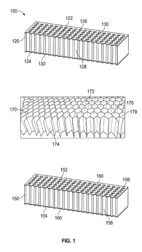
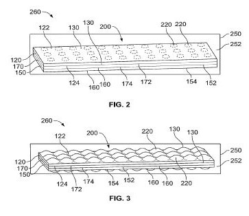
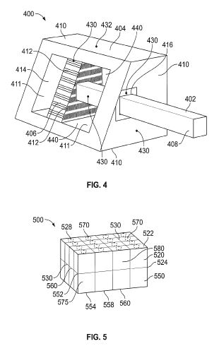
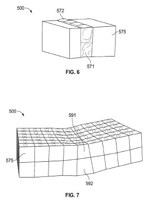
DETAILED DESCRIPTION OF THE INVENTION
All electro-osmotic pumps exploit the natural equilibrium-state distribution of ions at a fluid/solid interface. This distribution, known as the electrical double layer, results in a net charge on the solid and an equal, but opposite, net charge in the fluid near the surface of the solid. This charged fluid can be moved when an externally applied electric field is applied.
For exemplary purposes, the invention is discussed with respect to three embodiments: a sheet structure, a piston structure, and a cellular structure. However, it should be noted that the invention is not limited to these three embodiments, but that electro-osmotic pumps can be used to construct actuators in a variety of embodiments.
In one embodiment of the invention, the actuator is in the form of a sheet structure as shown in FIG. 1 through FIG. 3. FIG. 1 illustrates an exploded view of one embodiment of an actuator in the form of a sheet structure 100 according to the invention. The sheet structure 100 comprises a plurality of sheets—three sheets 120, 150, 170 as shown in FIG. 1 through FIG. 3; however, any number of sheets are contemplated. Each sheet 120, 150, 170 are constructed from a flexible, inelastic material such as a polymer.
The first flexible sheet 120 includes a first top side 122 and a first bottom side 124. The first top side 122 and the first bottom side 124 are coated with a first conductive layer 130 and the first flexible sheet 120 comprises a plurality of first chambers 128.
The second flexible sheet 150 includes a second top side 152 and a second bottom side 154. The second top side 152 and the second bottom side 154 are coated with a second conductive layer 160. Like the first flexible sheet 120, the second flexible sheet 150 comprises a plurality of second chambers 158.
A third flexible sheet 170 includes a third top side 172 and a third bottom side 174, wherein the third flexible sheet 170 comprises a plurality of third chambers 178 of a honey-comb arrangement 179.
As shown in FIG. 2, the second top side 152 of the second flexible sheet 150 is fused to the third bottom side 174 of the third flexible sheet 170 at a plurality of regular intervals and the first bottom side 124 of the first flexible sheet 120 is fused to the third top side 172 of the third flexible sheet 170 at a plurality of regular intervals to obtain an assembled flexible sheet structure 200 including a plurality of assembled chambers 220.
Each of the sheets 120, 150, 170 as shown in FIG. 1 can be mass produced as a rolled sheet. The assembled flexible sheet structure 200 is then formed using a reel to reel process that fuses the sheets 120, 150, 170 together at specific locations using heat and pressure in order to produce specific chambers 220.
The assembled flexible sheet structure 200 is positioned inside an outer membrane 250 that includes a working fluid 252 to form an actuator 260.
For purposes of this application, a working fluid is any gas or liquid that actuates the actuator. Examples of working fluids include for example, water, steam, pentane, toluene, chlorofluorocarbons, hydro-chlorofluorocarbons, fluorocarbons, propane, butane, isobutene, ammonia, sulfur dioxide, helium, etc.
As shown in FIG. 2 and FIG. 3, the assembled flexible sheet structure 200 contracts and expands to form a linear actuator when a voltage is applied to pump the working fluid 252 across the assembled flexible sheet structure 200 and into the plurality of assembled chambers 220.
More specifically, the conductive layer 130, 160 enables a charge to be externally applied. When opposite charges are applied to the assembled flexible sheet structure 200—specifically the conductive layers 130, 160—the working fluid 252 is forced through the assembled chambers 220 and swells the chambers 220 formed by the third flexible sheet 170 as shown in FIG. 3.
In one embodiment, it is contemplated that the chambers 220 range from 200 nanometers to several micrometers, depending on the design goals and the working fluid 252. In addition, it is contemplated that the chambers 220 may be approximately one millimeter in each planar dimension with the entire assembled flexible sheet structure 200 being several hundred micrometers thick. Again, these dimensions are not fixed and can be easily changed depending on the specific goals. In general however, a typical sheet structure actuator can employ hundreds of thousands to millions of individual chambers in a single sheet. For example, using the approximate chamber dimensions previously provided, a sheet structure actuator 10 centimeters long that employs a rolled sheet of chambers that is 10 centimeters long before being rolled would contain over 100,000 individual chambers.
FIG. 2 illustrates the actuator 260 in a relaxed state whereas FIG. 3 illustrates the actuator 260 in a contracted state according to the invention. As shown in FIG. 3, the swelling of chambers 220 stretches the flexible, inelastic sheets 120, 150, causing a contraction. This motion can be exploited to create low cost, batch-fabricated linear actuators such as artificial muscles.
In another embodiment of the invention, the actuator is in the form of a piston structure as shown in FIG. 4. In the piston structure embodiment, the electro-osmotic pumps perform two distinct functions: (1) pumping and (2) sealing. The pumping function moves fluid from one side of the piston to the other, forcing the piston to move. The sealing function prevents fluid from slipping past the piston (between the piston and the chamber wall) without also forcing the piston to move.
The piston structure according to the invention employs widely used micro-fabrication techniques to create micro-pistons in bulk silicon. This design yields high actuator force with low actuation power, and exploits the electro-osmotic pump to avoid complex seals at the pump/fluid boundaries.
In this piston structure embodiment, the invention is intended to be implemented in traditional microelectromechanical systems (MEMS) setting using bulk silicon and various etch and plate stages.
The piston structure actuator 400 comprises a piston 402 positioned within an enclosed chamber 404. Specifically, the piston 402 includes a head 406 and a cylinder 408. The enclosed chamber 404 includes a plurality of outside surfaces 410 and a plurality of inside surfaces 411. The head 406 of the piston 402 includes a plurality of perforations 412.
The enclosed chamber 404 is filled with a working fluid 414, wherein the enclosed chamber 404 includes an aperture 416 through which the piston 402 is positioned within the enclosed chamber 404.
The piston structure actuator 400 includes one or more electrodes 430. In one embodiment, the one or more electrodes 430 are positioned on either side of one or more perforations 412 of the head 406. In another embodiment, the one or more electrodes 430 are positioned at two opposing outside surfaces 410 of the enclosed chamber 404. In another embodiment, the one or more electrodes 430 are positioned at the aperture 416 of the enclosed chamber 404. It is further contemplated that one or more conductors 432 can be used to connect the one or more electrodes 430 to an outside surface 410 of the enclosed chamber 404.
In the embodiment with one or more electrodes 430 positioned at two opposing outside surfaces 410 of the enclosed chamber 404, a weaker electric field for the same applied voltage is realized, but this embodiment avoids the need for conductors 432 that connect the electrodes 430 on the piston 402 to the outside surface 410 of the chamber 404.
The one or more electrodes 430 are configured to be charged to create an electric field in order to move the working fluid 414 and actuate the piston 402. Specifically, when the one or more electrodes 430 are charged, the resulting electric field causes the working fluid 414 to flow from one insides surface 411 to another inside surface 411 of the enclosed chamber 404 causing the piston 402 to move.
More specifically, the pumping and sealing functions are both accomplished by the same electro-osmotic pump that uses the one or more electrodes 430 on the piston 402 itself, and is formed by the gap 440 between the cylinder 408 and an inside surface 411 of the chamber 404. When the electrodes 430 are energized, the working fluid 414 is forced to flow within the gap 440, causing a bulk flow of the working fluid 414 from one side of the piston 402 to the other. This approach avoids flexible seals which are difficult to fabricate and cause friction losses or stiction—the static friction that needs to be overcome to enable relative motion of stationary objects in contact.
It is also contemplated that a second electro-osmotic pump may be implemented, separate and apart from the piston structure actuator 400, that moves working fluid from one side of the piston to the other via microfluidic channels that lead to either side of the piston (these channels might lead to either end of the chamber, for example). This version is more complicated, but allows greater fluid pressures and flow rates.
FIG. 5 through FIG. 7 illustrate another embodiment of an actuator in the form of a cellular structure 500 according to the invention. In this embodiment, the invention uses an array of identical chambers that are separated by individually addressable permeable layers. Rather than pumping the working fluid from outside the assembly as described in the embodiment of FIG. 1 through FIG. 3, it uses pumps that separate different cellular chambers to move the working fluid between chambers. This motion swells some chambers while shrinking others. Some of these chambers employ inelastic inner struts which bias the contraction/expansion due to fluid motion to cause non-isotropic expansion or contraction. This approach can yield actuators that are sealed, yet realize both linear and bending motion.
Similar to the first embodiment described in FIG. 1 through FIG. 3, the cellular structure 500 comprises a plurality of sheets 520, 550 that are constructed from a flexible, inelastic material such as a polymer.
The first flexible sheet 520 includes a first top side 522 and a first bottom side 524. The first top side 522 and the first bottom side 524 are coated with a first conductive layer 530 and the first flexible sheet 520 comprises a plurality of first chambers 528.
The second flexible sheet 550 includes a second top side 552 and a second bottom side 554. The second top side 552 and the second bottom side 554 are coated with a second conductive layer 560. Like the first flexible sheet 520, the second flexible sheet 550 comprises a plurality of second chambers 558.
As shown in FIG. 5, the second top side 552 of the second flexible sheet 550 is fused to the first bottom side 524 of the first flexible sheet 520 at a plurality of regular intervals to obtain an assembled flexible cellular structure 500 including a plurality of assembled chambers 570.
A working fluid 575 is positioned inside the flexible cellular structure 500 to create the mechanical actuator, wherein the plurality of assembled chambers 570 are separated by individually addressable permeable layers 530, 560 such that voltage applied to one or more individually addressable permeable layers 530, 560 causes the working fluid 575 to flow from one assembled chamber 570 into an adjacent assembled chamber 570 such that select assembled chambers 570 of the plurality are configured to contract and expand. Furthermore, an inelastic inner strut 580 may be positioned within each assembled chamber 570 to bias the contraction and expansion of the chamber 570.
FIG. 6 illustrates the actuator of FIG. 6 with a portion actuated to bend slightly according to the invention. Working fluid 575 from four of the chambers 571 has been pumped into the four chambers 571 directly above them causing the chambers 571, 572 to swell or contract causing the entire assembled cellular structure 500 to bend.
FIG. 7 illustrates the actuator of FIG. 6 with a portion actuated to curl upward according to the invention. Working fluid 575 pumped from chamber 591 into the chamber 592, causing chamber 591 to contract and chamber 592 to swell, which causes the actuator in the form of a cellular structure 500 to curl upward. Specifically, the resulting tension draws the ends of the actuator together.
Similar to the other embodiments of the invention, the actuator in the form of a cellular structure 500 can be built on a reel-reel process. As shown two sheets are stacked; however, multiple sheets may be stacked in order to create a many-layer stack-up.
http://onlinelibrary.wiley.com/doi/10.1002/adem.201600271/abstract;jsessionid=CC6DBE084B5577BF47EB3E502CC168CB.f04t04
Electrically Actuated Hydraulic Solids
Abstract
The authors introduce a new class of electrically-actuated soft materials. Electro-active hydraulic solids (EAHSs) are comprised of numerous microscale phase change capsules embedded inside a conductive elastomer matrix which replicate traditional wax actuators in a massively parallel fashion. EAHS can generate forces and stress densities that exceed traditional electroactive actuators. For example, a 14 mm diameter 50 mm long cylinder can generate 4 500 N force and have over 3% strain. The authors describe a simple method for fabricating EAHS and demonstrate their compatibility with a wide range of manufacturing processes including additive manufacturing, subtractive manufacturing, and forming.
http://onlinelibrary.wiley.com/doi/10.1002/app.44116/full
Improvement of actuation performance of dielectric
elastomers by barium titanate and carbon black fillers
M. Poikelsipaa, et al.
ABSTRACTM. Poikelsipaa, et al.
Dielectric elastomers are promising materials for actuators resembling human muscle. Among elastomers, acrylic rubbers (ACM) have shown good actuation performance but its use is limited by the high operating voltages required. The present work demonstrates that simultaneous incorporation of nanostructured carbon black and dielectric fillers offers an increase in a dielectric permittivity and a suitable modulus of the elastomers matrix, enabling an improved electro-mechanical actuation performance at low voltages. By the use of reinforcing carbon black and barium titanate in an acrylic elastomer matrix a sixfold increase in the dielectric permittivity was realized. A fine tuning of the actuation stress and, consequently, actuation strain can be done by a judicial selection of the different filler concentrations in the soft rubber matrix. Finally, a synergistic effect of the fillers was observed in the improved actuation performance of the developed materials. This work may pave the way to design dielectric elastomers for actuator fabrication. © 2016 Wiley Periodicals, Inc. J. Appl. Polym. Sci. 2016, 133, 44116.